JP3809403B2 - Imaging device, external processing device, control program for imaging device, control program for external processing device - Google Patents
Imaging device, external processing device, control program for imaging device, control program for external processing deviceDownload PDFInfo
- Publication number
- JP3809403B2 JP3809403B2JP2002207363AJP2002207363AJP3809403B2JP 3809403 B2JP3809403 B2JP 3809403B2JP 2002207363 AJP2002207363 AJP 2002207363AJP 2002207363 AJP2002207363 AJP 2002207363AJP 3809403 B2JP3809403 B2JP 3809403B2
- Authority
- JP
- Japan
- Prior art keywords
- external processing
- imaging
- image
- processing device
- type
- Prior art date
- Legal status (The legal status is an assumption and is not a legal conclusion. Google has not performed a legal analysis and makes no representation as to the accuracy of the status listed.)
- Expired - Fee Related
Links
Images


Classifications
- G—PHYSICS
- G06—COMPUTING OR CALCULATING; COUNTING
- G06F—ELECTRIC DIGITAL DATA PROCESSING
- G06F3/00—Input arrangements for transferring data to be processed into a form capable of being handled by the computer; Output arrangements for transferring data from processing unit to output unit, e.g. interface arrangements
- G06F3/12—Digital output to print unit, e.g. line printer, chain printer
- H—ELECTRICITY
- H04—ELECTRIC COMMUNICATION TECHNIQUE
- H04N—PICTORIAL COMMUNICATION, e.g. TELEVISION
- H04N1/00—Scanning, transmission or reproduction of documents or the like, e.g. facsimile transmission; Details thereof
- H04N1/00127—Connection or combination of a still picture apparatus with another apparatus, e.g. for storage, processing or transmission of still picture signals or of information associated with a still picture
- H04N1/00278—Connection or combination of a still picture apparatus with another apparatus, e.g. for storage, processing or transmission of still picture signals or of information associated with a still picture with a printing apparatus, e.g. a laser beam printer
- H—ELECTRICITY
- H04—ELECTRIC COMMUNICATION TECHNIQUE
- H04N—PICTORIAL COMMUNICATION, e.g. TELEVISION
- H04N2201/00—Indexing scheme relating to scanning, transmission or reproduction of documents or the like, and to details thereof
- H04N2201/0008—Connection or combination of a still picture apparatus with another apparatus
- H04N2201/001—Sharing resources, e.g. processing power or memory, with a connected apparatus or enhancing the capability of the still picture apparatus
- H—ELECTRICITY
- H04—ELECTRIC COMMUNICATION TECHNIQUE
- H04N—PICTORIAL COMMUNICATION, e.g. TELEVISION
- H04N2201/00—Indexing scheme relating to scanning, transmission or reproduction of documents or the like, and to details thereof
- H04N2201/0008—Connection or combination of a still picture apparatus with another apparatus
- H04N2201/0013—Arrangements for the control of the connected apparatus by the still picture apparatus
Landscapes
- Engineering & Computer Science (AREA)
- Multimedia (AREA)
- Signal Processing (AREA)
- Theoretical Computer Science (AREA)
- Human Computer Interaction (AREA)
- Physics & Mathematics (AREA)
- General Engineering & Computer Science (AREA)
- General Physics & Mathematics (AREA)
- Television Signal Processing For Recording (AREA)
- Studio Devices (AREA)
- Accessory Devices And Overall Control Thereof (AREA)
- Facsimiles In General (AREA)
Description
Translated fromJapanese【0001】
【発明の属する技術分野】
本発明は撮像装置、外部処理装置、撮像装置のための制御プログラム及び外部処理装置のための制御プログラムに関する。
【0002】
【従来の技術】
従来、デジタルカメラ等のデジタル撮像装置で、撮影した画像を印刷処理するには、一旦パーソナルコンピュータのような計算機に画像データをダウンロードし、その画像を印刷するためのアプリケーションを用いて、計算機と接続しているプリンタに出力するという作業を行っている。
【0003】
上記技術では、利用者は計算機上のアプリケーションにより画像の一覧情報およびファイル名をディスプレイに表示された情報をもとに検索し、出力データを選択することで印刷を行っている。これに対して最近は、PCを介することなく、直接、デジタルカメラからカラープリンタにデジタル画像データを伝送して印刷することができるカラープリントシステムや、デジタルカメラに搭載され、撮像した画像を記憶しているメモリカードを、直接、カラープリンタに装着し、そのメモリカードに記憶されている、撮影された画像を印刷できる、所謂フォトダイレクト(PD)プリンタ等も開発されている。
【0004】
【発明が解決しようとする課題】
しかし、デジタルカメラから直接プリンタに画像データを伝送して印刷する場合は、デジタルカメラは各メーカごとにその仕様や操作方法などが異なっているため、各種メーカのデジタルカメラに対応できるフォトダイレクトプリンタ装置の出現が望まれている。このように、各メーカのデジタルカメラを直接接続して印刷するプリンタ装置では、各カメラで任意に設定される印刷情報と、プリンタ装置における印刷条件との整合を取る必要が生じる。
【0005】
本発明は、上記従来の問題点を解消するために成されたもので、携帯性を活かした撮影ができ、外部処理装置によって容易に撮影画像の印刷等の処理ができる撮像装置または外部処理装置の提供を目的とするものである。
【0006】
また、他の発明の目的は、撮像装置と外部処理装置を有線または無線で接続して画像信号を転送する際に、その外部処理装置を自動認識し、最適なモードで外部処理装置で印刷等の処理をできるように制御することを可能にする撮像装置または外部処理装置を提供しようとするものである。
【0007】
【課題を解決するための手段】
この問題を解決するため、例えば第1の発明の撮像装置は以下に示す構成を備える。
【0008】
すなわち、被写体の光像を電気的画像信号に変換する撮像手段と、外部処理装置との通信が可能なインターフェースと、前記画像信号を前記外部処理装置に転送して処理するための制御手段とを備えた撮像装置であって、前記制御手段は、前記インターフェースを介して前記外部処理装置と通信することによって撮像装置と外部処理装置の制御関係が、撮像装置内部のメモリを前記外部処理装置から直接アクセスする第1のタイプか、撮像装置のコントローラにより前記外部処理装置における処理を制御することが可能な第2のタイプかを判別する判別手段と、該判別結果に基づき前記撮像装置内部の画像を前記外部処理装置により処理するための処理手順を変更する処理制御手段とを有することを特徴とする。
【0009】
また、他の発明の外部処理装置は、被写体の光像を電気的画像信号に変換し外部処理装置との通信が可能なインターフェースとを備えた撮像装置と通信する外部処理装置であって、前記インターフェースを介して前記撮像装置と通信することによって、撮像装置と外部処理装置の制御関係が、撮像装置内部のメモリを前記外部処理装置から直接アクセスする第1のタイプか、撮像装置により前記外部処理装置における処理を制御することが可能な第2のタイプかを判別する判別手段と、該判別結果に基づき前記撮像装置内部の画像を前記外部処理装置により処理するための処理手順を変更する処理制御手段とを有することを特徴とする。
【0010】
また、他の発明の撮像装置のための制御プログラムは、被写体の光像を電気的画像信号に変換する撮像手段と、外部処理装置との通信が可能なインターフェースと、前記画像信号を前記外部処理装置に転送して処理するための制御手段とを備えた撮像装置のための制御プログラムであって、前記制御プログラムは前記インターフェースを介して前記外部処理装置と通信することによって撮像装置と外部処理装置の制御関係が、撮像装置内部のメモリを前記外部処理装置から直接アクセスする第1のタイプか、撮像装置のコントローラにより前記外部処理装置における処理を制御することが可能な第2のタイプかを判別する判別ステップと、該判別ステップの結果に基づき前記撮像装置内部の画像を前記外部処理装置により処理するための処理手順を変更する処理制御ステップとを有することを特徴とする。
【0011】
また、他の発明の外部処理装置のための制御プログラムは、被写体の光像を電気的画像信号に変換し外部処理装置との通信が可能なインターフェースとを備えた撮像装置と通信する外部処理装置のための制御プログラムであって、前記インターフェースを介して前記撮像装置と通信することによって、撮像装置と外部処理装置の制御関係が、撮像装置内部のメモリを前記外部処理装置から直接アクセスする第1のタイプか、撮像装置により前記外部処理装置における処理を制御することが可能な第2のタイプかを判別する判別ステップと、該判別ステップの結果に基づき前記撮像装置内部の画像を前記外部処理装置により処理するための処理手順を変更する処理制御ステップとを有することを特徴とする。
【0012】
【発明の実施の形態】
以下、添付図面を参照して本発明の好適な実施の形態を詳細に説明する。
【0013】
図1は本発明の実施の形態におけるシステム構成を示すブロック図である。
【0014】
図1に示す本実施の形態の撮像、印刷システム構成例では、本実施の形態の撮像装置(例えばデジタルカメラ)本体10は撮像系10−a,CPU−10d,メモリ10−e,ユーザーインターフェース用部品群10−iおよびインターフェース10−h,内部機器用インターフェース10−j,外部機器用インターフェース10−k,外部記憶装置10−lを具備しており、各モジュールはシステムバス10−bおよびローカルバス10−cによって接続されている。
【0015】
尚、上記ユーザインターフェース用部品群10−iには、撮像映像や簡単なメッセージ等を表示するための表示部(液晶表示部)と、撮影するときに押下するシャッタボタン、印刷する際に使用する印刷ボタン、更には表示部に表示されたメニューの項目を選択するためのボタン等の各種ボタンが設けられている。
【0016】
この撮像装置本体10は外部機器用インターフェース10−kにより印刷装置11と通信可能である。
【0017】
またメモリ10−eには外部処理装置(例えば外部表示装置や印刷装置や外部記録装置や外部コンピュータ等を含む)としての印刷装置11との通信プロトコルを管理するモジュール10−f、着脱可能な(カード状あるいはディスク状等の)画像メモリとしての外部記憶装置10−lに蓄積された画像データの画像一覧表を作成するモジュール10−m、プリンタ制御用コードの生成モジュール10−g、撮像システム10全体の管理を行うシステム管理モジュール10−nおよび画像一覧用のバッファ10−oが割り当てられている。
【0018】
上記構成において、UI部品群10−i中に設けられたシャッタボタンを押下することで、撮像部10−aで撮像された映像データはデジタル画像データとして外部記憶装置10−1にファイルとして格納される。
【0019】
本実施の形態では外部記憶装置10−1に格納する際には、撮影して得られた画像データをJPEG形式で圧縮して格納する。
【0020】
一方、印刷装置11はCPU11−a,メモリ11−d,プリンタ制御系11−iおよびコントローラ11−h,外部機器用インターフェース11−eを具備しており、各モジュールはシステムバス11−bおよびローカルバス11−cによって接続されている。またメモリ11−dには撮像装置10との通信プロトコルを管理するモジュール11−f、撮像装置から転送されるプリンタ制御コードを格納するためのプリント用バッファ11−j、および上記コードを解釈するモジュール11−gが割り当てられている。
【0021】
本実施の形態ではメモリ10−e内のシステム管理モジュール10−nが、撮像系10−a,内部機器インターフェース10−j,外部機器インターフェース10−k,利用者インターフェース10−hからのメッセージを常に管理している。また通信プロトコル管理モジュール10−fでは外部機器インターフェース10−kを入出力する信号、すなわち印刷装置11との通信を管理している。
【0022】
本実施の形態における撮像装置本体10と外部処理装置11間の接続を行うための通信系は有線,無線のいずれでも構成できる。
【0023】
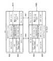
次に図2を参照して、本実施の形態に係る印刷装置の制御に係る主要部の構成を説明する。
【0024】
図2において、3000は制御部(制御基板)を示している。3001はASIC(専用カスタムLSI)、3002はDSP(デジタル信号処理プロセッサ)で、内部にCPUを有し、各種制御処理及び、輝度信号(RGB)から濃度信号(CMYK)への変換、スケーリング、ガンマ変換、誤差拡散等の画像処理等を担当している。3003はメモリで、DSP3002のCPUの制御プログラムを記憶するプログラムメモリ3003a、及び実行時のプログラムを記憶するRAMエリア、画像データなどを記憶するメモリエリアを有している。3004はプリンタエンジンで、ここでは、複数色のカラーインクを用いてカラー画像を印刷するインクジェットプリンタのプリンタエンジンが搭載されている。3005はデジタルカメラ(DSC)3012を接続するためのポートとしてのUSBコネクタである。3006はビューワ1011を接続するためのコネクタである。3008はUSBハブ(USB HUB)で、この印刷装置がPC(外部コンピュータ)3010からの画像データに基づいて印刷を行う際には、PC3010からのデータをそのままスルーし、USB3021を介してプリンタエンジン3004に出力する。これにより、接続されているPC3010は、プリンタエンジン3004と直接、データや信号のやり取りを行って印刷を実行することができる(一般的なPCプリンタとして機能する)。
【0025】
1009はカードスロットで、ここにメモリカードを装着可能なアダプタが挿入され、このアダプタを介してメモリカードに記憶されている画像データを直接取り込んで印刷することができる。このメモリカード(PC)としては、例えばコンパクトフラッシュ(登録商標)メモリ、スマートメディア(登録商標)、メモリスティック(登録商標)等がある。1011はビューワ(液晶表示部)で、この印刷装置本体に着脱可能であり、PCカードに記憶されている画像の中からプリントしたい画像を検索する場合などに、1コマ毎の画像やインデックス画像などを表示するのに使用される。1012はデジタルカメラを接続するためのUSB端子である。また、この印刷装置の後面には、パーソナルコンピュータ(PC)を接続するためのUSBコネクタ1013が設けられている。
【0026】
3009は電源コネクタで、電源3011により、商用ACから変換された直流電圧を入力している。PC3010は一般的なパーソナルコンピュータ、3011は前述したメモリカード(PCカード)、3012はデジタルカメラ(DSC:Digital Still Camera)である。
【0027】
尚、この制御部3000とプリンタエンジン3004との間の信号のやり取りは、前述したUSB3021又はIEEE1284バス3022を介して行われる。
【0028】
本実施の形態においては、印刷装置とデジタルカメラとの間の通信制御を汎用ファイル、汎用フォーマットを用いて行い、インターフェースに依存しないNCDP(New Camera Direct Print)を用いる第2のタイプの場合を想定している。
【0029】
図4は、このNCDPの構成の一例を示す図である。
【0030】
同図において、600はUSBによるインターフェース、601はブルーツース(Bluetooth)によるインターフェースを示している。602はNCDPによるシステムを構築する際に組込まれるアプリケーションレイヤを示している。603は既存のプロトコル及びインターフェースを実行するためのレイヤで、ここではPTP(Picture Transfer Protocol),SCSI及びブルーツースのBIP(Basic Image Profile),USBインターフェース等が実装されている。本実施の形態に係るNCDPは、このようなプロトコルレイヤ等のアーキテクチャが実装されていて、その上にアプリケーションとして実装されることが前提である。ここでは印刷装置1000は、USBホスト、カメラ3012はUSBスレーブとして規定されており、図4に示すように、それぞれ同じNCDP構成となっている。
【0031】
次に、本実施の形態における動作について説明する。
【0032】
まずステップS1でスタートし、撮像装置としてのデジタルカメラ(DSC)3012と印刷装置1000との間の例えば有線接続により通信が自動的にスタートする(ステップS2)。次にステップS3で、カメラと印刷装置双方に前記NCDPが実装済みかどうかを判定し、実装済みであればNOとしてNCDPに移行するが、一方にNCDPが実装されていない場合には、MSC(MASS ATORAGE CLASS)による処理が行われる。即ち、このMSCモードではカメラ内のメモリを印刷装置側からアクセスすることはできるが、カメラのコントローラに対して印刷装置からアクセスすることはできない。例えば、従来タイプの印刷装置においては、前記のようなNCDPが実装されていないタイプが存在している。従って、このようなMSCタイプの印刷装置とNCDPタイプのカメラを接続した場合には、印刷ができなくなってしまったり、印刷ミスが発生する可能性があるが、本発明の実施の形態では、このような問題が発生しないように、初期通信によって、NCDPを使った撮像装置から外部処理装置の処理制御(印刷制御)が可能な第2のモードか否かをチェックするように構成している。また、NCDPによる整合が取れない場合には、MSCとしての印刷制御(即ち、外部処理装置から撮像装置のメモリに直接アクセスする第1のモードであると判別し、撮像装置内の画像データを引き出し、その後印刷するよう手順)に自動的に切り換えるように構成されているので、上記のような問題が発生しない。また、操作者が操作ミスをしたり、迷ったりする煩雑さも発生しない。
【0033】
なお、このようなMSCの場合には、ステップS4において、カメラのモニターを省エネモードに移行させ、カメラのモニターを完全にオフにするか、あるいは「プリンタを操作してください。」という表示を行うと共に、画像表示等は消す。
【0034】
また、これに伴って、プリンタ側のモニターをオンする。
【0035】
次にプリンタ側に設けた画像転送スイッチがオンされたか否かをステップS5において確認する。
【0036】
ステップS5において、画像転送スイッチがオンされたことを検出するとステップS6に進み、カメラ内の画像データをプリンタに転送し、プリンタ装置内のメモリにカメラからの画像データを一括転送する。これは、カメラ内の画像データを一括転送した方が、カメラのバッテリのダウンによる問題を回避できるからである。
【0037】
次いで、プリンタ側のモニターに転送されてきた複数の画像を検索用にサムネール表示する。
【0038】
そして、ステップS7において、プリント画像の指定を待つと共に、プリントスイッチが押されるのを待つ。プリントスイッチがオンされると、ステップS8において指定された画像のプリント動作が行われる。なお、ステップS8におけるプリント動作が完了すると、ステップS7に再び戻る。
【0039】
ステップS3において、NCDPが双方に実装されていることが検出された場合にはステップS9に進み、カメラモニターに「プリント操作をしてください。」という表示を出すと共に、印刷装置側のモニターを省エネモードに移行する。そしてステップS10でカメラ側の転送スイッチがオンするのを待ち、オンしたらステップS11でカメラ内画像データをプリンタに転送する。
【0040】
その後ステップS12でカメラ側でプリントすべき画像を指定した後、カメラ側のプリントスイッチが押されるのを待つ。カメラ側のプリントスイッチがオンされると、ステップS13において、印刷装置にコマンドまたはファイル形式で印刷の指示が送信され、印刷装置で指定画像のプリント動作が行われる。なお、ステップS13におけるプリント動作が完了すると、ステップS12に戻る。
【0041】
なお本発明は、他の外部処理装置(例えばホストコンピュータ、インターフェース機器、リーダ、プリンタなど)と撮像装置(例えばデジタルカメラ、カムコーダ、スキャナ、複写機、ファクシミリ等)から構成されるシステムに適用してもよいし、複数の外部処理装置と撮像装置との組み合わせにおいても適用できる。
【0042】
また、本発明は前述のようなフローチャートによる処理を実現するソフトウェアのプログラムコードを記録した記憶媒体(または記録媒体)を、システムあるいは装置に供給し、そのシステムあるいは装置のコンピュータ(またはCPUやMPU)が記憶媒体に格納されたプログラムコードを読み出し実行することによっても達成される。この場合、記憶媒体から読み出されたプログラムコード自体が前述した実施形態の機能を実現することになり、そのプログラムコードを記憶した記憶媒体は本発明を構成することになる。また、コンピュータが読み出したプログラムコードを実行することにより、前述した実施形態の機能が実現されるだけでなく、そのプログラムコードの指示に基づき、コンピュータ上で稼働しているオペレーティングシステム(OS)などが実際の処理の一部または全部を行い、その処理によって前述した実施形態の機能が実現される場合も含まれる。
【0043】
さらに、記憶媒体から読み出されたプログラムコードが、コンピュータに挿入された機能拡張カードやコンピュータに接続された機能拡張ユニットに備わるメモリに書込まれた後、そのプログラムコードの指示に基づき、その機能拡張カードや機能拡張ユニットに備わるCPUなどが実際の処理の一部または全部を行い、その処理によって前述した実施形態の機能が実現される場合も含まれる。
【0044】
【発明の効果】
以上説明したように本発明によれば、撮像装置に直接印刷装置等の外部処理装置を接続し制御して簡単に撮影画像の印刷等の処理(他の処理としては、画像編集等も含まれる。)が実施できるので撮像装置固有の特徴である携帯性を活かした撮影、検索、プリント環境を実現できる。
【0045】
また、異なるタイプの撮像装置と外部処理装置の組み合わせにおいても、最適な処理の自動制御が可能になる。従って、操作ミス等が発生せず操作性が大幅に向上するという効果を有する。
【図面の簡単な説明】
【図1】本発明の実施の形態に係る撮像装置と外部処理装置からなるシステム構成例を示すブロック図である。
【図2】本発明の実施の形態に係る撮像装置と印刷装置のソフトウエア構成を示す説明図である。
【図3】本発明の実施の形態の印刷装置の構成を示す図である。
【図4】本発明の実施の形態の撮像装置と印刷装置間のプロトコルおよび両装置における処理の流れを示すフローチャートである。[0001]
BACKGROUND OF THE INVENTION
The present invention relates to an imaging apparatus, an external processing apparatus, a control program for the imaging apparatus, and a control program for the external processing apparatus.
[0002]
[Prior art]
Conventionally, in order to print a captured image with a digital imaging device such as a digital camera, the image data is once downloaded to a computer such as a personal computer and connected to the computer using an application for printing the image. I am doing work to output to the printer.
[0003]
In the above technique, a user searches for image list information and file names based on information displayed on a display by an application on a computer, and performs printing by selecting output data. On the other hand, recently, a color print system capable of directly printing digital image data from a digital camera to a color printer without using a PC, and a built-in digital camera, storing captured images. A so-called photo direct (PD) printer has been developed, in which a memory card is directly attached to a color printer and a photographed image stored in the memory card can be printed.
[0004]
[Problems to be solved by the invention]
However, when image data is directly transmitted from a digital camera to a printer for printing, the specifications and operation methods of the digital camera differ from manufacturer to manufacturer. The appearance of is desired. As described above, in a printer apparatus that directly connects and prints digital cameras of each manufacturer, it is necessary to match the print information arbitrarily set in each camera with the print conditions in the printer apparatus.
[0005]
The present invention has been made to solve the above-described conventional problems, and is an image pickup apparatus or an external processing apparatus that can perform shooting taking advantage of portability and can easily perform processing such as printing of a shot image by an external processing apparatus. It is intended to provide.
[0006]
Another object of the present invention is to automatically recognize an external processing device when transferring an image signal by connecting the imaging device and the external processing device by wire or wirelessly, and printing the external processing device in an optimum mode. It is an object of the present invention to provide an imaging device or an external processing device that can be controlled so as to be able to perform the above processing.
[0007]
[Means for Solving the Problems]
In order to solve this problem, for example, the imaging device of the first invention has the following configuration.
[0008]
That is, an imaging unit that converts a light image of a subject into an electrical image signal, an interface that can communicate with an externalprocessing device, and a control unit that transfers the image signal to the external processing device for processing. The control unit communicates with the external processing device via the interface, so that the control relationship between the imaging device and the external processing device directly accesses the memory inside the imaging device from the external processing device. Determining means for determining whether the first type is a second type capable of controlling the processing in the external processing device by a controller of the imaging device, and the image inside the imaging device is determined based on the determination result And a processing control means for changing a processing procedure for processing by an external processing device.
[0009]
An external processing device according to another invention is an external processing device that communicates with an imaging device including an interface capable of converting a light image of a subject into an electrical image signal and capable of communicating with the external processing device. By communicating with the imaging device via the interface, the control relationship between the imaging device and the external processing device is the first type in which the memory inside the imaging device is directly accessed from the external processing device, or the external processing device is controlled by the imaging device. Determining means for determining whether it is the second type capable of controlling the processing in the processing, and processing control means for changing the processing procedure for processing the image inside the imaging device by the external processing device based on the determination result It is characterized by having.
[0010]
According to another aspect of the present invention, there is provided a control program for an imaging device, an imaging unit that converts a light image of a subject into an electrical image signal, an interface that can communicate with an externalprocessing device, and the externalprocessing device thatprocesses the image signal. A control program for an imaging apparatus comprising control means for transferring to the apparatus for processing, wherein the control program communicates with the external processing apparatus via the interface to thereby obtain the imaging apparatus and the external processing apparatus Is determined to be the first type in which the memory in the imaging apparatus is directly accessed from the external processing apparatus or the second type in which the process in the external processing apparatus can be controlled by the controller of the imaging apparatus. A determination step and a process for processing an image inside the imaging device by the external processing device based on a result of the determination step And having a process control step of changing the order.
[0011]
According to another aspect of the invention, there is provided a control program for an external processing device that converts an optical image of a subject into an electrical image signal and communicates with an imaging device having an interface capable of communicating with the external processing device. And a control program for communicating with the imaging device via the interface, whereby a control relationship between the imaging device and the external processing device directly accesses a memory inside the imaging device from the external processing device. A discrimination step for discriminating between a type and a second type in which processing in the external processing device can be controlled by the imaging device, and an image inside the imaging device based on a result of the discrimination step by the external processing device And a process control step of changing a process procedure for processing.
[0012]
DETAILED DESCRIPTION OF THE INVENTION
DESCRIPTION OF EMBODIMENTS Hereinafter, preferred embodiments of the present invention will be described in detail with reference to the accompanying drawings.
[0013]
FIG. 1 is a block diagram showing a system configuration in an embodiment of the present invention.
[0014]
In the configuration example of the imaging and printing system of the present embodiment shown in FIG. 1, the imaging apparatus (for example, digital camera)
[0015]
The user interface component group 10-i includes a display unit (liquid crystal display unit) for displaying captured images and simple messages, a shutter button to be pressed when shooting, and a printing button. Various buttons such as a print button and a button for selecting a menu item displayed on the display unit are provided.
[0016]
The imaging apparatus
[0017]
The memory 10-e is detachable from a module 10-f that manages a communication protocol with the
[0018]
In the above configuration, by pressing a shutter button provided in the UI component group 10-i, video data captured by the imaging unit 10-a is stored as a file in the external storage device 10-1 as digital image data. The
[0019]
In this embodiment, when storing in the external storage device 10-1, image data obtained by photographing is compressed and stored in the JPEG format.
[0020]
On the other hand, the
[0021]
In this embodiment, the system management module 10-n in the memory 10-e always sends messages from the imaging system 10-a, internal device interface 10-j, external device interface 10-k, and user interface 10-h. I manage. In addition, the communication protocol management module 10-f manages signals input / output to / from the external device interface 10-k, that is, communication with the
[0022]
The communication system for connecting between the imaging apparatus
[0023]
Next, with reference to FIG. 2, the structure of the principal part which concerns on control of the printing apparatus which concerns on this Embodiment is demonstrated.
[0024]
In FIG. 2,
[0025]
[0026]
[0027]
Note that the exchange of signals between the
[0028]
In this embodiment, communication control between a printing apparatus and a digital camera is performed using a general-purpose file and a general-purpose format, and a case of the second type using NCDP (New Camera Direct Print) independent of an interface is assumed. is doing.
[0029]
FIG. 4 is a diagram showing an example of the configuration of this NCDP.
[0030]
In the figure, 600 indicates an interface by USB, and 601 indicates an interface by Bluetooth.
[0031]
Next, the operation in this embodiment will be described.
[0032]
First, in step S1, communication is automatically started by, for example, a wired connection between a digital camera (DSC) 3012 serving as an imaging apparatus and the printing apparatus 1000 (step S2). Next, in step S3, it is determined whether or not the NCDP is mounted on both the camera and the printing apparatus. If the NCDP is mounted, the process proceeds to NCDP as NO, but if NCDP is not mounted on one side, the MSC ( MASS ATORAGE CLASS) is performed. That is, in this MSC mode, the memory in the camera can be accessed from the printing apparatus side, but the camera controller cannot be accessed from the printing apparatus. For example, in a conventional type printing apparatus, there is a type in which the NCDP is not mounted as described above. Therefore, when such an MSC type printing apparatus and an NCDP type camera are connected, printing may be disabled or a printing error may occur. In the embodiment of the present invention, In order to prevent such a problem from occurring, it is configured to check whether or not it is the second mode in which processing control (printing control) of the external processing apparatus can be performed from the imaging apparatus using NCDP by initial communication. Further, if the NCDP cannot match, the print control as the MSC (that is, it is determined that the first mode is to directly access the memory of the imaging device from the external processing device, the image data in the imaging device is extracted, Thereafter, it is configured to automatically switch to the procedure of printing), so that the above problem does not occur. Further, there is no trouble that the operator makes an operation mistake or gets lost.
[0033]
In the case of such an MSC, in step S4, the camera monitor is shifted to the energy saving mode and the camera monitor is completely turned off, or the message “Please operate the printer.” Is displayed. At the same time, the image display and the like are turned off.
[0034]
Along with this, the printer monitor is turned on.
[0035]
Next, in step S5, it is confirmed whether the image transfer switch provided on the printer side is turned on.
[0036]
In step S5, when it is detected that the image transfer switch is turned on, the process proceeds to step S6, where the image data in the camera is transferred to the printer, and the image data from the camera is transferred to the memory in the printer device at once. This is because transferring the image data in the camera at once can avoid the problem caused by the battery of the camera being down.
[0037]
Next, a plurality of images transferred to the printer monitor are displayed as thumbnails for retrieval.
[0038]
In step S7, the printer waits for designation of a print image and waits for the print switch to be pressed. When the print switch is turned on, an image printing operation designated in step S8 is performed. When the printing operation in step S8 is completed, the process returns to step S7 again.
[0039]
If it is detected in step S3 that the NCDP is installed on both sides, the process proceeds to step S9, where the message “Please perform printing operation” is displayed on the camera monitor, and the monitor on the printing apparatus side is saved. Enter mode. In step S10, it waits for the transfer switch on the camera side to be turned on, and when it is turned on, in-camera image data is transferred to the printer in step S11.
[0040]
In step S12, the camera side designates an image to be printed, and then waits for the camera side print switch to be pressed. When the print switch on the camera side is turned on, in step S13, a printing instruction is transmitted to the printing apparatus in a command or file format, and the printing operation of the designated image is performed in the printing apparatus. When the printing operation in step S13 is completed, the process returns to step S12.
[0041]
The present invention is applied to a system composed of another external processing device (for example, a host computer, interface device, reader, printer, etc.) and an imaging device (for example, a digital camera, camcorder, scanner, copying machine, facsimile, etc.). Alternatively, the present invention can be applied to a combination of a plurality of external processing devices and imaging devices.
[0042]
Further, the present invention supplies a storage medium (or recording medium) that records software program codes for realizing the processing according to the flowchart as described above to a system or apparatus, and a computer (or CPU or MPU) of the system or apparatus. Is also achieved by reading and executing the program code stored in the storage medium. In this case, the program code itself read from the storage medium realizes the functions of the above-described embodiments, and the storage medium storing the program code constitutes the present invention. Further, by executing the program code read by the computer, not only the functions of the above-described embodiments are realized, but also an operating system (OS) running on the computer based on the instruction of the program code. A case where part or all of the actual processing is performed and the functions of the above-described embodiments are realized by the processing is also included.
[0043]
Furthermore, after the program code read from the storage medium is written into a memory provided in a function expansion card inserted into the computer or a function expansion unit connected to the computer, the function is determined based on the instruction of the program code. The case where the CPU of the expansion card or the function expansion unit performs part or all of the actual processing and the functions of the above-described embodiments are realized by the processing is also included.
[0044]
【The invention's effect】
As described above, according to the present invention, an external processing device such as a printing device is directly connected to and controlled by the imaging device, and processing such as printing of a captured image is easily performed (other processing includes image editing and the like). )) Can be implemented, it is possible to realize a shooting, search, and print environment that takes advantage of portability, which is a characteristic unique to an imaging apparatus.
[0045]
In addition, even in a combination of different types of imaging devices and external processing devices, automatic control of optimum processing becomes possible. Therefore, there is an effect that operability is greatly improved without causing an operation error or the like.
[Brief description of the drawings]
FIG. 1 is a block diagram illustrating a system configuration example including an imaging apparatus and an external processing apparatus according to an embodiment of the present invention.
FIG. 2 is an explanatory diagram showing a software configuration of an imaging apparatus and a printing apparatus according to an embodiment of the present invention.
FIG. 3 is a diagram illustrating a configuration of a printing apparatus according to an embodiment of the present invention.
FIG. 4 is a flowchart illustrating a protocol between the imaging apparatus and the printing apparatus according to the embodiment of the present invention and a processing flow in both apparatuses.
Claims (27)
Translated fromJapanese前記制御手段は、
前記インターフェースを介して前記外部処理装置と通信することによって撮像装置と外部処理装置の制御関係が、撮像装置内部のメモリを前記外部処理装置から直接アクセスする第1のタイプか、撮像装置のコントローラにより前記外部処理装置における処理を制御することが可能な第2のタイプかを判別する判別手段と、
該判別結果に基づき前記撮像装置内部の画像を前記外部処理装置により処理するための処理手順を変更する処理制御手段と、
を有することを特徴とする撮像装置。An imaging unit that converts a light image of a subject into an electrical image signal, an interface that can communicate with an externalprocessing device, and a control unit that transfers the image signal to the external processing device for processing. An imaging device comprising:
The control means includes
The control relationship between the imaging apparatus and the external processing apparatus by communicating with the external processing apparatus via the interface is a first type in which the memory inside the imaging apparatus is directly accessed from the external processing apparatus, or the controller of the imaging apparatus Determining means for determining whether the second type is capable of controlling processing in the external processing device;
Processing control means for changing a processing procedure for processing an image inside the imaging apparatus by the external processing device based on the determination result;
An imaging device comprising:
前記インターフェースを介して前記撮像装置と通信することによって、撮像装置と外部処理装置の制御関係が、撮像装置内部のメモリを前記外部処理装置から直接アクセスする第1のタイプか、撮像装置により前記外部処理装置における処理を制御することが可能な第2のタイプかを判別する判別手段と、
該判別結果に基づき前記撮像装置内部の画像を前記外部処理装置により処理するための処理手順を変更する処理制御手段と、
を有することを特徴とする外部処理装置。An external processing device that communicates with an imaging device that includes an interface capable of converting a light image of a subject into an electrical image signal and communicating with the external processing device,
By communicating with the imaging device via the interface, the control relationship between the imaging device and the external processing device is the first type in which the memory inside the imaging device is directly accessed from the external processing device, or the external processing by the imaging device. Discrimination means for discriminating whether the second type is capable of controlling processing in the apparatus;
Processing control means for changing a processing procedure for processing an image inside the imaging apparatus by the external processing device based on the determination result;
An external processing device comprising:
前記制御プログラムは前記インターフェースを介して前記外部処理装置と通信することによって撮像装置と外部処理装置の制御関係が、撮像装置内部のメモリを前記外部処理装置から直接アクセスする第1のタイプか、撮像装置のコントローラにより前記外部処理装置における処理を制御することが可能な第2のタイプかを判別する判別ステップと、
該判別ステップの結果に基づき前記撮像装置内部の画像を前記外部処理装置により処理するための処理手順を変更する処理制御ステップと、
を有することを特徴とする撮像装置のための制御プログラム。An imaging unit that converts a light image of a subject into an electrical image signal, an interface that can communicate with an externalprocessing device, and a control unit that transfers the image signal to the external processing device for processing. A control program for an imaging apparatus,
The control program communicates with the external processing device via the interface, so that the control relationship between the imaging device and the external processing device is a first type in which the internal memory of the imaging device is directly accessed from the external processing device, or the imaging device A determination step of determining whether the second type is capable of controlling the processing in the external processing device by the controller;
A process control step for changing a processing procedure for processing an image inside the imaging apparatus by the external processing device based on a result of the determination step;
A control program for an imaging apparatus, comprising:
前記インターフェースを介して前記撮像装置と通信することによって、撮像装置と外部処理装置の制御関係が、撮像装置内部のメモリを前記外部処理装置から直接アクセスする第1のタイプか、撮像装置により前記外部処理装置における処理を制御することが可能な第2のタイプかを判別する判別ステップと、
該判別ステップの結果に基づき前記撮像装置内部の画像を前記外部処理装置により処理するための処理手順を変更する処理制御ステップと、
を有することを特徴とする外部処理装置のための制御プログラム。A control program for an external processing device that communicates with an imaging device having an interface that converts an optical image of a subject into an electrical image signal and is capable of communicating with the external processing device,
By communicating with the imaging device via the interface, the control relationship between the imaging device and the external processing device is the first type in which the memory inside the imaging device is directly accessed from the external processing device, or the external processing by the imaging device. A discriminating step for discriminating whether the second type is capable of controlling processing in the apparatus;
A process control step for changing a processing procedure for processing an image inside the imaging apparatus by the external processing device based on a result of the determination step;
A control program for an external processing device, comprising:
Priority Applications (5)
| Application Number | Priority Date | Filing Date | Title |
|---|---|---|---|
| JP2002207363AJP3809403B2 (en) | 2002-07-16 | 2002-07-16 | Imaging device, external processing device, control program for imaging device, control program for external processing device |
| EP03254307.6AEP1383302B1 (en) | 2002-07-16 | 2003-07-07 | Image storage apparatus, external image processing apparatus, control method for image storage apparatus and control method for external image processing apparatus |
| CNB031460704ACN1241402C (en) | 2002-07-16 | 2003-07-15 | Image storage equipment, external image processing equipment and its control method |
| KR1020030048378AKR100550136B1 (en) | 2002-07-16 | 2003-07-15 | Image storage apparatus, external image processing apparatus, control method for image storage apparatus and control method for external image processing apparatus |
| US10/620,897US7719699B2 (en) | 2002-07-16 | 2003-07-15 | Image storage apparatus, external image processing apparatus, control method for image storage apparatus and control method for external image processing apparatus |
Applications Claiming Priority (1)
| Application Number | Priority Date | Filing Date | Title |
|---|---|---|---|
| JP2002207363AJP3809403B2 (en) | 2002-07-16 | 2002-07-16 | Imaging device, external processing device, control program for imaging device, control program for external processing device |
Publications (3)
| Publication Number | Publication Date |
|---|---|
| JP2004056220A JP2004056220A (en) | 2004-02-19 |
| JP2004056220A5 JP2004056220A5 (en) | 2005-10-27 |
| JP3809403B2true JP3809403B2 (en) | 2006-08-16 |
Family
ID=29774618
Family Applications (1)
| Application Number | Title | Priority Date | Filing Date |
|---|---|---|---|
| JP2002207363AExpired - Fee RelatedJP3809403B2 (en) | 2002-07-16 | 2002-07-16 | Imaging device, external processing device, control program for imaging device, control program for external processing device |
Country Status (5)
| Country | Link |
|---|---|
| US (1) | US7719699B2 (en) |
| EP (1) | EP1383302B1 (en) |
| JP (1) | JP3809403B2 (en) |
| KR (1) | KR100550136B1 (en) |
| CN (1) | CN1241402C (en) |
Families Citing this family (15)
| Publication number | Priority date | Publication date | Assignee | Title |
|---|---|---|---|---|
| JP4125173B2 (en) | 2003-04-23 | 2008-07-30 | キヤノン株式会社 | Information processing apparatus connection control method, information processing apparatus, and computer program |
| JP4136771B2 (en) | 2003-04-23 | 2008-08-20 | キヤノン株式会社 | COMMUNICATION SYSTEM, COMMUNICATION DEVICE, ITS CONTROL METHOD, AND COMPUTER PROGRAM |
| JP4125172B2 (en) | 2003-04-23 | 2008-07-30 | キヤノン株式会社 | Wireless communication system, wireless communication apparatus, control method therefor, and computer program |
| KR100612009B1 (en) | 2004-04-22 | 2006-08-11 | 삼성전자주식회사 | Direct image printing method and apparatus |
| JP4533005B2 (en)* | 2004-06-08 | 2010-08-25 | キヤノン株式会社 | Printing apparatus and printer control method |
| KR100601696B1 (en)* | 2004-07-27 | 2006-07-14 | 삼성전자주식회사 | Direct image processing method and apparatus |
| KR100886692B1 (en)* | 2004-09-16 | 2009-03-04 | 캐논 가부시끼가이샤 | File transmission apparatus and control method of the same and commumication system |
| KR101156113B1 (en)* | 2005-03-31 | 2012-06-20 | 삼성전자주식회사 | Method of controlling digital image processing apparatus for convenient communication, and digital image processing apparatus adopting the method |
| JP4618021B2 (en) | 2005-07-06 | 2011-01-26 | 富士ゼロックス株式会社 | Image reading apparatus, image forming apparatus, image processing system, storage area sharing method of image reading apparatus, and storage area sharing method of image processing system |
| JP4886463B2 (en) | 2006-10-20 | 2012-02-29 | キヤノン株式会社 | Communication parameter setting method, communication apparatus, and management apparatus for managing communication parameters |
| JP2010009521A (en) | 2008-06-30 | 2010-01-14 | Canon Inc | Image providing apparatus, image output apparatus, and image output system |
| JP4567078B2 (en)* | 2008-07-14 | 2010-10-20 | シャープ株式会社 | Image forming apparatus, image forming method, printer driver program, and image forming system |
| KR101008362B1 (en)* | 2009-03-06 | 2011-01-13 | 현대건설주식회사 | Sliding door structure |
| CN104943419B (en)* | 2014-03-24 | 2017-08-25 | 联想(北京)有限公司 | The method and printer of a kind of print data |
| DE102019107853B4 (en)* | 2019-03-27 | 2020-11-19 | Schölly Fiberoptic GmbH | Procedure for commissioning a camera control unit (CCU) |
Family Cites Families (37)
| Publication number | Priority date | Publication date | Assignee | Title |
|---|---|---|---|---|
| DE69123770T2 (en)* | 1990-03-23 | 1997-06-19 | Matsushita Electric Ind Co Ltd | Handheld data processing device with reduced power consumption |
| JP3410190B2 (en)* | 1993-12-29 | 2003-05-26 | 株式会社東芝 | Image forming apparatus and document reading method |
| JP3747108B2 (en)* | 1996-02-02 | 2006-02-22 | キヤノン株式会社 | Digital imaging apparatus and control method thereof |
| JP3832089B2 (en)* | 1997-05-26 | 2006-10-11 | セイコーエプソン株式会社 | Digital camera and printing system |
| AU695514B2 (en)* | 1996-06-25 | 1998-08-13 | Casio Computer Co., Ltd. | Printing apparatus and printing system |
| JP3986588B2 (en)* | 1996-09-12 | 2007-10-03 | ブラザー工業株式会社 | Image image forming system and scanner device |
| US6115137A (en)* | 1996-12-06 | 2000-09-05 | Canon Kabushiki Kaisha | Image processing system, digital camera, and printing apparatus |
| JP3877368B2 (en)* | 1997-01-30 | 2007-02-07 | オリンパス株式会社 | Digital printing system |
| JPH10226139A (en)* | 1997-02-14 | 1998-08-25 | Canon Inc | Image forming system, image forming apparatus, and medium |
| US6298405B1 (en)* | 1997-02-14 | 2001-10-02 | Canon Kabushiki Kaisha | Data communication system, printing system and data communication apparatus |
| EP0859323B1 (en)* | 1997-02-14 | 2007-03-21 | Canon Kabushiki Kaisha | Data transmission apparatus, system and method, and image processing apparatus |
| EP0864986B1 (en)* | 1997-03-12 | 2006-07-12 | Canon Kabushiki Kaisha | Data communication apparatus, method and system, and program for data communication process stored in memory medium |
| US6018816A (en)* | 1997-04-04 | 2000-01-25 | Canon Kabushiki Kaisha | Information processing system and method, image processing system and method, information processing apparatus and computer readable memory |
| JPH11127323A (en)* | 1997-10-21 | 1999-05-11 | Canon Inc | Image memory device, digital camera, image processing system, data processing method of image processing system, and storage medium storing computer readable program |
| US6552743B1 (en)* | 1998-04-08 | 2003-04-22 | Hewlett Packard Development Company, L.P. | Digital camera-ready printer |
| JP2000108468A (en)* | 1998-10-07 | 2000-04-18 | Fuji Photo Film Co Ltd | Printer |
| JP2000118086A (en) | 1998-10-14 | 2000-04-25 | Fuji Photo Film Co Ltd | Printing system and printing designating processing method |
| US6956671B2 (en)* | 1998-10-15 | 2005-10-18 | Hewlett-Packard Development Company, L.P. | Specifying image file processing operations via device controls and a user-completed proof sheet |
| JP2000134527A (en)* | 1998-10-26 | 2000-05-12 | Minolta Co Ltd | Digital camera |
| JP2000196986A (en)* | 1998-12-25 | 2000-07-14 | Olympus Optical Co Ltd | Electronic image pickup device |
| US6357021B1 (en)* | 1999-04-14 | 2002-03-12 | Mitsumi Electric Co., Ltd. | Method and apparatus for updating firmware |
| JP4046897B2 (en)* | 1999-06-30 | 2008-02-13 | キヤノン株式会社 | Image input apparatus and control method thereof |
| US6711637B2 (en)* | 2000-01-11 | 2004-03-23 | Canon Kabushiki Kaisha | Communication apparatus, image processing apparatus, communication system, communication method, image processing method and storage medium |
| JP4343373B2 (en)* | 2000-01-14 | 2009-10-14 | 富士フイルム株式会社 | Photo service system and digital camera |
| AUPQ724700A0 (en)* | 2000-05-02 | 2000-05-25 | Canon Kabushiki Kaisha | Printing using secure pickup |
| US6912060B1 (en)* | 2000-07-05 | 2005-06-28 | Lexmark International, Inc. | Photoprinter control of peripheral devices |
| US7262873B1 (en)* | 2000-07-05 | 2007-08-28 | Lexmark International, Inc. | Photoprinter access to remote data |
| JP2002074350A (en)* | 2000-08-29 | 2002-03-15 | Canon Inc | Image processing system, control method therefor, and image processing apparatus |
| JP4454819B2 (en)* | 2000-09-20 | 2010-04-21 | キヤノン株式会社 | Digital camera, control method of digital camera |
| JP2002183167A (en)* | 2000-12-14 | 2002-06-28 | Canon Inc | Data communication device and image storage system |
| JP3862507B2 (en)* | 2001-02-07 | 2006-12-27 | キヤノン株式会社 | Camera and control method thereof |
| JP2002281227A (en)* | 2001-03-21 | 2002-09-27 | Olympus Optical Co Ltd | Digital camera system and recycle system of camera |
| JP2002296983A (en)* | 2001-03-30 | 2002-10-09 | Minolta Co Ltd | Image processor |
| JP4193378B2 (en)* | 2001-06-27 | 2008-12-10 | セイコーエプソン株式会社 | Image file generator |
| JP4059027B2 (en)* | 2001-10-03 | 2008-03-12 | セイコーエプソン株式会社 | Printer and printer print condition setting method |
| JP2004005541A (en)* | 2002-04-16 | 2004-01-08 | Canon Inc | Data transfer device, data transfer method, program and recording medium |
| JP2004013349A (en)* | 2002-06-04 | 2004-01-15 | Canon Inc | Imaging device, recording system and recording control method thereof |
- 2002
- 2002-07-16JPJP2002207363Apatent/JP3809403B2/ennot_activeExpired - Fee Related
- 2003
- 2003-07-07EPEP03254307.6Apatent/EP1383302B1/ennot_activeExpired - Lifetime
- 2003-07-15KRKR1020030048378Apatent/KR100550136B1/ennot_activeExpired - Fee Related
- 2003-07-15CNCNB031460704Apatent/CN1241402C/ennot_activeExpired - Fee Related
- 2003-07-15USUS10/620,897patent/US7719699B2/ennot_activeExpired - Fee Related
Also Published As
| Publication number | Publication date |
|---|---|
| US7719699B2 (en) | 2010-05-18 |
| KR100550136B1 (en) | 2006-02-08 |
| CN1477861A (en) | 2004-02-25 |
| EP1383302B1 (en) | 2018-09-12 |
| CN1241402C (en) | 2006-02-08 |
| EP1383302A1 (en) | 2004-01-21 |
| KR20040010198A (en) | 2004-01-31 |
| JP2004056220A (en) | 2004-02-19 |
| US20040012805A1 (en) | 2004-01-22 |
Similar Documents
| Publication | Publication Date | Title |
|---|---|---|
| JP3840091B2 (en) | IMAGING DEVICE, SYSTEM HAVING IMAGING DEVICE AND RECORDING DEVICE AND CONTROL METHOD THEREOF | |
| US7595901B2 (en) | Imaging apparatus, system having imaging apparatus and printing apparatus, and control method therefor | |
| JP3809403B2 (en) | Imaging device, external processing device, control program for imaging device, control program for external processing device | |
| US7352392B2 (en) | Digital camera capable of outputting image data to external apparatus | |
| JP2004015234A (en) | PRINTING APPARATUS, CONTROL METHOD THEREOF, AND PRINTING SYSTEM | |
| US20050185205A1 (en) | Digital printer for transferring and printing images from a digital camera and a computer | |
| US7804520B2 (en) | Image sending and receiving system, image sending apparatus and image receiving apparatus | |
| JP2003143539A (en) | Imaging apparatus, system having imaging apparatus and recording apparatus, and control method therefor | |
| JP2004013348A (en) | Digital camera, control method thereof, and print system | |
| US20040169727A1 (en) | System and method for viewing and selecting images for printing | |
| JP2000118086A (en) | Printing system and printing designating processing method | |
| JP4196522B2 (en) | Information transmitting apparatus, information communication system, information transmitting method, information reproducing method, and computer-readable recording medium recording information transmitting program | |
| JP2004312367A (en) | Digital camera, data synchronizing system, data synchronizing method | |
| KR20060056997A (en) | Image supply apparatus and recording apparatus, recording system including these apparatuses, and communication control method in the recording system | |
| JP2001169159A (en) | Digital cameras and digital camera systems | |
| JP5008282B2 (en) | Imaging apparatus, control method therefor, computer program, and storage medium | |
| JP2004070610A (en) | Printer device, digital camera, and control program for digital camera | |
| JP2004066602A (en) | Recording system, control method thereof, and direct printing apparatus | |
| JP2000069341A (en) | Method for storing image pickup data and digital image pickup device and storage device used for the method | |
| JPH10271369A (en) | Accessory for digital camera | |
| JP5518127B2 (en) | Imaging apparatus, control method therefor, computer program, and storage medium | |
| JP2001111953A (en) | Image data recorder, printer, electronic camera and electronic album | |
| JP2006352361A (en) | Imaging device | |
| JP2004172840A (en) | Information recording system and information recording service system | |
| JP2001333306A (en) | Digital camera and print system using the camera |
Legal Events
| Date | Code | Title | Description |
|---|---|---|---|
| A521 | Written amendment | Free format text:JAPANESE INTERMEDIATE CODE: A523 Effective date:20050719 | |
| A621 | Written request for application examination | Free format text:JAPANESE INTERMEDIATE CODE: A621 Effective date:20050719 | |
| A977 | Report on retrieval | Free format text:JAPANESE INTERMEDIATE CODE: A971007 Effective date:20060419 | |
| TRDD | Decision of grant or rejection written | ||
| A01 | Written decision to grant a patent or to grant a registration (utility model) | Free format text:JAPANESE INTERMEDIATE CODE: A01 Effective date:20060428 | |
| A61 | First payment of annual fees (during grant procedure) | Free format text:JAPANESE INTERMEDIATE CODE: A61 Effective date:20060522 | |
| R150 | Certificate of patent or registration of utility model | Free format text:JAPANESE INTERMEDIATE CODE: R150 Ref document number:3809403 Country of ref document:JP Free format text:JAPANESE INTERMEDIATE CODE: R150 | |
| FPAY | Renewal fee payment (event date is renewal date of database) | Free format text:PAYMENT UNTIL: 20100526 Year of fee payment:4 | |
| FPAY | Renewal fee payment (event date is renewal date of database) | Free format text:PAYMENT UNTIL: 20100526 Year of fee payment:4 | |
| FPAY | Renewal fee payment (event date is renewal date of database) | Free format text:PAYMENT UNTIL: 20110526 Year of fee payment:5 | |
| FPAY | Renewal fee payment (event date is renewal date of database) | Free format text:PAYMENT UNTIL: 20120526 Year of fee payment:6 | |
| FPAY | Renewal fee payment (event date is renewal date of database) | Free format text:PAYMENT UNTIL: 20120526 Year of fee payment:6 | |
| FPAY | Renewal fee payment (event date is renewal date of database) | Free format text:PAYMENT UNTIL: 20130526 Year of fee payment:7 | |
| FPAY | Renewal fee payment (event date is renewal date of database) | Free format text:PAYMENT UNTIL: 20140526 Year of fee payment:8 | |
| LAPS | Cancellation because of no payment of annual fees |