JP3808160B2 - Plastic bottle - Google Patents
Plastic bottleDownload PDFInfo
- Publication number
- JP3808160B2 JP3808160B2JP05095397AJP5095397AJP3808160B2JP 3808160 B2JP3808160 B2JP 3808160B2JP 05095397 AJP05095397 AJP 05095397AJP 5095397 AJP5095397 AJP 5095397AJP 3808160 B2JP3808160 B2JP 3808160B2
- Authority
- JP
- Japan
- Prior art keywords
- wall
- variable
- rib
- bottle
- ribs
- Prior art date
- Legal status (The legal status is an assumption and is not a legal conclusion. Google has not performed a legal analysis and makes no representation as to the accuracy of the status listed.)
- Expired - Fee Related
Links
- 239000004033plasticSubstances0.000titleclaimsdescription17
- 229920003023plasticPolymers0.000titleclaimsdescription17
- 230000002093peripheral effectEffects0.000claimsdescription31
- 238000007664blowingMethods0.000claimsdescription5
- 238000011038discontinuous diafiltration by volume reductionMethods0.000description31
- 230000000694effectsEffects0.000description8
- 230000005489elastic deformationEffects0.000description8
- 229920005989resinPolymers0.000description7
- 239000011347resinSubstances0.000description7
- 239000000463materialSubstances0.000description6
- 238000005452bendingMethods0.000description4
- 238000003825pressingMethods0.000description4
- 238000010586diagramMethods0.000description3
- 238000000465mouldingMethods0.000description3
- 238000000071blow mouldingMethods0.000description2
- 230000000994depressogenic effectEffects0.000description2
- 238000002474experimental methodMethods0.000description2
- 238000004519manufacturing processMethods0.000description2
- 230000000630rising effectEffects0.000description2
- 230000032258transportEffects0.000description2
- 239000004698PolyethyleneSubstances0.000description1
- 235000013361beverageNutrition0.000description1
- 238000010101extrusion blow mouldingMethods0.000description1
- 229920001903high density polyethylenePolymers0.000description1
- 239000004700high-density polyethyleneSubstances0.000description1
- 230000001771impaired effectEffects0.000description1
- 238000000034methodMethods0.000description1
- 230000002787reinforcementEffects0.000description1
- 238000007789sealingMethods0.000description1
- 229920003002synthetic resinPolymers0.000description1
- 239000000057synthetic resinSubstances0.000description1
- 239000002699waste materialSubstances0.000description1
Images


Classifications
- B—PERFORMING OPERATIONS; TRANSPORTING
- B65—CONVEYING; PACKING; STORING; HANDLING THIN OR FILAMENTARY MATERIAL
- B65D—CONTAINERS FOR STORAGE OR TRANSPORT OF ARTICLES OR MATERIALS, e.g. BAGS, BARRELS, BOTTLES, BOXES, CANS, CARTONS, CRATES, DRUMS, JARS, TANKS, HOPPERS, FORWARDING CONTAINERS; ACCESSORIES, CLOSURES, OR FITTINGS THEREFOR; PACKAGING ELEMENTS; PACKAGES
- B65D1/00—Rigid or semi-rigid containers having bodies formed in one piece, e.g. by casting metallic material, by moulding plastics, by blowing vitreous material, by throwing ceramic material, by moulding pulped fibrous material or by deep-drawing operations performed on sheet material
- B65D1/02—Bottles or similar containers with necks or like restricted apertures, designed for pouring contents
- B65D1/0223—Bottles or similar containers with necks or like restricted apertures, designed for pouring contents characterised by shape
- B65D1/0292—Foldable bottles
- B—PERFORMING OPERATIONS; TRANSPORTING
- B29—WORKING OF PLASTICS; WORKING OF SUBSTANCES IN A PLASTIC STATE IN GENERAL
- B29C—SHAPING OR JOINING OF PLASTICS; SHAPING OF MATERIAL IN A PLASTIC STATE, NOT OTHERWISE PROVIDED FOR; AFTER-TREATMENT OF THE SHAPED PRODUCTS, e.g. REPAIRING
- B29C49/00—Blow-moulding, i.e. blowing a preform or parison to a desired shape within a mould; Apparatus therefor
- B29C49/42—Component parts, details or accessories; Auxiliary operations
- B29C49/4273—Auxiliary operations after the blow-moulding operation not otherwise provided for
- B29C49/4283—Deforming the finished article
Landscapes
- Engineering & Computer Science (AREA)
- Ceramic Engineering (AREA)
- Mechanical Engineering (AREA)
- Containers Having Bodies Formed In One Piece (AREA)
Description
Translated fromJapanese【0001】
【発明の属する技術分野】
本発明は、変形、復元可能とした容器、とくに弾性限度内で変形、復元可能とし、減容して運搬できるようにしたプラスチックボトルに関する。
【0002】
【発明が解決しようとする課題】
ブロー成形ボトルの利用にあたっては、飲料、各種家庭用品等、内容物の製造メーカーは、容器メーカーからボトルを購入し、充填工場でボトルに内容物を充填し、包装を施した上で製品として出荷している。
そのため、容器メーカーは、成形工場でブロー成形されたボトルを箱詰めにして内容物充填工場に輸送している。
【0003】
ボトルのブロー成形に引き続いて内容物を充填する「ブローフィルシール法」も知られているが、容器製造と内容物製造とは専業化されており、内容物の製造メーカーはボトルまで成形することは少なく、一般には、成形工場でブロー成形されたボトルを内容物充填工場に輸送することが多く行われている。
【0004】
しかしながら、成形工場から充填工場への空ボトルの輸送は、重量こそ軽量であるが、容積が嵩張り一回に運ばれる個数が少なく、輸送効率はきわめて低かった。
さらに、ボトルが円形であると、直交する二軸方向にボトルを相互に接合するよう整列させて箱詰めするからボトル間の空間容積が増え、積載効力は一層低下した。
【0005】
本発明は、上記の事情に鑑み、ボトルの容積を一時的に減容させて積載輸送効率を高めることを技術的課題として、成形ボトルを、素材樹脂の弾性変形の限度内で反転変形、復元可能としたプラスチックボトルを提供することを目的とする。
【0006】
【課題を解決するための手段】
上記の技術的課題は、ボトルの胴部壁面に、所定の平面から膨出し弾性変形の範囲内で変形復元可能な可変部を形成し、その他の部分を形状不変部とし、可変面をスナップ動作により前記所定の平面からボトル内方に反転させ、反転変形状態を維持することによって達成することができる。
【0007】
本発明は、技術的課題を達成するために、プラスチックボトルとして、ボトルの胴部壁面に、折れ部を形成し、弾性変形する可変リブを配設して可変面を形成し、前記可変面を、可変リブによって形成される平面に対して、形状不変面側にスナップ動作により反転させ、反転状態を維持するようにしたプラスチックボトルにおいて、可変リブの断面が、厚肉の中央部と薄肉の両側部からなり、側部の端縁を胴部壁面と丸みをもって連結し、可変リブが弾性限度内で湾曲変形するようにしたことを特徴とする構成を採用する。
成形ボトルの減容は、減容率10%〜45%に減容するようにする。
【0008】
ボトルの形状に応じて、円形ボトルにおける技術手段として、球帯状の肩壁と円筒状の胴壁、球帯状の下部周壁とからなる胴部を備えた円形ボトルであって、球帯状の肩壁と下部周壁に、上下に対向する位置にほぼ半円形に延びる可変リブを配設し、該可変リブは、その断面が、厚肉の中央部と薄肉の両側部からなり、側部の端縁を胴部壁面と丸みをもって連結し、弾性限度内で湾曲変形するようにされたリブであって、該可変リブによって形成される平面に対して、該平面より膨出する胴壁を可変面とし、該可変面を弾性限度内において、スナップ動作により反転変形、復元可能としたことを可能とする構成を採用する。
【0009】
また、ボトルが胴長になる場合に、球帯状の肩壁と円筒状の胴壁、球帯状の下部周壁とからなる胴部を備えた円形ボトルにおいては、球帯状の肩壁と下部周壁に、上下に対向する位置にほぼ半円形の円弧状可変リブを配設し、円筒状の胴壁内に前記上下の円弧状可変リブの両端縁のそれぞれを結ぶ可変縦リブを配設し、前記円弧状可変リブ、可変縦リブは、その断面が、厚肉の中央部と薄肉の両側部からなり、側部の端縁が胴部壁面と丸みをもって連結し、弾性限度内で湾曲変形するようにされたリブであって、前記円弧状可変リブと二つの可変縦リブによって形成される平面に対して、該平面より膨出する胴部周壁を可変面とし、該可変面を弾性限度内において、スナップ動作により反転変形、復元可能としたことを特徴とする構成を採用し、必要に応じて、球帯状の肩壁と下部周壁、または円筒状の胴壁内に、可変縦リブを連結する可変横リブを架設する。
【0010】
角壁を有する円形ボトルにおいては、口筒部と角壁を有する胴部をを備えた円形ボトルであって、前記胴部は、口筒部に続く球帯状の肩壁と、前記肩壁に続く角壁と、該角壁の表面から膨出するよう形成され、上下を球帯壁とし、中間部を円筒壁とした膨出部とを具え、前記膨出部の中央に、上部球帯壁、円筒壁、下部球帯壁にわたって上下に可変縦リブを配設し、上下の球帯壁に前記可変縦リブに交差する所定長さの可変横リブを配設し、前記可変縦リブと可変横リブは、その断面が、厚肉の中央部と薄肉の両側部からなり、側部の端縁が膨出部壁面と丸みをもって連結し、弾性限度内で湾曲変形するようにされたリブであって、膨出部の壁面が角壁面に対してスナップ動作により反転変形、復元可能としたことを特徴とする構成を採用する。
【0011】
また角形ボトルの場合には、口筒部と、口筒部に連続する肩壁と多角筒壁とからなる胴部と、四角形の底部を備えたボトルであって、前記多角筒壁は、前後に対向して平行に配設された長方形の平壁と、肩壁に連続し左右の側部に平行に対向して配設された等脚台形の側壁と、平壁と側壁との間に配設されたほぼ台形の側部傾斜壁と、前記肩壁と平壁および側部傾斜壁の各端縁の間に配設された上部傾斜壁と、底壁と平壁および側部傾斜壁の各端縁との間に配設された下部傾斜壁とを具備しており、平壁と側部傾斜壁の接続部に可変縦リブを配設し、平壁と上部傾斜壁との接続部および平壁と下部傾斜壁との接続部に可変横リブを配設し、上部傾斜壁の側端縁と側部傾斜壁の上端縁との間、および下部傾斜壁の側端縁と側部傾斜壁の下端縁との間に三角状可変リブを配設し、平壁と各傾斜壁によって形成される可変面が、肩壁と側壁および底壁によって形成される不変面に対して、弾性限度内においてスナップ動作により反転変形、復元可能としたことを特徴とする構成を採用し、三角状可変リブが、平壁の角部円弧縁からリブの長手方向に突出する膨出壁と傾斜壁の対向する端縁との間を連結するリブ底壁とからなり、リブ底壁が、舟底形のリブ主部と、膨出壁とによって分岐された二つの分岐部とを具備し、各分岐部は、対応する可変縦リブまたは可変横リブに連続していることを特徴とする構成を採用する。
変形減容ボトルのの復元は、ボトルの口筒部より圧縮空気を吹き込むことによって復元するようにしたことを特徴とする。
【0012】
【発明の実施の形態】
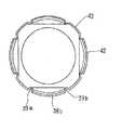
次に、本発明の第1実施形態について、図1〜6を参照して説明する。
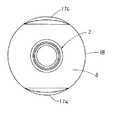
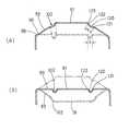
本実施形態は、丸形ボトルに係わるもので、図1,2に示すように、ボトル1は、口筒部2と胴部3と底部4とからなり、PET、高密度ポリエチレンその他可撓性のある硬質の合成樹脂を素材樹脂としてブロー成形によって成型されている。
前記口筒部2には、キャップを被嵌するためのネジ5と該ネジ5の下端に形成された膨出部6が設けられ、その下方には保持環7が設けられている。
【0013】
胴部3は、口筒部2に続く球帯状の肩壁8と、該肩壁8に続く円筒状の胴壁9および該胴壁9に続き底部4に続く球帯状の下部周壁10とからなり、肩壁8と胴壁9上端との間には、胴壁9外周より一定距離内側に位置する互いに直角をなす四つの垂直面上で半円形に延びる可変リブ11a,b,c,dが配設されており、それぞれの可変リブ11は、その上端部12が肩壁8内に位置し、両側に延びた下端部13は、胴壁9と肩壁8との境界部に達している。
【0014】
前記下部周壁10は、胴壁9下端より延び、底部4の底壁14の周縁15に続いており、球帯の形状は肩壁8と同径で対称的になっている。
下部周壁10には、前記可変リブ11と同一垂直面上で、可変リブに対して上下方向に対称形となる4つの可変リブ16a,b,c,dが設けられている。
上下の可変リブ11,16に囲まれた胴部3の壁面は、変形復元可能な可変面17a,b,c,dを形成し、胴部のその他の壁面は不変面18となっている。
【0015】
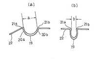
可変リブ11は、胴部の補強とともに、胴部壁の折れ部を形成するものである。 その断面形状は、図3に示すように、やや肉厚の中央部19とやや薄肉の側部20a,bを有しており、その両縁部は胴部壁と連結されている。
それぞれの連結部21a,21bは、丸みが形成されており、連結部においては、側部20a,bの肉厚は連結された胴部壁22の肉厚とほぼ等しくなっている。
中央部19と側部20a,bとは弧状に湾曲しているので、胴壁部が折り曲げられたり、胴部巾を縮小するなど両連結部21a,21bを双方から押圧するような力が加わると、まず、側部が湾曲し、続いて中央部も湾曲されるので、可変リブ全体が弧状に湾曲して連結部間の間隔aが間隔bに狭められる。
また、逆に両連結部の間隔を広げるような力が加えられると、湾曲度が変わり、間隔は広がる。
【0016】
可変リブの中央部19、側部20a,bの湾曲およびリブ両端部と胴部壁22との連結部21の変形は、弾性変形の範囲で行われるようになっている。
弾性変形の範囲は、素材樹脂の弾性限応力、可変リブと連結部の形状、厚さ等によって設計的に定められ、本発明においては、素材樹脂としてPET、高密度PE、PPなど可撓性のある硬質の樹脂を用い、可変リブの形状、内厚、壁厚、連結部の曲率などを実験をくり返すことによって設定している。
【0017】
次に、ボトルの変形、減容について、図4,5,6を参照して説明する。
上記ボトル1は、可変面17a,b,c,dを押圧すると、上下の円弧状の可変リブ11,16の内側の連結部を含む平面Xに対して、可変面17が該平面Xを越え、スナップ動作によって反転位置に維持されるので、可変面17の膨出した胴壁9は内方に湾曲して平面内に陥没し、ボトル胴部は、四つの平面によって形成される角形ボトルと同じ形状になって、その分減容されることになる。
【0018】
そのときの変形状態を図5を参照して、くわしく説明する。
図5は、可変リブ11の上端部12とボトル軸線を含む面で切った肩壁8上部の縦断面図であり、可変リブの反転作用を模式的に描いた図である。
図5(a)において、胴部3の可変面17を押圧していくと、可変リブ11の両連結部21a,21bは、ほぼ等しいモーメントを受けて曲がることになるから、両連結部21a,21bにおいては、側部20と肩壁8のなす角はほぼ等しく変形する。
胴部の可変面17が押圧されて平面Xを越えるときには、図5(b)に示すように可変面17の壁面が曲線から直線になるとすると、連結部21bの位置は、変形前の位置から距離s上方に移動し、可変リブ11の両連結部間の間隔が短くなり、間隔aから間隔bに変化して可変リブ11が湾曲される。
【0019】
次いで、胴部の可変面17をさらに内方に押圧すると、図5(c)に示すように可変面17の膨出面は内方に湾曲した陥没面となり、その縦断面は、変形前の曲線に対称的な曲線となる。
連結部21a,bにおいて、可変リブ11の側部20aと肩壁上方部8a、側部20bと肩壁8のなす角は、ほぼ等しくなるので、両連結部21a,21bは、上部の連結部21aを通る垂直線上に位置するようになり、可変面17は、平面Xより内方に位置するようになる。
同時に可変リブの両側部を圧迫する力は小さくなるので、両連結部間の間隔cは間隔bより広がり、湾曲度は減少する。
胴部の可変面17を平面Xより膨出した状態に復元させるためには、可変リブの両連続部間の間隔を再び縮小させ、変形させる復元力が必要となる。
【0020】
下部に配設された可変リブ16は、上部の可変リブ11と対称的に形成され、球帯状の下部周壁10内に位置しているので、可変リブ11について述べた上記作用がもたらされ、変形状態も対称的になるので、ボトル1の可変面17全体は、図4に示すように、スナップ動作により反転変形され、反転状態は、復元力を作用させない限りそのまま維持される。
復元は、ボトル内部に圧縮空気を吹き込むことによって行われ、それまでは反転状態が維持されるのである。
【0021】
次に、減容率について図6を参照して説明すると、本発明にいう減容率は、成形ボトルの占める四角柱容積に対し、変形した減容ボトルの占める四角柱容積を差し引いた容積の割合である。
ボトルの高さが同一の場合には、ボトルの占める四辺形の面積となる。
図6において、円形成形ボトルの占める面積は直径D×直径Dに対して、対向する変形面(平面X)までの距離をA,Bとすると、変形した減容ボトルの占める面積は、A×Bとなり、
減容率は、(D・D−A・B)/D・D
で表される。
本実施形態においては、それぞれの可変リブは、同一距離内方に配設されているから、A=Bとなっている。
【0022】
減容率は、可変リブの配設場所を変えることによって、換言すればA,Bの値を変えることによって変更することができる。
可変面、可変リブの変形を小さくすれば弾性変形の範囲に押さえられるが、わずかな外力を加えても復元することになり、可変リブの変形は、可変面がスナップ動作で反転、復元可能であるようにしなければならない。
【0023】
積載効率は、直交する二軸方向にボトルを相互に接合するよう整列させたときに、単位面積当たりに積み込まれる成形ボトルの個数に対する減容ボトルの個数の比であり、D・D/A・Bで表される。
減容ボトルを箱詰めにすると積載効率を高めることができる。
【0024】
本実施形態では、図示した減容ボトルは、減容率は約32%となっており、積載効率は、1.46となり、ボトルの積載量を46%上昇させることができる。
【0025】
本実施形態では、可変リブを弧状として上下に配置したことを一つの特徴として4面に配設しているが、必要に応じ配設位置、数は変更することができる。
次に変形実施例について図7を参照して説明する。
上記で説明したものと異なる点は、可変リブ11,16をボトルの軸心に対向するように配設し、可変面を対向する二面17a,17cとしたことである。
ボトルの減容率は、(D・D−A・D)/D・Dとなり、図示した実施例では約17%となっている。
また、可変リブを上下一対だけとし、可変面を一面だけにしてもよく、この場合、ボトルの減容率は約9%となる。
【0026】
また、可変リブの位置をボトルの中心に寄せることによって、減容率を高めることができる。
減容ボトルを成形ボトルの円周に内接する正四角形に近づけることによって減容率を50%に接近させることができるが、可変リブの位置をボトルの中心に寄せると、可変リブの上端が位置する肩壁の肉厚が厚くなり、可変リブの上端における変形が困難となり、また、胴壁に位置する可変面の側縁部が相互に干渉し合うという問題も発生し、一定の限度がでてくる。
そこで、可変リブの位置を変え実験を重ねたところ、可変面が干渉しないだけの細巾の壁面を残して、隣り合う可変リブの下端部側縁をほぼ一致するように接近させて配設することによって、ボトルの減容率を45%まで上げることができた。
【0027】
可変リブの配設位置は、縦方向と横方向で異なるようにしてもよく、ボトルの形状は楕円ボトルであってもよい。
【0028】
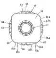
次に、縦長の円形ボトルに係わる第2実施形態について、図8〜12を参照して説明する。
前記第1実施形態では上下に対向して位置する半円状の可変リブを配設したが、ボトルが縦長になると、上下の可変リブの作用だけでは胴壁の不変面に外力がかかると可変面の胴壁中央に復元力が働き、復元が全長に渡って広がり反転状態を維持することが困難になるという問題が生じる。
本実施形態はこれを改善するため、可変リブを胴壁にも配設して胴長の円形ボトルにも適応させるようにしたもので、以下前記実施形態と異なる点を中心に説明する。
【0029】
図8〜10に示すようにボトル30は、口筒部31、胴部32、底部33とからなり、胴部32は、球帯状の肩壁34と円筒状の胴壁35と、前記肩壁34と対称形になっている球帯状の下部周壁36とからなっている。
肩壁34から下部周壁36にかけて、胴壁35から所定距離内側に位置する互いに直角をなす四面の垂直面上にそれぞれ可変リブ37a,b,c,dが配設されている。
【0030】
可変リブ37は、円弧リブ38、縦リブ39、横リブ40とからなっている。円弧リブ38は、肩壁34内に位置する半円形の上部の円弧リブ38aと、該円弧リブ38aに対称形とし、下部周壁36内に位置する下部の円弧リブ38bとを具えており、胴壁35内に位置して円弧リブ38a,bの半円の両端縁を結んで、二つの直線状の縦リブ39a,bが設けられている。
上下の円弧リブ38a,bには、その両端縁を結ぶ円弧状の横リブ40a,bが架設されており、その円弧中央部41a,bは、胴壁35の上下の端部、すなわち胴壁35と肩壁34、胴壁35と下部周壁36の境界上に位置している。
前記可変リブ37によって囲まれた部分は、胴部32の膨出された可変面42a,b,c,dとなっており、その他の胴部32の部分は、不変面43となっている。
【0031】
次に、可変リブ37の作用について、図11,12を参照して説明する。
可変リブ37の断面形状は、第1実施形態のそれとほぼ同一であって、図11に示すように、肉厚の中央部44とやや薄肉の側部45が円弧状に湾曲して形成されており、両側部45の端縁は、胴部32の対応する壁面に続いており、丸みを持った連結部46となっている。
上下の円弧リブ38a,bは、肩壁34または下部周壁36内に配設され、前記第1実施形態における可変リブ11,16と同様の作用効果をもたらすことができる。
【0032】
胴壁35に配設された左右の縦リブ39a,bは、図11に示すように、胴壁35の可変面42を押圧するとき、まず、縦リブ39a,bの両方の連結部46の間隔がaからbに縮小し、可変面42の胴壁35を平面状とし、さらに、内方に押圧すると、胴壁35はスナップ動作によって反転し、内方に湾曲する。
その際、縦リブ39a,bは、連結部46間の間隔を拡大して可変面を反転位置を維持するように作用する。
そして、縦リブ39は、胴壁35の上下全長に渡っているので、胴壁35の不変面43に外力がかかっても復元することなく、可変面42の反転状態が確実に維持されるのである。
【0033】
次に、弧状の横リブ40a,bの作用について説明すると、横リブ40a,bは、その円弧中央部41a,bが、胴壁35の端部すなわち胴壁35と肩壁34との境界線または胴壁35と下部周壁36との境界線に位置していることによって、可変面42上下の球帯の反転を容易にするとともに、反転状態を確実に維持するように作用するものである。
【0034】
本実施形態では、図12に示すように、円弧リブ38a,b、縦リブ39a,b、横リブ40a,bの作用が総合され、可変面42を押圧していくと、不変面43と可変リブ37の接続部によって形成される平面Xaに対して、可変面42がスナップ動作によって反転し、膨出した可変面42が内方に湾曲陥没して減容されることになる。
その減容率は、図示した実施例では、約32%である。
【0035】
本実施形態では、可変面を四個所に設けているが、可変面は一個所または二個所に配設するだけでもよく、また、可変リブの配設位置を内方に位置させること等によって前記第1実施形態と同様に減容率を変えることができる。
【0036】
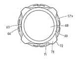
次に、円形ボトルに係わる第3実施形態について図13〜18を参照して説明する。
本実施形態は、第1実施形態と同様に円形ボトルに係わるものであるが、胴部周面に円筒形膨出部を設けた角形壁を形成し、膨出部を可変面として可変リブを配設したものである。
【0037】
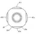
図13〜15に示すように、ボトル50は、前記各実施形態と同じく口筒部51と胴部52および底部53とからなっており、胴部52は、口筒部51に続くほぼ球帯状の肩壁54と、胴壁55とを具えている。
胴壁55は、前記肩壁54に続く角壁56と、該角壁56から膨出するよう形成され、上下を球帯壁57a,57bとし、中間部を円筒壁58とした膨出部59とを具えている。
角壁56の角部は裁断されて、肩壁54に続く所定の巾の円筒壁60が形成され、胴部52は、実質的には円形に近い形状になっている。
【0038】
胴壁55は、図15に示されているように、一定巾の円筒壁60と、該円筒壁60に続く角壁56の細巾の平壁側部56aと、円筒壁60より小径の円筒壁58によって形成されており、平壁側部56aと膨出部59の円筒壁58との連続部は、直線縁61a,61bとなっている。
前記膨出部59の上部球帯壁57aは、角壁56の平壁上部56bに連続しており、その連続部は円弧縁62aとなっている。
下部球帯壁57bは、角壁56の平壁下部56cに連続しており、その連続部は円弧縁62bとなっている。
直線縁61a,61b、円弧縁62a,62bによって長円状の垂直な平面が形成されている。
【0039】
前記膨出部59の中央には、上部球帯壁57a、円筒壁58、下部球帯壁57bにわたって上下に縦リブ63が配設されており、上下の球帯壁57a,bのそれぞれには、前記縦リブ63に交差する所定長さの横リブ64が配設されている。
縦リブ63及び横リブ64は、いずれも可変リブであって、図15に示されているように、肉厚の中央部65とやや薄肉の側部66a,bとを有しており、両縁部は、膨出部59の壁面に接続され、連結部67a,bを形成している。
【0040】
前記底部53は、図16に示すように、円形の底壁68と該底壁68から立ち上がる周縁69、および該周縁69と角壁56の下端部70とを結ぶ傾斜壁71、円筒壁60の下端部72とを結ぶ傾斜壁73とからなっている。
【0041】
次に、可変リブの作用とボトルの変形作用について説明する。
膨出部59を押圧すると、膨出部59は、直線縁61a,bの上下の円弧縁に沿ってスナップ動作によって反転し、内方に湾曲し、陥没する。
【0042】
そのときの縦リブ63の作用について、図17を参照して説明すると、膨出部59を押圧すると、膨出部59の円筒壁58は内方に移動するが、円筒壁60と平壁側部56aが屈曲されているので、円筒壁58は、円筒壁60の側端縁74と直線縁61a,bを軸として変形し、円筒壁58の断面は曲線からほぼ直線になり、図17(b)に示すように、縦リブ63を湾曲させて、両連結部67a,b間の間隔aを間隔bに縮小するように作用する。
さらに押圧すると、円筒壁58は内方に湾曲して、縦リブ63は元の状態に戻り、反転状態を維持する。
【0043】
球帯壁57a,bにおいては、膨出部59はボトルの横方向と同時に縦方向に湾曲することになるが、縦リブ63の上記の作用によって、横断面での球帯壁57a,bの横方向への変形を行い、横リブ64が変形することによって第1実施形態における可変リブと同様に、球帯壁57a,bの縦断面での縦方向への湾曲変形をさせるように作用する。
両者の作用によって、球帯壁57a,bを反転させ、反転状態を維持するように作用するが、同時に横リブ64と縦リブ63が交差しているので、横リブの変形によって球帯壁57の変形面に剛直性を付与し、縦リブ63の復元を阻止するように作用する。
【0044】
膨出部59が、反転して内方に湾曲することによって変形されたボトルは、角壁56の形状に減容されるが、図示した実施例では減容率は約32%である。
本実施形態においても、縦長のボトルでは第2実施形態と同様に直線縁61a,61bに沿って縦リブを配設してもよい。
また、膨出部を角壁の対向する二面に配設するだけでもよく、角壁の形状を短形としてもよい。
【0045】
次に、角形ボトルに係わる第4実施形態について、図19〜30を参照して説明する。
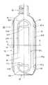
図19〜22に示すように本実施形態のボトル80は、口筒部81と胴部82、底部83とからなり、PETその他可撓性を有する硬質の樹脂を素材樹脂とし押出しブロー成形によって成形されている。
前記口筒部81には、キャップを被嵌するためのネジ84と該ネジ84の下端に形成された膨出部85が設けられ、その下方には保持環86が設けられている。
【0046】
前記胴部82は、口筒部81に連続して形成される肩壁87と該肩壁87に連続する多角周壁88からなり、前記底部83は、長方形の底壁89とその周縁から立ち上がる底周壁90とを具えている。
多角周壁88は、前後に対向して平行に配設された長方形の平壁91a,bと、肩壁87に連続し、左右の側部に対向して平行に配設された等脚台形の側壁92a,b、および平壁91と側壁92との間に配設されたほぼ台形の側部傾斜壁93a,b,c,dとを具えている。
【0047】
前記肩壁87の側縁94と平壁91および側部傾斜壁93との間には、上部傾斜壁95a,bが配設されており、底周壁90の前後の端縁96と平壁91a,b、および側部傾斜壁93との間には下部傾斜壁97a,bが配設されている。
前記側壁92は、前後の端部は丸みをもって屈曲し、ボトル前後面で上下に延びる帯壁98が形成され、その側縁99は、側部傾斜壁93の縁部に連続している。
【0048】
平壁91a,bの側端縁100と各側部傾斜壁93a,b,c,dの側端縁101との間には、両者を接続する縦リブ102が配設され、平壁91a,bの上端縁103と上部傾斜壁95の下端縁104との間には、両者を接続する上部横リブ105が配設され、平壁91a,bの下端縁106と下部傾斜壁97a,bの上端縁107との間には、両者を接続する下部横リブ108が配設されている。
上部傾斜壁95の側端縁109と側部傾斜壁93の上端縁110および平壁91の角部円弧縁111との間には上部三角リブ112が配設され、下部傾斜壁97の側端縁113と側部傾斜壁93の下端縁114、および平壁91の角部円弧縁111との間には、下部三角リブ115が配設されている。
【0049】
前記縦リブ102、各横リブ105,108および各三角リブ112,115は、いずれも弾性限度内で変形、復元可能な可変リブであって、それらの可変リブで接続された平壁91、側部傾斜壁93、上部傾斜壁95、下部傾斜壁97によって可変面が形成され、肩壁87、側壁92および底壁89によって形成される不変面に対して、変形、復元可能となっている。
変形は、平壁91a,bを押圧することによって行われ、スナップ動作によって可変面がボトル内部に偏寄され、押圧を解いてもその状態が維持される。
【0050】
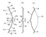
次に、各可変リブの構造とその作用について、図23〜29を参照して説明する。
まず、始めに各可変リブの求められる作用効果の基本について、図23を参照して説明する。
説明の前提として、上部傾斜壁95が、その壁面と両側の二つの帯壁98の側縁99との交点を相互に結ぶ直線116を軸として廻動するものとし、各傾斜壁は等脚台形で、その巾および傾斜辺の傾斜角度はすべて同一であり、縦リブ102、上部横リブ105、下部横リブ108の断面形状とその巾も、すべて同一であると仮定して説明する。
【0051】
側部傾斜壁93は側縁99を軸とし、下部傾斜壁97は端縁96を軸として廻動するが、各軸線によって、長方形の平面Yが形成され、平壁91は、平面Yに平行に配設されることになる。
平面Yのすべての角部は相互に対称形になっているので、一つの角部のみを図示して以下説明する。
【0052】
各傾斜壁(93a,b、95、97)の傾斜角度をαとし、平壁91を平面Yに平行に移動させ、各傾斜壁を廻動させ平面Yに一致させると、平壁91は91Aに、側部傾斜壁93は93Aとなる。
そして、側端縁101は線101A上に、上端縁110は線110A上に位置するようになり、同じく上部傾斜壁95の下端縁104は線104A上に、側端縁109は線109A上に位置することになる。
【0053】
前記可変面のスナップ動作による反転は、可変面がまず平面Yと一致し、ついで、平面Yを越えて内側に位置させることであるが、そのときの各可変リブの必要とする作用効果について述べる。
まず、縦リブ102、上部横リブ105については、図に示すように可変リブの間隔aを間隔bとなるように縮小させることである。
つぎに、上部三角リブ112については、側端縁109、上端縁110、線109A、線110Aの交点をO、それぞれの端点をA、B、A1 、B1 とすると、∠AOBを∠A1 OB1 に縮小させ、平面上で平壁の角部円弧縁111と線分ABとの距離を角部円弧縁111と線分A1 B1 との距離になるように縮小させることである。
これは、三角リブを、長手方向と同時に横方向に湾曲変形させることによって達成できる。
【0054】
次に、縦リブ102とボトル80の横断面での変形について、図24を参照して説明する。
図24(a)に示すように、縦リブ102は、中央部をやや肉厚とし、断面円弧のリブ本体120を有しており、その一方の端部121は、側部傾斜壁93の側端縁101と接続しており、他方の端部122は、平壁91の側端縁100より傾斜して突出する突出縁123と接続されている。
【0055】
平壁91を押圧していくと、平壁91は、ボトルの中心に向かって平行に移動し、側部傾斜壁93は、帯壁98の側縁99を軸として廻動する。
平壁91と側部傾斜壁93とが平面となると、図24(b)に示すように、縦リブ102の両端121,122間の間隔がaからbに狭くなり、リブ本体120は大きく湾曲させられる。
【0056】
次いで、さらに押圧すると、平壁91は、引き続いて内方に移動し、側部傾斜壁93が内方に廻動するので、縦リブの両端の間の間隔は広がり、ほぼもとの状態を回復する。
したがって、平壁91と側部傾斜壁93は、スナップ動作によって反転され、平壁91の外方に移動させるための力を付与しない限り、反転状態が維持されることになる。
【0057】
次に、上部横リブ105、下部横リブ108とボトル80の縦断面での変形について、図25を参照して説明する。
図25(a)に示すように、上部横リブ105と、下部横リブ108とはほぼ同形であって、前記した縦リブ102と同様に中央がやや肉厚のリブ本体125a,bと端部126a,b、端部127a,bを有している。
上部横リブ105の端部126aは、上部傾斜壁95の下端縁104と接続され、端部127aは、平壁91の上端縁103より傾斜して突出する突出縁128aと接続されている。
下部横リブ108の端部126bは、下部傾斜壁97の上端縁107と接続されており、端部127aは、平壁91の下端縁106より傾斜して突出する突出縁128bと接続されている。
【0058】
平壁91を押圧していくと、上部傾斜壁95は、前記した直線116を軸として廻動し、下部傾斜壁97は、底周壁90の端縁96を軸として廻動する。
図25(b)に示すように、平壁91と、上部および下部傾斜壁95,97が平面となるとき、端部126a,bと端部127a,bの間の間隔は狭くなり、リブ本体125は大きく湾曲され、前記した縦リブの作用と同様の作用がもたらされることになる。
【0059】
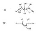
次に、三角リブの構成とその作用効果について、図26〜28を参照して説明する。
各三角リブ112,115は、平壁91の各角部に形成された角部円弧縁111と、角部に対応する上下部の傾斜壁の側端縁と、該側縁端に対向する側部傾斜壁の上下いずれかの端縁との間に形成されている。
図26に示すように、上部三角リブ112は、平壁91の角部円弧縁111からリブの長手方向に突出するよう形成された膨出壁130と、対向する側端縁109、上端縁110との間を連結するリブ底壁131とからなっている。
【0060】
膨出壁130は、角部円弧縁111の上端からリブの長手方向に下方に湾曲した曲線を稜線132とし、その裾線133を、平壁91の突出縁123を含む垂直面と突出縁128を含む垂直面上に位置するようにしている。
リブ底壁131は、傾斜壁(93,95)の側端縁109、上端縁110によって囲まれた舟底形の底壁主部135と、膨出壁130とによって分岐された二つの分岐部136,137とからなっている。
【0061】
底壁主部135の断面は、図27に示すように、弧状に湾曲した壁面となっており、中央部138が側部139よりやや厚肉で、接続する傾斜壁の端縁(109,110)との連結部140において、曲がり易くなっており、両連結部140の間隔が変化するときには、全体として湾曲変形するようになっている。
分岐部136,137の断面は、底壁主部135の断面とほぼ同じ形状となっている。
【0062】
底壁主部135の中央の谷線141は、前記膨出壁130の稜線132に続いており、底壁主部135から分岐部136,137にかけては、一つの広巾の弧状の壁面から二つの細巾の弧状の壁面に滑らかに連続して分岐している。
分岐部においては、膨出壁130の側壁と対向する傾斜壁の端縁(109,110)との間に壁面が形成され、縦リブ102、上部横リブ105の壁面に連続している。
【0063】
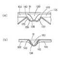
次に、上記構成による三角リブの作用効果について、図27,28を参照して説明する。
平壁91を押圧すると、平壁91はボトル80の内側に向かって平行に移動し、各傾斜壁(93,95)は廻動する。
その際、先に図23について説明したように、各傾斜壁の端縁のなす角度が小さくなり、リブ底壁131の両側の連結部の間隔は縮小する。
【0064】
平壁91と各傾斜壁(93,95)が平面Y上に一致したときには、底壁主部135においては、図27(b)に示すように、両連結部140間の間隔が縮小し、リブ底壁131の壁面は湾曲変形する。
さらに平壁91を押圧すると、リブ底壁131は、平面Yを越えて反転し、両連結部140間の間隔を広げ、リブ底壁131を元の状態に戻す。
【0065】
底壁主部135と分岐部136,137の合流点付近においては、図28,29に示すように、両連結部140の間の間隔が狭められると同時に、膨出壁130中央部の押圧によって、各分岐部の二つの湾曲面が一つの湾曲面となり、底壁主部135の湾曲面に連続することになる。
各分岐部136,137においては、膨出壁130の側面と傾斜壁の端縁の間の間隔が狭くなり、傾斜壁の端縁(109,110)と膨出壁周面との間で湾曲変形された湾曲面が形成され、縦リブ、横リブの変形したリブ面に滑らかに続くことになる。
【0066】
リブ底壁131の変形は、各傾斜壁の側端縁109、上端縁110のなす角度の縮小と膨出壁130の押圧力によって行われるが、同時に、縦リブ102、上部横リブ105の変形、湾曲が行われ、その変形は、リブ底壁131の分岐部136,137に伝達されるが、分岐部136,137によって、底壁主部135の変形と結合され、三角リブの作用と総合されるのである。
【0067】
以上のように、縦リブ102、各横リブ105,108、各三角リブ112,115作用が総合されて、図30に示すように、可変面を平面Yに対してスナップ動作により反転し、その反転状態が維持され、減容ボトルとなるのである。
減容ボトルの復元は、前記各実施形態のボトルと同様に、ボトル内に空気を吹き込むことによって行われるが、他に平壁を引き出す適当な手段がないから、反転状態の維持は、より確実となっている。
本実施形態においては、図示の実施形では減容率は、約33%になっているが、底壁の巾に対して傾斜壁の傾斜角度を変え、対向する平壁の距離を変えることによって、減容率を変えることができる。
【0068】
上記第4実施形態の角形ボトルは、押し潰し容器としても使用できる。
ボトルの容積は、実質的に減容され空気を吹き込み内部から復元力を付与しない限り復元しないので、ボトル廃棄のために押し潰し容器として利用可能である。
内容物の注出後、使用済みのボトルを押圧すると簡単に押し潰すことができ、そのまま廃棄することによってゴミ容量を減らすことができる。
【0069】
【発明の効果】
本発明は、上記のように構成されているから、次の効果を奏する。
ボトルの胴部壁面に、折れ部を形成する可変リブを配設して可変面を形成し、可変リブを弾性限度内で変形させ、前記可変面を形状不変面に対してスナップ動作により反転させ、反転状態を維持するようにしているから、ボトルを弾性変形の範囲内で変形させ減容することができる。
変形した減容ボトルを箱詰め輸送する時には、積載効率を高めることができる。
減容ボトルは、弾性変形の範囲内でのスナップ動作による変形であるから、スナップ動作により反転復元させることができる。
復元は、ボトル内に圧縮空気を吹き込むだけで容易に行うことができ、弾性変形の範囲内の変形で塑性変形はしないから商品価値を損なうことはない。
【図面の簡単な説明】
【図1】 本発明の第1実施形態におけるボトルの一部断面正面図である。
【図2】 ボトルの平面図である。
【図3】 可変リブの横断面図で、(a)は変形前、(b)は変形時の状態を示す説明図である。
【図4】 変形減容時の状態を示すボトルの一部断面正面図である。
【図5】 可変リブの作用を説明する肩壁の縦断面図で、(a)は変形前、(b)は押圧時、(c)は反転時の状態を示す説明図である。
【図6】 変形減容時の状態を示すボトルの平面図である。
【図7】 一つの実施例を説明するボトルの平面図である。
【図8】 本発明の第2実施形態におけるボトルの一部断面正面図である。
【図9】 ボトルの平面図である。
【図10】 図8のA−A線における断面平面図である。
【図11】 可変リブの作用を説明する胴壁の横断面図である。
【図12】 変形減容時の状態を示すボトルの一部断面正面図である。
【図13】 本発明の第3実施形態におけるボトルの一部断面正面図である。
【図14】 ボトルの平面図である。
【図15】 図13のA−A線における断面平面図である。
【図16】 ボトルの底面図である。
【図17】 可変リブの作用を説明する肩壁の横断面図で、(a)は変形前、(b)は押圧時、(c)は反転時の状態を示す説明図である。
【図18】 変形減容時の状態を示すボトルの一部断面正面図である。
【図19】 本発明の第4実施形態におけるボトルの正面図である。
【図20】 ボトルの一部断面側面図である。
【図21】 ボトルの平面図である。
【図22】 図19のA−A線における断面平面図である。
【図23】 可変リブの作用を説明する図である。
【図24】 縦リブの作用を説明するボトルの一部横断面図で、(a)は変形前、(b)は変形時の状態を示す図である。
【図25】 横リブの作用を説明するボトルの一部縦断面図で、(a)は変形前、(b)は変形時の状態を示す図である。
【図26】 三角リブの構成を説明する図で、(a)は平面図、(b)は図(a)をX方向からみた側面図、(c)はY方向からみた側面図である。
【図27】 三角リブ底壁主部の断面形状の作用を説明する断面図で、(a)は変形前、(b)は変形時の状態を示す図である。
【図28】 三角リブ底壁主部と分岐部との合流点付近の断面形状の作用を説明する断面図で、(a)は変形前、(b)は変形時の状態を示す図である。
【図29】 三角リブの作用を説明する縦断面図で、(a)は変形前、(b)は変形時の状態を示す図である。
【図30】 変形減容時の状態を示すボトルの一部断面側面図である。
【符号の説明】
1,30,50,80 ボトル
2,31,51,81 口筒部
3,32,52,82 胴部
4,33,53,83 底部
8,34,54,87 肩壁
9,35,55 胴壁
10,36 下部周壁
11a,b,c,d 可変リブ
16a,b,c,d 可変リブ
17a,b,c,d 可変面
18 不変面
19 中央部
20a,b 側部
21a,b 連結部
22 胴壁部
37a,b,c,d 可変リブ
38a,b 円弧リブ
39a,b 縦リブ
40a,b 横リブ
42a,b,c,d 可変面
43 不変面
56 角壁
57a,b 球帯壁
58 円筒壁
59 膨出部
63 縦リブ
64 横リブ
91a,b 平壁
92a,b 側壁
93a,b,c,d 側部傾斜壁
95a,b 上部傾斜壁
97a,b 下部傾斜壁
102a,b 縦リブ
105 上部横リブ
108 下部横リブ
112 上部三角リブ
115 下部三角リブ
120 リブ本体
121,122 端部
123 突出縁
130 膨出壁
131 リブ底壁[0001]
BACKGROUND OF THE INVENTION
The present invention relates to a container that can be deformed and restored, and more particularly, to a plastic bottle that can be deformed and restored within an elastic limit and can be transported with a reduced volume.
[0002]
[Problems to be solved by the invention]
When using blow-molded bottles, manufacturers of beverages, various household items, etc., purchase bottles from container manufacturers, fill the bottles with the contents at the filling factory, package them, and ship them as products. is doing.
Therefore, the container maker packs the blow-molded bottles at the molding factory and transports them to the content filling factory.
[0003]
The “Blow Fill Sealing Method” is also known, which fills the contents following the blow molding of the bottle, but the container manufacturing and content manufacturing are specialized, and the content manufacturer must mold the bottle. In general, bottles blow-molded at a molding plant are often transported to a content filling plant.
[0004]
However, the transportation of empty bottles from the molding factory to the filling factory is light in weight, but the volume is bulky, and the number of parts transported at one time is small, and the transportation efficiency is extremely low.
Further, when the bottles are circular, the bottles are aligned and boxed so as to be joined to each other in two orthogonal directions, so that the space volume between the bottles is increased and the loading efficiency is further reduced.
[0005]
In view of the above circumstances, the present invention has a technical problem of temporarily reducing the volume of the bottle to increase the loading and transport efficiency, and the molded bottle is reversely deformed and restored within the limit of elastic deformation of the material resin. The object is to provide a plastic bottle that is made possible.
[0006]
[Means for Solving the Problems]
The above technical problem is that a variable part that bulges from a predetermined plane and can be deformed and restored within a range of elastic deformation is formed on the wall surface of the bottle body, and other parts are made shape-invariant parts, and the variable surface snaps. Can be achieved by inverting the bottle from the predetermined plane to the inside of the bottle and maintaining the inverted deformation state.
[0007]
In order to achieve the technical problem, the present invention, as a plastic bottle,A fold portion is formed on the wall surface of the body of the bottle, a variable rib that is elastically deformed is provided to form a variable surface, and the variable surface is on a shape invariable surface side with respect to a plane formed by the variable rib. In plastic bottles that are inverted by snapping and maintained in an inverted state, the cross section of the variable rib consists of a thick central part and thin side parts, and the edge of the side part is connected to the body wall surface with roundness. The variable rib is curved and deformed within the elastic limit.
The volume reduction of the molded bottle is reduced to a volume reduction rate of 10% to 45%.
[0008]
According to the shape of the bottle, as a technical means in a round bottle, a round bottle having a body portion composed of a ball-shaped shoulder wall, a cylindrical body wall, and a ball-shaped lower peripheral wall, the ball-shaped shoulder wall And a semicircular shape at the position facing the top and bottom of the lower peripheral wallExtend toArrange variable ribs,The variable rib is a rib whose cross section is composed of a thick central portion and both thin side portions, the side edges of which are connected to the body wall surface with roundness, and are curved and deformed within the elastic limit. There,A configuration that allows a barrel wall that bulges from the plane to be a variable surface with respect to a plane formed by the variable rib, and allows the variable surface to be reversed, deformed and restored by a snap operation within an elastic limit. Is adopted.
[0009]
In addition, when the bottle is torso length, in a round bottle having a body composed of a ball-shaped shoulder wall, a cylindrical wall, and a ball-shaped lower peripheral wall, the ball-shaped shoulder wall and the lower peripheral wall A substantially semicircular arc-shaped variable rib is disposed at a position opposite to the upper and lower sides, and a variable vertical rib is provided in the cylindrical body wall to connect both end edges of the upper and lower arc-shaped variable ribs,The arc-shaped variable ribs and variable vertical ribs have a cross section consisting of a thick central portion and thin side portions, and side edges are connected to the body wall surface with roundness, and are curved and deformed within the elastic limit. A rib made ofThe arc-shaped variable rib and twoVariable vertical ribAdopting a configuration characterized in that the barrel peripheral wall bulging from the plane is made a variable surface, and the variable surface can be reversed and restored by a snap action within the elastic limit. Then, if necessary, variable lateral ribs that connect the variable vertical ribs are installed in the spherical belt-like shoulder wall and the lower peripheral wall, or in the cylindrical body wall.
[0010]
In a round bottle having a square wall, it is a round bottle provided with a body part having a mouth tube part and a square wall,SaidThe body part is formed so as to bulge from a spherical belt wall following the mouth tube part, a square wall following the shoulder wall, and the surface of the square wall, with the upper and lower parts being spherical belt walls, and the middle part being a cylindrical wall And a variable vertical rib is provided in the center of the bulge portion over the upper spherical wall, the cylindrical wall, and the lower spherical wall, and the variable vertical rib is formed on the upper and lower spherical wall. A variable lateral rib of a predetermined length intersecting withThe variable vertical rib and the variable horizontal rib have a cross section consisting of a thick central portion and thin side portions, and the side edges are connected to the bulging portion wall surface with roundness, and are curved and deformed within the elastic limit. A rib made ofA configuration is adopted in which the wall surface of the bulging portion can be reversed and restored by snapping with respect to the square wall surface.
[0011]
In the case of a square bottle, the bottle includes a mouth tube portion, a body portion formed of a shoulder wall and a polygon tube wall continuous to the mouth tube portion, and a rectangular bottom portion, and the polygon tube wall includes front and rear portions. Between the flat wall and the side wall of the isosceles trapezoidal side wall disposed parallel to the shoulder wall and facing the left and right sides in parallel. A substantially trapezoidal side inclined wall disposed; an upper inclined wall disposed between edges of the shoulder wall, the flat wall, and the side inclined wall; and a bottom wall, a flat wall, and a side inclined wall. A lower inclined wall disposed between each end edge of the flat wall and the side inclined wall.Variable vertical ribOn the connecting part between the flat wall and the upper inclined wall and the connecting part between the flat wall and the lower inclined wall.Variable lateral ribBetween the side edge of the upper inclined wall and the upper edge of the side inclined wall, and between the side edge of the lower inclined wall and the lower edge of the side inclined wall.Triangular variable ribThe variable surface formed by the flat wall and each inclined wall can be reversed and restored by snapping within the elastic limit with respect to the invariable surface formed by the shoulder wall, the side wall and the bottom wall. Adopting a configuration characterized byTriangular variable ribIt consists of a bulging wall that projects from the corner arc edge of the flat wall in the longitudinal direction of the rib and a rib bottom wall that connects between the opposite edges of the inclined wall. Part and two branch parts branched by the bulging wall, each branch part correspondingVariable vertical ribOrVariable lateral ribA configuration characterized by being continuous is adopted.
The restoration of the deformation volume reducing bottle is characterized in that it is restored by blowing compressed air from the mouth tube portion of the bottle.
[0012]
DETAILED DESCRIPTION OF THE INVENTION
Next, a first embodiment of the present invention will be described with reference to FIGS.
This embodiment relates to a round bottle. As shown in FIGS. 1 and 2, the bottle 1 includes a
The
[0013]
The
[0014]
The lower
The lower
The wall surface of the
[0015]
The
Each of the connecting
Since the
On the other hand, when a force is applied to increase the distance between the two connecting portions, the degree of curvature changes and the distance increases.
[0016]
The bending of the
The range of elastic deformation is determined in design by the elastic limit stress of the material resin, the shape and thickness of the variable rib and connecting portion, etc. In the present invention, the material resin is flexible such as PET, high-density PE, PP, etc. Using a hard resin, the shape of the variable rib, the inner thickness, the wall thickness, the curvature of the connecting portion, etc. are set by repeating the experiment.
[0017]
Next, deformation and volume reduction of the bottle will be described with reference to FIGS.
When the bottle 1 is pressed against the
[0018]
The deformation state at that time will be described in detail with reference to FIG.
FIG. 5 is a longitudinal sectional view of the upper portion of the
In FIG. 5A, when the
When the
[0019]
Next, when the
In the connecting
At the same time, since the force pressing both sides of the variable rib is reduced, the distance c between the two connecting parts is wider than the distance b, and the curvature is reduced.
In order to restore the
[0020]
The
The restoration is performed by blowing compressed air into the bottle, and the inverted state is maintained until then.
[0021]
Next, the volume reduction rate will be described with reference to FIG. 6. The volume reduction rate referred to in the present invention is a volume obtained by subtracting the square column volume occupied by the deformed volume reduction bottle from the square column volume occupied by the molded bottle. It is a ratio.
When the height of the bottle is the same, the area of the quadrangle occupied by the bottle is obtained.
In FIG. 6, the area occupied by the round molded bottle is A × B with respect to the diameter D × diameter D, and the area occupied by the deformed volume reduction bottle is A XB
Volume reduction rate is (D ・ D−A ・ B) / D ・ D
It is represented by
In the present embodiment, the respective variable ribs are disposed at the same distance inward, and therefore A = B.
[0022]
The volume reduction rate can be changed by changing the location of the variable rib, in other words, by changing the values of A and B.
If the deformation of the variable surface and variable rib is reduced, it can be held within the range of elastic deformation, but it can be restored even if a slight external force is applied. The deformation of the variable rib can be reversed and restored by snapping the variable surface. There must be.
[0023]
The loading efficiency is the ratio of the number of reduced volume bottles to the number of molded bottles loaded per unit area when the bottles are aligned so as to be joined to each other in two orthogonal directions, and D · D / A · Represented by B.
Loading efficiency can be increased by boxing the reduced volume bottles.
[0024]
In the present embodiment, the volume reduction bottle shown in the figure has a volume reduction rate of about 32%, the loading efficiency is 1.46, and the bottle loading can be increased by 46%.
[0025]
In the present embodiment, the variable ribs are arranged on four sides as one feature that the variable ribs are arranged in an arc shape, but the arrangement position and number can be changed as necessary.
Next, a modified embodiment will be described with reference to FIG.
The difference from what has been described above is that the
The volume reduction rate of the bottle is (D · D−A · D) / D · D, which is about 17% in the illustrated embodiment.
Further, only one pair of upper and lower variable ribs may be provided, and only one variable surface may be provided. In this case, the volume reduction rate of the bottle is about 9%.
[0026]
Further, the volume reduction rate can be increased by moving the position of the variable rib toward the center of the bottle.
The volume reduction rate can be brought close to 50% by bringing the volume reduction bottle closer to the regular square inscribed in the circumference of the molded bottle. However, when the variable rib is moved to the center of the bottle, the upper end of the variable rib is positioned. The wall thickness of the shoulder wall becomes thick, making it difficult to deform at the upper end of the variable rib, and the side edges of the variable surfaces located on the trunk wall interfere with each other. Come.
Therefore, when the position of the variable rib was changed and the experiment was repeated, a narrow wall surface that does not interfere with the variable surface was left, and the lower edges of the adjacent variable ribs were placed close to each other so as to substantially coincide with each other. As a result, the volume reduction rate of the bottle could be increased to 45%.
[0027]
The arrangement position of the variable rib may be different between the vertical direction and the horizontal direction, and the shape of the bottle may be an elliptical bottle.
[0028]
Next, a second embodiment relating to a vertically long circular bottle will be described with reference to FIGS.
In the first embodiment, the semicircular variable ribs that are opposed to each other in the vertical direction are disposed. However, when the bottle is vertically long, it is variable when an external force is applied to the invariable surface of the body wall only by the action of the upper and lower variable ribs. There arises a problem that a restoring force acts on the center of the body wall of the surface, and the restoration spreads over the entire length, making it difficult to maintain the inverted state.
In the present embodiment, in order to improve this, a variable rib is also provided on the body wall so as to be adapted to a circular bottle having a body length. The following description will focus on differences from the above embodiment.
[0029]
As shown in FIGS. 8 to 10, the
From the
[0030]
The
The upper and
The portions surrounded by the
[0031]
Next, the operation of the
The cross-sectional shape of the
The upper and lower
[0032]
As shown in FIG. 11, when the left and right
At that time, the
Since the
[0033]
Next, the operation of the arc-shaped
[0034]
In the present embodiment, as shown in FIG. 12, the action of the
The volume reduction rate is about 32% in the illustrated embodiment.
[0035]
In the present embodiment, the variable surfaces are provided at four locations, but the variable surfaces may be provided only at one location or at two locations, and the variable ribs may be disposed inward by placing the variable ribs inward. The volume reduction rate can be changed as in the first embodiment.
[0036]
Next, 3rd Embodiment concerning a circular bottle is described with reference to FIGS.
This embodiment relates to a circular bottle as in the first embodiment, but forms a square wall provided with a cylindrical bulge on the circumferential surface of the trunk, and a variable rib with the bulge as a variable surface. It is arranged.
[0037]
As shown in FIGS. 13 to 15, the
The
A corner portion of the
[0038]
As shown in FIG. 15, the
The upper
The lower
An oval vertical plane is formed by the
[0039]
In the center of the bulging
The
[0040]
As shown in FIG. 16, the bottom 53 includes a
[0041]
Next, the action of the variable rib and the bottle deformation action will be described.
When the bulging
[0042]
The action of the
When further pressed, the
[0043]
In the
The action of both acts to invert the
[0044]
The bottle deformed by the bulging
Also in the present embodiment, in the vertically long bottle, the vertical ribs may be disposed along the
Further, the bulging portion may be disposed only on the two opposing surfaces of the square wall, and the shape of the square wall may be short.
[0045]
Next, 4th Embodiment concerning a square bottle is described with reference to FIGS.
As shown in FIGS. 19 to 22, the
The
[0046]
The
The polygonal
[0047]
Upper
The
[0048]
Between the
An upper
[0049]
The
The deformation is performed by pressing the
[0050]
Next, the structure and operation of each variable rib will be described with reference to FIGS.
First, the basics of the operational effects required for each variable rib will be described with reference to FIG.
As a premise for explanation, it is assumed that the upper
[0051]
The side inclined
Since all the corners of the plane Y are symmetrical with each other, only one corner is illustrated and described below.
[0052]
When the inclination angle of each inclined wall (93a, b, 95, 97) is α, the
The
[0053]
The reversal by the snap action of the variable surface is that the variable surface first coincides with the plane Y and then is positioned inward beyond the plane Y. The function and effect required for each variable rib at that time will be described. .
First, with respect to the
Next, regarding the upper
This can be achieved by bending and deforming the triangular rib in the lateral direction simultaneously with the longitudinal direction.
[0054]
Next, the deformation in the cross section of the
As shown in FIG. 24A, the
[0055]
When the
When the
[0056]
Next, when the pressure is further pressed, the
Therefore, the
[0057]
Next, the deformation in the longitudinal section of the upper
As shown in FIG. 25 (a), the upper
The
An
[0058]
When the
As shown in FIG. 25 (b), when the
[0059]
Next, the configuration of the triangular rib and the function and effect thereof will be described with reference to FIGS.
Each
As shown in FIG. 26, the upper
[0060]
The bulging
The
[0061]
As shown in FIG. 27, the cross section of the bottom wall
The cross sections of the
[0062]
The
In the branch portion, a wall surface is formed between the side wall of the bulging
[0063]
Next, the effect of the triangular rib having the above configuration will be described with reference to FIGS.
When the
At this time, as described above with reference to FIG. 23, the angle formed by the edges of the inclined walls is reduced, and the interval between the connecting portions on both sides of the
[0064]
When the
When the
[0065]
In the vicinity of the confluence of the bottom wall
In each branch part 136,137, the space | interval between the side surface of the bulging
[0066]
The
[0067]
As described above, the functions of the
The restoration of the volume reduction bottle is performed by blowing air into the bottle as in the bottles of the above embodiments. However, since there is no other suitable means for drawing out the flat wall, it is more reliable to maintain the inverted state. It has become.
In this embodiment, the volume reduction rate is about 33% in the illustrated embodiment, but by changing the inclination angle of the inclined wall with respect to the width of the bottom wall and changing the distance between the opposing flat walls. The volume reduction rate can be changed.
[0068]
The square bottle of the fourth embodiment can also be used as a crushing container.
Since the volume of the bottle is substantially reduced and is not restored unless air is blown in and a restoring force is applied from the inside, it can be used as a crushing container for disposal of the bottle.
When the used bottle is pressed after the contents are poured out, it can be easily crushed, and the waste volume can be reduced by discarding the bottle as it is.
[0069]
【The invention's effect】
Since this invention is comprised as mentioned above, there exists the following effect.
A variable rib that forms a fold is provided on the wall surface of the body of the bottle to form a variable surface, the variable rib is deformed within the elastic limit, and the variable surface is reversed with respect to the shape invariable surface by a snap operation. Since the inverted state is maintained, the bottle can be deformed and reduced in volume within the range of elastic deformation.
When the deformed volume reduction bottle is transported in a box, the loading efficiency can be increased.
Since the volume reduction bottle is deformed by the snap operation within the range of elastic deformation, it can be reversed and restored by the snap operation.
Restoration can be easily performed simply by blowing compressed air into the bottle, and since the plastic deformation does not occur due to the deformation within the range of elastic deformation, the commercial value is not impaired.
[Brief description of the drawings]
FIG. 1 is a partial cross-sectional front view of a bottle according to a first embodiment of the present invention.
FIG. 2 is a plan view of the bottle.
FIGS. 3A and 3B are cross-sectional views of a variable rib, where FIG. 3A is an explanatory view before deformation, and FIG. 3B is an explanatory view showing a state at the time of deformation;
FIG. 4 is a partial cross-sectional front view of a bottle showing a state at the time of deformation and volume reduction.
FIG. 5 is a longitudinal sectional view of a shoulder wall for explaining the action of a variable rib, where (a) is a state before deformation, (b) is during pressing, and (c) is a state during reversal.
FIG. 6 is a plan view of the bottle showing a state at the time of deformation and volume reduction.
FIG. 7 is a plan view of a bottle for explaining one embodiment.
FIG. 8 is a partial cross-sectional front view of a bottle according to a second embodiment of the present invention.
FIG. 9 is a plan view of the bottle.
10 is a cross-sectional plan view taken along line AA in FIG.
FIG. 11 is a cross-sectional view of the body wall for explaining the action of the variable rib.
FIG. 12 is a partial cross-sectional front view of a bottle showing a state during deformation volume reduction.
FIG. 13 is a partial cross-sectional front view of a bottle according to a third embodiment of the present invention.
FIG. 14 is a plan view of the bottle.
15 is a cross-sectional plan view taken along line AA in FIG.
FIG. 16 is a bottom view of the bottle.
FIGS. 17A and 17B are cross-sectional views of the shoulder wall for explaining the action of the variable ribs. FIG. 17A is an explanatory view showing a state before deformation, FIG.
FIG. 18 is a partial cross-sectional front view of a bottle showing a state during deformation volume reduction.
FIG. 19 is a front view of a bottle according to a fourth embodiment of the present invention.
FIG. 20 is a partial cross-sectional side view of a bottle.
FIG. 21 is a plan view of a bottle.
22 is a cross-sectional plan view taken along line AA in FIG.
FIG. 23 is a diagram illustrating the action of the variable rib.
FIGS. 24A and 24B are partial cross-sectional views of the bottle for explaining the action of the longitudinal ribs, where FIG. 24A is a state before deformation, and FIG.
FIGS. 25A and 25B are partial longitudinal sectional views of the bottle for explaining the action of the horizontal ribs, where FIG. 25A is a view before deformation, and FIG.
26A and 26B are diagrams illustrating the configuration of a triangular rib, where FIG. 26A is a plan view, FIG. 26B is a side view of FIG. 11A viewed from the X direction, and FIG. 26C is a side view of the triangular rib.
FIGS. 27A and 27B are cross-sectional views for explaining the action of the cross-sectional shape of the triangular rib bottom wall main part, where FIG. 27A is a state before deformation, and FIG.
FIGS. 28A and 28B are cross-sectional views for explaining the action of the cross-sectional shape in the vicinity of the confluence of the triangular rib bottom wall main part and the branch part, where FIG. 28A is a state before deformation, and FIG. .
FIGS. 29A and 29B are longitudinal sectional views for explaining the operation of the triangular rib, in which FIG. 29A is a state before deformation, and FIG.
FIG. 30 is a partial cross-sectional side view of the bottle showing a state at the time of deformation and volume reduction.
[Explanation of symbols]
1,30,50,80 bottles
2, 31, 51, 81 Mouth part
3, 32, 52, 82
4,33,53,83 Bottom
8, 34, 54, 87 Shoulder wall
9, 35, 55
10, 36 Lower perimeter wall
11a, b, c, d Variable rib
16a, b, c, d Variable rib
17a, b, c, d Variable surface
18 Unchangeable surface
19 Central
20a, b side
21a, b connecting part
22 body wall
37a, b, c, d Variable rib
38a, b Arc rib
39a, b Vertical rib
40a, b Horizontal rib
42a, b, c, d Variable surface
43 Unchangeable surface
56 square wall
57a, b Ball belt wall
58 Cylindrical wall
59 bulge
63 Vertical rib
64 horizontal ribs
91a, b flat wall
92a, b side wall
93a, b, c, d Side inclined wall
95a, b Upper inclined wall
97a, b Lower inclined wall
102a, b Vertical rib
105 Upper side rib
108 Lower horizontal rib
112 Upper triangular rib
115 Lower triangular rib
120 Rib body
121, 122 end
123 protruding edge
130 bulging wall
131 rib bottom wall
Claims (9)
Translated fromJapanese可変リブの断面が、厚肉の中央部と薄肉の両側部からなり、側部の端縁を胴部壁面と丸みをもって連結し、可変リブが弾性限度内で湾曲変形するようにしたことを特徴とするプラスチックボトル。A fold portion is formed on the wall surface of the body of the bottle, a variable rib that is elastically deformed is provided to form a variable surface, and the variable surface is on a shape invariable surface side with respect to a plane formed by the variable rib. In a plastic bottle that is inverted by a snap action and maintains the inverted state,
The cross section of the variable rib consists of a thick central part and both sides of the thin wall, and the edge of the side part is connected with the body wall surface with roundness, so that the variable rib is curved and deformed within the elastic limit. And plastic bottle.
球帯状の肩壁と下部周壁に、上下に対向する位置にほぼ半円形に延びる可変リブを配設し、
該可変リブは、その断面が、厚肉の中央部と薄肉の両側部からなり、側部の端縁を胴部壁面と丸みをもって連結し、弾性限度内で湾曲変形するようにされたリブであって、
該可変リブによって形成される平面に対して、該平面より膨出する胴壁を可変面とし、該可変面を弾性限度内において、スナップ動作により反転変形、復元可能としたことを特徴とするプラスチックボトル。A circular bottle having a trunk portion composed of a spherical belt-like shoulder wall, a cylindrical trunk wall, and a spherical belt-like lower peripheral wall,
A variable ribextending in a semi-circular shape is disposed on the upper and lower positions on the spherical shoulder wall and the lower peripheral wall,
The variable rib is a rib whose cross section is composed of a thick central portion and both thin side portions, the side edges of which are connected to the body wall surface with roundness, and are curved and deformed within the elastic limit. There,
A plastic characterized in that, with respect to a plane formed by the variable rib, a barrel wall bulging from the plane is a variable surface, and the variable surface can be reversed and restored by a snap operation within an elastic limit. Bottle.
球帯状の肩壁と下部周壁に、上下に対向する位置にほぼ半円形の円弧状可変リブを配設し、円筒状の胴壁内に前記上下の円弧状可変リブの両端縁のそれぞれを結ぶ可変縦リブを配設し、
前記円弧状可変リブ、可変縦リブは、その断面が、厚肉の中央部と薄肉の両側部からなり、側部の端縁が胴部壁面と丸みをもって連結し、弾性限度内で湾曲変形するようにされたリブであって、
前記円弧状可変リブと二つの可変縦リブによって形成される平面に対して、該平面より膨出する胴部周壁を可変面とし、該可変面を弾性限度内において、スナップ動作により反転変形、復元可能としたことを特徴とするプラスチックボトル。」A circular bottle having a trunk portion composed of a spherical belt-like shoulder wall, a cylindrical trunk wall, and a spherical belt-like lower peripheral wall,
An approximately semicircular arc-shaped variable rib is disposed on the shoulder wall and the lower peripheral wall in a spherical shape at positions facing vertically, and both end edges of the upper and lower arc-shaped variable ribs are connected to a cylindrical body wall. Variable vertical ribs are arranged,
The arc-shaped variable ribs and variable vertical ribs have a cross section consisting of a thick central portion and thin side portions, and side edges are connected to the body wall surface with roundness, and are curved and deformed within the elastic limit. A rib made of
With respect to the plane formed by the arc-shaped variable rib and the twovariable vertical ribs , the barrel peripheral wall bulging from the plane is used as a variable surface, and the variable surface is reversed and restored by a snap operation within the elastic limit. A plastic bottle characterized by being made possible. "
前記胴部は、口筒部に続く球帯状の肩壁と、前記肩壁に続く角壁と、該角壁の表面から膨出するよう形成され、上下を球帯壁とし、中間部を円筒壁とした膨出部とを具え、
前記膨出部の中央に、上部球帯壁、円筒壁、下部球帯壁にわたって上下に可変縦リブを配設し、上下の球帯壁に前記可変縦リブに交差する所定長さの可変横リブを配設し、
前記可変縦リブと可変横リブは、その断面が、厚肉の中央部と薄肉の両側部からなり、側部の端縁が膨出部壁面と丸みをもって連結し、弾性限度内で湾曲変形するようにされたリブであって、
膨出部の壁面が角壁面に対してスナップ動作により反転変形、復元可能としたことを特徴とするプラスチックボトル。In a round bottle provided with a mouth tube and a barrel having a square wall,
The body portion is formed so as to bulge from a spherical belt wall following the mouth tube portion, a square wall continuing from the shoulder wall, and the surface of the square wall, and the upper and lower portions are spherical wall walls, and the middle portion is a cylinder. With a wall bulge,
In the center of the bulging portion, variable vertical ribs are disposed vertically across the upper spherical wall, the cylindrical wall, and the lower spherical wall, and variable vertical ribs of a predetermined length intersecting the variable vertical ribs on the upper and lower spherical wall. Arrange ribs,
The variable vertical rib and the variable horizontal rib have a cross section consisting of a thick central portion and thin side portions, and the side edges are connected to the bulging portion wall surface with roundness, and are curved and deformed within the elastic limit. A rib made of
A plastic bottle characterized in that the wall surface of the bulging portion can be reversed and restored by a snap operation with respect to a square wall surface.
前記多角筒壁は、前後に対向して平行に配設された長方形の平壁と、肩壁に連続し左右の側部に平行に対向して配設された等脚台形の側壁と、平壁と側壁との間に配設されたほぼ台形の側部傾斜壁と、前記肩壁と平壁および側部傾斜壁の各端縁の間に配設された上部傾斜壁と、底壁と平壁および側部傾斜壁の各端縁との間に配設された下部傾斜壁とを具備しており、
平壁と側部傾斜壁の接続部に可変縦リブを配設し、平壁と上部傾斜壁との接続部および平壁と下部傾斜壁との接続部に可変横リブを配設し、上部傾斜壁の側端縁と側部傾斜壁の上端縁との間、および下部傾斜壁の側端縁と側部傾斜壁の下端縁との間に三角状可変リブを配設し、平壁と各傾斜壁によって形成される可変面が、肩壁と側壁および底壁によって形成される不変面に対して、弾性限度内においてスナップ動作により反転変形、復元可能としたことを特徴とするプラスチックボトル。A bottle having a mouth tube portion, a body portion composed of a shoulder wall and a polygonal tube wall continuous to the mouth tube portion, and a square bottom portion,
The polygonal cylinder wall includes a rectangular flat wall disposed in parallel opposite to the front and back, an isosceles trapezoidal side wall disposed in parallel with the shoulder wall and facing the left and right sides, and a flat wall. A substantially trapezoidal side inclined wall disposed between the wall and the side wall; a top inclined wall disposed between each edge of the shoulder wall, the flat wall and the side inclined wall; and a bottom wall; A lower inclined wall disposed between each end of the flat wall and the side inclined wall,
Variable vertical ribs are arranged at the connection between the flat wall and the side inclined wall, and variable horizontal ribs are arranged at the connection between the flat wall and the upper inclined wall and between the flat wall and the lower inclined wall. Triangular variable ribs are disposed between the side edge of the inclined wall and the upper edge of the side inclined wall, and between the side edge of the lower inclined wall and the lower edge of the side inclined wall, A plastic bottle characterized in that a variable surface formed by each inclined wall can be inverted and deformed by a snap operation within an elastic limit with respect to an invariable surface formed by a shoulder wall, a side wall, and a bottom wall.
Priority Applications (1)
| Application Number | Priority Date | Filing Date | Title |
|---|---|---|---|
| JP05095397AJP3808160B2 (en) | 1997-02-19 | 1997-02-19 | Plastic bottle |
Applications Claiming Priority (1)
| Application Number | Priority Date | Filing Date | Title |
|---|---|---|---|
| JP05095397AJP3808160B2 (en) | 1997-02-19 | 1997-02-19 | Plastic bottle |
Publications (2)
| Publication Number | Publication Date |
|---|---|
| JPH10230919A JPH10230919A (en) | 1998-09-02 |
| JP3808160B2true JP3808160B2 (en) | 2006-08-09 |
Family
ID=12873200
Family Applications (1)
| Application Number | Title | Priority Date | Filing Date |
|---|---|---|---|
| JP05095397AExpired - Fee RelatedJP3808160B2 (en) | 1997-02-19 | 1997-02-19 | Plastic bottle |
Country Status (1)
| Country | Link |
|---|---|
| JP (1) | JP3808160B2 (en) |
Cited By (1)
| Publication number | Priority date | Publication date | Assignee | Title |
|---|---|---|---|---|
| US20210212899A1 (en)* | 2020-01-13 | 2021-07-15 | The Procter & Gamble Company | Transparent Bottles Including Faceted Side Walls |
Families Citing this family (49)
| Publication number | Priority date | Publication date | Assignee | Title |
|---|---|---|---|---|
| US10246238B2 (en) | 2000-08-31 | 2019-04-02 | Co2Pac Limited | Plastic container having a deep-set invertible base and related methods |
| US8127955B2 (en) | 2000-08-31 | 2012-03-06 | John Denner | Container structure for removal of vacuum pressure |
| US7543713B2 (en) | 2001-04-19 | 2009-06-09 | Graham Packaging Company L.P. | Multi-functional base for a plastic, wide-mouth, blow-molded container |
| NZ521694A (en) | 2002-09-30 | 2005-05-27 | Co2 Pac Ltd | Container structure for removal of vacuum pressure |
| US7900425B2 (en) | 2005-10-14 | 2011-03-08 | Graham Packaging Company, L.P. | Method for handling a hot-filled container having a moveable portion to reduce a portion of a vacuum created therein |
| US8381940B2 (en) | 2002-09-30 | 2013-02-26 | Co2 Pac Limited | Pressure reinforced plastic container having a moveable pressure panel and related method of processing a plastic container |
| US10435223B2 (en) | 2000-08-31 | 2019-10-08 | Co2Pac Limited | Method of handling a plastic container having a moveable base |
| TWI228476B (en) | 2000-08-31 | 2005-03-01 | Co2 Pac Ltd | Semi-rigid collapsible container |
| JP2004526642A (en) | 2001-04-19 | 2004-09-02 | グラハム・パツケージング・カンパニー・エル・ピー | Multifunctional base for blow molded plastic wide mouth containers |
| FR2833244B1 (en)* | 2001-12-12 | 2004-07-16 | Claude Triquere | DEFORMABLE BOTTLE FOR CONTAINING A GASEOUS LIQUID |
| ITPD20020075A1 (en)* | 2002-03-25 | 2003-09-25 | Acqua Minerale S Benedetto S P | PLASTIC BOTTLE PARTICULARLY FOR THE CONTAINMENT OF DRINKS. |
| US9969517B2 (en) | 2002-09-30 | 2018-05-15 | Co2Pac Limited | Systems and methods for handling plastic containers having a deep-set invertible base |
| NZ569422A (en) | 2003-07-30 | 2010-02-26 | Graham Packaging Co | Container filling with base projection inverted during transportation, and being pushed up after filling |
| JP4769791B2 (en) | 2004-03-11 | 2011-09-07 | グラハム パッケージング カンパニー,エル ピー | Plastic container transport method |
| US10611544B2 (en) | 2004-07-30 | 2020-04-07 | Co2Pac Limited | Method of handling a plastic container having a moveable base |
| JP4605366B2 (en)* | 2004-12-28 | 2011-01-05 | 株式会社吉野工業所 | Plastic resin container |
| US8075833B2 (en) | 2005-04-15 | 2011-12-13 | Graham Packaging Company L.P. | Method and apparatus for manufacturing blow molded containers |
| PE20061467A1 (en)* | 2005-04-15 | 2007-03-09 | Graham Packaging Co | SYSTEM AND METHOD TO MANUFACTURE BLOW-MOLDED CONTAINERS WITH OPTIMAL PLASTIC DISTRIBUTION |
| US8017065B2 (en) | 2006-04-07 | 2011-09-13 | Graham Packaging Company L.P. | System and method for forming a container having a grip region |
| JP2006327677A (en)* | 2005-05-30 | 2006-12-07 | Yoshino Kogyosho Co Ltd | Bottle made of synthetic resin |
| JP2007216993A (en) | 2006-02-14 | 2007-08-30 | Coca Cola Co:The | Plastic bottle |
| US7799264B2 (en)* | 2006-03-15 | 2010-09-21 | Graham Packaging Company, L.P. | Container and method for blowmolding a base in a partial vacuum pressure reduction setup |
| US9707711B2 (en) | 2006-04-07 | 2017-07-18 | Graham Packaging Company, L.P. | Container having outwardly blown, invertible deep-set grips |
| PT103553B (en)* | 2006-08-17 | 2007-08-09 | Luis Vargas | METHOD OF REDUCTION AND CONTROL DS TENSIONS INVOLVED IN THE COLAPSIBILITY OF A TOTALLY COLAPSIBLE PACKAGING |
| EP1935613A1 (en)* | 2006-12-21 | 2008-06-25 | The Procter and Gamble Company | Method of filling containers, process for manufacturing a container and the manufactured container |
| US20080150198A1 (en)* | 2006-12-21 | 2008-06-26 | The Procter & Gamble Company | Process for manufacturing a container by blow molding |
| US11897656B2 (en) | 2007-02-09 | 2024-02-13 | Co2Pac Limited | Plastic container having a movable base |
| US11731823B2 (en) | 2007-02-09 | 2023-08-22 | Co2Pac Limited | Method of handling a plastic container having a moveable base |
| AU2008242970A1 (en)* | 2007-04-16 | 2008-10-30 | Constar International, Inc. | Container having vacuum compensation elements |
| US8215509B2 (en) | 2008-03-27 | 2012-07-10 | The Coca-Cola Company | Soft PET bottle with a rigid top and bottom portion |
| US8178140B2 (en) | 2008-03-27 | 2012-05-15 | The Coca-Cola Company | PET pouch/package with foldable base |
| JP5311111B2 (en)* | 2008-10-31 | 2013-10-09 | 株式会社吉野工業所 | Blow molded container made of synthetic resin |
| JP5323463B2 (en)* | 2008-12-12 | 2013-10-23 | 小林製薬株式会社 | Plastic enclosure |
| JP5323464B2 (en)* | 2008-12-12 | 2013-10-23 | 小林製薬株式会社 | Plastic enclosure |
| US7926243B2 (en) | 2009-01-06 | 2011-04-19 | Graham Packaging Company, L.P. | Method and system for handling containers |
| CN104816877B (en) | 2009-07-09 | 2018-02-02 | 恩特格里斯公司 | Liner-based storage system and method of transporting materials |
| US8962114B2 (en) | 2010-10-30 | 2015-02-24 | Graham Packaging Company, L.P. | Compression molded preform for forming invertible base hot-fill container, and systems and methods thereof |
| US9133006B2 (en) | 2010-10-31 | 2015-09-15 | Graham Packaging Company, L.P. | Systems, methods, and apparatuses for cooling hot-filled containers |
| EP2643094A4 (en) | 2010-11-23 | 2017-05-24 | Advanced Technology Materials, Inc. | Liner-based dispenser |
| US9211993B2 (en) | 2011-03-01 | 2015-12-15 | Advanced Technology Materials, Inc. | Nested blow molded liner and overpack and methods of making same |
| US9150320B2 (en) | 2011-08-15 | 2015-10-06 | Graham Packaging Company, L.P. | Plastic containers having base configurations with up-stand walls having a plurality of rings, and systems, methods, and base molds thereof |
| US9994378B2 (en) | 2011-08-15 | 2018-06-12 | Graham Packaging Company, L.P. | Plastic containers, base configurations for plastic containers, and systems, methods, and base molds thereof |
| US8919587B2 (en) | 2011-10-03 | 2014-12-30 | Graham Packaging Company, L.P. | Plastic container with angular vacuum panel and method of same |
| CN105189298B (en)* | 2012-05-04 | 2017-08-01 | 艺康美国股份有限公司 | Shrinkable bottle |
| US9022776B2 (en) | 2013-03-15 | 2015-05-05 | Graham Packaging Company, L.P. | Deep grip mechanism within blow mold hanger and related methods and bottles |
| US9254937B2 (en) | 2013-03-15 | 2016-02-09 | Graham Packaging Company, L.P. | Deep grip mechanism for blow mold and related methods and bottles |
| JP6326291B2 (en)* | 2014-05-30 | 2018-05-16 | 株式会社吉野工業所 | Squeeze deformable bottle |
| JP7370301B2 (en)* | 2020-06-22 | 2023-10-27 | サントリーホールディングス株式会社 | plastic bottle |
| JP2022101914A (en)* | 2020-12-25 | 2022-07-07 | 小林製薬株式会社 | Resin container |
- 1997
- 1997-02-19JPJP05095397Apatent/JP3808160B2/ennot_activeExpired - Fee Related
Cited By (2)
| Publication number | Priority date | Publication date | Assignee | Title |
|---|---|---|---|---|
| US20210212899A1 (en)* | 2020-01-13 | 2021-07-15 | The Procter & Gamble Company | Transparent Bottles Including Faceted Side Walls |
| US12102603B2 (en)* | 2020-01-13 | 2024-10-01 | The Procter & Gamble Company | Transparent bottles including faceted side walls |
Also Published As
| Publication number | Publication date |
|---|---|
| JPH10230919A (en) | 1998-09-02 |
Similar Documents
| Publication | Publication Date | Title |
|---|---|---|
| JP3808160B2 (en) | Plastic bottle | |
| US6752284B1 (en) | Synthetic resin container with thin wall | |
| JP3557207B2 (en) | Plastic container | |
| JP3881154B2 (en) | Bottle-shaped synthetic resin container suitable for filling high temperature contents | |
| AU775623B2 (en) | Plastic container with non-cylindrical body reinforced with peripheral grooves | |
| US8833612B2 (en) | Fixed quantity discharge squeeze container | |
| WO2004074116A2 (en) | Container with deflectable panels | |
| AU2004293289A1 (en) | Synthetic resin heat-resistant bottle type container | |
| EP1550611B1 (en) | Synthetic resin bottle | |
| JP3693775B2 (en) | Crushable plastic container | |
| JP3268087B2 (en) | Plastic bottle | |
| JP2000127231A (en) | Thin-walled bottle by stretching blow molding | |
| JP4994156B2 (en) | Plastic enclosure | |
| JP4395696B2 (en) | Plastic container | |
| JP4346050B2 (en) | Plastic bottle | |
| JP2002029524A (en) | Thin-walled bottle made of synthetic resin | |
| JP3805572B2 (en) | Easy to crush plastic bottle | |
| JP2003063516A (en) | Synthetic resin container | |
| JP2008030817A (en) | Synthetic resin bottle | |
| JP4028216B2 (en) | Volume-reducing bottle | |
| JP4842699B2 (en) | Plastic bottle | |
| JPH08310521A (en) | Synthetic resin bottle | |
| JP5587124B2 (en) | Plastic container | |
| JPH1170929A (en) | Plastic container | |
| JP2002225834A (en) | Thin-wall blow bottle |
Legal Events
| Date | Code | Title | Description |
|---|---|---|---|
| A977 | Report on retrieval | Free format text:JAPANESE INTERMEDIATE CODE: A971007 Effective date:20050225 | |
| A131 | Notification of reasons for refusal | Free format text:JAPANESE INTERMEDIATE CODE: A131 Effective date:20050322 | |
| A521 | Request for written amendment filed | Free format text:JAPANESE INTERMEDIATE CODE: A523 Effective date:20050523 | |
| A131 | Notification of reasons for refusal | Free format text:JAPANESE INTERMEDIATE CODE: A131 Effective date:20051122 | |
| A521 | Request for written amendment filed | Free format text:JAPANESE INTERMEDIATE CODE: A523 Effective date:20060123 | |
| TRDD | Decision of grant or rejection written | ||
| A01 | Written decision to grant a patent or to grant a registration (utility model) | Free format text:JAPANESE INTERMEDIATE CODE: A01 Effective date:20060516 | |
| A61 | First payment of annual fees (during grant procedure) | Free format text:JAPANESE INTERMEDIATE CODE: A61 Effective date:20060517 | |
| R150 | Certificate of patent or registration of utility model | Free format text:JAPANESE INTERMEDIATE CODE: R150 | |
| FPAY | Renewal fee payment (event date is renewal date of database) | Free format text:PAYMENT UNTIL: 20090526 Year of fee payment:3 | |
| FPAY | Renewal fee payment (event date is renewal date of database) | Free format text:PAYMENT UNTIL: 20100526 Year of fee payment:4 | |
| FPAY | Renewal fee payment (event date is renewal date of database) | Free format text:PAYMENT UNTIL: 20110526 Year of fee payment:5 | |
| FPAY | Renewal fee payment (event date is renewal date of database) | Free format text:PAYMENT UNTIL: 20110526 Year of fee payment:5 | |
| FPAY | Renewal fee payment (event date is renewal date of database) | Free format text:PAYMENT UNTIL: 20120526 Year of fee payment:6 | |
| FPAY | Renewal fee payment (event date is renewal date of database) | Free format text:PAYMENT UNTIL: 20120526 Year of fee payment:6 | |
| FPAY | Renewal fee payment (event date is renewal date of database) | Free format text:PAYMENT UNTIL: 20130526 Year of fee payment:7 | |
| LAPS | Cancellation because of no payment of annual fees |