JP3807766B2 - Manufacturing method of railway vehicle structure - Google Patents
Manufacturing method of railway vehicle structureDownload PDFInfo
- Publication number
- JP3807766B2 JP3807766B2JP03166096AJP3166096AJP3807766B2JP 3807766 B2JP3807766 B2JP 3807766B2JP 03166096 AJP03166096 AJP 03166096AJP 3166096 AJP3166096 AJP 3166096AJP 3807766 B2JP3807766 B2JP 3807766B2
- Authority
- JP
- Japan
- Prior art keywords
- plate
- railway vehicle
- welding
- vehicle structure
- hollow aluminum
- Prior art date
- Legal status (The legal status is an assumption and is not a legal conclusion. Google has not performed a legal analysis and makes no representation as to the accuracy of the status listed.)
- Expired - Lifetime
Links
Images


Classifications
- Y—GENERAL TAGGING OF NEW TECHNOLOGICAL DEVELOPMENTS; GENERAL TAGGING OF CROSS-SECTIONAL TECHNOLOGIES SPANNING OVER SEVERAL SECTIONS OF THE IPC; TECHNICAL SUBJECTS COVERED BY FORMER USPC CROSS-REFERENCE ART COLLECTIONS [XRACs] AND DIGESTS
- Y02—TECHNOLOGIES OR APPLICATIONS FOR MITIGATION OR ADAPTATION AGAINST CLIMATE CHANGE
- Y02T—CLIMATE CHANGE MITIGATION TECHNOLOGIES RELATED TO TRANSPORTATION
- Y02T30/00—Transportation of goods or passengers via railways, e.g. energy recovery or reducing air resistance
Landscapes
- Pressure Welding/Diffusion-Bonding (AREA)
- Butt Welding And Welding Of Specific Article (AREA)
Description
Translated fromJapanese【0001】
【発明の属する技術分野】
本発明は鉄道車両構体の製作方法に関する。
【0002】
【従来の技術】
複数の中空アルミ押出し形材で構成され、主に屋根構体ブロック,側構体ブロック,台枠ブロック等よりなる鉄道車両構体は、室内側及び室外側に溶接線を有するため、両面溶接する必要がある。従来の構体製作法では、特開平6−270797号公報に記載の方法のように、例えば、室内側から溶接した場合、部材を反転して室外側を溶接する必要があった。したがって、溶接時に反転作業が入るため作業性が悪かった。
【0003】
【発明が解決しようとする課題】
従来技術では、中空アルミ押出し形材の裏表に溶接線が生じる材料よりなる鉄道車両構体は、室内側及び室外側に溶接線を有し、両面を溶接する必要があり、部材の反転作業が入るため、作業性が悪かった。
【0004】
本発明の目的は、中空アルミ押出し形材を用いて各構体ブロックを溶接で製作する際、部材の反転作業を伴わないように、室内側或いは室外側の片側からの溶接で容易に溶接作業を行えるような鉄道車両構体の製作方法を提供することにある。
【0005】
【課題を解決するための手段】
上記目的は、複数の中空アルミ押出し形材(1,1´)を用いて、屋根構体ブロック,側構体ブロック,台枠ブロックよりなる鉄道車両構体を製作する方法において、前記中空アルミ押出し形材は、第1の板(1a)と、これに実質的に平行な第2の板(1b)と、前記第1の板と前記第2の板とを接続する第3の板(1c)と、からなり、前記中空アルミ押出し形材の前記第1の板(1a)と前記第3の板(1c)との接続部から、該第1の板(1a)の端部までの突出部(1a´)は、前記第2の板(1b)と前記第3の板(1c)との接続部から該第2の板(1b)の端部までの突出部(1b´)よりも突出しており、所望の前記ブロックを製作する際に、まず、複数の中空アルミ押出し形材(1,1´)を準備し、それぞれの前記中空アルミ押出し形材の前記第1の板(1a,1´a)の前記端部同士(1a´,1´a´)を突合せ、前記第1の板が鉄道車両構体の室内側に位置する際には、前記突合せた部分を鉄道車両構体の室外側から接合し、または前記第1の板が鉄道車両構体の室外側に位置する際には、前記突合せた部分を鉄道車両構体の室内側から接合し、その後、一つの前記中空アルミ押出し形材(1)の前記第2の板(1b)の前記端部(1b´)と隣接する前記中空アルミ押出し形材(1´)の前記第2の板(1´b)の前記端部(1´b´)との間を塞ぎ形材(2)で塞ぎ、該塞ぎ形材(2)のそれぞれの端部をそれぞれの前記第2の板に溶接で接合し、該塞ぎ形材(2)の接合は、前記第1の板(1a,1´a)が室外側に位置する場合は室内側から溶接で接合し、前記第1の板(1a,1´a)が室内側に位置する場合は室外側から溶接で接合すること、によって達成できる。
【0006】
以上のように、部材を反転せずに、片側からの溶接ですむために、溶接作業性は良好になる。
【0007】
【発明の実施の形態】
以下、本発明の実施例について図1ないし図8を用いて説明する。
【0008】
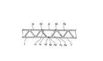
図1は本発明の一実施例で、中空アルミ押出し形材1,1′で構成された裏表に溶接線が生じる構体の一部を示している。図4のように、一般に鉄道車両構体は、主に左右の側構体ブロック,屋根構体ブロック,妻構体ブロック及び台枠ブロック等の構体ブロックより構成される。各構体ブロックを製作する場合、複数の中空アルミ押出し形材を作業盤上に並べ、溶接線10を溶接でつなぎあわせていく。図1は中空アルミ押出し形材1と隣合う別の中空アルミ押出し形材1′とを塞ぎ形材2を介して溶接で溶接した状況を示している。図1、図2から明らかなように、形材1は、実質的に平行な外板1aと内板1bと、両者を斜めに接続する複数の接続板である第3の板1cと、からなる。それぞれの接続板は外板1a、内板1bにトラス状に接続している。形材1の幅方向の端部において、外板1aの端部は内板1bの端部よりも突出している。端部の接続板は突出した外板1aの途中に接続している。内板1bの端部に2つの接続板が接続している。この接続部から内板1bの端部側に向けて板が突出している。この板の突出部は短い。この板は外板1a側に凹んだ位置にあり、凹部を設けている。凹部に塞ぎ形材2の端部が重なる。形材1′は形材1と同様の構成である。
【0009】
図2は図1で示した中空アルミ押出し形材同士1,1′の溶接状況の溶接方法を示している。構体ブロックの室外側の外板1aと外板1′aとを突合せて溶接を行う。その後、塞ぎ形材2を構体ブロックの室内側の内板1bと内板1′bをつなぐように設置し、溶接で溶接する。その後、塞ぎ形材2を構体ブロックの室内側の内板1b、内板1′bをつなぐように設置し、溶接で接合する。したがって、溶接作業は中空アルミ押出し形材の外板1a,1′aの溶接及び内板1b,1′bの溶接は、共に室内側からの作業ですむために、部材の反転作業も無く作業性が良い。
【0010】
図1及び図2での溶接は室内側からの作業を示したが、室外側からでもよい。
【0011】
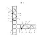
図3は本発明の一実施例で側梁形材5を含む台枠ブロック3と側構体ブロック4を溶接した状況を示している。本実施例の台枠ブロック3は、図1,図2で示した方法で製作したように室内側からの溶接で組上げている。例えば、側梁形材5の外板5aと台枠3の外板3aとを突合せて溶接する。その後、側梁形材5の内板5bと台枠3の内板3bとを塞ぎ形材2′を介して溶接する。このように製作した台枠ブロック3と側構体4とを室内外の両面溶接で溶接する。
【0012】
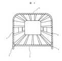
図4は図1ないし図3に示した方法で製作した側梁形材5を含む台枠ブロック3,側構体ブロック4,屋根構体6よりなる妻構体を除く車両構体を示す。
【0013】
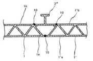
図5は本発明の一実施例で、側梁形材5を含む台枠ブロック3と側構体ブロック4を溶接した溶接部の状況を示している。本実施例は、台枠ブロック3に溶接された側梁形材5と側構体4の溶接作業を室内側から行った例である。即ち、側梁形材5の外板5aと側構体4の外板4aとを突合せて溶接する。その後、側梁形材5の内板5bと側構体4の内板4bとを塞ぎ形材2″を介して溶接する。
【0014】
上記と同様に各ブロック同士の接合は、中空アルミ押出し形材の室内側の内板及び室外側の外板共に、室内側の溶接作業で済ますことが出来る。
【0015】
図6は本発明の一実施例で、側梁形材5を含む台枠ブロック3と側構体ブロック4を溶接した溶接部の状況を示している。本実施例は、台枠ブロック3に溶接された側梁形材5と側構体4の溶接作業を室外側から行った例である。即ち、側梁形材5の内板5bと側構体4の内板4bとを突合せて溶接する。その後、側梁形材5の外板5aと側構体4の外板4aとを塞ぎ形材2″を介して溶接する。なお、側梁形材5を含む台枠ブロック3の製作は、この場合、室外側からの溶接作業で行った例を示している。
【0016】
上記と同様に各ブロック同士の接合は、中空アルミ押出し形材の室外側の外板及び室内側の内板共に、室外側の溶接作業で済ますことが出来る。要するに、室内側からの溶接で組上げる場合は、外板を先に溶接して、その後、内板を塞ぎ形材を介して溶接し、室外側からの溶接で組上げる場合は、内板を先に溶接して、その後、外板を塞ぎ形材を介して溶接する。
【0017】
図7は塞ぎ形材2′′が擬装部品の接合や強度上等の観点から所定の形状にしても良い。
【0020】
【発明の効果】
本発明によれば、少なくとも各構体ブロックを製作する場合、反転作業を行わずに溶接作業ができ、作業コストが低減できる。また、本発明によれば、中空アルミ押出し形材同士の接合に、室内側から或いは室外側から溶接作業が行える。
【図面の簡単な説明】
【図1】本発明の一実施例で構体ブロックの中空アルミ形材同士の接合部の断面図。
【図2】図1における実施例の溶接作業要領の一例を示した断面図。
【図3】本発明の一実施例で台枠ブロックと側構体ブロックの接合部の断面図。
【図4】本発明の一実施例で各構体ブロックを接合して構成される車両構体の横断面部の正面図。
【図5】本発明の一実施例で台枠ブロックと側構体ブロックの接合部の断面図。
【図6】本発明の一実施例で台枠ブロックと側構体ブロックの接合部の断面図。
【図7】本発明の一実施例で構体ブロックの中空アルミ形材同士の接合部の断面図。
【符号の説明】
1…中空アルミ形材、2…塞ぎ形材、3…台枠ブロック、4…側構体ブロック、5…側梁形材、6…屋根構体ブロック、10…溶接線。[0001]
BACKGROUND OF THE INVENTION
The present invention relates to a method for manufacturing a railway vehicle structure.
[0002]
[Prior art]
Is composed ofa plurality of hollow aluminum extruded shapemembers, mainly roof structure block, side structure block, the railway car body structure made of the underframe block, etc., because it has a weld line on the interior side and exterior side, it is necessary to double-sided welding . In the conventional structure manufacturing method, as in the method described in JP-A-6-270797, for example, when welding is performed from the indoor side, it is necessary to reverse the members and weld the outdoor side. Therefore, workability is poor because reversal work is performed during welding.
[0003]
[Problems to be solved by the invention]
In the prior art, the railway car body structure which weld line inside outof the hollow aluminum extruded shapemembers are made ofwood feesarising has a weld line on the interior side and exterior side, it is necessary to weld the two-sided, inverted working member The workability was poor because of
[0004]
It is an object of the present invention to easily perform welding work by welding from one side of the indoor side or the outdoor side so as not to invert the member when each structural block is manufactured by welding using a hollow aluminum extruded shapemember. It is to provide a method of manufacturing a railway vehicle structure that can be performed.
[0005]
[Means for Solving the Problems]
The above object is a method of manufacturing a railway vehicle structure comprising a roof structure block, a side structure block, and a underframe block using a plurality of hollow aluminum extruded shapes (1, 1 '). A first plate (1a), a second plate (1b) substantially parallel to the first plate, a third plate (1c) connecting the first plate and the second plate, A projecting portion (1a) from a connection portion between the first plate (1a) and the third plate (1c) of the hollow aluminum extruded shape member to an end portion of the first plate (1a) ′) Protrudes from the protruding portion (1b ′) from the connecting portion between the second plate (1b) and the third plate (1c) to the end of the second plate (1b). When producing the desired block, first, a plurality of hollow aluminum extruded shapes (1, 1 ') are prepared, and each of the hollow It said first plate(1a, 1'a) of Rumi extruded shape members together said end of (1a', 1'a') butt, when the first plate is positioned on the interior side of the railway car body structure The abutted portion is joined from the outside of the railway vehicle structure, or when the first plate is located outside the railway vehicle structure, the abutted portion is joined from the indoor side of the railway vehicle structure. After joining, the second of the hollow aluminum extruded shape (1 ') adjacent to the end (1b') of the second plate (1b) of one hollow aluminum extruded shape (1). The end portion (1′b ′) of the plate (1′b) is closed with a closing shape member (2), and each end portion of the closing shape member (2) is the secondplate. joined by weldingto,junction of該塞technique profile(2), when the first plate(1a, 1'a) is positioned at the outside side contact by welding from the interior side And, when said first plate(1a, 1'a) is positioned on the interior side it can be achieved by joining by welding from the outdoor side.
[0006]
As described above, the welding workability is improved because the welding is performed from one side without inverting the member.
[0007]
DETAILED DESCRIPTION OF THE INVENTION
Embodiments of the present invention will be described below with reference to FIGS.
[0008]
FIG. 1 shows an embodiment of the present invention, and shows a part of a structure in which weld lines are formed on the front and back sides formed of hollow aluminum
[0009]
FIG. 2 shows a welding method in which the hollow aluminum extruded
[0010]
Although welding in FIGS. 1 and 2 shows work from the indoor side, it may be from the outdoor side.
[0011]
FIG. 3 shows a state in which the
[0012]
FIG. 4 shows a vehicle structure excluding a wife structure composed of a
[0013]
FIG. 5 shows an embodiment of the present invention and shows a situation of a welded portion where the
[0014]
In the same manner as described above, the blocks can be joined to each other by welding on the indoor side of both the inner plate on the indoor side and the outer plate on the outdoor side of theextruded hollow aluminum material.
[0015]
FIG. 6 shows an embodiment of the present invention, and shows a situation of a welded portion where the
[0016]
In the same manner as described above, the blocks can be joined to each other by a welding operation on the outdoor side of both the outer outer plate and the inner inner plate of theextruded hollow aluminum material. In short, when assembling by welding from the inside of the room, the outer plate is welded first, then the inner plate is closed and welded via the shape material, and when assembling by welding from the outside of the room, the inner plate is First, the outer plate is closed and then welded via the profile.
[0017]
Figure 7is busy skills profile2 '' may be in a predetermined shape from the viewpoint of the bonding and strength Choicecamouflage component.
[0020]
【The invention's effect】
According to the present invention, when fabricating atleast the structure blocks can welding without inversion operationcan be reduced operating cost.Further, according to the present invention, welding work can be performed from the indoor side or from the outdoor side for joining the hollow aluminum extruded shapes.
[Brief description of the drawings]
FIG. 1 is a cross-sectional view of a joint portion between hollow aluminum shapes of a structure block in an embodiment of the present invention.
FIG. 2 is a cross-sectional view showing an example of a welding operation procedure of the embodiment in FIG.
FIG. 3 is a cross-sectional view of a joint portion between a frame block and a side structure block in one embodiment of the present invention.
FIG. 4 is a front view of a cross section of a vehicle structure formed by joining structure blocks in an embodiment of the present invention.
FIG. 5 is a cross-sectional view of a joint portion between a frame block and a side structure block in an embodiment of the present invention.
FIG. 6 is a cross-sectional view of a joint portion between a frame block and a side structure block in one embodiment of the present invention.
FIG. 7 is a cross-sectional view of a joint portion between hollow aluminum shapes of a structure block in one embodiment of the present invention.
[Explanation of symbols]
DESCRIPTION OF
Claims (6)
Translated fromJapanese前記中空アルミ押出し形材は、第1の板(1a)と、これに実質的に平行な第2の板(1b)と、前記第1の板と前記第2の板とを接続する第3の板(1c)と、からなり、
前記中空アルミ押出し形材の前記第1の板(1a)と前記第3の板(1c)との接続部から、該第1の板(1a)の端部までの突出部(1a´)は、前記第2の板(1b)と前記第3の板(1c)との接続部から該第2の板(1b)の端部までの突出部(1b´)よりも突出しており、
所望の前記ブロックを製作する際に、
まず、複数の中空アルミ押出し形材(1,1´)を準備し、それぞれの前記中空アルミ押出し形材の前記第1の板(1a,1´a)の前記端部同士(1a´,1´a´)を突合せ、
前記第1の板が鉄道車両構体の室内側に位置する際には、前記突合せた部分を鉄道車両構体の室外側から接合し、または前記第1の板が鉄道車両構体の室外側に位置する際には、前記突合せた部分を鉄道車両構体の室内側から接合し、
その後、一つの前記中空アルミ押出し形材(1)の前記第2の板(1b)の前記端部(1b´)と隣接する前記中空アルミ押出し形材(1´)の前記第2の板(1´b)の前記端部(1´b´)との間を塞ぎ形材(2)で塞ぎ、該塞ぎ形材(2)のそれぞれの端部をそれぞれの前記第2の板に溶接で接合し、
該塞ぎ形材(2)の接合は、前記第1の板(1a,1´a)が室外側に位置する場合は室内側から溶接で接合し、前記第1の板(1a,1´a)が室内側に位置する場合は室外側から溶接で接合すること、
を特徴とする鉄道車両構体の製作方法。In a method of manufacturing a railway vehicle structure composed of a roof structure block, a side structure block, and a underframe block by using a plurality of hollow aluminum extruded shapes (1, 1 '),
The hollow aluminum extruded shape member includes a first plate (1a), a second plate (1b) substantially parallel to the first plate (1a), and a third plate connecting the first plate and the second plate. Plate (1c), and
A protruding portion (1a ′) from the connection portion of the hollow aluminum extruded shape member from the first plate (1a) and the third plate (1c) to the end portion of the first plate (1a) is , Projecting from the projecting portion (1b ′) from the connecting portion between the second plate (1b) and the third plate (1c) to the end of the second plate (1b),
When producing the desired block,
First, a plurality of hollow aluminum extrudedshapes (1, 1 ') are prepared, and the end portions (1a', 1 ) of the first plates (1a, 1'a ) of the hollow aluminum extruded shapes, respectively. 'A')
When the first plate is located on the indoor side of the railway vehicle structure, the abutted portion is joined from the outdoor side of the railway vehicle structure, or the first plate is located on the outdoor side of the railway vehicle structure. At the time, the joined part is joined from the indoor side of the railway vehicle structure,
Thereafter, the second plate (1 ′) of the hollow aluminum extruded shape (1 ′) adjacent to the end (1b ′) of the second plate (1b) of one hollow aluminum extruded shape (1) ( 1′b) is closed between the end portions (1′b ′) with a closing shape member (2), and each end portion of the closing shape member (2)is welded to the secondplate . Joined,
Junction of該塞technique profile(2), when said first plate(1a, 1'a) is positioned on the outdoor side is joined by welding from the interior side, the first plate(1a, 1' When a) is located on the indoor side, welding from the outside of the room by welding,
A manufacturing method of a railway vehicle structure characterized by the above.
前記第3の板は複数あり、該複数の第3の板は前記第1の板および前記第2の板にトラス状に接続しており、
前記第2の板の前記端部と前記突出した前記第1の板の途中とを前記第3の板で接続しており、
前記第2の板の前記端部と前記トラス状の2つの前記第3の板との接続部に、前記塞ぎ形材を溶接で接合すること、
を特徴とする鉄道車両構体の製作方法。In the manufacturing method of the railway vehicle structure according to claim 1,
There are a plurality of the third plates, and the plurality of third plates are connected to the first plate and the second plate in a truss shape,
The end of the second plate and the middle of the protruding first plate are connected by the third plate,
Joining the closing shape member bywelding to the connecting portion between the end portion of the second plate and the two truss-shaped third plates;
A manufacturing method of a railway vehicle structure characterized by the above.
前記中空アルミ押出し形材は、第1の板と、これに実質的に平行な第2の板と、前記第1の板と前記第2の板とを接続する第3の板と、からなり、
前記中空アルミ押出し形材の前記第1の板の端部は該中空押出し形材の押出し方向に対して直交する幅方向において、前記第1の板の端部は前記第2の板の端部よりも突出しており、
それぞれの前記中空アルミ押出し形材の前記第1の板が鉄道車両構体の室外側または室内側にあり、
前記第1の板の前記端部同士の突合せ部を前記第1の板が室外にある場合は前記室内側から溶接で接合しており、前記第1の板が室内側にある場合は前記室外側から溶接で接合しており、
それぞれの前記中空アルミ押出し形材の前記第2の板の前記端部と隣接する前記中空アルミ押出し形材の前記第2の板の前記端部とを塞ぎ形材を介して溶接で接合しており、該塞ぎ形材の溶接で接合は、前記第1の板が室外側にある場合は、前記室内側から、前記第1の板が室内側にある場合は、前記室外側から、該塞ぎ形材の幅方向の端部を前記第2の板の端部に溶接で接合していること、
を特徴とする鉄道車両構体。In a railway vehicle structure comprising at least one of a roof structure block, a side structure block and a underframe block using a plurality of hollow aluminum extruded shapes,
The hollow aluminum extruded shape member includes a first plate, a second plate substantially parallel to the first plate, and a third plate connecting the first plate and the second plate. ,
An end of the first plate of the hollow aluminum extruded shape member is in a width direction orthogonal to an extrusion direction of the hollow extruded shape member, and an end portion of the first plate is an end portion of the second plate. Than protruding,
The first plate of each hollow aluminum extruded profile is on the exterior or interior side of the railway vehicle structure;
When the first plate is outside the room, the abutting portion between the end portions of the first plate is joined bywelding from the indoor side, and when the first plate is on the indoor side, the chamber We are joined from outside bywelding ,
The end portion of the second plate of each hollow aluminum extruded shape member and the end portion of the second plate of the hollow aluminum extruded shape shape member adjacent to each otherare joined bywelding via a closing shape member. cage, joinedby welding該塞skill profile, when the first plate is in the outdoor side from the indoor side, when the first plate is in the interior side, from the exterior side,該塞technique Joining the end in the width direction of the profile to the end of the second plate bywelding ;
A railway vehicle structure characterized by
前記第3の板は複数あり、該複数の第3の板は前記第1の板および前記第2の板にトラス状に接続しており、
前記第2の板の端部と前記突出した前記第1の板の途中とを前記第3の板で接続しており、
前記第2の板の前記端部と前記トラス状の2つの前記第3の板との接続部に、前記塞ぎ形材を溶接で接合していること、
を特徴とする鉄道車両構体。The railway vehicle structure according to claim 3,
There are a plurality of the third plates, and the plurality of third plates are connected to the first plate and the second plate in a truss shape,
The end of the second plate and the middle of the protruding first plate are connected by the third plate,
Bonding the closing shape member bywelding to the connection portion between the end portion of the second plate and the two truss-shaped third plates;
A railway vehicle structure characterized by
Priority Applications (1)
| Application Number | Priority Date | Filing Date | Title |
|---|---|---|---|
| JP03166096AJP3807766B2 (en) | 1996-02-20 | 1996-02-20 | Manufacturing method of railway vehicle structure |
Applications Claiming Priority (1)
| Application Number | Priority Date | Filing Date | Title |
|---|---|---|---|
| JP03166096AJP3807766B2 (en) | 1996-02-20 | 1996-02-20 | Manufacturing method of railway vehicle structure |
Related Child Applications (1)
| Application Number | Title | Priority Date | Filing Date |
|---|---|---|---|
| JP2002050837ADivisionJP2002264803A (en) | 2002-02-27 | 2002-02-27 | Double skin material for railway vehicle structures |
Publications (2)
| Publication Number | Publication Date |
|---|---|
| JPH09221024A JPH09221024A (en) | 1997-08-26 |
| JP3807766B2true JP3807766B2 (en) | 2006-08-09 |
Family
ID=12337310
Family Applications (1)
| Application Number | Title | Priority Date | Filing Date |
|---|---|---|---|
| JP03166096AExpired - LifetimeJP3807766B2 (en) | 1996-02-20 | 1996-02-20 | Manufacturing method of railway vehicle structure |
Country Status (1)
| Country | Link |
|---|---|
| JP (1) | JP3807766B2 (en) |
Cited By (2)
| Publication number | Priority date | Publication date | Assignee | Title |
|---|---|---|---|---|
| US9327736B2 (en) | 2010-10-05 | 2016-05-03 | Mitsubishi Heavy Industries, Ltd. | Method for manufacturing vehicle body frame |
| US11235816B2 (en) | 2018-03-12 | 2022-02-01 | Mitsubishi Heavy Industries, Ltd. | Double-skin structure and method of manufacturing thereof |
Families Citing this family (17)
| Publication number | Priority date | Publication date | Assignee | Title |
|---|---|---|---|---|
| CN1165403C (en) | 1996-03-19 | 2004-09-08 | 株式会社日立制作所 | Components for friction welding |
| AU733140B2 (en)* | 1998-09-29 | 2001-05-10 | Hitachi Limited | A friction stir welding method |
| TW464576B (en) | 1999-05-28 | 2001-11-21 | Hitachi Ltd | A structure body and a manufacturing method of a structure body |
| JP3481501B2 (en) | 1999-05-28 | 2003-12-22 | 株式会社日立製作所 | Structure and method of manufacturing the same |
| JP3563003B2 (en) | 1999-09-30 | 2004-09-08 | 株式会社日立製作所 | Friction stir welding method for structures |
| AT408644B (en)* | 1999-11-17 | 2002-01-25 | Siemens Sgp Verkehrstech Gmbh | BASE FOR A RAIL VEHICLE |
| JP3459210B2 (en) | 1999-11-24 | 2003-10-20 | 株式会社日立製作所 | Friction stir welding method |
| JP3538357B2 (en) | 2000-01-24 | 2004-06-14 | 株式会社日立製作所 | Friction stir welding method |
| JP3589930B2 (en) | 2000-02-25 | 2004-11-17 | 株式会社日立製作所 | Friction stir welding method |
| JP2002284001A (en)* | 2001-03-26 | 2002-10-03 | Kinki Sharyo Co Ltd | Panel structure and its manufacturing method |
| JP4494671B2 (en)* | 2001-06-04 | 2010-06-30 | 株式会社日立製作所 | Structure and manufacturing method thereof |
| JP4854715B2 (en)* | 2008-08-19 | 2012-01-18 | 川崎重工業株式会社 | Railcar side structure |
| CN104583046B (en)* | 2012-09-20 | 2016-10-12 | 株式会社日立制作所 | Car structure |
| JP6452494B2 (en)* | 2015-03-02 | 2019-01-16 | 日本車輌製造株式会社 | Railway vehicle |
| JP7025847B2 (en)* | 2017-04-03 | 2022-02-25 | 川崎車両株式会社 | Railroad vehicle structure |
| JP6944324B2 (en) | 2017-09-26 | 2021-10-06 | 川崎重工業株式会社 | Railroad vehicle structure |
| JP7361331B2 (en)* | 2019-10-15 | 2023-10-16 | 川崎車両株式会社 | Joint structure, structure, and structure |
- 1996
- 1996-02-20JPJP03166096Apatent/JP3807766B2/ennot_activeExpired - Lifetime
Cited By (2)
| Publication number | Priority date | Publication date | Assignee | Title |
|---|---|---|---|---|
| US9327736B2 (en) | 2010-10-05 | 2016-05-03 | Mitsubishi Heavy Industries, Ltd. | Method for manufacturing vehicle body frame |
| US11235816B2 (en) | 2018-03-12 | 2022-02-01 | Mitsubishi Heavy Industries, Ltd. | Double-skin structure and method of manufacturing thereof |
Also Published As
| Publication number | Publication date |
|---|---|
| JPH09221024A (en) | 1997-08-26 |
Similar Documents
| Publication | Publication Date | Title |
|---|---|---|
| JP3807766B2 (en) | Manufacturing method of railway vehicle structure | |
| CN1322241C (en) | Friction welding method and structure body formed by friction welding | |
| JP2000118438A (en) | Extruded material frame connection structure for automobile | |
| JPH0999857A (en) | Car body structure | |
| KR20040039247A (en) | Hollow frame member for friction stir joining method | |
| KR910000456A (en) | Railroad car system and its manufacturing method | |
| JPH01309870A (en) | Body structure for rolling stock | |
| JPH10175542A (en) | Railcar structure | |
| JP3189695B2 (en) | Vehicle structure | |
| JP2002264803A (en) | Double skin material for railway vehicle structures | |
| JPH06183340A (en) | Railway vehicle structure | |
| JPH1035487A (en) | Vehicle structure and manufacturing method thereof | |
| JP2023030590A (en) | Railway vehicle body structure and railway vehicle | |
| JPH10329709A (en) | Joint structure of railway vehicle structure | |
| JP3597447B2 (en) | Structure formation structure of railway vehicle | |
| JPH0333574Y2 (en) | ||
| JPS6019018Y2 (en) | Center pillar upper joint structure | |
| KR100643254B1 (en) | Railway vehicle body structure and joint structure for friction stir welding | |
| JPH085903Y2 (en) | Car body structure | |
| JP4402062B2 (en) | Friction stir welding method | |
| JP3224096B2 (en) | Friction joining method and structure | |
| JP2537615B2 (en) | Body floor structure | |
| KR200142187Y1 (en) | Welding structure of multi-fold panel | |
| JP6909019B2 (en) | Railroad vehicle structure | |
| KR200151813Y1 (en) | Side wall structure of electric car |
Legal Events
| Date | Code | Title | Description |
|---|---|---|---|
| A131 | Notification of reasons for refusal | Free format text:JAPANESE INTERMEDIATE CODE: A131 Effective date:20040518 | |
| A521 | Written amendment | Free format text:JAPANESE INTERMEDIATE CODE: A523 Effective date:20040709 | |
| A131 | Notification of reasons for refusal | Free format text:JAPANESE INTERMEDIATE CODE: A131 Effective date:20041116 | |
| A521 | Written amendment | Free format text:JAPANESE INTERMEDIATE CODE: A523 Effective date:20050112 | |
| A131 | Notification of reasons for refusal | Free format text:JAPANESE INTERMEDIATE CODE: A131 Effective date:20050426 | |
| A521 | Written amendment | Free format text:JAPANESE INTERMEDIATE CODE: A523 Effective date:20050615 | |
| A131 | Notification of reasons for refusal | Free format text:JAPANESE INTERMEDIATE CODE: A131 Effective date:20051018 | |
| A521 | Written amendment | Free format text:JAPANESE INTERMEDIATE CODE: A523 Effective date:20051208 | |
| TRDD | Decision of grant or rejection written | ||
| A01 | Written decision to grant a patent or to grant a registration (utility model) | Free format text:JAPANESE INTERMEDIATE CODE: A01 Effective date:20060516 | |
| A61 | First payment of annual fees (during grant procedure) | Free format text:JAPANESE INTERMEDIATE CODE: A61 Effective date:20060516 | |
| R150 | Certificate of patent or registration of utility model | Free format text:JAPANESE INTERMEDIATE CODE: R150 | |
| FPAY | Renewal fee payment (event date is renewal date of database) | Free format text:PAYMENT UNTIL: 20100526 Year of fee payment:4 | |
| FPAY | Renewal fee payment (event date is renewal date of database) | Free format text:PAYMENT UNTIL: 20110526 Year of fee payment:5 | |
| FPAY | Renewal fee payment (event date is renewal date of database) | Free format text:PAYMENT UNTIL: 20110526 Year of fee payment:5 | |
| FPAY | Renewal fee payment (event date is renewal date of database) | Free format text:PAYMENT UNTIL: 20120526 Year of fee payment:6 | |
| FPAY | Renewal fee payment (event date is renewal date of database) | Free format text:PAYMENT UNTIL: 20120526 Year of fee payment:6 | |
| FPAY | Renewal fee payment (event date is renewal date of database) | Free format text:PAYMENT UNTIL: 20130526 Year of fee payment:7 | |
| FPAY | Renewal fee payment (event date is renewal date of database) | Free format text:PAYMENT UNTIL: 20130526 Year of fee payment:7 | |
| EXPY | Cancellation because of completion of term |