JP3807583B2 - Road area determination device - Google Patents
Road area determination deviceDownload PDFInfo
- Publication number
- JP3807583B2 JP3807583B2JP11096499AJP11096499AJP3807583B2JP 3807583 B2JP3807583 B2JP 3807583B2JP 11096499 AJP11096499 AJP 11096499AJP 11096499 AJP11096499 AJP 11096499AJP 3807583 B2JP3807583 B2JP 3807583B2
- Authority
- JP
- Japan
- Prior art keywords
- road
- window
- area
- determined
- road area
- Prior art date
- Legal status (The legal status is an assumption and is not a legal conclusion. Google has not performed a legal analysis and makes no representation as to the accuracy of the status listed.)
- Expired - Fee Related
Links
Images


Classifications
- B—PERFORMING OPERATIONS; TRANSPORTING
- B60—VEHICLES IN GENERAL
- B60R—VEHICLES, VEHICLE FITTINGS, OR VEHICLE PARTS, NOT OTHERWISE PROVIDED FOR
- B60R16/00—Electric or fluid circuits specially adapted for vehicles and not otherwise provided for; Arrangement of elements of electric or fluid circuits specially adapted for vehicles and not otherwise provided for
- B60R16/02—Electric or fluid circuits specially adapted for vehicles and not otherwise provided for; Arrangement of elements of electric or fluid circuits specially adapted for vehicles and not otherwise provided for electric constitutive elements
- B60R16/023—Electric or fluid circuits specially adapted for vehicles and not otherwise provided for; Arrangement of elements of electric or fluid circuits specially adapted for vehicles and not otherwise provided for electric constitutive elements for transmission of signals between vehicle parts or subsystems
- B60R16/0237—Electric or fluid circuits specially adapted for vehicles and not otherwise provided for; Arrangement of elements of electric or fluid circuits specially adapted for vehicles and not otherwise provided for electric constitutive elements for transmission of signals between vehicle parts or subsystems circuits concerning the atmospheric environment
- G—PHYSICS
- G01—MEASURING; TESTING
- G01S—RADIO DIRECTION-FINDING; RADIO NAVIGATION; DETERMINING DISTANCE OR VELOCITY BY USE OF RADIO WAVES; LOCATING OR PRESENCE-DETECTING BY USE OF THE REFLECTION OR RERADIATION OF RADIO WAVES; ANALOGOUS ARRANGEMENTS USING OTHER WAVES
- G01S11/00—Systems for determining distance or velocity not using reflection or reradiation
- G01S11/12—Systems for determining distance or velocity not using reflection or reradiation using electromagnetic waves other than radio waves
- G—PHYSICS
- G08—SIGNALLING
- G08G—TRAFFIC CONTROL SYSTEMS
- G08G1/00—Traffic control systems for road vehicles
- G08G1/01—Detecting movement of traffic to be counted or controlled
- G08G1/04—Detecting movement of traffic to be counted or controlled using optical or ultrasonic detectors
Landscapes
- Physics & Mathematics (AREA)
- Engineering & Computer Science (AREA)
- General Physics & Mathematics (AREA)
- Environmental & Geological Engineering (AREA)
- Radar, Positioning & Navigation (AREA)
- Remote Sensing (AREA)
- Life Sciences & Earth Sciences (AREA)
- Biodiversity & Conservation Biology (AREA)
- Electromagnetism (AREA)
- Environmental Sciences (AREA)
- Mechanical Engineering (AREA)
- Measurement Of Optical Distance (AREA)
- Image Processing (AREA)
- Image Analysis (AREA)
- Length Measuring Devices By Optical Means (AREA)
- Traffic Control Systems (AREA)
Description
Translated fromJapanese【0001】
【発明の属する技術分野】
この発明は、自動車などの車両に搭載されたカメラによる撮像手段を用いて、道路領域を検出する装置に関する。
【0002】
【従来の技術】
近年、車両走行の安全性を向上させるため、自車両の前方にある対象物までの距離や大きさを判断し、これに応じて車両を適切に制御する装置が提案されている。
【0003】
2つの受光素子からなる光学式距離計測装置を使用し、距離検出された被写体が物体か道路領域(路面上の文字/白線を含む)かを判断する手法に関連するものとして、特開平7−225126号公報には、車両前方の物体を正しく認識することができる路上物体認識装置が記載されている。この装置は、車両の走行路面上を撮像するステレオカメラを備え、カメラで得られた画像を複数のウィンドウに分割して、ウィンドウごとに被写体までの距離を算出する。この被写体までの距離と、ウィンドウの行レンジごとに決まる基準距離とを比較して車両前方の物体を認識する。
【0004】
【発明が解決しようとする課題】
特開平7−225126号公報のものでは、路面が自車両の前に水平に存在しているものとして、カメラで撮像した被写体が物体か道路領域かの判断を行うので、自車両がピッチングやローリングで傾いたり、自車両の前方が坂道やバンクになっている場合は、路面上の物体を道路領域と間違えて判断したり、道路領域を物体と間違えて判断することがある。
【0005】
そこでこの発明は、自車両がピッチングやローリングで傾いたり、走行路面が坂道やバンクでも、物体と道路とを間違えることなく道路領域を検出することのできる装置を提供することを目的とする。さらに、この発明は、検出された道路領域に基づいて、道路上の物体(他車両や障害物を含む)を検出する装置を提供することを目的とする。
【0006】
【課題を解決するための手段】
上記の課題を解決するため、請求項1の発明の道路領域判定装置は、少なくとも1つの撮像手段と、前記撮像手段から得られ、複数のウィンドウに分割した画像から、自車両の直前の画像領域を含む複数のウィンドウの輝度値を取得し、該複数の輝度値に基づいて基準輝度値を抽出する抽出手段と、少なくとも1つの他のウィンドウの輝度値を前記基準輝度値と比較し、所定範囲内にあれば、該他のウィンドウの画像領域を道路領域と判定する判定手段とを備える。
【0007】
この発明によると、路面の位置ではなく路面自体を検出するので、自車両がピッチングやローリングで傾いたり自車両の前方が坂道またはバンクであっても物体と道路とを間違えることなく道路領域を判定することができる。
【0008】
また、請求項2の発明は、請求項1の道路領域判定装置において、前記判定手段で道路領域と新たに判定された前記他のウィンドウの輝度値を、新たな基準輝度値とする基準輝度値変更手段を備える。
【0009】
請求項2の発明によると、より近傍にある道路領域の輝度値と輝度値の比較を行うことができるので、より精密に道路領域を判定することができる。
【0010】
また、請求項3の発明は、請求項1または請求項2の道路領域判定装置において、前記撮像手段を少なくとも2つ有して、所定の間隔をおいて配置し、該少なくとも2つの撮像手段で得られる少なくとも2つの画像に基づいて対象物までの距離を計測する計測手段を備え、前記判定された道路領域に基づいて道路上の物体を検出し、前記計測手段により該物体までの距離を計測する。
【0011】
請求項3の発明によると、検出された道路領域に基づいて、道路上の他車両や障害物を検出することができる。
【0012】
また、請求項4の発明は、請求項1から請求項3の道路領域判定装置において、前記判定手段において、あるウィンドウについての前記比較が所定範囲内にないとき、該あるウィンドウの計測距離および道路領域と判定された他のウィンドウの計測距離に基づいて、該あるウィンドウの画像領域が道路上の標識領域かどうか判断する。
【0013】
請求項4の発明によると、路面上の標識領域を正確に抽出して認識することができる。
【0014】
また、請求項5の発明は、請求項1から請求項4の道路領域判定装置において、ウィンドウが少なくとも1つの画素から構成される。
【0015】
請求項5の発明によると、画像の画素単位から道路領域が判定されるので、より精密に道路領域を判定することができる。
【0016】
【発明の実施の形態】
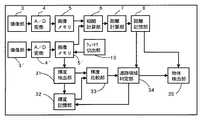
次に図面を参照してこの発明の実施の形態を説明する。図1は、この発明の一実施例の道路領域判定装置の全体的なブロック図である。図2は、この実施例で用いる三角計測法による距離の計測原理を説明する図である。まず図2を参照して1対の撮像装置を用いた距離の測定方法を説明する。
【0017】
一対の撮像装置の一方を構成するラインセンサ21およびレンズ23は、他方の撮像装置を構成するラインセンサ22およびレンズ24と所定の間隔すなわち基線長Bだけ左右方向または上下方向に間隔をおいて配置されている。ラインセンサ21および22は、典型的には1次元のCCDであり、直線的に配列されたフォトセンサのアレイであってもよい。夜間の使用を考慮すると赤外線を用いた撮像装置にするのがよい。この場合、レンズ23、24の前に赤外線透過性のフィルタを置き、赤外線の光源を用いて一定の周期で対象物20を照射し、対象物20から反射する赤外線をラインセンサ21、22が感知するようにするのがよい。
【0018】
ラインセンサ21、22は、それぞれレンズ23、24の焦点距離fに配置されている。レンズ23、24のある平面から距離aにある対象物の像が、ラインセンサ21ではレンズ23の光軸からX1ずれた位置に形成され、ラインセンサ22ではレンズ24の光軸からX2だけずれた位置に形成されるとすると、レンズ23、24の面から対象物20までの距離aは、三角計測法の原理により、a=B・f/(X1+X2)で求められる。
【0019】
この実施例では画像はデジタル化されるので、距離(X1+X2)は、ディジタル的に算出される。ラインセンサ21および22で得られる画像の片方または両方をシフトさせながら両画像のそれぞれ対応する画素の輝度を示すディジタル値の差の絶対値の総和を求め、これを相関値とする。相関値が最小値になるときの画像のシフト量が両画像の間の位置ずれ、すなわち(X1+X2)を示す。観念的には図2に示すようにラインセンサ21および22から得られる2つの画像を重なり合わせるために2つの画像を相対的に移動させねばならない距離が(X1+X2)である。
【0020】
ここでは、簡単のため撮像装置が1次元のラインセンサ21、22であるものとして説明したが、以下に述べるようにこの発明の一実施例では2次元のCCDまたは2次元のフォトセンサ・アレイを撮像装置として使用する。この場合、2つの撮像装置から得られる2次元の画像を相対的にシフトさせて上述したのと同様の相関計算を行い、相関値が最小となるときのシフト量を求めると、このシフト量が(X1+X2)に相当する。
【0021】
図1の撮像手段3は、図2のレンズ23およびラインセンサ21からなる一方の撮像手段に対応し、撮像手段3’は、図2のレンズ24およびラインセンサ22からなる他方の撮像手段に対応する。この実施例では、図3の(b)に示すように撮像領域を複数のウィンドウ(小領域)W11、W12、・・・に分割し、ウィンドウごとに距離の計測を行うので、対象物全体の2次元の画像が必要になる。このため撮像手段3、3’は、2次元のCCDアレイまたは2次元のフォトセンサ・アレイで構成される。
【0022】
図3の(a)は、撮像手段3または3’により自車両の前方を走行する他車両を撮像した画像の例を示し、図3の(b)は、図3の(a)の画像を概念的に複数のウィンドウに分割したものを示す。図3の(b)は、縦方向に行および横方向に列をとり、簡単のため10行×15列のウィンドウに分割して示す。それぞれのウィンドウには番号が付されており、例えばW12は、1行2列にあるウィンドウを示す。
【0023】
撮像手段3、3’で撮像された対象物の画像はアナログ・デジタル変換器(A/D変換器)4、4’でデジタルデータに変換され、画像メモリ5、5’に格納される。ウィンドウ切り出し部13によって、ウィンドウW11に対応する画像部分が画像メモリ5および5’からそれぞれ切り出されて相関計算部6に送られる。相関計算部6は、切り出された2つの画像を所定の単位ずつシフトさせて前述した相関計算を行い相関値が最小になるときのシフト量を求めると、このシフト量が(X1+X2)である。相関計算部6は、こうして求めた(X1+X2)の値を距離計算部7に送る。
【0024】
距離計算部7は、前述したa=B・f/(X1+X2)の式を用いて、ウィンドウW11にある対象物までの距離a11を求める。こうして求められた距離a11は、距離記憶部8に記憶される。同様の計算処理がそれぞれのウィンドウについて順次実行され、距離a11、a12、・・・が距離記憶部8に記憶される。
【0025】
この距離の計算は、以下に述べる道路領域判定部34および物体検出部35が使用するのに必要なウィンドウについてのみ実行することもできる。以下、あるウィンドウについて計算された対象物までの距離を、そのウィンドウの計測距離という。
【0026】
上の相関計算で用いる画像データは、撮像素子アレイの素子のピッチによって分解能が定まるので、フォトセンサ・アレイなど比較的ピッチの大きい受光素子を用いるときは、ピッチ間の補間計算を行って画像データの密度を高める処理を行い、こうして密度を高められた画像データについて相関計算を行うのが好ましい。
【0027】
また、温度による撮像素子アレイの特性変化を補正するため、温度センサを撮像素子アレイ付近に配置し、温度センサから得られる温度情報に基づいて距離計算を補正するようにすることもできる。
【0028】
次に、図1および図3を参照して、画像における道路領域の判定を説明する。前述したように、図3の(b)は、10行×15列のウィンドウに分割されているけれども、実際には画像領域は非常に細かく分割される。より精密に道路領域を判定するため、それぞれのウィンドウを1つの画素から構成することができる。または、複数の画素が合わさって1つのウィンドウを構成してもよい。それぞれのウィンドウは、上記述べた距離を計測するのに使用されるウィンドウと同じ大きさでもよく、異なる大きさでもよい。
【0029】
撮像手段3’から得られ、デジタルデータに変換された画像が画像メモリ5’に記憶されると、図1のウィンドウ切り出し部13は、画像メモリ5’から、車両直前の画像領域を含む複数のウィンドウを切り出す。輝度抽出部31は、切り出されたウィンドウから複数の輝度値を取得する。
【0030】
車両直前の画像領域を含むウィンドウの輝度値を取得するのは、自車両直前の画像領域は道路である可能性が非常に高いからであり、複数の輝度値を取得するのは、路面上に文字/白線などの標識領域があっても、本来の道路の輝度値を取得できるようにするためである。入力画像のどのウィンドウを、自車両直前の画像領域を含む複数のウィンドウとして取得するかは、車両の大きさおよび撮像装置の車両内における位置などに応じて予め定められる。
【0031】
次に、本来の道路の輝度値を抽出するため、取得した複数の輝度値から、路面上の標識を含むウィンドウの輝度値を取り除く。たとえば、画像の最下行のウィンドウに路面上の標識のウィンドウがいくつか含まれる場合、一般に路面上の標識の輝度は道路の輝度と非常に異なるので、この行のウィンドウの輝度値にはわずかなばらつきが生じる。したがって、この行のウィンドウの輝度値を平均し、平均値から所定値以上離れた値の輝度値を取り除くことができる。
【0032】
または、路面上の標識の色は主に白または黄であり、道路の色と非常に異なるので、白または黄に対応する範囲の輝度値を取り除くこともできる。さらに、前回入力された画像から抽出された基準輝度値に基づいて、今回入力された画像から取得した輝度値が本来の道路の輝度値かどうか推定することもできる。
【0033】
路面上の標識を含むウィンドウの輝度値を取り除いた後、輝度抽出部31は、残った輝度値に基づいて基準輝度値を抽出し、輝度記憶部32に記憶する。残った輝度値のうち1または複数の輝度値を選択して、基準輝度値として記憶することができる。または、複数の輝度値を平均した値を1つの基準輝度値として記憶することもできる。輝度値は、たとえば256の階調(真黒「0」から真白「255」の間)を持つデジタルデータとして表すことができる。
【0034】
次に、ウィンドウ切り出し部13は画像から他のウィンドウを切り出し、輝度抽出部31は、そのウィンドウの輝度値を抽出する。輝度比較部33は、抽出された輝度値と、輝度記憶部32に格納された基準輝度値とを比較する。
【0035】
それぞれのウィンドウが複数の画素から構成される場合には、それぞれの画素の輝度値の和の平均をとり、その平均値をウィンドウの輝度値として抽出することができる。また、輝度値を抽出して比較する処理は、上記の距離を計算する処理と並列して実行することができる。
【0036】
道路領域判定部34は、輝度比較部33から受け取った比較結果に基づいて、道路領域の判定を行う。比較結果が所定範囲内にあれば、ウィンドウを道路領域と判定する。これは、道路領域は輝度が似ており、前方を走行する車両などとは輝度が異なるからである。道路領域と判定したウィンドウの輝度値は、新たな輝度値として輝度記憶部32に記憶される。
【0037】
図3の(b)を参照して、輝度値に基づいた道路領域の判定を例を説明する。車両直前の画像領域を含むウィンドウWA7およびWA9(斜線で塗りつぶされたウィンドウ)がウィンドウ切り出し部13により切り出され、輝度抽出部31は、それぞれのウィンドウの輝度値L1およびL2を抽出し、基準輝度値として輝度記憶部32に記憶する。次に、ウィンドウWA7に隣接するウィンドウWA6が切り出され、輝度抽出部31はウィンドウWA6の輝度値を抽出する。輝度比較部33は、抽出した輝度値と基準輝度値L1とを比較する。道路領域判定部34は、比較した結果が所定範囲内ならば(例えば、基準輝度値に対して±3の範囲を所定範囲とすることができる)、ウィンドウWA6を道路領域と判定し、ウィンドウWA6の輝度値を、新たな基準輝度値L3として輝度記憶部32に記憶する。
【0038】
次に、ウィンドウWA6に隣接するウィンドウWA5が切り出され、輝度抽出部31により、ウィンドウWA5の輝度値が抽出される。輝度比較部33は、抽出した輝度値と基準輝度値L3とを比較する。道路領域判定部34は、比較した結果が所定範囲内ならば、ウィンドウWA5を道路領域と判定し、ウィンドウWA5の輝度値を、新たな基準輝度値L4として輝度記憶部32に記憶する。このように、画像からウィンドウが順次切り出され、ウィンドウごとに輝度値を比較して道路領域を判定する。
【0039】
ウィンドウ切り出し部13により切り出されるウィンドウは、基準輝度値を持つウィンドウの近傍にあるのが好ましい。具体的には、基準輝度値がウィンドウWA6の輝度値である場合、ウィンドウWA6と同じ行に属するウィンドウまたは隣接する行に属するウィンドウを切り出して輝度値を比較するのが好ましい。比較する2つのウィンドウの計測距離の差が大きいと、同じ道路でも輝度値が実質的に異なることがあるからである。この実施例によると、画像内の道路の輝度が、自車両からの距離に応じて変化する場合でも、正確に道路領域を検出することができる。
【0040】
上記の実施例のように、道路領域と判定された輝度値を新たな輝度値とせずに、一番最初に車両直前の画像領域を含むウィンドウから抽出された輝度値(上記の例では、L1およびL2)を一定の基準輝度値とし、これに対して画像のそれぞれのウィンドウの輝度値を比較して道路領域を判定することもできる。
【0041】
さらに、上記の実施例では、1つの撮像手段3'から得られた1つの画像に基づいて輝度値が抽出されるけれども、前述した距離計測に必要な2またはそれ以上の撮像手段で得られた2またはそれ以上の画像を用いて抽出してもよい。例えば、撮像手段3で得られた画像から基準輝度値L2を抽出し、撮像手段3’で得られた画像から基準輝度値L1を抽出することができる。
【0042】
輝度値を比較して道路領域を判定する処理は、何らかの並列処理をするのが好ましい。例えば、ウィンドウWA1〜WA6およびW91〜W97の輝度値を基準輝度値L1と一括して比較し、次にウィンドウW81〜W87の輝度値を、例えば新たな基準輝度値となったウィンドウW93の輝度値と一括して比較するというように、ウィンドウを行単位で処理することができる。また、高速に処理するため、基準輝度値L1を基点として画像の左半分のウィンドウを処理し、基準輝度値L2を基点として画像の右半分のウィンドウを処理し、両者を並列に処理するのが好ましい。
【0043】
なお、道路領域と判定された画像領域に囲まれた領域を、自動的に道路領域と判定することができる。これにより、例えば道路領域と判定された領域に囲まれた領域が、道路とは異なる輝度を持つ標識領域でも、この標識領域を道路領域と判定することができる。道路領域で囲まれた領域がどのくらいの大きさならば道路領域と判定できるかは、どのくらいの大きさの物体を検出するかに依存して定められる。
【0044】
こうして、輝度値に基づいて路面自体を検出するので、自車両がピッチングやローリングで傾いたり坂道やバンクを走行していても道路領域を判定することができ、判定された道路領域には他の車両や障害物がないと判断することができる。
【0045】
ここで、ウィンドウの計測距離を使用して、道路上の標識領域を正確に抽出することができる。道路領域判定部34は、比較結果が所定範囲内にないと判断されたウィンドウの計測距離を距離記憶部8から取得し、この距離が道路までの距離かどうかを判断する。道路までの距離ならば、このウィンドウを道路上の標識領域と判定することができる。
【0046】
ウィンドウの道路までの距離は、道路領域と判定された他のウィンドウの計測距離(すなわち、道路までの計測距離)から推定することができる。例えば、他のウィンドウが属する行に含まれるすべてのウィンドウについて、道路までの距離は同じと推定することができる。さらに、道路と判定されたウィンドウの計測距離から、ウィンドウの行ごとに道路までの距離を推定することができる。したがって、道路領域判定部34は、ウィンドウについて実際に計測された距離と、推定された道路までの距離とを比較して、ウィンドウの画像領域が道路上の標識領域かどうか判断することができる。
【0047】
たとえば、図3の(b)に示すように、ウィンドウW95は路面上の文字を含む。道路領域判定部34は、ウィンドウW95についての比較結果を受け取り、比較結果が所定範囲内にないので、距離記憶部8からウィンドウW95の計測距離を取得する。さらに、例えばウィンドウW95と同じ行に属し、道路領域と判定された他のウィンドウW93の計測距離を距離記憶部8から取得する。2つの距離を比較した結果、実質的に同じ距離なので、ウィンドウW95の画像領域を路面上の標識領域と判定する。このような判定を繰り返すことにより、図3の(b)に示すような道路上の標識「60」を認識することができる。
【0048】
上記のように、計測距離を使用して道路上の標識領域を抽出して認識することができるので、例えばスピードの出しすぎや車線変更などについて運転者の注意を喚起するよう車両を制御することもできる。
【0049】
これまで説明した道路領域の判定は、撮像手段から入力された画像の全領域について実行してもよく、または一部の領域についてのみ実行してもよい。例えば、前回入力された画像に対して、自車両の走行とともに新たに画像として入力された画像領域についてのみ実行することができる。さらに、カーナビゲーションシステムの予め設定された道路モデルを使用して、道路領域を判定することができる。このように、判定を行う画像領域を限定することで、より効率よく道路領域の判定を行うことができる。
【0050】
道路領域が判定されたので、画像内のウィンドウは、道路領域のものと道路領域以外のものとに分類される。道路領域判定部34は、道路領域と判定されたウィンドウから構成される道路領域を、必要に応じて画像の形で出力することができる。図3の(c)はこの出力画像の例であり、検出された道路領域が塗りつぶされて表示されている。
【0051】
物体検出部35は、道路領域判定部34で判定された道路領域に基づき、道路上にある物体を検出する。道路領域が判定されたので、道路領域の前方にあり、道路領域と判定されなかったウィンドウを抽出することにより、物体を検出することができる。
【0052】
たとえば、図3の(c)に示すように道路領域が判定されたので、道路領域を前方にたどり、道路領域と判定されなかったウィンドウW57、W58、W59を抽出する。図3の(b)に示すように、これらのウィンドウは前方を走行する他の車両を含む。物体検出部35は、これらのウィンドウの計測距離を距離記憶部8から取得する。取得した計測距離から、自車両から他車両までの距離を検出することができる。さらに、道路領域と判定されたウィンドウW66〜W6Aに対する物体領域のウィンドウW57、W58、W59の位置から、他車両が道路の中央にあると判断することができる。
【0053】
このように、物体検出部35は、検出した物体までの距離に基づき前方を走行する他車両との車間距離を検出することができるので、この車間距離について運転者に警告することができる。また、道路前方に車両の走行を妨げる障害物がある場合には、アラームを鳴らして運転者に注意を喚起することもできる。
【0054】
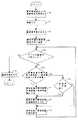
図4は、道路領域を判定するルーチンのフローチャートであり、ソフトウェアプログラムを使用して実行することができる。このルーチンは、一定周期で入力された画像ごとに繰り返し実行される。この例では、ウィンドウが1つの画素から構成されており、基準輝度値を持つ画素を出発点として、隣接する画素の輝度値を基準輝度値と比較する。画素が道路領域と判定されると、その画素の輝度値を新たな基準輝度値とする。
【0055】
最初に、基準輝度値および道路領域が初期化され(ステップ40)、画像メモリ5’に格納された画像が読み込まれる(ステップ41)。この画像は、複数の画素に分割されている。ステップ42に進み、入力した画像から、車両直前の画像領域を含む複数の画素の輝度値に基づいて基準輝度値を抽出し、輝度記憶部32に記憶する。
【0056】
ステップ43では、基準輝度値を持つ画素を最初の探索位置とする。探索位置は、道路領域の判定が行われた画素を指す。ステップ44では、すべての画素について道路領域が判定されたかどうか判断する。判定されていない画素が残っているならば、その画素を処理するためステップ45に進む。
【0057】
ステップ45では、探索位置に隣接する画素の輝度値が基準輝度値と比較され、所定範囲内ならば、ステップ47に進む。比較結果が所定範囲内でなければ、ステップ46に進み、探索位置に隣接する画素の計測距離が道路までの距離かどうか判断する。例えば、探索位置の画素が道路領域と判定されていれば、この画素の計測距離と比較し、実質的に同じならば、探索位置の隣の画素の計測距離は道路までの距離と判断することができる。探索位置の隣の画素の計測距離が道路までの距離と判断されれば、ステップ48に進む。道路までの距離と判断されなければ、ステップ49に進み、探索位置に隣接する画素を、次の探索位置とする。
【0058】
ステップ47では、ステップ45で道路領域と判定された画素の輝度値を、新たな基準輝度値とする。ステップ45で道路領域と判定された画素は、道路上の文字/白線を含まないからである。ステップ48では、探索位置の隣の画素を道路領域と判定する。ステップ49に進み、探索位置に隣接する画素を、次の探索位置とする。ステップ44で、すべての画素が道路かどうか判定されたならば、ステップ50に進み、画像において検出された道路領域を出力する。
【0059】
【発明の効果】
請求項1の発明によると、路面の位置ではなく路面自体を検出するので、自車両がピッチングやローリングで傾いたり自車両の前方が坂道またはバンクであっても物体と道路とを間違えることなく道路領域を判定することができる。
【0060】
請求項2の発明によると、より近傍にある道路領域の輝度値と輝度値の比較を行うことができるので、より精密に道路領域を判定することができる。
【0061】
請求項3の発明によると、検出された道路領域に基づいて、道路上の他車両や障害物を検出することができる。請求項4の発明によると、道路上の標識領域を正確に抽出して認識することができる。また、請求項5の発明によると、画像の画素単位から道路領域を判定するので、より精密に道路領域を判定することができる。
【図面の簡単な説明】
【図1】この発明の一実施例の全体的な構成を示すブロック図。
【図2】三角計測法による距離の計測原理を説明するための図。
【図3】この発明による、(a)撮像された画像、(b)距離および道路領域判定のため小領域(ウィンドウ)に分割された画像、および(c)出力された画像を示す図。
【図4】道路領域を判定するプロセスを示すフローチャート。
【符号の説明】
3、3’ 撮像部 31 輝度抽出部 32 輝度記憶部
33 輝度比較部 34 道路領域判定部 35 物体検出部[0001]
BACKGROUND OF THE INVENTION
The present invention relates to an apparatus for detecting a road area by using an imaging means by a camera mounted on a vehicle such as an automobile.
[0002]
[Prior art]
In recent years, in order to improve the safety of vehicle travel, an apparatus has been proposed that determines the distance and size to an object ahead of the host vehicle and appropriately controls the vehicle accordingly.
[0003]
As a method related to a method for determining whether a subject whose distance has been detected is an object or a road area (including characters / white lines on a road surface) using an optical distance measuring device including two light receiving elements, Japanese Patent Laid-Open No. 7-7 Japanese Patent No. 225126 describes a road object recognition apparatus that can correctly recognize an object in front of a vehicle. This apparatus includes a stereo camera that captures an image on the road surface of a vehicle, divides an image obtained by the camera into a plurality of windows, and calculates a distance to a subject for each window. An object ahead of the vehicle is recognized by comparing the distance to the subject with a reference distance determined for each row range of the window.
[0004]
[Problems to be solved by the invention]
In Japanese Patent Application Laid-Open No. 7-225126, it is determined whether the subject imaged by the camera is an object or a road area on the assumption that the road surface exists horizontally in front of the host vehicle. If the vehicle is tilted or the front of the vehicle is a slope or bank, the object on the road surface may be mistaken for the road area, or the road area may be mistaken for the object.
[0005]
Accordingly, an object of the present invention is to provide an apparatus capable of detecting a road area without making a mistake between an object and a road even when the host vehicle is tilted by pitching or rolling, or when the traveling road surface is a slope or bank. Furthermore, an object of the present invention is to provide an apparatus for detecting an object (including other vehicles and obstacles) on the road based on the detected road area.
[0006]
[Means for Solving the Problems]
In order to solve the above-described problem, a road area determination device according to a first aspect of the present invention provides an image area immediately before the host vehicle from at least one imaging unit and an image obtained from the imaging unit and divided into a plurality of windows. And extracting means for extracting a reference brightness value based on the plurality of brightness values, comparing the brightness value of at least one other window with the reference brightness value, and a predetermined range. If it is within, a determination means for determining an image area of the other window as a road area is provided.
[0007]
According to the present invention, since the road surface itself is detected instead of the position of the road surface, it is possible to determine the road region without making a mistake between the object and the road even if the host vehicle is tilted by pitching or rolling or the front of the host vehicle is a hill or bank. can do.
[0008]
Further, the invention according to
[0009]
According to the second aspect of the present invention, it is possible to compare the brightness value and the brightness value of the road area closer to the road area, so that the road area can be determined more precisely.
[0010]
Further, the invention of
[0011]
According to the invention of
[0012]
Further, the invention according to
[0013]
According to the invention of
[0014]
According to a fifth aspect of the present invention, in the road area determination apparatus according to the first to fourth aspects, the window is composed of at least one pixel.
[0015]
According to the invention of
[0016]
DETAILED DESCRIPTION OF THE INVENTION
Next, an embodiment of the present invention will be described with reference to the drawings. FIG. 1 is an overall block diagram of a road area determination apparatus according to an embodiment of the present invention. FIG. 2 is a diagram for explaining the principle of distance measurement by the triangulation method used in this embodiment. First, a distance measuring method using a pair of imaging devices will be described with reference to FIG.
[0017]
The line sensor 21 and the lens 23 constituting one of the pair of imaging devices are arranged at a predetermined interval, that is, a base line length B, spaced from the line sensor 22 and the lens 24 constituting the other imaging device in the horizontal direction or the vertical direction. Has been. Line sensors 21 and 22 are typically one-dimensional CCDs and may be an array of linearly arranged photosensors. Considering use at night, it is better to use an imaging device using infrared rays. In this case, an infrared transmissive filter is placed in front of the lenses 23 and 24, the object 20 is irradiated with a constant period using an infrared light source, and the line sensors 21 and 22 detect infrared rays reflected from the object 20. It is good to do.
[0018]
The line sensors 21 and 22 are disposed at the focal lengths f of the lenses 23 and 24, respectively. An image of an object at a distance a from the plane on which the lenses 23 and 24 are located is formed at a position shifted by X1 from the optical axis of the lens 23 in the line sensor 21, and is shifted by X2 from the optical axis of the lens 24 in the line sensor 22. If it is formed at a position, the distance a from the surfaces of the lenses 23 and 24 to the object 20 is obtained by a = B · f / (X1 + X2) according to the principle of the triangulation method.
[0019]
In this embodiment, since the image is digitized, the distance (X1 + X2) is calculated digitally. While shifting one or both of the images obtained by the line sensors 21 and 22, the sum of the absolute values of the differences between the digital values indicating the luminance of the corresponding pixels of both images is obtained, and this is used as the correlation value. The shift amount of the image when the correlation value becomes the minimum value indicates a positional deviation between both images, that is, (X1 + X2). Conceptually, as shown in FIG. 2, the distance that the two images must be moved in order to overlap the two images obtained from the line sensors 21 and 22 is (X1 + X2).
[0020]
Here, for the sake of simplicity, the imaging apparatus has been described as being one-dimensional line sensors 21 and 22, but as described below, in one embodiment of the present invention, a two-dimensional CCD or a two-dimensional photosensor array is used. Used as an imaging device. In this case, when the correlation calculation similar to that described above is performed by relatively shifting the two-dimensional images obtained from the two imaging devices, and the shift amount when the correlation value is minimum is obtained, the shift amount is This corresponds to (X1 + X2).
[0021]
The imaging means 3 in FIG. 1 corresponds to one imaging means comprising the lens 23 and the line sensor 21 in FIG. 2, and the imaging means 3 ′ corresponds to the other imaging means comprising the lens 24 and the line sensor 22 in FIG. To do. In this embodiment, as shown in FIG. 3B, the imaging region is divided into a plurality of windows (small regions) W.11, W12,... And the distance is measured for each window, so a two-dimensional image of the entire object is required. For this reason, the imaging means 3, 3 'is composed of a two-dimensional CCD array or a two-dimensional photosensor array.
[0022]
FIG. 3A shows an example of an image obtained by imaging another vehicle traveling in front of the host vehicle by the imaging means 3 or 3 ′, and FIG. 3B shows the image of FIG. Conceptually divided into multiple windows. FIG. 3B shows rows in the vertical direction and columns in the horizontal direction and is divided into windows of 10 rows × 15 columns for the sake of simplicity. Each window is numbered, eg W12Indicates a window in one row and two columns.
[0023]
The image of the object imaged by the imaging means 3, 3 'is converted into digital data by analog / digital converters (A / D converters) 4, 4' and stored in the
[0024]
The
[0025]
This calculation of the distance can be executed only for a window necessary for use by the road
[0026]
Since the resolution of the image data used in the above correlation calculation is determined by the element pitch of the image sensor array, when using a light receiving element with a relatively large pitch, such as a photosensor array, the image data is calculated by interpolation between the pitches. It is preferable to perform a correlation calculation on the image data whose density has been increased in this way.
[0027]
Further, in order to correct a change in characteristics of the image sensor array due to temperature, a temperature sensor can be arranged near the image sensor array, and the distance calculation can be corrected based on temperature information obtained from the temperature sensor.
[0028]
Next, with reference to FIG. 1 and FIG. 3, the determination of the road area in the image will be described. As described above, FIG. 3B is divided into windows of 10 rows × 15 columns, but the image area is actually divided very finely. In order to determine the road area more precisely, each window can be composed of one pixel. Alternatively, a plurality of pixels may be combined to form one window. Each window may be the same size as the window used to measure the distance described above, or a different size.
[0029]
When the image obtained from the
[0030]
The reason why the brightness value of the window including the image area immediately before the vehicle is acquired is that the image area immediately before the host vehicle is very likely to be a road, and the plurality of brightness values are acquired on the road surface. This is because the luminance value of the original road can be acquired even if there is a sign area such as a character / white line. Which window of the input image is acquired as a plurality of windows including the image area immediately before the host vehicle is determined in advance according to the size of the vehicle and the position of the imaging device in the vehicle.
[0031]
Next, in order to extract the original luminance value of the road, the luminance value of the window including the sign on the road surface is removed from the acquired plurality of luminance values. For example, if the window in the bottom row of the image contains several signage windows on the road surface, the brightness value of the signage on the road surface is generally very different from that of the road, so the brightness value of the window in this row is very small. Variation occurs. Accordingly, the luminance values of the windows in this row can be averaged, and the luminance values having a value that is a predetermined value or more away from the average value can be removed.
[0032]
Alternatively, the color of the sign on the road surface is mainly white or yellow, which is very different from the color of the road, so that the luminance value in a range corresponding to white or yellow can be removed. Furthermore, based on the reference luminance value extracted from the image input last time, it can be estimated whether the luminance value acquired from the image input this time is the original luminance value of the road.
[0033]
After removing the luminance value of the window including the sign on the road surface, the luminance extracting unit 31 extracts the reference luminance value based on the remaining luminance value and stores it in the
[0034]
Next, the
[0035]
When each window is composed of a plurality of pixels, the sum of the luminance values of the pixels can be averaged and the average value can be extracted as the luminance value of the window. Further, the process of extracting and comparing the luminance values can be executed in parallel with the process of calculating the distance.
[0036]
The road
[0037]
An example of the determination of the road area based on the luminance value will be described with reference to FIG. Window W including the image area immediately before the vehicleA7And WA9(The window filled with diagonal lines) is cut out by the
[0038]
Next, window WA6Window W adjacent toA5Is cut out and the window WA5Are extracted. The
[0039]
The window cut out by the
[0040]
As in the above embodiment, the brightness value determined as the road area is not set as a new brightness value, but the brightness value extracted first from the window including the image area immediately before the vehicle (in the above example, L1 And L2) can be set as a constant reference luminance value, and the road area can be determined by comparing the luminance value of each window of the image.
[0041]
Further, in the above embodiment, the luminance value is extracted based on one image obtained from one imaging means 3 ′, but it is obtained by two or more imaging means necessary for the distance measurement described above. You may extract using two or more images. For example, it is possible to extract the reference luminance value L2 from the image obtained by the
[0042]
The process of comparing the luminance values to determine the road area preferably performs some parallel processing. For example, window WA1~ WA6And W91~ W97Are compared with the reference luminance value L1, and then the window W81~ W87For example, the window W having become a new reference luminance value.93The window can be processed in units of rows, such as comparing with the luminance value of the lump. In order to process at high speed, the left half window of the image is processed using the reference luminance value L1 as a base point, the right half window of the image is processed using the reference luminance value L2 as a base point, and both are processed in parallel. preferable.
[0043]
Note that an area surrounded by an image area determined as a road area can be automatically determined as a road area. Thus, for example, even if a region surrounded by a region determined to be a road region has a sign region having a luminance different from that of the road, the sign region can be determined as a road region. The size of the area surrounded by the road area can be determined as a road area depending on how large an object is detected.
[0044]
In this way, since the road surface itself is detected based on the luminance value, the road area can be determined even if the host vehicle is leaning by pitching or rolling or running on a slope or bank. It can be determined that there are no vehicles or obstacles.
[0045]
Here, the sign area on the road can be accurately extracted using the measured distance of the window. The road
[0046]
The distance to the road of the window can be estimated from the measured distance of another window determined as the road area (that is, the measured distance to the road). For example, it can be estimated that the distance to the road is the same for all windows included in the row to which the other window belongs. Furthermore, the distance to the road can be estimated for each row of the window from the measured distance of the window determined as a road. Therefore, the road
[0047]
For example, as shown in FIG.95Includes letters on the road surface. The road
[0048]
As mentioned above, it is possible to extract and recognize the sign area on the road using the measured distance, so it is possible to control the vehicle to alert the driver about excessive speed or lane change, for example it can.
[0049]
The determination of the road area described so far may be executed for the entire area of the image input from the imaging means, or may be executed for only a part of the area. For example, it is possible to execute only the image region newly input as an image with the traveling of the host vehicle with respect to the image input last time. Furthermore, the road area can be determined using a preset road model of the car navigation system. In this way, by limiting the image area to be determined, the road area can be determined more efficiently.
[0050]
Since the road area is determined, the windows in the image are classified into road areas and non-road areas. The road
[0051]
The
[0052]
For example, as shown in FIG. 3 (c), since the road area is determined, the window W that is not determined as the road area is traced forward.57, W58, W59To extract. As shown in FIG. 3B, these windows include other vehicles traveling in front. The
[0053]
As described above, the
[0054]
FIG. 4 is a flowchart of a routine for determining a road area, which can be executed using a software program. This routine is repeatedly executed for each image input at a constant period. In this example, the window is composed of one pixel, and the luminance value of an adjacent pixel is compared with the reference luminance value, starting from a pixel having the reference luminance value. When the pixel is determined to be a road area, the luminance value of the pixel is set as a new reference luminance value.
[0055]
First, the reference luminance value and the road area are initialized (step 40), and the image stored in the image memory 5 'is read (step 41). This image is divided into a plurality of pixels. Proceeding to step 42, a reference luminance value is extracted from the input image based on the luminance values of a plurality of pixels including the image area immediately before the vehicle, and stored in the
[0056]
In step 43, the pixel having the reference luminance value is set as the first search position. The search position refers to a pixel for which a road area has been determined. In step 44, it is determined whether road areas have been determined for all pixels. If there are remaining pixels that have not been determined, the process proceeds to step 45 to process the pixels.
[0057]
In step 45, the luminance value of the pixel adjacent to the search position is compared with the reference luminance value, and if it is within the predetermined range, the process proceeds to step 47. If the comparison result is not within the predetermined range, the process proceeds to step 46, and it is determined whether or not the measurement distance of the pixel adjacent to the search position is the distance to the road. For example, if the pixel at the search position is determined to be a road area, it is compared with the measured distance of this pixel, and if it is substantially the same, the measured distance of the pixel next to the search position is determined as the distance to the road. Can do. If it is determined that the measured distance of the pixel next to the search position is the distance to the road, the process proceeds to step 48. If the distance to the road is not determined, the process proceeds to step 49, and the pixel adjacent to the search position is set as the next search position.
[0058]
In
[0059]
【The invention's effect】
According to the invention of
[0060]
According to the second aspect of the present invention, it is possible to compare the brightness value and the brightness value of the road area closer to the road area, so that the road area can be determined more precisely.
[0061]
According to the invention of
[Brief description of the drawings]
FIG. 1 is a block diagram showing the overall configuration of an embodiment of the present invention.
FIG. 2 is a diagram for explaining the principle of distance measurement by a triangulation method.
FIG. 3 is a diagram showing (a) a captured image, (b) an image divided into small areas (windows) for distance and road area determination, and (c) an output image according to the present invention.
FIG. 4 is a flowchart showing a process for determining a road area.
[Explanation of symbols]
3, 3 'imaging unit 31
33
Claims (5)
Translated fromJapanese前記撮像手段から得られ、複数のウィンドウに分割した画像から、自車両の直前を撮像した該撮像画像の中央下方部分にある複数のウィンドウの輝度値を取得し、該取得した複数の輝度値から路面上の標識を含むウィンドウの輝度値を取り除き、残った輝度値に基づいて、該自車両が走行している道路の輝度値を表す基準輝度値を抽出する手段と、
前記複数のウィンドウのうち、少なくとも1つの他のウィンドウの輝度値を前記基準輝度値と比較し、該比較の結果が所定範囲内にあれば、該他のウィンドウの画像領域を道路領域と判定する判定手段と、を備える、
道路領域判定装置。At least one imaging means;
From the image obtained from the imaging means and divided into a plurality of windows, the luminance values of the plurality of windows in thelower part of the center of the captured image obtained byimaging just beforethe host vehicle are acquired, and the acquired plurality of luminance values are obtained. Means for removing the luminance value of the window including the sign on the road surface and extracting a reference luminance valuerepresenting the luminance value of the road on which thehost vehicle is running based on the remaining luminance value;
The brightness value of at least one other window among the plurality of windows is compared with the reference brightness value, and if the result of the comparison is within a predetermined range, the image area of the other window is determined as a road area. A determination means,
Road area determination device.
請求項1に記載の道路領域判定装置。In the determination means, when the comparison for a certain window is not within a predetermined range, the image area of the certain window is determined based on the measured distance of the certain window and the measured distance of the other window determined as the road area. Determine if it is a sign area on the road,
The road area determination apparatus according to claim 1.
請求項1から2のいずれかに記載の道路領域判定装置。A reference luminance value changing unit that sets the luminance value of the other window newly determined as a road area by the determining unit as a new reference luminance value;
The road area | region determination apparatus in any one of Claim 1 to 2.
前記判定された道路領域に基づいて道路上の物体を検出し、前記計測手段により該物体までの距離を計測するようにした、
請求項1から3のいずれかに記載の道路領域判定装置。Comprising at least two imaging means, arranged at a predetermined interval, and provided with a measuring means for measuring a distance to an object based on at least two images obtained by the at least two imaging means,
An object on the road is detected based on the determined road area, and the distance to the object is measured by the measuring unit.
The road area determination apparatus according to any one of claims 1 to 3.
請求項1から4のいずれかに記載の道路領域判定装置。The window is composed of at least one pixel;
The road area determination apparatus according to any one of claims 1 to 4.
Priority Applications (3)
| Application Number | Priority Date | Filing Date | Title |
|---|---|---|---|
| JP11096499AJP3807583B2 (en) | 1999-04-19 | 1999-04-19 | Road area determination device |
| US09/534,349US6658137B1 (en) | 1999-04-19 | 2000-03-24 | Road sensor system |
| DE10019462.1ADE10019462B4 (en) | 1999-04-19 | 2000-04-19 | Road sensor system, road detection system and method for determining the road surface |
Applications Claiming Priority (1)
| Application Number | Priority Date | Filing Date | Title |
|---|---|---|---|
| JP11096499AJP3807583B2 (en) | 1999-04-19 | 1999-04-19 | Road area determination device |
Publications (2)
| Publication Number | Publication Date |
|---|---|
| JP2000306097A JP2000306097A (en) | 2000-11-02 |
| JP3807583B2true JP3807583B2 (en) | 2006-08-09 |
Family
ID=14548986
Family Applications (1)
| Application Number | Title | Priority Date | Filing Date |
|---|---|---|---|
| JP11096499AExpired - Fee RelatedJP3807583B2 (en) | 1999-04-19 | 1999-04-19 | Road area determination device |
Country Status (3)
| Country | Link |
|---|---|
| US (1) | US6658137B1 (en) |
| JP (1) | JP3807583B2 (en) |
| DE (1) | DE10019462B4 (en) |
Families Citing this family (13)
| Publication number | Priority date | Publication date | Assignee | Title |
|---|---|---|---|---|
| US7983817B2 (en)* | 1995-06-07 | 2011-07-19 | Automotive Technologies Internatinoal, Inc. | Method and arrangement for obtaining information about vehicle occupants |
| KR100391442B1 (en)* | 2000-12-27 | 2003-07-12 | 현대자동차주식회사 | Image processing method for preventing a vehicle from running off the line |
| JP2002374441A (en)* | 2001-06-13 | 2002-12-26 | Mitsubishi Electric Corp | Vehicle window sensor |
| JP4374211B2 (en)* | 2002-08-27 | 2009-12-02 | クラリオン株式会社 | Lane marker position detection method, lane marker position detection device, and lane departure warning device |
| KR100944002B1 (en)* | 2006-07-14 | 2010-02-24 | 삼성전자주식회사 | Image processing unit and image processing method |
| JP5327524B2 (en)* | 2009-02-27 | 2013-10-30 | ソニー株式会社 | Image processing apparatus, image processing method, and program |
| JP5248451B2 (en)* | 2009-09-04 | 2013-07-31 | 本田技研工業株式会社 | Vehicle contact avoidance support device |
| KR101888960B1 (en)* | 2011-10-06 | 2018-08-17 | 엘지이노텍 주식회사 | Apparatus and method for measuring the flatness of the road |
| KR101340014B1 (en)* | 2011-12-09 | 2013-12-10 | 에스엘 주식회사 | Apparatus and method for providing location information |
| JP5996421B2 (en)* | 2012-12-26 | 2016-09-21 | ヤマハ発動機株式会社 | Obstacle detection device and vehicle using the same |
| WO2015024257A1 (en)* | 2013-08-23 | 2015-02-26 | Harman International Industries, Incorporated | Unstructured road boundary detection |
| JP6649054B2 (en)* | 2015-11-19 | 2020-02-19 | アイシン精機株式会社 | Moving body |
| JP6637936B2 (en)* | 2017-09-14 | 2020-01-29 | 株式会社Subaru | Vehicle road surface determination device |
Family Cites Families (17)
| Publication number | Priority date | Publication date | Assignee | Title |
|---|---|---|---|---|
| DE68923324T2 (en)* | 1988-05-09 | 1995-11-16 | Honda Motor Co Ltd | Image processing device. |
| US4970653A (en)* | 1989-04-06 | 1990-11-13 | General Motors Corporation | Vision method of detecting lane boundaries and obstacles |
| JPH04147400A (en)* | 1990-10-11 | 1992-05-20 | Matsushita Electric Ind Co Ltd | vehicle detection device |
| JP2966084B2 (en)* | 1990-11-29 | 1999-10-25 | 本田技研工業株式会社 | Local area division method in image processing |
| JP2901112B2 (en)* | 1991-09-19 | 1999-06-07 | 矢崎総業株式会社 | Vehicle periphery monitoring device |
| JP3468428B2 (en)* | 1993-03-24 | 2003-11-17 | 富士重工業株式会社 | Vehicle distance detection device |
| JP3345995B2 (en)* | 1993-11-12 | 2002-11-18 | トヨタ自動車株式会社 | Road white line detector |
| JP3125550B2 (en)* | 1993-12-24 | 2001-01-22 | 日産自動車株式会社 | Vehicle forward recognition device and vehicle travel control device |
| JP3522317B2 (en)* | 1993-12-27 | 2004-04-26 | 富士重工業株式会社 | Travel guide device for vehicles |
| JPH07225126A (en) | 1994-02-14 | 1995-08-22 | Mitsubishi Motors Corp | On-road object recognition device |
| JP3030485B2 (en)* | 1994-03-17 | 2000-04-10 | 富士通株式会社 | Three-dimensional shape extraction method and apparatus |
| US5675489A (en)* | 1995-07-06 | 1997-10-07 | Carnegie Mellon University | System and method for estimating lateral position |
| JP3369368B2 (en)* | 1995-10-11 | 2003-01-20 | 富士通株式会社 | Image processing device |
| JP3214364B2 (en)* | 1996-08-14 | 2001-10-02 | 富士電機株式会社 | Inter-vehicle distance measuring device |
| US6091833A (en)* | 1996-08-28 | 2000-07-18 | Matsushita Electric Industrial Co., Ltd. | Local positioning apparatus, and a method therefor |
| JP3393767B2 (en)* | 1996-11-08 | 2003-04-07 | 三菱電機株式会社 | Obstacle detection device for vehicles |
| JP3349060B2 (en)* | 1997-04-04 | 2002-11-20 | 富士重工業株式会社 | Outside monitoring device |
- 1999
- 1999-04-19JPJP11096499Apatent/JP3807583B2/ennot_activeExpired - Fee Related
- 2000
- 2000-03-24USUS09/534,349patent/US6658137B1/ennot_activeExpired - Fee Related
- 2000-04-19DEDE10019462.1Apatent/DE10019462B4/ennot_activeExpired - Fee Related
Also Published As
| Publication number | Publication date |
|---|---|
| JP2000306097A (en) | 2000-11-02 |
| DE10019462B4 (en) | 2016-03-03 |
| US6658137B1 (en) | 2003-12-02 |
| DE10019462A1 (en) | 2000-11-23 |
Similar Documents
| Publication | Publication Date | Title |
|---|---|---|
| JP4028135B2 (en) | Object detection device | |
| JP4205825B2 (en) | Object recognition device | |
| US8126210B2 (en) | Vehicle periphery monitoring device, vehicle periphery monitoring program, and vehicle periphery monitoring method | |
| JP3995846B2 (en) | Object recognition device | |
| JP4118452B2 (en) | Object recognition device | |
| JP3807583B2 (en) | Road area determination device | |
| JP2001004368A (en) | Object recognition device | |
| JP3562250B2 (en) | Leading vehicle detection device | |
| JP4568637B2 (en) | Road recognition device | |
| JP2000353300A (en) | Object recognition device | |
| JP2536986B2 (en) | Inter-vehicle distance detector | |
| JP2927916B2 (en) | Distance detection device | |
| JPH07244717A (en) | Vehicle environment recognition device | |
| JP2014130429A (en) | Photographing device and three-dimensional object area detection program | |
| JP2009014645A (en) | Vehicle distance measuring device | |
| JP4165966B2 (en) | Object recognition device | |
| JP4788399B2 (en) | Pedestrian detection method, apparatus, and program | |
| JP4528320B2 (en) | Object detection device | |
| JPH11259792A (en) | Method and device for recognizing vehicle | |
| JP3287166B2 (en) | Distance measuring device | |
| JP2635232B2 (en) | Inter-vehicle distance detection device | |
| CN102906801A (en) | Vehicle Surrounding Monitoring Device | |
| JP2000337870A (en) | Object judgment device | |
| JPH1038562A (en) | Obstacle detection device for vehicles | |
| JP3696440B2 (en) | Distance detector |
Legal Events
| Date | Code | Title | Description |
|---|---|---|---|
| A977 | Report on retrieval | Free format text:JAPANESE INTERMEDIATE CODE: A971007 Effective date:20050520 | |
| A131 | Notification of reasons for refusal | Free format text:JAPANESE INTERMEDIATE CODE: A131 Effective date:20050531 | |
| A521 | Written amendment | Free format text:JAPANESE INTERMEDIATE CODE: A523 Effective date:20050705 | |
| A131 | Notification of reasons for refusal | Free format text:JAPANESE INTERMEDIATE CODE: A131 Effective date:20051208 | |
| A521 | Written amendment | Free format text:JAPANESE INTERMEDIATE CODE: A523 Effective date:20060118 | |
| TRDD | Decision of grant or rejection written | ||
| A01 | Written decision to grant a patent or to grant a registration (utility model) | Free format text:JAPANESE INTERMEDIATE CODE: A01 Effective date:20060511 | |
| A61 | First payment of annual fees (during grant procedure) | Free format text:JAPANESE INTERMEDIATE CODE: A61 Effective date:20060511 | |
| R150 | Certificate of patent or registration of utility model | Free format text:JAPANESE INTERMEDIATE CODE: R150 | |
| FPAY | Renewal fee payment (event date is renewal date of database) | Free format text:PAYMENT UNTIL: 20090526 Year of fee payment:3 | |
| FPAY | Renewal fee payment (event date is renewal date of database) | Free format text:PAYMENT UNTIL: 20100526 Year of fee payment:4 | |
| FPAY | Renewal fee payment (event date is renewal date of database) | Free format text:PAYMENT UNTIL: 20110526 Year of fee payment:5 | |
| FPAY | Renewal fee payment (event date is renewal date of database) | Free format text:PAYMENT UNTIL: 20110526 Year of fee payment:5 | |
| FPAY | Renewal fee payment (event date is renewal date of database) | Free format text:PAYMENT UNTIL: 20130526 Year of fee payment:7 | |
| FPAY | Renewal fee payment (event date is renewal date of database) | Free format text:PAYMENT UNTIL: 20130526 Year of fee payment:7 | |
| FPAY | Renewal fee payment (event date is renewal date of database) | Free format text:PAYMENT UNTIL: 20140526 Year of fee payment:8 | |
| LAPS | Cancellation because of no payment of annual fees |