JP3806842B2 - Power transmission device - Google Patents
Power transmission deviceDownload PDFInfo
- Publication number
- JP3806842B2 JP3806842B2JP2002088678AJP2002088678AJP3806842B2JP 3806842 B2JP3806842 B2JP 3806842B2JP 2002088678 AJP2002088678 AJP 2002088678AJP 2002088678 AJP2002088678 AJP 2002088678AJP 3806842 B2JP3806842 B2JP 3806842B2
- Authority
- JP
- Japan
- Prior art keywords
- parallel
- casing
- gear head
- orthogonal
- power transmission
- Prior art date
- Legal status (The legal status is an assumption and is not a legal conclusion. Google has not performed a legal analysis and makes no representation as to the accuracy of the status listed.)
- Expired - Fee Related
Links
- 230000005540biological transmissionEffects0.000titleclaimsdescription37
- 230000007246mechanismEffects0.000claimsdescription40
- 230000009467reductionEffects0.000claimsdescription16
- 230000009466transformationEffects0.000claimsdescription13
- 238000006243chemical reactionMethods0.000description5
- 238000009434installationMethods0.000description5
- 238000010586diagramMethods0.000description3
- 230000008859changeEffects0.000description2
- 230000003014reinforcing effectEffects0.000description2
- 230000008901benefitEffects0.000description1
- 230000003247decreasing effectEffects0.000description1
- 230000000694effectsEffects0.000description1
- 230000000149penetrating effectEffects0.000description1
Images


Classifications
- F—MECHANICAL ENGINEERING; LIGHTING; HEATING; WEAPONS; BLASTING
- F16—ENGINEERING ELEMENTS AND UNITS; GENERAL MEASURES FOR PRODUCING AND MAINTAINING EFFECTIVE FUNCTIONING OF MACHINES OR INSTALLATIONS; THERMAL INSULATION IN GENERAL
- F16H—GEARING
- F16H57/00—General details of gearing
- F16H57/02—Gearboxes; Mounting gearing therein
- F16H57/033—Series gearboxes, e.g. gearboxes based on the same design being available in different sizes or gearboxes using a combination of several standardised units
- F16H2057/0335—Series transmissions of modular design, e.g. providing for different transmission ratios or power ranges
Landscapes
- General Details Of Gearings (AREA)
- Gear Transmission (AREA)
Description
Translated fromJapanese【0001】
【発明の属する技術分野】
本発明は、例えば物流システムのコンベア等の駆動系に使用されるギヤドモータ等に適用するのに好適な動力伝達装置に関する。
【0002】
【従来の技術】
従来、入力される動力の回転を直交方向に変換することのできる、直交変換機構を有する動力伝達装置が知られている。この直交変換機構を有する動力伝達装置は、入出力軸の軸線が直交した関係にあり、出力軸の軸線方向について装置のコンパクト化を図ることができるため、スペースの限られた場所であっても装置の設置が可能であるという特徴を有している。
【0003】
又、このような動力伝達装置を設置する際には、装置を取り付けるための取付体等を介して床などの外部に設置するのが一般的である。
【0004】
【発明が解決しようとする課題】
しかしながら、このような取付体は装置本体と一体化されて成型されているものが多く、装置の種類や大きさ等に応じて個々に設計・製作しなければならなかった。
【0005】
又、取付体が装置から突出した位置に配置されることが多いため、装置の近傍に被駆動装置を配置することができず、直交変換機構を有する動力伝達装置の特徴であるスペースの限られた場所でも設置が可能であるというメリットを完全に生かすことができていないという問題があった。
【0006】
本発明は、このような問題を解決するためになされたものであって、部品の共用化による開発コストの低減や、省スペース化を実現することのできる動力伝達装置を提供することを目的とする。
【0007】
【課題を解決するための手段】
本発明は、入力される動力の回転方向を直交方向に変換する直交変換機構と、該直交変換機構の出力回転を伝達する平行軸伝達機構とを、前記直交変換機構の入出力軸線を含む断面形状がL字形とされたケーシングに収容した直交ギヤヘッドと、前記平行軸伝達機構の出力を伝受可能な平行軸減速機構を、前記直交ギヤヘッドのケーシングの前記L字形の両辺で規定される空間にその大部分が収まるケーシング内に収容した平行ギヤヘッドとを、該平行ギヤヘッドのケーシングに当該動力伝達装置を外部に設置するための取付体を付設したままの状態で、連結・一体化可能としたことにより、上記課題を解決したものである。
【0008】
本発明によれば、直交ギヤヘッドの入出力軸線を含むケーシングの断面形状をL字形にすると共に、平行軸減速機構を有する平行ギヤヘッドを該直交ギヤヘッドと連結可能としたため、平行ギヤヘッドを、該平行ギヤヘッドを設置するための取付体を付設したままの状態で直交ギヤヘッドのケーシングのL字形の両辺で規定される空間に収納することができ、全体として直交変換機構を有する動力伝達装置として機能させることができる。
【0009】
なお、平行ギヤヘッドは平行軸減速機構を自身のケーシングに収容しており、且つ、取付体は、該平行ギヤヘッドの側に付設されているため、単体でも平行軸減速機構を有する動力伝達装置として機能可能であり、独立して床などの外部に取付可能である。従って、平行ギヤヘッドとその取付体は、直交変換機構を有する動力伝達装置の構成部品として使用できるばかりでなく、必要ならば平行軸減速機構のみを有する動力伝達装置の構成部品としても使用でき、部品の共用化による開発コストの低減を図ることができる。
【0010】
又、前記取付体を外部に固定するための取付ボルトを、前記平行ギヤヘッドの出力軸が突出しているケーシング面から見て該平行ギヤヘッド本体側に配置すると共に、前記直交ギヤヘッドのケーシングに前記取付ボルトとの干渉を防ぐための取付ボルト用逃げを設ければ、動力伝達装置の取付ボルトが被駆動装置側に出っ張ることが無くなるため、動力伝達装置を被駆動装置の近くに設置可能となり、省スペース化が実現できるようになる。
【0011】
更に、前記取付ボルト用逃げを、前記直交ギヤヘッドの入出力軸線を含む平面と平行の関係にある2つのL字形のケーシング面にそれぞれ設ければ、2つのL字形のケーシング面のいずれかを設置面にすることができるため、装置を被駆動装置の両側に設置が可能で、動力伝達装置の使用状況に応じた取付が可能となる。
【0012】
又、前記取付体を、前記平行ギヤヘッドの出力軸が突出しているケーシング面と、該ケーシング面と直角の関係にある4つのケーシング面のいずかを覆うように形成されたL字形の板状部材とすれば、使用用途に応じた取付けが可能となる上に、L字形とすることで、装置の取付強度を向上できるようになる。
【0013】
更に、前記L字形の取付体を構成する2つの面の間にリブを設けると共に、前記直交ギヤヘッドのケーシングに前記リブとの干渉を防ぐためのリブ用逃げを設ければ、装置全体の大きさを大きくすることなく装置の取付強度を更に向上することが可能となる。
【0014】
なお、前記取付体を板状部材とすると共に、該取付体を、前記平行ギヤヘッドと平行の関係にある4つのケーシング面のいずれかに取付可能としてもよい。
【0015】
更に、前記平行ギヤヘッドを、前記直交ギヤヘッドの出力軸を中心として、該出力軸の円周方向に回転して取付けできるように構成した場合には、平行ギヤヘッドの出力軸の位置を直交ギヤヘッドの出力軸を中心として360度自由な位置に変更することができるようになり、使用用途に応じた取付けが可能になると共に、取付け位置の変更にも容易に対応できるようになる。
【0016】
【発明の実施の形態】
以下、本発明の実施形態の例を図面に基づいて説明する。
【0017】
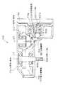
図1は、本発明の実施形態の例に係る動力伝達装置400を適用したギヤドモータ600の平面図、図4は正面図、図5は右側面図、図6は下面図をそれぞれ示したものである。
【0018】
ギヤドモータ600は、モータ500と、直交ギヤヘッド100と平行ギヤヘッド200とから構成される動力伝達装置400と、を備えている。
【0019】
モータ500と直交ギヤヘッド100は、取付面F1においてボルト504により連結・一体化されている。
【0020】
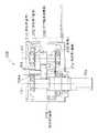
又、該直交ギヤヘッド100は、図2に示すように、自身のケーシング(以下、直交ギヤケーシングと称す。)102内に、入力される動力の回転方向を直交方向に変換する直交変換機構116と、該直交変換機構116の出力回転を増減速又は等速伝達する平行軸伝達機構118とを備えている。
【0021】
該直交変換機構116は、(この例では)ベベル歯車よりなる、中間第1歯車110及び中間第2歯車112を備えている。該中間第1歯車110には、その軸心L2に沿ってモータ軸502を挿入するための穴110bが設けられており、該穴110bの内側にはモータ軸502と中間第1歯車110を連結するためのヘルカルスプライン110aが形成されている。又、モータ軸502の先端にはヘリカルピニオン502aが形成されており、モータ軸502と中間第1歯車110は連結されると共に、一体回転可能となっている。
【0022】
又、平行軸伝達機構118は、軸線L1を中心として回転する中間出力軸108と、中間第3歯車114とを備えている。なお、中間出力軸108の軸心L1は、直交変換機構116の中間第1歯車110の軸心L2とは直交した関係(ねじれた関係)にあると共に、中間第2歯車112の軸心L3とは平行した関係にある。
【0023】
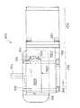
一方、平行ギヤヘッド200は、図3に示すように、自身のケーシング(以下、平行ギヤケーシングと称す。)202内に、直交ギヤヘッド100の出力を伝受可能な平行軸減速機構206を備えており、該直交ギヤヘッド100と連結が可能である。
【0024】
該平行軸減速機構206は、最終出力軸204と、第1軸208と、図示しない第2軸(以下、単に第2軸と称す。)とを備えている。
【0025】
第1軸208には、その軸心L4を中心として回転する大径の後段第1歯車210と、これより小径の後段第2歯車212とが設けられている。又、第2軸は、紙面奥側に図中L5相当位置をその軸心として、第1軸208と平行に配置されている。この第2軸には、前記後段第2歯車212と噛合し、該後段第2歯車212より大径の後段第3歯車214と、該後段第3歯車214より小径の図示しない後段第4歯車(以下、単に後段第4歯車と称す。)とが設けられている。更に、最終出力軸204には、前記後段第4歯車と噛合する後段第5歯車218が設けられている。
【0026】
前記中間出力軸108は、その先端部にモータ軸502と同一緒元のヘリカルピニオン108aが直接歯切りされており、平行ギヤヘッド200の平行ギヤケーシング202内に挿入され、第1軸208に設けられた後段第1歯車(ヘリカルギヤ)210と噛合し、平行軸減速機構206の初段ギヤセットを構成している。
【0027】
又、該平行ギヤヘッド200には、図6に示すように、自身を床などの外部に設置するための取付体300が直交ギヤヘッド100を貫通するボルト306により取り付けられている。
【0028】
前記直交ギヤヘッド100と平行ギヤヘッド200は、取付面F2において図示せぬボルトによって連結・一体化されている。取付面F2は前述したモータ500と直交ギヤヘッド100との取付面F1と同一の取合い寸法を有している。具体的にはモータ500と直交ギヤヘッド100との取付面F1と、直交ギヤヘッド100と平行ギヤヘッド200との取付面F2はいずれも略同形状の正方形とされ、それぞれの取付面F1、F2における図示せぬ取付ボルト孔の位置は、共にその正方形の四隅付近の同位置(取付面F1側もF2側も同じ辺の長さを有する正方形の頂点相当位置)に設けられている。各取付ボルト孔の孔径も取付面F1側とF2側とで同一である。なお、直交ギヤヘッド100の入出力軸線を含む直交ギヤケーシング102の断面の形状はL字形となっており、平行ギヤヘッド200は、取付体300を付設したままの状態で、直交ギヤケーシング102におけるL字形の両辺102xと102yで規定される空間に収まっている。
【0029】
前記取付体300は、平行ギヤヘッド200の出力軸204が突出しているケーシング面(以下、出力軸側ケーシング面と称す。)202aと、該ケーシング面202aと直角の関係にあるケーシング面202bを被さるように形成されたL字形の板状部材である。このL字形の取付体300を構成する2つの面300aと300bの間には補強用のリブ304が設けられている。又、この取付体300を図示しない固定部材に固定するための取付ボルト302は、平行ギヤヘッド200の出力軸側ケーシング面202aから見て、該平行ギヤヘッド200本体側に配置されている。
【0030】
前記直交ギヤヘッド100の入出力軸線を含む平面と平行の関係にある2つのL字形のケーシング面102a、102bには、取付ボルト302が2本分収納可能な大きさとした取付ボルト用逃げ104がそれぞれ設けられ、前記取付ボルト302との干渉を防ぐ形状になっている。更に、直交ギヤケーシング102には、前記取付体300のリブ304との干渉を防ぐためのリブ用逃げ106も設けられている。
【0031】
次に、ギヤドモータ600の作用について説明する。
【0032】
モータ500に通電すると、モータ軸502と連結した中間第1歯車110がその軸心L2を中心として回転する。
【0033】
そして、中間第1歯車110の回転により、該中間第1歯車110と直交・噛合する中間第2歯車112が軸線L2と直交する方向L3を軸心として回転する。その結果、モータ軸502より入力された動力の回転方向が90°転換される。
【0034】
又、中間第2歯車112の回転により、該中間第2歯車112と噛合する中間第3歯車114及び該中間第3歯車114が取付られた中間出力軸108は、軸線L3と平行関係にあるL1を軸心として回転する。そして、中間第2歯車112から伝達された回転が減速され、中間出力軸108に出力される。
【0035】
更に、中間出力軸108がその軸心L1を中心として回転すると、該中間出力軸108の先端部と噛合した後段第1歯車210と、該後段第1歯車210と同じ第1軸208に設けられた後段第2歯車212が、第1軸208の軸心L4を中心として回転する。
【0036】
その後、後段第2歯車212の回転と同時に、該後段第2歯車212と噛合する後段第3歯車214と、該後段第3歯車214と同じ第2軸に設けられた後段第4歯車が第2軸の軸心L5を中心として回転し、後段第2歯車212から伝達された回転が更に減速される。
【0037】
最終的に、後段第4歯車の回転により、該後段第4歯車と噛合する後段第5歯車218が回転すると共に、最終出力軸204が回転し、動力が出力される。
【0038】
直交ギヤヘッド100の入出力軸線を含む直交ギヤケーシング102の断面の形状をL字形にすると共に、平行軸減速機構を有する平行ギヤヘッド200を直交ギヤヘッド100と連結可能にしたため、平行ギヤヘッド200は、取付体300を有したままの状態で、直交ギヤケーシング102におけるL字形の両辺102xと102yで規定される空間に収納が可能で、全体として直交変換機構を有する動力伝達装置400として機能することができる。
【0039】
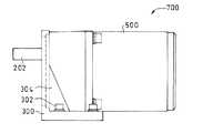
従って、平行ギヤヘッド200とその取付体300は、直交変換機構を有するギヤドモータ600の構成部品として使用できるばかりでなく、図7、図8に示すように、取付面F1とF2とが同一の取合寸法を有していることを利用して、モータ500を直接連結する(モータ軸502と後段第1歯車210を噛み合わせる)ことにより、平行軸減速機構を有するギヤドモータ700の構成部品としても使用可能であり、部品の共用化による開発コストの低減を図ることができる。なお、図7は本発明の実施の例に係る平行ギヤヘッド200及び取付体300を使用した平行軸減速機構を有するギヤドモータ700の平面図、図8はその正面図である。
【0040】
又、この取付体300を固定するための取付ボルト302は平行ギヤヘッド200の出力軸側ケーシング面202aから見て該平行ギヤヘッド200本体側に配置されているため、取付ボルト302が被駆動装置側に出っ張ることがなく、ギヤドモータ600を被駆動装置の近くに設置可能であると共に、省スペース化を実現することができる。なお、直交ギヤヘッド100の直交ギヤケーシング102には、取付ボルト用逃げ104が設けられているため、取付体300の取付ボルト302との干渉を防ぐことができる。
【0041】
前記取付体300は、平行ギヤヘッド200の出力軸側ケーシング面202aと、該ケーシング面202aと直角の関係にあるケーシング面202bを覆うように形成されたL字形の板状部材としたため、ギヤドモータ600の安定した取付けが可能となっている。しかも、取付体300を構成する2つの面300aと300bの間には補強用のリブ304が設けられているため、ギヤドモータ600の取付強度の向上を図ることができる。なお、直交ギヤヘッド100の直交ギヤケーシング102には、リブ用逃げ106が設けられているため、リブ304と干渉することがない。
【0042】
直交ギヤヘッド100の入出力軸線を含む平面と平行の関係にある2つのL字形のケーシング面102a、102bには、取付ボルト用逃げ104をそれぞれ設け、また、平行ギヤヘッド200を、直交ギヤヘッド100の中間出力軸108を中心として、該中間出力軸108の円周方向Rに回転して取付けできるようにしている。従って、図9中の(A)に示すように、直交ギヤヘッド100のケーシング面102aを上面に、102bを設置面(底面)にすることができるのみならず、図9中の(B)に示すように、ケーシング面102bを上面に、102aを設置面(底面)にすることができ、ギヤドモータ600の使用用途に応じた取付けが可能となる。更に、モータ500、直交ギヤヘッド100、平行ギヤヘッド200及び取付体300は、他にも図10の模式図に示すような様々な組合せが可能で、ギヤドモータ600を設置場所に応じて配置することが可能となっている。
【0043】
本実施形態においては、平行ギヤヘッド200を直交ギヤヘッド100のL字の空間にほぼ一杯に収容される大きさで形成し、その上で直交ギヤケーシング(直交ギヤヘッド100のケーシング)102に取付ボルト用逃げ104やリブ用逃げ106、即ち「凹部」を形成している。これは、直交ギヤケーシング102の直交減速機構116が存在する部分は、該直交ギヤケーシング102の中央付近の一部のみであることに着目して歯車のない空間を利用するようにしたものである。即ち、この逃げ104、106の存在によりギヤドモータ600全体の大きさを大きくすることなく、且つ、取付ボルト302をギヤドモータ600の本体から突出させることなく、ギヤドモータ600を床などの外部に固定することが可能となっている。
【0044】
なお、上記実施形態においては、取付体300をL字形としたが、本発明はこれに限定されるものではなく、例えば、取付体300を板状部材とすると共に、該取付体300を前記平行ギヤヘッド200の出力軸線L6と平行の関係にある4つのケーシング面202b、202c、202d、202eのいずれかに取付け、該取付体によりギヤドモータ600を設置してもよい。
【0045】
又、取付ボルト用逃げ104を取付ボルト302を2本分収納可能な大きさとしたが、本発明はこれに限定されるものではない。
【0046】
【発明の効果】
本発明によれば、部品の共用化による開発コストの低減や省スペース化を実現することのできる動力伝達装置を提供することができる。
【図面の簡単な説明】
【図1】本発明の実施形態に係る動力伝達装置を適用したギヤドモータの平面図
【図2】図1における直交ギヤヘッドの断面図
【図3】図1における平行ギヤヘッドのIII−III線に沿う断面図
【図4】図1におけるギヤドモータの正面図
【図5】図1におけるギヤドモータの右側面図
【図6】図1におけるギヤドモータの下面図
【図7】平行軸減速機構を有するギヤドモータの平面図
【図8】図7におけるギヤドモータの正面図
【図9】図1におけるギヤドモータの設置例を示した図
【図10】図1におけるギヤドモータの構成例を示した模式図
【符号の説明】
100…直交ギヤヘッド
102…直交ギヤケーシング
104…取付ボルト用逃げ
106…リブ用逃げ
108…中間出力軸
116…直交変換機構
118…平行軸伝達機構
200…平行ギヤヘッド
202…平行ギヤケーシング
204…最終出力軸
206…平行軸減速機構
208…第1軸
300…取付体
302…取付ボルト
304…リブ
400…動力伝達装置
500…モータ
502…モータ軸
504…ボルト
600…ギヤドモータ
700…平行軸ギヤドモータ[0001]
BACKGROUND OF THE INVENTION
The present invention relates to a power transmission device suitable for application to, for example, a geared motor used in a drive system such as a conveyor of a physical distribution system.
[0002]
[Prior art]
2. Description of the Related Art Conventionally, there is known a power transmission device having an orthogonal conversion mechanism that can convert rotation of input power in an orthogonal direction. In the power transmission device having this orthogonal transformation mechanism, the axes of the input / output shafts are orthogonal to each other, and the device can be made compact in the axial direction of the output shaft. The apparatus can be installed.
[0003]
Moreover, when installing such a power transmission device, it is common to install it outside the floor or the like via a mounting body for mounting the device.
[0004]
[Problems to be solved by the invention]
However, many of such attachments are molded integrally with the apparatus main body, and must be individually designed and manufactured according to the type and size of the apparatus.
[0005]
In addition, since the mounting body is often disposed at a position protruding from the device, the driven device cannot be disposed in the vicinity of the device, and the space characteristic of the power transmission device having the orthogonal transformation mechanism is limited. There was a problem that it was not possible to make full use of the merit that it was possible to install even in different locations.
[0006]
The present invention has been made to solve such a problem, and an object of the present invention is to provide a power transmission device capable of reducing development cost and space saving by sharing parts. To do.
[0007]
[Means for Solving the Problems]
The present invention provides a cross section including an input / output axis of the orthogonal transformation mechanism, an orthogonal transformation mechanism that transforms the rotational direction of input power into an orthogonal direction, and a parallel shaft transmission mechanism that transmits output rotation of the orthogonal transformation mechanism. An orthogonal gear head housed in an L-shaped casing and a parallel shaft reduction mechanism capable of transmitting the output of the parallel axis transmission mechanism are provided in a space defined by both sides of the L-shape of the casing of the orthogonal gear head. The parallel gear head accommodated in the casing that accommodates most of the parallel gear head can be connected and integrated while the mounting body for installing the power transmission device outside is attached to the casing of the parallel gear head. Thus, the above problem is solved.
[0008]
According to the present invention, since the cross-sectional shape of the casing including the input / output axis of the orthogonal gear head is L-shaped and the parallel gear head having the parallel shaft reduction mechanism can be connected to the orthogonal gear head, the parallel gear head is connected to the parallel gear head. Can be housed in a space defined by both L-shaped sides of the casing of the orthogonal gear head with the attachment body for installing the attachment, and can function as a power transmission device having an orthogonal conversion mechanism as a whole. it can.
[0009]
The parallel gear head houses the parallel shaft reduction mechanism in its own casing, and the mounting body is attached to the side of the parallel gear head, so that it functions as a power transmission device having a parallel shaft reduction mechanism by itself. It can be attached independently to the outside such as a floor. Accordingly, the parallel gear head and its mounting body can be used not only as a component of a power transmission device having an orthogonal transformation mechanism, but also as a component of a power transmission device having only a parallel shaft reduction mechanism if necessary. Development costs can be reduced by sharing these.
[0010]
In addition, a mounting bolt for fixing the mounting body to the outside is disposed on the parallel gear head body side when viewed from the casing surface from which the output shaft of the parallel gear head protrudes, and the mounting bolt is mounted on the casing of the orthogonal gear head. If there is a relief for the mounting bolt to prevent interference with the power transmission device, the mounting bolt of the power transmission device will not protrude to the driven device side, so the power transmission device can be installed near the driven device, saving space Can be realized.
[0011]
Furthermore, if the mounting bolt relief is provided on each of two L-shaped casing surfaces in parallel with the plane including the input / output axis of the orthogonal gear head, one of the two L-shaped casing surfaces is installed. Since the device can be formed into a plane, the device can be installed on both sides of the driven device, and the power transmission device can be mounted according to the usage condition.
[0012]
Further, the mounting body is an L-shaped plate formed so as to cover one of the casing surface from which the output shaft of the parallel gear head protrudes and the four casing surfaces perpendicular to the casing surface. If it is a member, attachment according to a use application becomes possible, and it becomes possible to improve attachment strength of a device by making it L-shaped.
[0013]
Further, if a rib is provided between the two surfaces constituting the L-shaped attachment body and a rib relief for preventing interference with the rib is provided in the casing of the orthogonal gear head, the size of the entire apparatus can be obtained. It is possible to further improve the mounting strength of the apparatus without increasing the size.
[0014]
The attachment body may be a plate-like member, and the attachment body may be attachable to any one of four casing surfaces that are parallel to the parallel gear head.
[0015]
Further, when the parallel gear head is configured to be mounted by rotating in the circumferential direction of the output shaft around the output shaft of the orthogonal gear head, the position of the output shaft of the parallel gear head is set to the output of the orthogonal gear head. It becomes possible to change the position 360 degrees around the axis, so that it can be mounted according to the intended use, and can easily cope with a change in the mounting position.
[0016]
DETAILED DESCRIPTION OF THE INVENTION
Embodiments of the present invention will be described below with reference to the drawings.
[0017]
1 is a plan view of a geared
[0018]
The geared
[0019]
The
[0020]
Further, as shown in FIG. 2, the
[0021]
The orthogonal transformation mechanism 116 includes an intermediate
[0022]
The parallel
[0023]
On the other hand, as shown in FIG. 3, the
[0024]
The parallel shaft speed reduction mechanism 206 includes a
[0025]
The
[0026]
The
[0027]
Further, as shown in FIG. 6, the
[0028]
The
[0029]
The mounting
[0030]
Two L-shaped
[0031]
Next, the operation of the geared
[0032]
When the
[0033]
Then, due to the rotation of the intermediate
[0034]
Further, the intermediate third gear 114 meshed with the intermediate second gear 112 and the
[0035]
Further, when the
[0036]
Thereafter, simultaneously with the rotation of the second-stage second gear 212, the second-stage third gear 214 that meshes with the second-stage second gear 212 and the second-stage fourth gear provided on the same second shaft as the second-stage third gear 214 are The rotation rotates around the shaft center L5 of the shaft, and the rotation transmitted from the second-stage second gear 212 is further decelerated.
[0037]
Finally, the rotation of the rear fourth gear rotates the rear
[0038]
Since the shape of the cross section of the
[0039]
Therefore, the
[0040]
Further, since the mounting
[0041]
Since the
[0042]
Two L-shaped casing surfaces 102 a and 102 b that are parallel to the plane including the input / output axis of the
[0043]
In this embodiment, the
[0044]
In the above embodiment, the
[0045]
Further, although the mounting
[0046]
【The invention's effect】
ADVANTAGE OF THE INVENTION According to this invention, the power transmission device which can implement | achieve reduction of the development cost and space saving by sharing of components can be provided.
[Brief description of the drawings]
1 is a plan view of a geared motor to which a power transmission device according to an embodiment of the present invention is applied. FIG. 2 is a cross-sectional view of an orthogonal gear head in FIG. 1. FIG. 3 is a cross section of a parallel gear head in FIG. Fig. 4 is a front view of the geared motor in Fig. 1. Fig. 5 is a right side view of the geared motor in Fig. 1. Fig. 6 is a bottom view of the geared motor in Fig. 1. Fig. 7 is a plan view of a geared motor having a parallel shaft reduction mechanism. 8 is a front view of the geared motor in FIG. 7. FIG. 9 is a diagram showing an installation example of the geared motor in FIG. 1. FIG. 10 is a schematic diagram showing a configuration example of the geared motor in FIG.
DESCRIPTION OF
Claims (7)
Translated fromJapanese前記平行軸伝達機構の出力を伝受可能な平行軸減速機構を、前記直交ギヤヘッドのケーシングの前記L字形の両辺で規定される空間にその大部分が収まるケーシング内に収容した平行ギヤヘッドとを、
該平行ギヤヘッドのケーシングに当該動力伝達装置を外部に設置するための取付体を付設したままの状態で、連結・一体化可能とした
ことを特徴とする動力伝達装置。An orthogonal transformation mechanism that transforms the rotational direction of input power into an orthogonal direction and a parallel shaft transmission mechanism that transmits output rotation of the orthogonal transformation mechanism, and a cross-sectional shape including an input / output axis of the orthogonal transformation mechanism is L-shaped An orthogonal gearhead housed in a casing,
A parallel gear reduction mechanism capable of transmitting and receiving the output of the parallel shaft transmission mechanism, and a parallel gear head housed in a casing, most of which is contained in a space defined by both sides of the L-shape of the casing of the orthogonal gear head,
A power transmission device characterized in that it can be connected and integrated with a mounting body for installing the power transmission device externally attached to a casing of the parallel gear head.
前記取付体を外部に固定するための取付ボルトを、前記平行ギヤヘッドの出力軸が突出しているケーシング面から見て該平行ギヤヘッド本体側に配置すると共に、
前記直交ギヤヘッドのケーシングに前記取付ボルトとの干渉を防ぐための取付ボルト用逃げを設けた
ことを特徴とする動力伝達装置。In claim 1,
A mounting bolt for fixing the mounting body to the outside is disposed on the parallel gear head main body side when viewed from the casing surface from which the output shaft of the parallel gear head projects,
A power transmission device comprising a mounting bolt relief for preventing interference with the mounting bolt in the casing of the orthogonal gear head.
前記取付ボルト用逃げを、前記直交ギヤヘッドの入出力軸線を含む平面と平行の関係にある2つのL字形のケーシング面にそれぞれ設けた
ことを特徴とする動力伝達装置。In claim 2,
The power transmission device, wherein the mounting bolt reliefs are respectively provided on two L-shaped casing surfaces that are parallel to a plane including the input / output axis of the orthogonal gear head.
前記取付体を、前記平行ギヤヘッドの出力軸が突出しているケーシング面と、該ケーシング面と直角の関係にある4つのケーシング面のいずかを覆うように形成されたL字形の板状部材とした
ことを特徴とする動力伝達装置。In any one of Claims 1 thru | or 3,
An L-shaped plate-like member formed to cover the attachment body so as to cover a casing surface from which the output shaft of the parallel gear head protrudes, and four casing surfaces perpendicular to the casing surface; A power transmission device characterized by that.
前記L字形の取付体を構成する2つの面の間にリブを設けると共に、
前記直交ギヤヘッドのケーシングに前記リブとの干渉を防ぐためのリブ用逃げを設けた
ことを特徴とする動力伝達装置。In claim 4,
A rib is provided between two surfaces constituting the L-shaped attachment body, and
A power transmission device, wherein a rib relief for preventing interference with the rib is provided in a casing of the orthogonal gear head.
前記取付体を板状部材とすると共に、該取付体を、前記平行ギヤヘッドの出力軸線と平行の関係にある4つのケーシング面のいずれかに取付可能とした
ことを特徴とする動力伝達装置。In any one of Claims 1 thru | or 3,
A power transmission device characterized in that the attachment body is a plate-like member, and the attachment body can be attached to any one of four casing surfaces in parallel relation to the output axis of the parallel gear head.
前記平行ギヤヘッドを、前記直交ギヤヘッドの出力軸を中心として、該出力軸の円周方向に回転して取付可能とした
ことを特徴とする動力伝達装置。In any one of Claims 1 thru | or 6.
A power transmission device characterized in that the parallel gear head can be attached by rotating around the output shaft of the orthogonal gear head in the circumferential direction of the output shaft.
Priority Applications (5)
| Application Number | Priority Date | Filing Date | Title |
|---|---|---|---|
| JP2002088678AJP3806842B2 (en) | 2002-03-27 | 2002-03-27 | Power transmission device |
| TW092104092ATWI223036B (en) | 2002-03-22 | 2003-02-26 | Speed reduction device for gear reduction motor, gear reduction motor and products thereof |
| KR10-2003-0017916AKR20030076449A (en) | 2002-03-22 | 2003-03-21 | A reducer for geared motor, a geared motor, and product group thereof |
| US10/393,362US7370549B2 (en) | 2002-03-22 | 2003-03-21 | Reduction gear for geared motor, geared motor, and product group thereof |
| CNB031073646ACN100387865C (en) | 2002-03-22 | 2003-03-24 | Reducers for geared motors, geared motors and their product series |
Applications Claiming Priority (1)
| Application Number | Priority Date | Filing Date | Title |
|---|---|---|---|
| JP2002088678AJP3806842B2 (en) | 2002-03-27 | 2002-03-27 | Power transmission device |
Publications (2)
| Publication Number | Publication Date |
|---|---|
| JP2003278842A JP2003278842A (en) | 2003-10-02 |
| JP3806842B2true JP3806842B2 (en) | 2006-08-09 |
Family
ID=29234472
Family Applications (1)
| Application Number | Title | Priority Date | Filing Date |
|---|---|---|---|
| JP2002088678AExpired - Fee RelatedJP3806842B2 (en) | 2002-03-22 | 2002-03-27 | Power transmission device |
Country Status (1)
| Country | Link |
|---|---|
| JP (1) | JP3806842B2 (en) |
Families Citing this family (2)
| Publication number | Priority date | Publication date | Assignee | Title |
|---|---|---|---|---|
| JP5869356B2 (en)* | 2012-02-02 | 2016-02-24 | ヤンマー株式会社 | Work vehicle |
| CN107795640A (en)* | 2017-11-17 | 2018-03-13 | 江阴齿轮箱制造有限公司 | H/B Series Gear tank module structures |
- 2002
- 2002-03-27JPJP2002088678Apatent/JP3806842B2/ennot_activeExpired - Fee Related
Also Published As
| Publication number | Publication date |
|---|---|
| JP2003278842A (en) | 2003-10-02 |
Similar Documents
| Publication | Publication Date | Title |
|---|---|---|
| TW201433057A (en) | Motor and rotating mechanism and electronic device using same | |
| CN108291609B (en) | Speed reducer | |
| KR20030076449A (en) | A reducer for geared motor, a geared motor, and product group thereof | |
| JP2004197921A (en) | Hypoid reduction gear unit and its series | |
| JP3806842B2 (en) | Power transmission device | |
| JP3889300B2 (en) | Reducer for geared motor, geared motor and its series | |
| JP2002235832A (en) | Differential gear with reduction gear | |
| JP2018105373A (en) | Speed reducer, articulation device and robot arm structure | |
| TW200823125A (en) | Gear power transmission device | |
| KR200441753Y1 (en) | Geared Motor with Encoder | |
| CN222003510U (en) | Robot transmission mechanism and robot | |
| JP4847744B2 (en) | Orthogonal axis reducer with motor, orthogonal axis reducer, and joint structure of robot | |
| JP2010045890A (en) | Geared outer-rotor brushless motor | |
| CN100394069C (en) | Orthogonal Power Transfer Device | |
| JPH10299840A (en) | Orthogonal shaft gear reducer | |
| JP4919741B2 (en) | Decelerator | |
| CN107701667B (en) | Composite speed reducer | |
| US6716134B1 (en) | Step-up reduction gearing | |
| CN220523189U (en) | Speed reducer | |
| CN100359212C (en) | Noise-reducing gear | |
| CN215990475U (en) | Motor assembly | |
| JP2013167278A (en) | Reduction gear | |
| CN220378857U (en) | Double-input planetary prepositive speed reducer | |
| CN215928328U (en) | Multifunctional speed reducer and all-in-one machine | |
| CN211648941U (en) | Miniature upset motor |
Legal Events
| Date | Code | Title | Description |
|---|---|---|---|
| A621 | Written request for application examination | Free format text:JAPANESE INTERMEDIATE CODE: A621 Effective date:20040510 | |
| A977 | Report on retrieval | Free format text:JAPANESE INTERMEDIATE CODE: A971007 Effective date:20060201 | |
| TRDD | Decision of grant or rejection written | ||
| A01 | Written decision to grant a patent or to grant a registration (utility model) | Free format text:JAPANESE INTERMEDIATE CODE: A01 Effective date:20060425 | |
| A61 | First payment of annual fees (during grant procedure) | Free format text:JAPANESE INTERMEDIATE CODE: A61 Effective date:20060428 | |
| R150 | Certificate of patent or registration of utility model | Free format text:JAPANESE INTERMEDIATE CODE: R150 Ref document number:3806842 Country of ref document:JP Free format text:JAPANESE INTERMEDIATE CODE: R150 | |
| S531 | Written request for registration of change of domicile | Free format text:JAPANESE INTERMEDIATE CODE: R313531 | |
| FPAY | Renewal fee payment (event date is renewal date of database) | Free format text:PAYMENT UNTIL: 20090526 Year of fee payment:3 | |
| R350 | Written notification of registration of transfer | Free format text:JAPANESE INTERMEDIATE CODE: R350 | |
| FPAY | Renewal fee payment (event date is renewal date of database) | Free format text:PAYMENT UNTIL: 20100526 Year of fee payment:4 | |
| FPAY | Renewal fee payment (event date is renewal date of database) | Free format text:PAYMENT UNTIL: 20110526 Year of fee payment:5 | |
| FPAY | Renewal fee payment (event date is renewal date of database) | Free format text:PAYMENT UNTIL: 20120526 Year of fee payment:6 | |
| FPAY | Renewal fee payment (event date is renewal date of database) | Free format text:PAYMENT UNTIL: 20120526 Year of fee payment:6 | |
| FPAY | Renewal fee payment (event date is renewal date of database) | Free format text:PAYMENT UNTIL: 20130526 Year of fee payment:7 | |
| FPAY | Renewal fee payment (event date is renewal date of database) | Free format text:PAYMENT UNTIL: 20130526 Year of fee payment:7 | |
| S802 | Written request for registration of partial abandonment of right | Free format text:JAPANESE INTERMEDIATE CODE: R311802 | |
| R350 | Written notification of registration of transfer | Free format text:JAPANESE INTERMEDIATE CODE: R350 | |
| LAPS | Cancellation because of no payment of annual fees |