JP3805846B2 - Orthodontic bracket and curing light assembly - Google Patents
Orthodontic bracket and curing light assemblyDownload PDFInfo
- Publication number
- JP3805846B2 JP3805846B2JP33422696AJP33422696AJP3805846B2JP 3805846 B2JP3805846 B2JP 3805846B2JP 33422696 AJP33422696 AJP 33422696AJP 33422696 AJP33422696 AJP 33422696AJP 3805846 B2JP3805846 B2JP 3805846B2
- Authority
- JP
- Japan
- Prior art keywords
- bracket
- base
- adhesive
- housing
- light
- Prior art date
- Legal status (The legal status is an assumption and is not a legal conclusion. Google has not performed a legal analysis and makes no representation as to the accuracy of the status listed.)
- Expired - Fee Related
Links
- 239000000853adhesiveSubstances0.000claimsdescription79
- 230000001070adhesive effectEffects0.000claimsdescription79
- 239000003795chemical substances by applicationSubstances0.000claimsdescription2
- 230000008878couplingEffects0.000claims2
- 238000010168coupling processMethods0.000claims2
- 238000005859coupling reactionMethods0.000claims2
- 238000001723curingMethods0.000description39
- 238000000034methodMethods0.000description13
- 239000007787solidSubstances0.000description10
- 239000000463materialSubstances0.000description6
- 239000002184metalSubstances0.000description6
- 230000002093peripheral effectEffects0.000description6
- 239000011248coating agentSubstances0.000description5
- 238000000576coating methodMethods0.000description5
- 230000013011matingEffects0.000description5
- 239000000835fiberSubstances0.000description4
- 238000003825pressingMethods0.000description4
- 238000009434installationMethods0.000description3
- 239000013307optical fiberSubstances0.000description3
- 244000261422Lysimachia clethroidesSpecies0.000description2
- 238000005253claddingMethods0.000description2
- 239000003479dental cementSubstances0.000description2
- 239000011888foilSubstances0.000description2
- 239000012634fragmentSubstances0.000description2
- 210000004283incisorAnatomy0.000description2
- 238000005304joiningMethods0.000description2
- 229920003023plasticPolymers0.000description2
- 238000012216screeningMethods0.000description2
- 239000004065semiconductorSubstances0.000description2
- 239000012798spherical particleSubstances0.000description2
- 230000002269spontaneous effectEffects0.000description2
- OAICVXFJPJFONN-UHFFFAOYSA-NPhosphorusChemical compound[P]OAICVXFJPJFONN-UHFFFAOYSA-N0.000description1
- 238000007792additionMethods0.000description1
- 230000008901benefitEffects0.000description1
- 239000000919ceramicSubstances0.000description1
- 229910010293ceramic materialInorganic materials0.000description1
- 230000008859changeEffects0.000description1
- 238000004140cleaningMethods0.000description1
- 230000000295complement effectEffects0.000description1
- 238000013461designMethods0.000description1
- 238000006073displacement reactionMethods0.000description1
- 230000005684electric fieldEffects0.000description1
- 230000005670electromagnetic radiationEffects0.000description1
- 210000004195gingivaAnatomy0.000description1
- 210000004013groinAnatomy0.000description1
- 235000021059hard foodNutrition0.000description1
- 230000006872improvementEffects0.000description1
- 230000014759maintenance of locationEffects0.000description1
- 239000007769metal materialSubstances0.000description1
- 230000005012migrationEffects0.000description1
- 238000013508migrationMethods0.000description1
- 238000012986modificationMethods0.000description1
- 230000004048modificationEffects0.000description1
- 238000000016photochemical curingMethods0.000description1
- 229920000642polymerPolymers0.000description1
- 230000008569processEffects0.000description1
- 230000006798recombinationEffects0.000description1
- 238000005215recombinationMethods0.000description1
- 230000000717retained effectEffects0.000description1
- 229920005573silicon-containing polymerPolymers0.000description1
- 229910001220stainless steelInorganic materials0.000description1
- 239000010935stainless steelSubstances0.000description1
- 239000000126substanceSubstances0.000description1
- 230000000007visual effectEffects0.000description1
- 239000011800void materialSubstances0.000description1
Images


Classifications
- A—HUMAN NECESSITIES
- A61—MEDICAL OR VETERINARY SCIENCE; HYGIENE
- A61C—DENTISTRY; APPARATUS OR METHODS FOR ORAL OR DENTAL HYGIENE
- A61C19/00—Dental auxiliary appliances
- A61C19/003—Apparatus for curing resins by radiation
- A61C19/004—Hand-held apparatus, e.g. guns
- A—HUMAN NECESSITIES
- A61—MEDICAL OR VETERINARY SCIENCE; HYGIENE
- A61C—DENTISTRY; APPARATUS OR METHODS FOR ORAL OR DENTAL HYGIENE
- A61C7/00—Orthodontics, i.e. obtaining or maintaining the desired position of teeth, e.g. by straightening, evening, regulating, separating, or by correcting malocclusions
- A61C7/12—Brackets; Arch wires; Combinations thereof; Accessories therefor
- A61C7/14—Brackets; Fixing brackets to teeth
- A61C7/16—Brackets; Fixing brackets to teeth specially adapted to be cemented to teeth
- A—HUMAN NECESSITIES
- A61—MEDICAL OR VETERINARY SCIENCE; HYGIENE
- A61C—DENTISTRY; APPARATUS OR METHODS FOR ORAL OR DENTAL HYGIENE
- A61C7/00—Orthodontics, i.e. obtaining or maintaining the desired position of teeth, e.g. by straightening, evening, regulating, separating, or by correcting malocclusions
- A61C7/12—Brackets; Arch wires; Combinations thereof; Accessories therefor
- A61C7/14—Brackets; Fixing brackets to teeth
- A61C7/146—Positioning or placement of brackets; Tools therefor
Landscapes
- Health & Medical Sciences (AREA)
- Oral & Maxillofacial Surgery (AREA)
- Dentistry (AREA)
- Epidemiology (AREA)
- Life Sciences & Earth Sciences (AREA)
- Animal Behavior & Ethology (AREA)
- General Health & Medical Sciences (AREA)
- Public Health (AREA)
- Veterinary Medicine (AREA)
- Dental Tools And Instruments Or Auxiliary Dental Instruments (AREA)
Description
Translated fromJapanese【0001】
本発明は、改良された歯科矯正ブラケットおよび光硬化アセンブリーに関し、それらは、一緒になって、ブラケットと歯との間の結合強度、特にブラケット基底部の中央部分の直下での結合強度を高める。
【0002】
歯科矯正処置は、正しい噛み合わせのために望ましい位置への歯の移動を含む。処置の間、ブラケットと呼ばれている小さいスロット状に開いた歯科矯正器具は歯に連結され、そしてアーチワイヤーは各ブラケットのスロットに入れられる。アーチワイヤーは、歯が歯科矯正学上正しい位置に移動するのを導くためのトラックを形成する。
【0003】
多くの市販の歯科矯正ブラケットは、歯科矯正結合用接着剤の手段により患者の歯の表面に直接的に結合されるようになっている。CONCISE ブランドの接着剤(3M Unitek) のような特定の種類の接着剤は、最初は2 種の別個の成分として供給され、それらが混合されたときに、自己硬化性になる。このような2 成分接着剤は、しかしながら、限られた「可使時間」しかなく、その間にのみ、歯科矯正医はブラケットの基底部に接着剤を付け、ブラケットを歯の上に付け、そして接着剤が硬化し始める前にブラケットをある所望の位置に移動することができる。TRANSBOND ブランドの接着剤( これも3M Unitek)のような他の接着剤は、光硬化性であり、そして光源が接着剤に向けられたときに硬化し始める。光硬化性の接着剤は、「可使時間」の長さが必要に応じて選べるので、多くの歯科矯正医に好まれている。使用時に、ブラケットは患者の歯の上に注意深く置かれ、そして歯科矯正医がブラケットに位置に満足するまで所望により移動されうる。有利には、光源が接着剤に向けられるまで接着剤は硬化しない。
【0004】
ブラケットと歯の間の強度を上げるための多くの試みが長年にわたってなされてきた。幾つかのブラケットは、例えば、ざらざらにし、刻みを付け、または、くぼみを付けた外側基底部表面を有し、他のブラケットは少なくとも1 層の不規則な形状のフラグメントまたは球状粒子の層を含む基底部表面を含む。このような基底部表面は接着剤との接触のために使用されうる高い表面積を提供し、それにより、ブラケットと歯との間の結合強度を高める。
【0005】
あるブラケットは、添窩領域(undercut regions)を提供する基底部を有する。基底部内の添窩は、接着剤が、硬化したときに、ブラケットとの機械的なインターロックを形成することを可能にする。例えば、上記の不規則な形状のフラグメントまたは球状粒子は添窩領域を提供しうる。別の例として、幾つかのブラケットの基底部は硬化した接着剤中に埋め込まれたときに機械的なインターロックを提供する微細メッシュ金属「スクリーン」またはパッドを有する。U.S. Design Patent第290,040 号に記載されているような他のブラケットは、硬化した接着剤との機械的なインターロックを提供する一連の添窩溝を有する。米国特許第4,094,068 号および第5,435,720 号は、接着剤が流れ込み、そして歯に接したブラケットの保持を改良するように働く大きなヘッドを生じる周囲孔またはノッチを有する基底部を有するブラケットを記載している。
【0006】
しかし、処置の間にブラケットの自発的な意図しない脱落を避けるために、特定の種類のブラケットと患者の歯との間の結合の強度を改良することが当業界において継続的に必要である。ある場合には、患者が比較的に硬い食品を噛んだきのような、比較的に大きな力を受けたときに、結合は、歯にブラケットを保持するために十分な強度を有しない。別の場合には、アーチワイヤー、歯科矯正補助具またはブラケットに連結した取り付け具によってかかる力からブラケットは脱結合しうる。歯科矯正ブラケットの早期脱結合は、歯科矯正医および患者の両者にとって厄介であり、最も良好には避けたいものである。それは、患者は、通常、処置を再開するために脱落したブラケットを再び取り付けるかまたは新規のブラケットに取り替えるために歯科矯正医に戻らなければならないからである。
【0007】
更に、光硬化性結合接着剤が金属ブラケットとともに使用されるときに、最近の努力は結合強度を上げることに向けられている。光硬化性接着剤が半透明なまたは透明なプラスティック、セラミックまたは他の材料から作られたブラケットとともに使用されるときに、硬化装置からの光は、通常、ブラケットを通して通過し、そしてブラケット基底部と歯との間の接着剤の全てではないにしても殆どを硬化する。しかし、金属ブラケットは、ブラケット基底部の中央部分への光の通過を実質的にブロックし、その結果、中央部分に付近の接着剤は未硬化のままである。しばしば、硬化光は、金属ブラケットの基底部の2 以上の縁に沿って接着剤に向けられるが、このようなことを行っても、ブラケットが比較的に大きな力を受けるときに、ブラケットの意図しない脱結合を妨げるために必要な程度に十分な量の接着剤を硬化しえない。
【0008】
歯科矯正ブラケットの結合手順において時々遭遇する別の困難性は、ブラッケトの装着後で且つ接着剤の硬化前の過剰な接着剤の除去に関する。多くの結合手順において、ブラケットは所定の位置に注意深く配置され、そしてその後、接着剤にブラケットをしっかりと付けるために圧力が加えられる。しばしば、歯科矯正医は、ブラケット基底部の全体表面が接着剤と接触し、そして接着剤が存在しないところでブラケットと歯との間に空気泡または空隙ができないように、据え付ける前に過剰の量の接着剤を塗布することを選択するであろう。据え付けの間に、ブラケット基底部の直下部からブラケット基底部の周囲に隣接した患者の歯の領域に過剰の接着剤は押し出される。その後、歯科深診器具または他の器具を使用して、歯の表面から押し出された接着剤を取り出し、そして除去する。
【0009】
しかし、過剰な接着剤の除去の間に、深診器具はブラケットとぶつかり、そしてその意図された位置から若干移動しうる。このような場合、しばしば、ブラケットを単純に元の位置に戻すことは推奨されない。というのは、満足される結合のためには不十分な接着剤がブラケットの下に残っており、そして空隙が生じうるからである。代わりに、通常、ブラケットおよび接着剤を歯から除去し、ブラケット基底部に追加の接着剤を付け、そしてブラケットを歯の上に再配置し、据え付け、そして新たに押し出された接着剤を除去することが推奨され、手順は、結局、幾分時間がかかる。
【0010】
本発明は、従来のブラケット、光硬化性ユニットおよび手順に関する上記の問題を克服するものであり、ブラケットの中央部分と患者の歯との間で直接的に接着剤の部分を結合するための改良された方法および装置を提供することによるものである。所望ならば、明細書中に記載されるこの方法および装置は、ブラケットの据え付けの間にブラケット基底部の周囲縁から押し出された接着剤が硬化することなく、歯にブラケットを一時的に固定するために有利に使用されうる。一旦、このように、ブラケットが歯に一時的に固定されると、過剰の押し出された接着剤は歯科深診器具または他の器具により容易に除去されるが、深診器具が意図せずにぶつかったときでも接着剤の硬化した部分はブラケットを移動することを妨げるであろう。押し出された接着剤の除去に続いて、歯科矯正処置のために有用な値まで接着剤の結合強度を上げるために、ブラケット基底部の周囲縁と歯との間の接着剤の部分を硬化するために硬化ユニットを使用することができる。
【0011】
より詳細には、本発明は、一態様において、歯科矯正ブラケットおよび硬化光アセンブリーの組み合わせに関する。この組み合わせは、歯への直接結合のための外側表面を有する基底部を有する歯科矯正ブラケットを含み、ここで、この基底部は少なくとも1個の開口部を有する中央部分を含む。ブラケットは、また、外側表面から離れる方向に向かって基底部から延びているボディーを含む。ブラケットは、また、ボディーから外側に向かって延びている少なくとも1個のタイウィング(tiewing)を含み、且つ、アーチワイヤーを受け入れるためのタイウィングに隣接したスロットを含む。ボディーは、基底部の開口部に位置合わせされた通路を有する中央セクションを含む。この組み合わせは、また、ブラケットボディーの通路において受け入れるために十分な大きさの外側末端部分を有するハウジングを有する硬化光アセンブリーをも含む。硬化光アセンブリーは、ハウジングの外側末端部分が通路において光を受けるときに、ブラケットの中央部分と接触している結合接着剤を硬化するために外側末端部分から光を発するハウジングに連結された光源を含む。
【0012】
本発明の別の態様は、歯に直接結合するための外側表面を有する基底部を含む歯科矯正ブラケットに関し、ここで、基底部は、少なくとも1個の開口部を有する中央部分を含む。ブラケットは、また、外側表面から離れる方向に向かって基底部から延びているボディーを含む。ボディーは、通路を有する中央部分を含む。少なくとも1個のタイウィングはボディーから外側に向かって延びており、そしてスロットはアーチワイヤーを受け入れるためのタイウィングに隣接している。ボディーは通路を含み、それは基底部の中央部分と接触している光硬化性結合接着剤を硬化するための光の光源を受けるための基底部の開口部と位置合わせされている。
【0013】
本発明は、また、外側末端部分およびハウジングに連結された光源を含む歯科矯正用硬化光アセンブリーに関する。光源は、外側末端部分から離れる方向に光を発するように操作可能である。アセンブリーは、また、外側末端部分を歯科矯正ブラケットに取り外し可能に連結するためのカップラーをも含む。
【0014】
本発明は、ステンレススチールまたは他の材料のような不透明な材料から作られたブラケットで使用されるときに特に有利である。というのは、ブラケットの通路はブラケット基底部の中央部分の下の接着剤に光を到達させることができ、さもなければ実質的に硬化しなかったであろうからである。ブラケットと歯の間の結合強度は、結果的に高くなり、そして処置の間に、意図しない、自発的なブラケットの脱結合が起こる可能性を有意に低下させる。
【0015】
本発明の更なる詳細は、特許請求の範囲の特徴において規定される。
【0016】
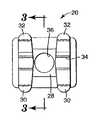
本発明の原理により製造された歯科矯正ブラケットは、図1〜4および図6〜11の数値20により広く指定される。図1〜4を最初に参照し、ブラケット20は、特定の歯に直接的に結合されるように調整されている特定の凹型形状の外側表面を有する基底部22を含む。好ましくは、凹型形状は歯の凸型外側表面と適合する複雑な形状を有する。
【0017】
基底部22は円状開口部24を有する中央部分を含む(図2〜3)。更に、基底部22は、一連の直立ペグ26を含み、それは開口部24を包囲している。図面に詳細に示していないが、ペグ26は、好ましくは、接着剤が硬化すると、歯科矯正結合接着剤により機械的なインターロックを確立するマッシュルーム型ヘッドを示すために、振動プロセスの間に、平坦にされた外側末端を有する。
【0018】
ブラケット20は、また、基底部22の外側表面から離れる方向に基底部22から延びているボディー28を含む。図1および3〜4に示した特定の態様において、ボディー28の近心−遠心長さ( 即ち、ボディー28の近心面から遠心面の間に延びた方向において) は基底部22の近心- 遠心長さよりも短い。更に、ボディー28の噛み合わせ- 歯肉高さ( 即ち、ボディー28の噛み合わせ面と歯肉面の間の方向において) は基底部22の噛み合わせ- 歯肉高さより短い。
【0019】
ブラケット20は、また、頬- 唇側方向( 即ち、患者の唇または頬に向かう方向) 並びに噛み合わせ方向( 即ち、患者の歯の外側末端または先端に向かう方向) においてボディーから離れて延びている、1 対の離れた噛み合わせタイウィング30を含む。更に、ブラケット20は、頬- 唇側方向並びに歯肉方向( 即ち、患者の歯肉方向) に延びている、2 つの離れた歯肉タイウィング32を含む。タイウィング30、32はボディー28に一体で連結しており、それは、好ましくは、基底部22に相互連結されている。
【0020】
アーチワイヤースロット34は、一般に、ブラケット20を横切って近心- 遠心方向に延びている。アーチワイヤースロット34は、ボディー28の近心側で連結されている、噛み合わせタイウィング30と歯肉タイウィング32の間に位置する近心スロット部分、および、ボディー28の遠心側に連結されている、噛み合わせタイウィングと歯肉タイウィング34の間に位置する遠心スロット部分を含む。図3 の例に示すように、アーチワイヤースロット34の底( 即ち、ブラケット20の基底部22に最も近いアーチワイヤースロット34の壁) はボディー28の頬- 唇側から頬- 唇側方向に若干離れている。
【0021】
ボディー28は、ボディー28の近心側( 1 対のタイウィング30、32の近心対に連結されている) とボディー28の遠心側( タイウィング30、32の遠心対に連結されている) の間の中央セクションを含む。ボディー28の中央セクションは、両側末端で解放されており、且つ、好ましくは包囲された筒型側壁を含む。通路36はボディー28の頬- 唇側からボディー28の舌側に( 即ち、患者の頬に向かう方向に) 延びており、そしてブラケット基底部22の円状開口部24と位置合わせされている。
【0022】
好ましくは、通路36は噛み合わせ- 歯肉方向および近心- 遠心方向の両方において開口部24と位置合わせされており、そして、示した態様において、円状開口部24は同一の直径を有し、且つ、通路36の舌側末端に位置している。通路36の中央軸は、延びているときに、アーチワイヤースロット34を通過し、そして、好ましくは、噛み合わせ- 歯肉方向において考えられるときに、アーチワイヤースロット34の中央を通過する。好ましくは、必須ではないが、通路36の中央軸はアーチワイヤースロット34を画定している噛み合わせ壁および歯肉壁に平行である。
【0023】
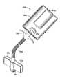
本発明の別の態様の硬化光アセンブリーは、広く数値40で指定され、そして図5 および7 〜11に示されている。図5 に示すように、この態様におけるアセンブリー40は充電可能な電池のような形態の出力源を含むケース42を含む。ケース42は、長く延びたハウジング44に連結されている。
【0024】
ハウジング44は、好ましくは、その形状が整復可能であり、且つ、多くの異なる自立形状のいずれかに変えられることができるるように作られている。例えば、ハウジング44は、真っ直ぐな長手軸を有することができ、または、多くの異なる弧のうちのいずれかの湾曲した長手軸を有するように変えられることができる。ハウジング44はグースネックランプ等のために使用されるような相互に連結された一連の環状セクションを提供することにより作られることができる。
【0025】
ハウジング44は光源を含む外側末端部分46を有する。好ましくは、光源は、発光ダイオードの固体素子発光器48( 図5 のみ) である。本明細書中で使用されるときに、用語「固体素子発光器」とは、正孔と電子の再結合により電気エネルギーを電磁線に変換するあらゆる装置を意味する。固体素子発光器の例は、半導体発光ダイオオード、半導体レーザーダイオード、ポリマー発光ダイオードおよびエレクトロルミネッセンス装置( 即ち、変化している電場を受けている固体の燐光物質により電気エネルギーを光エネルギーに変換する装置) を含む。
【0026】
必要に応じて、外側末端部分46は発光器48のための焦点レンズ、例えば、一般的に入手可能な発光ダイオードをカバーするドーム型レンズを含むことができる。レンズは、好ましくは、発光器から放出された光の大半をハウジング44の長手軸とほぼ平行である前方方向に向けるような形状になっている。
【0027】
発光器48は、ハウジング44内に延びているワイヤー対( 示していない) によりケース42内の電池出力源に接続されている。バネ押し指スイッチ50はケース42に移動可能に接続されており、そして発光器48と出力源との間に延びているワイヤーのいずれかにより電気接続されている。
【0028】
外側末端部分46は通路36の境界内に入るように十分小さいサイズである。例えば、もし、通路36が0.04インチ(1mm) の直径を有し、そして外側末端部分46は半球形状を有するならば、半球の直径は0.03インチ(0.75mm)である。半球は、好ましくは通路36の直径よりほんの少し小さい直径を有する。
【0029】
必要に応じて、外側末端部分46は、それが接触する歯科矯正用接着剤から容易に剥離する手段を具備している。このような手段は、例えば、シリコーンポリマーのような剥離コーティングまたは眼鏡のレンズをコーティングするために使用されるコーティングに似た硬質コーティングを含むことができる。
【0030】
硬化光アセンブリーは、ハウジング44に連結された少なくともタブ52をも含む。示した態様において、1 対のタブ52が提供されており、互いに反対方向に外側に広がっており、そしてハウジング44から外側に広がっている。タブ52は外側末端部分46に直ぐ隣に隣接した中央の円筒部材に連結されている。ハウジング44は円筒部材の中央を通過する孔を通して延びている。
【0031】
タブ52はアーチワイヤースロット34の断面形状に相補的な横断断面形状を有する。より詳細には、タブ52はアーチワイヤースロット34の噛み合わせ- 歯肉幅よりほんの少し小さい幅を有する。一般に、歯科矯正ブラケットは0.018 インチ(0.46mm)および0.022 インチ(0.56mm)の公称の噛み合わせ- 歯肉の寸法を有する長方形のアーチワイヤースロットを有して提供される。適合するアーチワイヤーの噛み合わせ- 歯肉の寸法と同様のタブ52の幅は、このような対応するアーチワイヤースロットの寸法よりほんの少し小さく、このことにより、タブは過度の遊び、即ち、「緩み」がなく、容易にアーチワイヤーに挿入されまたは取り外されることができる。
【0032】
好ましくは、タブ52の外側末端間の距離は最も広いであろうブラケットのアーチワイヤースロットの近心- 遠心末端の距離と同一であるかまたは若干大きく、それにより、所望のときに、ブラケットの動きを良好に制御できる。
【0033】
必要に応じて、中央の円筒部材を含むタブ52はハウジング44に取り外し可能に付けられることができ、そして、摩擦またはラッチのような他の構造により固定される。結果として、タブ52は所望の時にハウジング44から取り外されることができ、そして、他のブラケットに適合するための異なる噛み合わせ- 歯肉寸法を有するタブのような他のタブと取り替えられることができる。好ましくは、タブ52をハウジング44に連結する構造はハウジング44の長手軸の回りの弧においてタブ52の相対的な回転を防ぎ、それにより、ブラケット20の動きおよび最終の配置を制御するためにハウジング44を回転することができる。タブ52を取り外すために、ハウジング44はケース42に取り外し可能に連結され、または、外側末端部分46はハウジング44の残りの部分に取り外し可能に連結されることができる。
【0034】
必要に応じて、タブ52は、タブ52の視覚的な観測を容易にするように、ブラケット20の材料と対照的な色を有する。例えば、タブ52は、タブ52とブラケット20の金属色とのコントラストを高めるために、黒色を有するか、または黒色コーティングを有することができる。このような色のコントラストは、歯科矯正医がタブ52を容易に位置合わせすることを可能にし、そしてそれ故、患者の歯における最終的な意図した位置にブラケット20を移動するときに、患者の望ましい噛み合わせ平面にアーチワイヤースロット34を位置合わせすることを可能にする。
【0035】
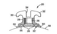
ブラケット20とともに硬化光アセンブリー40を使用する1 つの方法を図6 〜11に示す工程により示す。最初に、一定量の光硬化性結合接着剤56( 例えば、3M Unitek のTRANSBOND ブランドの接着剤) を開口部24の上のペグ26と接触したブラケット基底部22上に配置する。次に、ブラケット20を接着剤とともに患者の歯58の外側表面に配置する。
【0036】
好ましくは、基底部20上に配置される接着剤56の量は、歯56にブラケット20を最終的に結合するために必要な接着剤56の量よりも多量である。結果として、しっかりと固定するまで歯58にブラケット20を押しつけるときに、接着剤56の一部分60はブラケットの基底部22の4 つの面から押し出される。移動および接着剤56のはみ出しはブラケット基底部22と歯56の表面の間の領域での接着剤56のギャップまたは空隙が起こる可能性を下げる。
【0037】
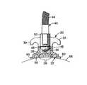
次に、図7 〜8 に示すように、硬化光アセンブリー40のハウジング44は、図7 において矢印で示した方向で、且つ、外側末端部分46を含むハウジング44の長手軸が通路36の中央の長手軸と同一直線上になるようにブラケット20に向かって移動される。更に、ハウジング44は、アーチワイヤースロット34とタブ52を位置合わせするために、ハウジング長手軸の周囲に必要なときに回転される。光硬化アセンブリー40は、図9 および10に示すように、外側末端部分46が通路36に入り、そしてタブ52がアーチワイヤースロット34に受け入れられるまでブラケット20に向かって移動しつづける。
【0038】
次に、歯科矯正医は歯58上の正確な望ましい位置にブラケット20を配置するために必要とされるときに、歯58に対してブラケット20を若干移動する。例えば、歯科矯正医は、アーチワイヤースロット34が患者の噛み合わせ平面に位置合わせされ、そしてタイウィング30、32の縁が歯58の長手軸と位置合わせされるまでブラケット20を移動することができる。タブ52および外側末端部分46はブラケット20の移動を制御するように機能するから、噛み合わせ- 歯肉方向、近心- 遠心方向または通路36の中央軸の周囲の回転移動における移動を含めたブラケット20の配置は、歯58に対してハウジング44を移動することにより行われる。
【0039】
ある場合には、ハウジング44の形状はあるブラケットの配置を容易にするために変えられることができる。例えば、臼歯または小臼歯にブラケットを結合するために硬化光アセンブリー40を使用するときには、歯科矯正医は、図5 に示すように、ハウジング44を湾曲した形状に曲げたいであろう。または、ブラケット20を患者の切歯または側切歯のような比較的に届きやすい歯に配置するときには、歯科矯正医はハウジング44の形状を直線形状に変えたいであろう。
【0040】
次に、図9 に示すように、固体素子発光器48は、スイッチ50を押すことにより活性化される。発光器48から放出される光は、ブラケットのボディー28の中央セクションと歯58との間にある接着剤の部分( 図11において62と指定している) に達する。接着剤部分62は曲がり、そしてブラケット20を歯58に一時的に固定する「粘着( タック) 」結合を提供する。
【0041】
次に、図11に示すように、外側末端部分46を通路36から取り除き、そしてタブ52をアーチワイヤースロット34から取り除くまで矢印の方向にハウジング44をブラケットボディー28から離れるように移動することにより硬化光アセンブリー40はブラケット20から取り除かれる。好ましくは、歯科矯正医は、その後、歯科用深診器または他の器具を使用して、ブラケット基底部22の4 つの周囲縁に隣接した歯58から、はみ出している接着剤部分60を除去する。もし、例えば、ブラケット20が洗浄の間に不慮にぶつかり、または妨害されても、通常に、ブラケット20を保持するために十分な結合力をもって、硬化した接着剤部分62はブラケット20を歯58に連結する。しかし、通路34における光の使用は、硬化した部分62以外の接着剤56を実質的に硬化せず、そしてこの為、はみ出された接着剤部分60は硬化せず、そして歯の表面から容易に除去されることができる。
【0042】
次に、ブラケット基底部22と歯58との間の接着剤56の残りの部分はブラケット基底部22の周囲縁に光を向けることにより硬化される。所望ならば、このような周囲硬化のためにブラケット20から取り外して硬化光アセンブリー40を使用するか、または、より強い光を放出することができる別の硬化光アセンブリーを使用することができる。好ましくは、光は基底部の4 つの周囲縁のうちの少なくとも2 つの縁、例えば、基底部22の近心側および遠心側の縁に光を向けることができる。
【0043】
別の手順として、ブラケット20の移動を制御することに加えて、歯にブラケット20をしっかりと押しつけるために硬化光アセンブリー40を使用することができる。所望ならば、ブラケット20は、ブラケット20を歯58の表面上に配置する前にブラケット20をタブ52に連結することができる。
【0044】
本発明の1 つの大きな利点は、歯科矯正医が直接的な結合のために従来から使用されている歯科矯正接着剤よりも低い粘性である接着剤を使用することが可能なことである。より低い粘性の接着剤は、より粘性の接着剤よりもブラケット基底部22の添窩および他の微細構造の周囲を流れ、その為、このようなより粘性の接着剤よりも高い結合強度を提供する。接着剤が硬化する前の歯58の上でのブラケット20の流れは、光硬化アセンブリー40が粘着結合するまでブラケット20の移動を抑制するから避けることができる。しかし、過去において、比較的に粘性の接着剤が一般に好まれていた。というのは、このような接着剤は、歯58に配置した後のブラケット20のずれを防ぐからである。
【0045】
好ましくは、固体素子発光器48は、実質的に約413 ナノメートル〜約535 ナノメートルの範囲の波長を有する光を放出し、そして好ましくは約450 ナノメートルの波長で最も高い強度の光を放出する青色発光ダイオードである。適切な青色光発光ダイオードはNichia Chemical Industries, Ltd.のNo.NLPB500を含む。他の波長も可能である。LED の外側半球レンズは好ましくは通路36内に適合し、そして通路36の長手軸に沿って殆どの光を指向するように研削されている。好ましくは、通路36内において発光器48により放出される光は約10秒以内に、そしてより好ましくは約4 秒以内に接着剤部分62を硬化するために十分な強度のものである。
【0046】
本発明の別の態様による硬化光アセンブリー40a の第二の態様を図12に示す。アセンブリー40a は、この場合に、バルブ43a のような光源を含むケース42a を含む。または、単一の固体素子発光器、または、一群の固体素子発光器( 例えば、上記の青色発光ダイオード) はバルブ43a の代わりに配置されてよい。
【0047】
ケース42a は、また、バルブ43a に電気接続されたバッテリー41a を含む出力源を含む。バネ押し指スイッチ50a はケース42a に移動可能に接続されている。スイッチ50a を押すと、バッテリー41a はバルブ43a に電力供給する。
【0048】
アセンブリー40a は、また、この場合には光学繊維束を含む長いハウジング44a を含む。光学繊維束は、幾分可撓性であるが、元に戻したときには所望の形状を保持するために十分に剛性である。この態様におけるハウジング44a は束の周囲に配置された繊維の外側クラッドが提供されている。または、光学繊維の束は、可撓性ハウジング( 例えば、上記のグースネック) の内側に入れられることができる。別の態様として、単一の光学繊維は使用されることができ、または、代わりに、このようなクラッドを周囲に有する、別個の可撓性チューブ状部材を含むことができる。
【0049】
ハウジング44a は、好ましくは上記のような剥離コーティングまたは他の剥離手段を具備した大きな外側末端部分46a を含む。更に、1 対のタブ52a は外側末端部分46a の直ぐ隣に隣接したハウジング44a に接続されている。タブ52a は上記のタブ52と同一である。
【0050】
本発明の別の態様による硬化光アセンブリー40b を図13に示す。アセンブリー40b は、この場合には、比較的に小さいケース42b を含み、そしてスケール通りに例示されていない。ケース42b は、その中に含まれる従来のAAA サイズの電池よりもほんの少しだけ大きい。好ましくは、ケース42b は掴みやすく、そして操作しやすいように鉛筆と同様の形状を有する。ケース42b は、外側末端部分46b を有する比較的に小さいハウジングに接続されており、そして所望により取り外し可能に接続されている。
【0051】
固体素子発光器( 例えば、上記の青色発光ダイオード) は外側末端部分46b 中に収納されている。更に、上記のタブ52と同様の1 対のタブ52b はハウジング44b に接続されている。押しボタン式スイッチ50b はケース42b の側に取り付けられており、所望の時に回路を閉じそして固体素子発光器に電力供給することができる。
【0052】
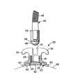
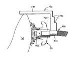
本発明の更に別の態様にる硬化光アセンブリー40c を図14に示す。アセンブリー40c は図5 および7 〜11に示した硬化光アセンブリー40と若干似ているが、アセンブリー40c はハウジング44c に固定されたブラケット高さゲージ70c を含む。所望により、ゲージ70c はハウジング44C 上にスライド可能に配置されそして摩擦により保持されたスリーブを含み、それにより、ゲージ70c は所望のときにハウジング44c から外せるようになっており、そして同様のまたは異なるゲージと取り替えられることができる。
【0053】
第一レッグおよび第一レッグに一体に連結された第二レッグ74c を有する、ほぼL 型形状を有する。第二レッグ74c の下側部分が歯58の噛み合わせ縁と接触しているときに、歯58の最外末端( 即ち、噛み合わせ縁または切歯縁) から噛み合わせ- 歯肉方向における特定の距離にブラケット20のアーチワイヤースロットがが配置されるように、第一レッグ72c の長さは選択される。ゲージ70c は、それ故、アセンブリー40c の外側末端部分46c から光が放出されて、その後、ブラケット20を定位置に保持する時間まで、歯58の上の所定の位置にブラケット20を固定する。
【0054】
好ましくは、第一レッグ72c は歯58の噛み合わせ縁からのブラケット20のアーチワイヤースロットの距離を決定するための更なる構造を提供するための一連の印を含む。示した態様において、印は一対の縁またはショルダー76c を含み、それは、第二レッグ74c が噛み合わせ縁と接触しているときに提供される高さ以外の歯58の高さにブラケット20を配置したい場合に、所望ならば、歯の噛み合わせ縁に目で見て位置合わせされることができる。他の印および調節可能な高さゲージも可能である。
【0055】
当業者は、上記で詳細に記載した態様の他の変更も可能であることを認識するであろう。例えば、上記の硬化光アセンブリーの態様において記載したバッテリーは、光源の光を輸送する、ベースユニットからハウジングに延びた1 対のワイヤーを具備した、ラインカレントに接続されたベースユニットで置き換えることが可能である。または、ラインカレントに接続されたベースユニット( 例えば、ORTHOLUX XT ブランドの硬化光ユニット、カタログ番号704-804;3M Unitek)は、ハウジングの外側末端部分へ、単一の光学繊維または光学繊維束により光学的に且つ取り外し可能に接続された光源を含むことができる。更に、指操作スイッチ50、50a または50b はフットペダルスイッチまたは感圧スイッチで置き換えられてよく、それは、硬化光アセンブリー40、40a 、40b 、40c によりブラケット20に十分な圧力が印加されたときに発光器を活性化するように操作可能である。
【0056】
更に、ブラケット20は、微細ワイヤーメッシュスクリーニングに似たメッシュパッドを有する基底部を有することができる。もしメッシュパッドがメッシュスクリーニングに結合された金属ホイルの層を含むならば、ホイルは基底部の開口部として機能する1 個以上の孔を有する。
【0057】
金属材料以外の材料から製造されたブラケットを使用することもできる。例えば、ブラケットは、透明な、半透明なまたは不透明なプラスティックまたはセラミック材料から作られていることができる。もしブラケットが光を透過する材料からできているならば、硬化光アセンブリーから放出される光の強度は、好ましいことに、比較的に弱い。このような弱い強度はブラケットのボディーの中央セクションの直下の接着剤を硬化するために十分であるが、はみ出した接着剤を歯の表面から容易に除去することができるように、ブラケットの基底部の周辺縁付近の接着剤を硬化するためには不十分である。
【0058】
アーチワイヤースロットライナーを有するブラケットも本発明で使用されてよい。ライナーを有するブラケットの適切な例は、例えば、米国特許第5,380,196 号および第5,366,372 号に記載されている。このような場合には、ライナーはブラケットボディーの一部として含まれており、そして、ブラケットの基底部の中央部分の直下の接着剤へ光が透過するように、ブラケット基底部における開口部と位置合わせされた通路を提供するための孔を含むであろう。
【0059】
本発明は、間接結合手順を使用することもできる。間接結合手順において、ブラケットのセットは患者の歯の模型に実験室内で一時的に粘着結合され、各ブラケットは互いの相対位置を維持し、そして患者の模型に対する相対位置を維持する。ブラケットのセットはその後、模型からユニットとして取り外され、そして相対位置を維持しながら患者の実際の歯に再結合される。
【0060】
多くの他の変更および追加も可能であり、そして本発明の範囲を逸脱することなく有利に使用されることができる。従って、本発明は、上記で詳細に記載された現在好ましい態様によって限定されると考えられるべきでなく、特許請求の範囲およびその等価物によってのみ限定されるべきである。
【図面の簡単な説明】
【図1】ブラケットの頬−唇側の面に対して見たときの、本発明の1態様により製造された歯科矯正ブラケットの正面図である。
【図2】ブラケットの歯に面する基底部に対して見たときの図1の背面図である。
【図3】図1および2に示した、図1の線3−3に沿って取った側断面図である。
【図4】図1〜3に示した、ブラケットの噛み合わせ面に対して見たときの側断面図である。
【図5】本発明の別の態様に係る硬化光アセンブリーの斜視図(スケール通りでない)であって、図1〜4の示したブラケットとともに使用されるように調整されたものである。
【図6】図3と幾分似通った図であるが、ブラケットは歯の上に配置され、そして一定量の結合接着剤と接触して示されている、側断面図である。
【図7】図6と幾分似通った図であるが、ブラケットの通路に向かって移動している硬化光アセンブリーを更に示した図である。
【図8】図7に示したブラケットおよび硬化光アセンブリーの斜視図である。
【図9】図7と幾分似通った図であるが、硬化光アセンブリーがブラケットの通路内に完全に受け入れられており、それにより、歯科矯正医が最初に歯にブラケットを正確に配置することができ、そして、ここで、光は、次に、通路の直下の接着剤部分を硬化するように活性化されることを示すものである。
【図10】図9に示したブラケットおよび硬化光アセンブリーの斜視図である。
【図11】図9と幾分似通った図であるが、通路の直下の接着剤は硬化されており、そして、硬化光アセンブリーは通路から取り外されている図である。
【図12】本発明の別の態様に係る硬化光アセンブリーの斜視図(スケール通りでない)である。
【図13】本発明の更なる態様に係る硬化光アセンブリーの部分斜視図(スケール通りでない)である。
【図14】歯の上に配置されたブラケットおよび接着剤とともに、本発明の別の態様に係る硬化光アセンブリーの部分断面図を示す。
【符号の説明】
20…ブラケット
22…基底部
24…開口部
26…直立ペグ
28…ボディー
30…タイウィング
32…タイウィング
34…アーチワイヤースロット
36…通過路
40…硬化光アセンブリー
42…ケース
44…ハウジング
46…外側末端部分
50…スイッチ
52…タブまたはカップラー
58…歯[0001]
The present invention relates to an improved orthodontic bracket and light curing assembly, which together increase the bond strength between the bracket and the tooth, particularly just below the central portion of the bracket base.
[0002]
Orthodontic treatment involves the movement of teeth to the desired location for proper biting. During the procedure, a small slotted orthodontic appliance called a bracket is connected to the teeth and an archwire is placed in the slot of each bracket. The archwire forms a track to guide the teeth to move to the correct orthodontic position.
[0003]
Many commercially available orthodontic brackets are adapted to be bonded directly to the surface of a patient's teeth by means of an orthodontic bonding adhesive. Certain types of adhesives, such as CONCISE brand adhesives (3M Unitek), are initially supplied as two separate components and become self-curing when they are mixed. Such two-component adhesives, however, have a limited “pot life” during which only the orthodontist applies the adhesive to the base of the bracket, attaches the bracket onto the tooth, and adheres The bracket can be moved to some desired position before the agent begins to cure. Other adhesives, such as TRANSBOND brand adhesives (also 3M Unitek) are light curable and begin to cure when the light source is directed at the adhesive. Photo-curing adhesives are preferred by many orthodontists because the “pot life” length can be selected as needed. In use, the bracket can be carefully placed on the patient's teeth and moved as desired until the orthodontist is satisfied with the position of the bracket. Advantageously, the adhesive does not cure until the light source is directed at the adhesive.
[0004]
Many attempts have been made over the years to increase the strength between the bracket and the teeth. Some brackets, for example, have a rough, knurled, or indented outer base surface, and other brackets include at least one layer of irregularly shaped fragments or spherical particles. Includes the basal surface. Such a base surface provides a high surface area that can be used for contact with the adhesive, thereby increasing the bond strength between the bracket and the tooth.
[0005]
Some brackets have a base that provides undercut regions. A groin in the base allows the adhesive to form a mechanical interlock with the bracket when cured. For example, the irregularly shaped fragments or spherical particles described above may provide an axillary region. As another example, the base of some brackets have a fine mesh metal “screen” or pad that provides a mechanical interlock when embedded in a cured adhesive. Other brackets, such as those described in US Design Patent No. 290,040, have a series of gutter grooves that provide a mechanical interlock with the cured adhesive. U.S. Pat.Nos. 4,094,068 and 5,435,720 describe a bracket having a base with a perforated hole or notch that causes the adhesive to flow in and create a large head that serves to improve the retention of the bracket against the teeth. .
[0006]
However, there is a continuing need in the art to improve the strength of the bond between a particular type of bracket and the patient's teeth to avoid spontaneous unintentional shedding of the bracket during the procedure. In some cases, when the patient is subjected to a relatively large force, such as biting a relatively hard food, the bond does not have sufficient strength to hold the bracket on the tooth. In other cases, the bracket can be decoupled from the force applied by an archwire, an orthodontic aid or a fitting connected to the bracket. Early debonding of orthodontic brackets is troublesome for both orthodontists and patients and is best avoided. This is because the patient usually has to return to the orthodontist to reattach the dropped bracket or replace it with a new bracket to resume treatment.
[0007]
Furthermore, recent efforts have been directed to increasing bond strength when photocurable bond adhesives are used with metal brackets. When a light curable adhesive is used with a bracket made from translucent or transparent plastic, ceramic or other material, light from the curing device usually passes through the bracket, and with the bracket base Most if not all of the adhesive between the teeth is cured. However, the metal bracket substantially blocks the passage of light to the central portion of the bracket base, so that the adhesive in the vicinity of the central portion remains uncured. Often the curing light is directed to the adhesive along two or more edges of the base of the metal bracket, but even if this is done, the bracket's intent Insufficient amount of adhesive to cure to prevent debonding.
[0008]
Another difficulty sometimes encountered in orthodontic bracket bonding procedures relates to the removal of excess adhesive after the bracket is installed and before the adhesive is cured. In many joining procedures, the bracket is carefully placed in place and then pressure is applied to secure the bracket to the adhesive. Often, orthodontists have an excessive amount of air before installation so that the entire surface of the bracket base is in contact with the adhesive and there are no air bubbles or gaps between the bracket and the tooth in the absence of adhesive. You will choose to apply an adhesive. During installation, excess adhesive is pushed out from just below the bracket base to the area of the patient's teeth adjacent to the periphery of the bracket base. Thereafter, the dental extruding instrument or other instrument is used to remove and remove the extruded adhesive from the tooth surface.
[0009]
However, during the removal of excess adhesive, the deep diagnostic instrument may collide with the bracket and move slightly from its intended position. In such cases, it is often not recommended to simply return the bracket to its original position. This is because insufficient adhesive remains under the bracket for a satisfactory bond and voids can occur. Instead, usually remove the bracket and adhesive from the tooth, add additional adhesive to the bracket base, reposition the bracket on the tooth, install and remove the newly extruded adhesive It is recommended that the procedure eventually takes some time.
[0010]
The present invention overcomes the above-mentioned problems associated with conventional brackets, light curable units and procedures, and is an improvement for joining the adhesive portion directly between the central portion of the bracket and the patient's teeth. By providing an improved method and apparatus. If desired, the method and apparatus described herein temporarily secures the bracket to the tooth without hardening of the adhesive extruded from the peripheral edge of the bracket base during bracket installation. Can be used advantageously. Once in this way, once the bracket is temporarily secured to the teeth, excess extruded adhesive is easily removed by dental or other instruments, but the instrument is unintentionally Even when bumped, the hardened part of the adhesive will prevent the bracket from moving. Following removal of the extruded adhesive, the portion of the adhesive between the peripheral edge of the bracket base and the teeth is cured to increase the bond strength of the adhesive to a value useful for orthodontic treatment. A curing unit can be used for this purpose.
[0011]
More particularly, the present invention in one aspect relates to a combination of an orthodontic bracket and a curing light assembly. The combination includes an orthodontic bracket having a base with an outer surface for direct connection to a tooth, wherein the base includes a central portion having at least one opening. The bracket also includes a body that extends from the base in a direction away from the outer surface. The bracket also includes at least one tiewing extending outwardly from the body and includes a slot adjacent the tiewing for receiving the archwire. The body includes a central section having a passage aligned with the base opening. The combination also includes a curing light assembly having a housing with an outer end portion that is large enough to be received in the passage of the bracket body. The curing light assembly includes a light source coupled to the housing that emits light from the outer end portion to cure the bonding adhesive in contact with the central portion of the bracket when the outer end portion of the housing receives light in the passage. Including.
[0012]
Another aspect of the invention relates to an orthodontic bracket that includes a base having an outer surface for direct bonding to a tooth, wherein the base includes a central portion having at least one opening. The bracket also includes a body that extends from the base in a direction away from the outer surface. The body includes a central portion having a passage. At least one tie wing extends outwardly from the body and the slot is adjacent to the tie wing for receiving the archwire. The body includes a passage, which is aligned with a base opening for receiving a light source for curing the photocurable bonding adhesive in contact with the central portion of the base.
[0013]
The present invention also relates to an orthodontic curing light assembly that includes a light source coupled to an outer end portion and a housing. The light source is operable to emit light in a direction away from the outer end portion. The assembly also includes a coupler for removably connecting the outer end portion to the orthodontic bracket.
[0014]
The present invention is particularly advantageous when used with brackets made from opaque materials such as stainless steel or other materials. This is because the path of the bracket could allow light to reach the adhesive under the central portion of the bracket base, otherwise it would not have substantially hardened. The resulting bond strength between the bracket and the tooth is high, and significantly reduces the possibility of unintentional, spontaneous bracket debonding during treatment.
[0015]
Further details of the invention are defined in the features of the claims.
[0016]
An orthodontic bracket made in accordance with the principles of the present invention is broadly designated by the
[0017]
The
[0018]
The
[0019]
The
[0020]
The
[0021]
The
[0022]
Preferably, the
[0023]
Another embodiment of the curing light assembly of the present invention is broadly designated by the numeral 40 and is shown in FIGS. 5 and 7-11. As shown in FIG. 5, the
[0024]
The
[0025]
The
[0026]
If desired, the
[0027]
The
[0028]
The
[0029]
Optionally, the
[0030]
The curing light assembly also includes at least a
[0031]
[0032]
Preferably, the distance between the outer ends of the
[0033]
If desired, the
[0034]
Optionally, the
[0035]
One method of using the curing
[0036]
Preferably, the amount of adhesive 56 disposed on the
[0037]
Next, as shown in FIGS. 7-8, the
[0038]
The orthodontist then moves the
[0039]
In some cases, the shape of the
[0040]
Next, as shown in FIG. 9, the solid
[0041]
Next, as shown in FIG. 11, the
[0042]
Next, the remaining portion of the adhesive 56 between the
[0043]
As an alternative procedure, in addition to controlling the movement of the
[0044]
One major advantage of the present invention is that it is possible for orthodontists to use adhesives that have a lower viscosity than orthodontic adhesives conventionally used for direct bonding. Lower viscosity adhesives flow around the
[0045]
Preferably, the solid
[0046]
A second embodiment of a curing
[0047]
[0048]
The
[0049]
The
[0050]
A curing
[0051]
A solid state light emitter (eg, the blue light emitting diode described above) is housed in the
[0052]
A curing
[0053]
It has a generally L-shaped configuration with a first leg and a
[0054]
Preferably, the
[0055]
Those skilled in the art will recognize that other variations of the embodiments detailed above are possible. For example, the battery described in the curing light assembly embodiment above can be replaced with a base unit connected to a line current with a pair of wires extending from the base unit to the housing that carries the light of the light source. It is. Alternatively, a base unit connected to the line current (e.g. ORTHOLUX XT brand curing light unit, catalog number 704-804; 3M Unitek) can be optically connected to the outer end of the housing by a single fiber or fiber bundle And a light source connected removably. In addition, the finger operated
[0056]
In addition, the
[0057]
Brackets made from materials other than metal materials can also be used. For example, the bracket can be made from a transparent, translucent or opaque plastic or ceramic material. If the bracket is made of a light transmissive material, the intensity of light emitted from the curing light assembly is preferably relatively weak. Such weak strength is sufficient to cure the adhesive directly under the central section of the bracket body, but the base of the bracket so that the protruding adhesive can be easily removed from the tooth surface. Insufficient to cure the adhesive near the peripheral edge of.
[0058]
A bracket having an archwire slot liner may also be used in the present invention. Suitable examples of brackets having a liner are described, for example, in US Pat. Nos. 5,380,196 and 5,366,372. In such a case, the liner is included as part of the bracket body, and the opening and position in the bracket base is such that light is transmitted to the adhesive directly below the central portion of the bracket base. It will include a hole to provide a combined passage.
[0059]
The present invention can also use an indirect binding procedure. In the indirect bonding procedure, the set of brackets is temporarily adhesively bonded to the patient's dental model in the laboratory, with each bracket maintaining a relative position to each other and maintaining a relative position to the patient model. The set of brackets is then removed as a unit from the model and reconnected to the patient's actual teeth while maintaining the relative position.
[0060]
Many other modifications and additions are possible and can be used advantageously without departing from the scope of the present invention. Therefore, the present invention should not be considered limited by the presently preferred embodiments described in detail above, but only by the claims and their equivalents.
[Brief description of the drawings]
FIG. 1 is a front view of an orthodontic bracket made in accordance with an aspect of the present invention when viewed against the cheek-lip side surface of the bracket.
FIG. 2 is a rear view of FIG. 1 when viewed from the base facing the teeth of the bracket.
3 is a cross-sectional side view taken along line 3-3 of FIG. 1 shown in FIGS. 1 and 2. FIG.
FIG. 4 is a side cross-sectional view of the bracket shown in FIGS.
FIG. 5 is a perspective view (not to scale) of a curing light assembly according to another aspect of the present invention, adjusted to be used with the bracket shown in FIGS.
FIG. 6 is a side cross-sectional view somewhat similar to FIG. 3, but with the bracket placed over the teeth and shown in contact with a quantity of bonding adhesive.
FIG. 7 is a view somewhat similar to FIG. 6, but further illustrating the curing light assembly moving toward the path of the bracket.
8 is a perspective view of the bracket and curing light assembly shown in FIG. 7. FIG.
FIG. 9 is a view somewhat similar to FIG. 7, but with the curing light assembly fully received within the path of the bracket, so that the orthodontist first accurately places the bracket on the tooth. And where the light is then shown to be activated to cure the adhesive portion directly under the passage.
10 is a perspective view of the bracket and curing light assembly shown in FIG. 9. FIG.
FIG. 11 is a view somewhat similar to FIG. 9, except that the adhesive directly under the passage has been cured and the curing light assembly has been removed from the passage.
FIG. 12 is a perspective view (not to scale) of a curing light assembly according to another embodiment of the present invention.
FIG. 13 is a partial perspective view (not to scale) of a curing light assembly according to a further aspect of the present invention.
FIG. 14 illustrates a partial cross-sectional view of a curing light assembly according to another aspect of the present invention, with brackets and adhesive disposed on the teeth.
[Explanation of symbols]
20 ... Bracket
22… Base
24… Opening
26 ... upright peg
28 ... Body
30 ... Tie Wing
32 ... Tie Wing
34 ... Archwire slot
36 ... Passage
40 ... Curing light assembly
42 ... Case
44… Housing
46… Outer end part
50 ... Switch
52… Tab or coupler
58 ... Teeth
Claims (2)
Translated fromJapanese歯科矯正ブラケット(20)は歯(58)に直接結合するための外側表面を有する基底部(22)を有し、前記基底部(22)は少なくとも1 個の開口部(24)を有する中央部分を含み、前記ブラケット(20)は前記外側表面から離れる方向に向かって基底部(22)から延びているボディー(28)を有し、前記ブラケット(20)は、更に、ボディー(28)から外側に向かって延びている少なくとも1 個のタイウィング(30 、32) 、および、アーチワイヤーを受け入れるための前記少なくとも1 個のタイウィング(30 、32) に隣接したスロット(34)をも含み、前記ボディー(28)は前記少なくとも1 個の開口部(24)と位置合わせされた通路(36)を有する中央セクションを有し、そして、
硬化光アセンブリー(40 、40a 、40b 、40c)は、前記通路(36)内に受け入れるために十分なサイズの外側末端部分(46 、46a 、46b 、46c)を有するハウジング(44 、44a 、44b 、44c)を有し、前記硬化光アセンブリー(40 、40a 、40b 、40c)は前記外側末端部分(46 、46a 、46b 、46c)が前記通路(36)に挿入されたときに、前記基底部(22)の前記中央部分と接触している結合接着剤を硬化するために、前記外側末端部分(46 、46a 、46b 、46c)から光を放出するための前記ハウジング(44 、44a 、44b 、44c)に接続されている光源(48 、43a)を含む、組み合わせ物。A combination comprising an orthodontic bracket and a curing light assembly,
The orthodontic bracket (20) has a base (22) having an outer surface for direct coupling to the teeth (58), the base (22) having a central portion having at least one opening (24). The bracket (20) has a body (28) extending from the base (22) in a direction away from the outer surface, and the bracket (20) is further outward from the body (28). And at least one tie wing (30, 32) extending toward the slot and a slot (34) adjacent to the at least one tie wing (30, 32) for receiving an archwire, The body (28) has a central section with a passage (36) aligned with the at least one opening (24), and
The curing light assembly (40, 40a, 40b, 40c) has a housing (44, 44a, 44b, 46c) having an outer end portion (46, 46a, 46b, 46c) of sufficient size to be received in the passage (36). 44c), and the curing light assembly (40, 40a, 40b, 40c) has the base portion (46, 46a, 46b, 46c) when the outer end portion (46, 46a, 46b, 46c) is inserted into the passage (36). 22) the housing (44, 44a, 44b, 44c) for emitting light from the outer end part (46, 46a, 46b, 46c) to cure the bonding adhesive in contact with the central part of ) Including a light source (48, 43a) connected to.
前記基底部(22)が少なくとも1 個の開口部(24)を有する中央部分を含み、且つ、前記ボディー(28)が前記基底部(22)の中央部分に接触している光硬化性結合接着剤を硬化するための光源(48 、43a)を受け入れるための前記少なくとも1 個の開口部(24)と位置合わせされた通路(36)を含むことを特徴とする、歯科矯正ブラケット。A base (22) having an outer surface for direct coupling to a tooth (58), wherein the base (22) includes a central portion having at least one opening (24) from the outer surface; A body (28) extending away from the base (22) in a remote direction, at least one tie wing (30, 32) extending outward from the body, and at least one for receiving an archwire An orthodontic bracket (20) comprising a slot (34) adjacent to a tie wing (30, 32),
A photocurable bond bond wherein the base (22) includes a central portion having at least one opening (24) and the body (28) is in contact with the central portion of the base (22) An orthodontic bracket comprising a passage (36) aligned with the at least one opening (24) for receiving a light source (48, 43a) for curing the agent.
Applications Claiming Priority (2)
| Application Number | Priority Date | Filing Date | Title |
|---|---|---|---|
| US08/575095 | 1995-12-19 | ||
| US08/575,095US5711665A (en) | 1995-12-19 | 1995-12-19 | Method and apparatus for bonding orthodontic brackets to teeth |
Publications (2)
| Publication Number | Publication Date |
|---|---|
| JPH09173356A JPH09173356A (en) | 1997-07-08 |
| JP3805846B2true JP3805846B2 (en) | 2006-08-09 |
Family
ID=24298920
Family Applications (1)
| Application Number | Title | Priority Date | Filing Date |
|---|---|---|---|
| JP33422696AExpired - Fee RelatedJP3805846B2 (en) | 1995-12-19 | 1996-12-13 | Orthodontic bracket and curing light assembly |
Country Status (4)
| Country | Link |
|---|---|
| US (1) | US5711665A (en) |
| EP (2) | EP1484029A3 (en) |
| JP (1) | JP3805846B2 (en) |
| DE (3) | DE29624613U1 (en) |
Families Citing this family (178)
| Publication number | Priority date | Publication date | Assignee | Title |
|---|---|---|---|---|
| DE29709228U1 (en)* | 1997-05-26 | 1998-09-24 | THERA Patent GmbH & Co. KG Gesellschaft für industrielle Schutzrechte, 82229 Seefeld | Light curing unit |
| GB2329756A (en)* | 1997-09-25 | 1999-03-31 | Univ Bristol | Assemblies of light emitting diodes |
| US6200134B1 (en) | 1998-01-20 | 2001-03-13 | Kerr Corporation | Apparatus and method for curing materials with radiation |
| EP0950383A3 (en)* | 1998-04-14 | 2002-06-19 | DENTSPLY DETREY GmbH | Portable photocuring device |
| SE513533C2 (en)* | 1998-07-01 | 2000-09-25 | Kent Saefstroem | tooth Jewelery |
| US6077073A (en)* | 1998-09-15 | 2000-06-20 | Jacob; Gregory S. | Light emitting diode-array light apparatus |
| US6514075B1 (en) | 1998-09-15 | 2003-02-04 | Gregory S. Jacob | Dental curing apparatus for light-sensitive materials |
| US11026768B2 (en) | 1998-10-08 | 2021-06-08 | Align Technology, Inc. | Dental appliance reinforcement |
| US6824294B2 (en)* | 1999-09-24 | 2004-11-30 | Cao Group, Inc. | Light for use in activating light-activated materials, the light having a plurality of chips mounted in a gross well of a heat sink, and a dome covering the chips |
| US6926524B2 (en)* | 1999-09-24 | 2005-08-09 | Cao Group, Inc. | Curing light |
| US7066732B2 (en)* | 1999-09-24 | 2006-06-27 | Cao Group, Inc. | Method for curing light-curable materials |
| US7294364B2 (en)* | 1999-09-24 | 2007-11-13 | Cao Group, Inc. | Method for curing composite materials |
| US6955537B2 (en)* | 1999-09-24 | 2005-10-18 | Cao Group, Inc. | Light for use in activating light-activated materials, the light having a plurality of light emitting semiconductor chips emitting light of differing peak wavelengths to provide a wide light spectrum profile |
| US6929472B2 (en) | 1999-09-24 | 2005-08-16 | Cao Group, Inc. | Curing light |
| US6719559B2 (en) | 1999-09-24 | 2004-04-13 | Densen Cao | Curing light |
| US6910886B2 (en) | 1999-09-24 | 2005-06-28 | Cao Group, Inc. | Curing light |
| US6719558B2 (en) | 1999-09-24 | 2004-04-13 | Densen Cao | Curing light |
| US6988890B2 (en) | 1999-09-24 | 2006-01-24 | Cao Group, Inc. | Curing light |
| US6988891B2 (en)* | 1999-09-24 | 2006-01-24 | Cao Group, Inc. | Curing light |
| US7077648B2 (en)* | 1999-09-24 | 2006-07-18 | Cao Group, Inc. | Curing light |
| US6974319B2 (en)* | 1999-09-24 | 2005-12-13 | Cao Group, Inc. | Curing light |
| US6971876B2 (en) | 1999-09-24 | 2005-12-06 | Cao Group, Inc. | Curing light |
| US6981867B2 (en) | 1999-09-24 | 2006-01-03 | Cao Group, Inc. | Curing light |
| US6971875B2 (en) | 1999-09-24 | 2005-12-06 | Cao Group, Inc. | Dental curing light |
| US6755648B2 (en) | 1999-09-24 | 2004-06-29 | Cao Group, Inc. | Curing light |
| US6780010B2 (en) | 1999-09-24 | 2004-08-24 | Cao Group, Inc. | Curing light |
| US6755649B2 (en) | 1999-09-24 | 2004-06-29 | Cao Group, Inc. | Curing light |
| US6932600B2 (en)* | 1999-09-24 | 2005-08-23 | Cao Group, Inc. | Curing light |
| US6979193B2 (en) | 1999-09-24 | 2005-12-27 | Cao Group, Inc. | Curing light |
| US6318996B1 (en)* | 1999-10-05 | 2001-11-20 | Noureddine Melikechi | Method for curing a dental composition using a light emitting diode |
| US6342204B1 (en) | 1999-10-27 | 2002-01-29 | Dakota Dental Development, Inc | Flavored tooth conditioning compositions and methods for using the compositions to condition a tooth surface |
| US6342203B2 (en) | 1999-10-27 | 2002-01-29 | Dakota Dental Development, Inc. | Compositions for dentistry comprising an oil, to repair, restore, adhere to, or protect the surface of a tooth |
| US6371760B1 (en) | 1999-12-22 | 2002-04-16 | Tony Zavilenski | Method and apparatus for welding orthodontic article and an orthodontic article |
| US20040229186A1 (en)* | 2000-02-11 | 2004-11-18 | Slone Charles E. | Dental hand tool for interproximal dental restorations |
| US6419483B1 (en) | 2000-03-01 | 2002-07-16 | 3M Innovative Properties Company | Method and apparatus for curling light-curable dental materials |
| US7320593B2 (en) | 2000-03-08 | 2008-01-22 | Tir Systems Ltd. | Light emitting diode light source for curing dental composites |
| KR100379987B1 (en) | 2000-08-25 | 2003-04-16 | 조재형 | Convertable resin core system for positioning a bracket at a predetermined point of tooth surface |
| US6528555B1 (en)* | 2000-10-12 | 2003-03-04 | 3M Innovative Properties Company | Adhesive for use in the oral environment having color-changing capabilities |
| WO2002033312A2 (en)* | 2000-10-19 | 2002-04-25 | Reipur Technology A/S | A light-emitting assembly |
| US6620859B2 (en) | 2000-12-15 | 2003-09-16 | Dakota Dental Development, Inc. | Methods of preparing polymerizable dental compositions with improved taste or aroma, and that prevent oxygen-inhibited layer |
| US6482002B2 (en) | 2001-03-05 | 2002-11-19 | 3M Innovative Properties Company | Orthodontic appliance providing enhanced adhesive cure |
| US6468077B1 (en) | 2001-04-26 | 2002-10-22 | New Photonics, Llc | Compact device for curing dental compositions and method of curing |
| US6755647B2 (en) | 2001-04-26 | 2004-06-29 | New Photonics, Llc | Photocuring device with axial array of light emitting diodes and method of curing |
| US6511317B2 (en) | 2001-04-26 | 2003-01-28 | New Photonic, Llc | Device for curing photosensitive dental compositions with off-axis lens and method of curing |
| US6843370B2 (en)* | 2001-06-20 | 2005-01-18 | American Orthodontics | Package for prepasted orthodontic bracket |
| US6491408B1 (en)* | 2001-07-05 | 2002-12-10 | Spectronics Corporation | Pen-size LED inspection lamp for detection of fluorescent material |
| US7108504B2 (en) | 2001-07-10 | 2006-09-19 | Cao Group, Inc. | Light for use in activating light-activated materials, the light having insulators and an air jacket |
| US6799967B2 (en) | 2001-07-10 | 2004-10-05 | Cao Group, Inc. | Light for use in activating light-activated materials, the light having a plurality of light emitting single chip arrays |
| US6647761B2 (en)* | 2001-07-12 | 2003-11-18 | Mastercool, Inc. | Hand held flexible mount leak detector |
| US6749426B2 (en)* | 2001-10-02 | 2004-06-15 | Tp Orthodontics, Inc. | Bondable orthodontic appliance |
| US7106523B2 (en) | 2002-01-11 | 2006-09-12 | Ultradent Products, Inc. | Optical lens used to focus led light |
| US20030215766A1 (en)* | 2002-01-11 | 2003-11-20 | Ultradent Products, Inc. | Light emitting systems and kits that include a light emitting device and one or more removable lenses |
| US6940659B2 (en)* | 2002-01-11 | 2005-09-06 | Ultradent Products, Inc. | Cone-shaped lens having increased forward light intensity and kits incorporating such lenses |
| US20030148242A1 (en)* | 2002-02-05 | 2003-08-07 | Fischer Dan E. | Lightweight hand held dental curing device |
| EP1482857B1 (en)* | 2002-03-13 | 2013-01-16 | Christoph Von Mandach | Orthodontic set |
| US20030186195A1 (en)* | 2002-04-02 | 2003-10-02 | Comfort Biomedical, Inc. | Hand-held medical/dental tool |
| US20030186193A1 (en)* | 2002-04-02 | 2003-10-02 | Comfort Biomedical, Inc. | Hand-held medical/dental tool |
| AU2003222430A1 (en)* | 2002-05-02 | 2003-11-17 | Cadent Ltd. | Appliance for positioning orthodontic components |
| US20030230377A1 (en)* | 2002-06-14 | 2003-12-18 | Turvey Robert R. | Apparatus and method for automated splicing of closer tape |
| CA2493130A1 (en) | 2002-07-25 | 2004-02-05 | Jonathan S. Dahm | Method and apparatus for using light emitting diodes for curing |
| US7182597B2 (en)* | 2002-08-08 | 2007-02-27 | Kerr Corporation | Curing light instrument |
| AU2003298561A1 (en)* | 2002-08-23 | 2004-05-13 | Jonathan S. Dahm | Method and apparatus for using light emitting diodes |
| DE10250006A1 (en)* | 2002-10-25 | 2004-05-19 | Sirona Dental Systems Gmbh | Process for the correct production of a cavity, in particular a bone cavity, and instrument therefor |
| US20040101802A1 (en)* | 2002-11-21 | 2004-05-27 | Scott Robert R. | Wide bandwidth led curing light |
| US6890175B2 (en)* | 2002-12-18 | 2005-05-10 | Ultradent Products, Inc. | Cooling system for hand-held curing light |
| US6994546B2 (en)* | 2002-12-18 | 2006-02-07 | Ultradent Products, Inc. | Light curing device with detachable power supply |
| US7125249B1 (en)* | 2003-01-22 | 2006-10-24 | Great Lakes Orthodontics, Ltd. | Electrically powered orthodontic bracket and bonding method |
| USD530013S1 (en) | 2003-02-18 | 2006-10-10 | Ultradent Products, Inc. | Dental illumination device |
| US20040214131A1 (en)* | 2003-04-25 | 2004-10-28 | Ultradent Products, Inc., | Spot curing lens used to spot cure a dental appliance adhesive and systems and methods employing such lenses |
| US7192276B2 (en)* | 2003-08-20 | 2007-03-20 | Ultradent Products, Inc. | Dental curing light adapted to emit light at a desired angle |
| US20050074717A1 (en)* | 2003-10-03 | 2005-04-07 | 3M Innovative Properties Company | Method and apparatus for bonding orthodontic appliances to teeth |
| US7137812B2 (en) | 2003-10-03 | 2006-11-21 | 3M Innovative Properties Company | Apparatus for indirect bonding of orthodontic appliances and method of making the same |
| JP4051048B2 (en)* | 2003-12-05 | 2008-02-20 | 有限会社デント商事 | Orthodontic bracket |
| US7144250B2 (en) | 2003-12-17 | 2006-12-05 | Ultradent Products, Inc. | Rechargeable dental curing light |
| US7195482B2 (en)* | 2003-12-30 | 2007-03-27 | Ultradent Products, Inc. | Dental curing device having a heat sink for dissipating heat |
| US9492245B2 (en) | 2004-02-27 | 2016-11-15 | Align Technology, Inc. | Method and system for providing dynamic orthodontic assessment and treatment profiles |
| US7074040B2 (en)* | 2004-03-30 | 2006-07-11 | Ultradent Products, Inc. | Ball lens for use with a dental curing light |
| US7094052B2 (en)* | 2004-04-30 | 2006-08-22 | Norbert Abels | Orthodontic brackets with temporarily visible marking features |
| US7153130B2 (en)* | 2004-06-10 | 2006-12-26 | 3M Innovative Properties Company | Orthodontic appliance with removable insert |
| CN100594327C (en)* | 2004-06-15 | 2010-03-17 | 汉高公司 | High power LED electro-optic assembly |
| US7913002B2 (en)* | 2004-08-20 | 2011-03-22 | Advantest Corporation | Test apparatus, configuration method, and device interface |
| US7134872B2 (en)* | 2004-09-02 | 2006-11-14 | Norbert Abels | Colored orthodontic brackets |
| US7056116B2 (en)* | 2004-10-26 | 2006-06-06 | Ultradent Products, Inc. | Heat sink for dental curing light comprising a plurality of different materials |
| WO2006049703A1 (en)* | 2004-10-28 | 2006-05-11 | Henkel Corporation | Led assembly with led-reflector interconnect |
| JP2006167212A (en)* | 2004-12-16 | 2006-06-29 | Tomii Kk | Orthodontics |
| US7321004B2 (en)* | 2005-02-11 | 2008-01-22 | New Photonics, Llc | Method for photo-curing polymerizable compositions |
| US7407616B2 (en)* | 2005-02-11 | 2008-08-05 | New Photonics, Llc | Method for photo-curing polymerizable compositions with pulsed light |
| USD543280S1 (en) | 2005-04-01 | 2007-05-22 | Ajit Khubani | Light activated tooth whitening apparatus |
| US20060252005A1 (en)* | 2005-05-06 | 2006-11-09 | Feinbloom Richard E | Apparatus for providing radiation at multiple wavelengths and method of operating same |
| US8113830B2 (en)* | 2005-05-27 | 2012-02-14 | Kerr Corporation | Curing light instrument |
| US9682036B2 (en)* | 2005-06-01 | 2017-06-20 | Cao Group, Inc. | Hot melt dental materials and devices and methods for using the same |
| US20070037113A1 (en)* | 2005-08-10 | 2007-02-15 | Scott Robert R | Dental curing light including a light integrator for providing substantially equal distribution of each emitted wavelength |
| US20070054230A1 (en)* | 2005-09-02 | 2007-03-08 | Naphtali Brezniak | Dental brackets or attachments and methods and devices for using the same |
| MXPA05014181A (en) | 2005-12-21 | 2007-06-20 | Roberto Ruiz Diaz | System of fully-adjustable brackets. |
| MXPA05014182A (en)* | 2005-12-21 | 2007-06-20 | Rodriguez Francisco Javier Marichi | Programmable apparatus for measuring and welding adjustable brackets. |
| US7611352B2 (en)* | 2006-08-31 | 2009-11-03 | Ultradent Products, Inc. | Lifestyle bracket system having interchangeable ligation covers |
| US8047686B2 (en) | 2006-09-01 | 2011-11-01 | Dahm Jonathan S | Multiple light-emitting element heat pipe assembly |
| WO2008030240A1 (en)* | 2006-09-07 | 2008-03-13 | American Orthodontics Corporation | Dental brackets or attachments and methods and devices for using the same |
| US8439671B2 (en)* | 2007-03-22 | 2013-05-14 | 3M Innovative Properties Company | Methods and apparatus for bonding orthodontic appliances using photocurable adhesive material |
| FR2915921B1 (en)* | 2007-05-09 | 2018-03-16 | J3M Diffusion | HANDLESS LED LUMINOUS DEVICE FOR PHOTOPOLYMERIZING COMPOSITE RESINS |
| US7878805B2 (en) | 2007-05-25 | 2011-02-01 | Align Technology, Inc. | Tabbed dental appliance |
| US8738394B2 (en) | 2007-11-08 | 2014-05-27 | Eric E. Kuo | Clinical data file |
| US8108189B2 (en) | 2008-03-25 | 2012-01-31 | Align Technologies, Inc. | Reconstruction of non-visible part of tooth |
| US9492243B2 (en) | 2008-05-23 | 2016-11-15 | Align Technology, Inc. | Dental implant positioning |
| US8092215B2 (en) | 2008-05-23 | 2012-01-10 | Align Technology, Inc. | Smile designer |
| US8172569B2 (en) | 2008-06-12 | 2012-05-08 | Align Technology, Inc. | Dental appliance |
| JP5911303B2 (en)* | 2008-06-26 | 2016-04-27 | スリーエム イノベイティブ プロパティズ カンパニー | Rapid prototype transfer tray for orthodontic appliances |
| US8152518B2 (en) | 2008-10-08 | 2012-04-10 | Align Technology, Inc. | Dental positioning appliance having metallic portion |
| EP2395903B1 (en)* | 2009-02-12 | 2016-04-20 | Kenneth H. Lawrence | Illuminated dental retractor |
| US8292617B2 (en) | 2009-03-19 | 2012-10-23 | Align Technology, Inc. | Dental wire attachment |
| US9072572B2 (en) | 2009-04-02 | 2015-07-07 | Kerr Corporation | Dental light device |
| US9066777B2 (en) | 2009-04-02 | 2015-06-30 | Kerr Corporation | Curing light device |
| WO2011005276A1 (en)* | 2009-07-10 | 2011-01-13 | Teasdale Russell C | Systems and methods for orthodontic devices |
| US8765031B2 (en) | 2009-08-13 | 2014-07-01 | Align Technology, Inc. | Method of forming a dental appliance |
| USD638944S1 (en) | 2009-09-22 | 2011-05-31 | Ultradent Products, Inc. | Dental illumination device |
| CN102858270A (en)* | 2010-02-25 | 2013-01-02 | 吉恩·柏杜安 | Brackets with front opening and orthodontic bracket system with inter-bracket abutment mechanism |
| US9241774B2 (en) | 2010-04-30 | 2016-01-26 | Align Technology, Inc. | Patterned dental positioning appliance |
| US9211166B2 (en) | 2010-04-30 | 2015-12-15 | Align Technology, Inc. | Individualized orthodontic treatment index |
| WO2012087426A1 (en)* | 2010-12-20 | 2012-06-28 | Synthes Usa, Llc | Kit for implanting heat deformable fixation elements of different sizes |
| US10433933B2 (en) | 2011-03-17 | 2019-10-08 | Cameron Mashouf | Orthodontic bracket for use on deciduous teeth |
| US11382722B2 (en)* | 2011-03-17 | 2022-07-12 | Cameron Mashouf | Orthodontic brackets for deciduous teeth |
| US9403238B2 (en) | 2011-09-21 | 2016-08-02 | Align Technology, Inc. | Laser cutting |
| ES2560026T3 (en)* | 2011-11-08 | 2016-02-17 | Orthodontic Research And Development, S.L. | Base for an orthodontic appliance |
| US9375300B2 (en) | 2012-02-02 | 2016-06-28 | Align Technology, Inc. | Identifying forces on a tooth |
| US9220580B2 (en) | 2012-03-01 | 2015-12-29 | Align Technology, Inc. | Determining a dental treatment difficulty |
| US9414897B2 (en) | 2012-05-22 | 2016-08-16 | Align Technology, Inc. | Adjustment of tooth position in a virtual dental model |
| US9610141B2 (en) | 2014-09-19 | 2017-04-04 | Align Technology, Inc. | Arch expanding appliance |
| US10449016B2 (en) | 2014-09-19 | 2019-10-22 | Align Technology, Inc. | Arch adjustment appliance |
| US20160095669A1 (en)* | 2014-10-03 | 2016-04-07 | Mohammad Izadi | Adjustable orthodontic bracket and method |
| US9895206B2 (en)* | 2014-10-03 | 2018-02-20 | Mohammad Izadi | Adjustable orthodontic bracket and method using a microstructured shape memory polymer surface with reversible dry adhesion |
| US20160095671A1 (en)* | 2014-10-03 | 2016-04-07 | Mohammad Izadi | Adjustable orthodontic bracket and method |
| US9744001B2 (en) | 2014-11-13 | 2017-08-29 | Align Technology, Inc. | Dental appliance with cavity for an unerupted or erupting tooth |
| US10504386B2 (en) | 2015-01-27 | 2019-12-10 | Align Technology, Inc. | Training method and system for oral-cavity-imaging-and-modeling equipment |
| US11931222B2 (en)* | 2015-11-12 | 2024-03-19 | Align Technology, Inc. | Dental attachment formation structures |
| US11554000B2 (en)* | 2015-11-12 | 2023-01-17 | Align Technology, Inc. | Dental attachment formation structure |
| US11596502B2 (en) | 2015-12-09 | 2023-03-07 | Align Technology, Inc. | Dental attachment placement structure |
| US11103330B2 (en) | 2015-12-09 | 2021-08-31 | Align Technology, Inc. | Dental attachment placement structure |
| GB201608059D0 (en)* | 2016-05-09 | 2016-06-22 | Dickenson Gary | Method and apparatus for positioning a dental bracket element |
| ITUA20164090A1 (en)* | 2016-06-03 | 2017-12-03 | Giovanbattista Pagnotta | ORTHODONTIC DEVICE |
| WO2017218947A1 (en) | 2016-06-17 | 2017-12-21 | Align Technology, Inc. | Intraoral appliances with sensing |
| US10383705B2 (en) | 2016-06-17 | 2019-08-20 | Align Technology, Inc. | Orthodontic appliance performance monitor |
| CA3030676A1 (en) | 2016-07-27 | 2018-02-01 | Align Technology, Inc. | Intraoral scanner with dental diagnostics capabilities |
| CN117257492A (en) | 2016-11-04 | 2023-12-22 | 阿莱恩技术有限公司 | Method and apparatus for dental imaging |
| AU2017366755B2 (en) | 2016-12-02 | 2022-07-28 | Align Technology, Inc. | Methods and apparatuses for customizing rapid palatal expanders using digital models |
| WO2018102770A1 (en) | 2016-12-02 | 2018-06-07 | Align Technology, Inc. | Force control, stop mechanism, regulating structure of removable arch adjustment appliance |
| US11026831B2 (en) | 2016-12-02 | 2021-06-08 | Align Technology, Inc. | Dental appliance features for speech enhancement |
| EP3547952B1 (en) | 2016-12-02 | 2020-11-04 | Align Technology, Inc. | Palatal expander |
| EP3554417B1 (en)* | 2016-12-16 | 2021-11-03 | 3M Innovative Properties Company | Orthodontic bracket footing |
| US10548700B2 (en) | 2016-12-16 | 2020-02-04 | Align Technology, Inc. | Dental appliance etch template |
| US10779718B2 (en) | 2017-02-13 | 2020-09-22 | Align Technology, Inc. | Cheek retractor and mobile device holder |
| WO2018183358A1 (en) | 2017-03-27 | 2018-10-04 | Align Technology, Inc. | Apparatuses and methods assisting in dental therapies |
| US10613515B2 (en) | 2017-03-31 | 2020-04-07 | Align Technology, Inc. | Orthodontic appliances including at least partially un-erupted teeth and method of forming them |
| US11045283B2 (en) | 2017-06-09 | 2021-06-29 | Align Technology, Inc. | Palatal expander with skeletal anchorage devices |
| CN116942335A (en) | 2017-06-16 | 2023-10-27 | 阿莱恩技术有限公司 | Automatic detection of tooth type and eruption status |
| US10639134B2 (en) | 2017-06-26 | 2020-05-05 | Align Technology, Inc. | Biosensor performance indicator for intraoral appliances |
| US10885521B2 (en) | 2017-07-17 | 2021-01-05 | Align Technology, Inc. | Method and apparatuses for interactive ordering of dental aligners |
| CN111107806B (en) | 2017-07-21 | 2022-04-19 | 阿莱恩技术有限公司 | Jaw profile anchoring |
| CN110996842B (en) | 2017-07-27 | 2022-10-14 | 阿莱恩技术有限公司 | Tooth Staining, Transparency and Glazing |
| EP4278957A3 (en) | 2017-07-27 | 2024-01-24 | Align Technology, Inc. | System and methods for processing an orthodontic aligner by means of an optical coherence tomography |
| US12274597B2 (en) | 2017-08-11 | 2025-04-15 | Align Technology, Inc. | Dental attachment template tray systems |
| US11116605B2 (en) | 2017-08-15 | 2021-09-14 | Align Technology, Inc. | Buccal corridor assessment and computation |
| US11123156B2 (en) | 2017-08-17 | 2021-09-21 | Align Technology, Inc. | Dental appliance compliance monitoring |
| US12171575B2 (en) | 2017-10-04 | 2024-12-24 | Align Technology, Inc. | Intraoral systems and methods for sampling soft-tissue |
| US10813720B2 (en) | 2017-10-05 | 2020-10-27 | Align Technology, Inc. | Interproximal reduction templates |
| CN111565668B (en) | 2017-10-27 | 2022-06-07 | 阿莱恩技术有限公司 | Substitute occlusion adjusting structure |
| CN111295153B (en) | 2017-10-31 | 2023-06-16 | 阿莱恩技术有限公司 | Dental appliance with selective bite loading and controlled tip staggering |
| CN119235481A (en) | 2017-11-01 | 2025-01-03 | 阿莱恩技术有限公司 | Automatic treatment planning |
| US11534974B2 (en) | 2017-11-17 | 2022-12-27 | Align Technology, Inc. | Customized fabrication of orthodontic retainers based on patient anatomy |
| US11219506B2 (en) | 2017-11-30 | 2022-01-11 | Align Technology, Inc. | Sensors for monitoring oral appliances |
| US11432908B2 (en) | 2017-12-15 | 2022-09-06 | Align Technology, Inc. | Closed loop adaptive orthodontic treatment methods and apparatuses |
| US10980613B2 (en) | 2017-12-29 | 2021-04-20 | Align Technology, Inc. | Augmented reality enhancements for dental practitioners |
| US10813727B2 (en) | 2018-01-26 | 2020-10-27 | Align Technology, Inc. | Diagnostic intraoral tracking |
| US11937991B2 (en) | 2018-03-27 | 2024-03-26 | Align Technology, Inc. | Dental attachment placement structure |
| EP3773320B1 (en) | 2018-04-11 | 2024-05-15 | Align Technology, Inc. | Releasable palatal expanders |
| CN113226216B (en)* | 2018-12-31 | 2023-04-04 | 3M创新有限公司 | Orthodontic indirect bonding apparatus |
| US10945816B1 (en)* | 2020-07-08 | 2021-03-16 | King Saud University | Orthodontic bracket positioning instrument |
| US20220061963A1 (en)* | 2020-09-01 | 2022-03-03 | Dean UltraThin Retainer, LLC | Patient specific dental appliances |
| EP4046588B1 (en)* | 2021-02-23 | 2024-06-19 | LYS Office | Orthodontic height positioning gauge |
Family Cites Families (30)
| Publication number | Priority date | Publication date | Assignee | Title |
|---|---|---|---|---|
| US3932940A (en)* | 1971-12-06 | 1976-01-20 | Andren Frank J | Dental appliance |
| US4063360A (en)* | 1974-04-25 | 1977-12-20 | Dentsply Research & Development Corporation | Orthodontic bracket assembly and method for attachment |
| US3949477A (en)* | 1974-11-18 | 1976-04-13 | Morton Cohen | Orthodontic method and apparatus |
| DE2534368A1 (en)* | 1975-08-01 | 1977-02-17 | Scheu Dental | BRACKET FOR ORTHODONTIC TEETH AND PROCEDURE FOR LABORATORY PREPARATION FOR FITTING THEM |
| US4256455A (en)* | 1978-04-27 | 1981-03-17 | Bernhard Forster Gmbh | Orthodontic bracket and orthodontic appliance |
| US4216583A (en)* | 1978-08-03 | 1980-08-12 | Zulauf Inc. | Orthodontic appliance |
| US4219617A (en)* | 1978-08-09 | 1980-08-26 | Melvin Wallshein | Ceramic orthodontic bracket |
| US4229658A (en)* | 1978-08-18 | 1980-10-21 | Dentsply Research & Development Corp. | Xenon light apparatus for supplying ultraviolet and visible spectra |
| US4478576A (en)* | 1982-06-01 | 1984-10-23 | Romada Holdings Ltd. | Orthodontic attachment placement device |
| US4666406A (en)* | 1984-01-13 | 1987-05-19 | Kanca Iii John | Photocuring device and method |
| USD290040S (en) | 1984-05-10 | 1987-05-26 | Unitek Corporation | Orthodontic bracket |
| US4952142B1 (en)* | 1984-07-20 | 1993-10-12 | Nicholson James | Method of bonding orthodontic brackets |
| US4826431A (en)* | 1986-06-12 | 1989-05-02 | Kabushiki Kaisha Morita Seisakusho | Medical laser handpiece |
| US4850864A (en)* | 1987-03-30 | 1989-07-25 | Diamond Michael K | Bracket placing instrument |
| IL84367A (en)* | 1987-11-04 | 1994-02-27 | Amcor Ltd | Apparatus for use in radiation therapy |
| US5003434A (en)* | 1988-09-30 | 1991-03-26 | Den-Tal-Ez, Inc. | Miniature hand-held spot source of illumination |
| US5015180A (en)* | 1989-03-01 | 1991-05-14 | Minnesota Mining And Manufacturing Company | Dental article containing light-curable paste |
| US5049068A (en)* | 1990-01-31 | 1991-09-17 | Ormco Corporation | Method of using pulse radiation for bonding orthodentic brackets to teeth |
| US5098288A (en)* | 1990-05-04 | 1992-03-24 | Tp Orthodontics, Inc. | Flexible bonding pad for an orthodontic bracket |
| US5110290A (en)* | 1990-11-19 | 1992-05-05 | Ormco Corporation | Orthodontic bracket/mesh screen |
| CH685148A5 (en)* | 1991-11-20 | 1995-04-13 | Erik Larsen | Apparatus for the photodynamic stimulation of cells. |
| US5263859A (en)* | 1992-05-08 | 1993-11-23 | Tp Orthodontics, Inc. | Relatively flexible bonding pad for an orthodontic ceramic bracket |
| US5304061A (en)* | 1992-06-01 | 1994-04-19 | Nelson Edward J | Bracket height positioning dimple |
| EP0920840A3 (en)* | 1992-07-31 | 2000-03-29 | Molten Corporation | Small-sized light irradiator for dental use |
| US5420768A (en)* | 1993-09-13 | 1995-05-30 | Kennedy; John | Portable led photocuring device |
| CA2106020C (en)* | 1993-09-13 | 2002-11-19 | John Kennedy | A portable led photocuring device |
| US5366372A (en)* | 1993-11-29 | 1994-11-22 | Minnesota Mining And Manufacturing Company | Method and apparatus for debonding ceramic orthodontic brackets |
| CA2139078C (en)* | 1993-12-23 | 1998-04-21 | James A. Nicholson | Orthodontic brackets |
| US5435720A (en)* | 1994-01-18 | 1995-07-25 | Riebschleger; Ronald P. | Retentive orthodontic dental bracket |
| JP2979522B2 (en)* | 1994-02-28 | 1999-11-15 | 株式会社島津製作所 | Light source device for curing photo-curable resin |
- 1995
- 1995-12-19USUS08/575,095patent/US5711665A/ennot_activeExpired - Lifetime
- 1996
- 1996-08-29DEDE29624613Upatent/DE29624613U1/ennot_activeExpired - Lifetime
- 1996-08-29EPEP04019175Apatent/EP1484029A3/ennot_activeWithdrawn
- 1996-08-29DEDE0780101Tpatent/DE780101T1/enactivePending
- 1996-08-29EPEP96113844Apatent/EP0780101B1/ennot_activeExpired - Lifetime
- 1996-08-29DEDE69633706Tpatent/DE69633706T2/ennot_activeExpired - Fee Related
- 1996-12-13JPJP33422696Apatent/JP3805846B2/ennot_activeExpired - Fee Related
Also Published As
| Publication number | Publication date |
|---|---|
| EP0780101B1 (en) | 2004-10-27 |
| EP0780101A2 (en) | 1997-06-25 |
| DE780101T1 (en) | 2003-09-18 |
| US5711665A (en) | 1998-01-27 |
| DE29624613U1 (en) | 2005-03-03 |
| EP1484029A3 (en) | 2005-01-26 |
| EP1484029A2 (en) | 2004-12-08 |
| EP0780101A3 (en) | 1998-01-14 |
| DE69633706T2 (en) | 2006-02-09 |
| DE69633706D1 (en) | 2004-12-02 |
| JPH09173356A (en) | 1997-07-08 |
Similar Documents
| Publication | Publication Date | Title |
|---|---|---|
| JP3805846B2 (en) | Orthodontic bracket and curing light assembly | |
| JP4564014B2 (en) | Method and apparatus for bonding orthodontic appliances to teeth | |
| US5487662A (en) | Dental impression tray for photocurable impression material | |
| US6482002B2 (en) | Orthodontic appliance providing enhanced adhesive cure | |
| US5791898A (en) | Light prism for apparatus dental filling | |
| US5017140A (en) | Removable and disposable extension for a light guide of a dental curing light and its method of use | |
| US8114327B2 (en) | Orthodontic indirect bonding tray with moisture control | |
| US7762815B2 (en) | Method of making an indirect bonding tray for orthodontic treatment | |
| JP2001520913A (en) | Light curing system for dental composites | |
| WO2003060574A1 (en) | Tapered lens having increased forward light intensity and light curing devices and kits incorporating such lenses | |
| WO2022236027A1 (en) | Systems, methods and devices for placement of orthodontic appliances and maintaining treatment results | |
| US20070054230A1 (en) | Dental brackets or attachments and methods and devices for using the same | |
| EP2529690A1 (en) | Dental applicator tip and applicator tool | |
| WO2005102203A2 (en) | Ball lens for use with a dental curing light | |
| US20040214131A1 (en) | Spot curing lens used to spot cure a dental appliance adhesive and systems and methods employing such lenses | |
| US5800163A (en) | Method and apparatus for light-curing resin adhesives for orthodontic brackets | |
| WO2008030240A1 (en) | Dental brackets or attachments and methods and devices for using the same | |
| AU2003235591B2 (en) | Tapered lens having increased forward light intensity and light curing devices and kits incorporating such lenses |
Legal Events
| Date | Code | Title | Description |
|---|---|---|---|
| A131 | Notification of reasons for refusal | Free format text:JAPANESE INTERMEDIATE CODE: A131 Effective date:20051122 | |
| A521 | Written amendment | Free format text:JAPANESE INTERMEDIATE CODE: A523 Effective date:20060217 | |
| TRDD | Decision of grant or rejection written | ||
| A01 | Written decision to grant a patent or to grant a registration (utility model) | Free format text:JAPANESE INTERMEDIATE CODE: A01 Effective date:20060411 | |
| A61 | First payment of annual fees (during grant procedure) | Free format text:JAPANESE INTERMEDIATE CODE: A61 Effective date:20060511 | |
| R150 | Certificate of patent or registration of utility model | Free format text:JAPANESE INTERMEDIATE CODE: R150 | |
| LAPS | Cancellation because of no payment of annual fees |