JP3805832B2 - Vehicle driving support device - Google Patents
Vehicle driving support deviceDownload PDFInfo
- Publication number
- JP3805832B2 JP3805832B2JP18067796AJP18067796AJP3805832B2JP 3805832 B2JP3805832 B2JP 3805832B2JP 18067796 AJP18067796 AJP 18067796AJP 18067796 AJP18067796 AJP 18067796AJP 3805832 B2JP3805832 B2JP 3805832B2
- Authority
- JP
- Japan
- Prior art keywords
- vehicle
- inter
- vehicle distance
- distance
- traffic state
- Prior art date
- Legal status (The legal status is an assumption and is not a legal conclusion. Google has not performed a legal analysis and makes no representation as to the accuracy of the status listed.)
- Expired - Lifetime
Links
- 238000010977unit operationMethods0.000claims1
- 238000000034methodMethods0.000description26
- 230000008569processEffects0.000description26
- 230000006870functionEffects0.000description8
- 238000000605extractionMethods0.000description6
- 230000001133accelerationEffects0.000description5
- 238000010586diagramMethods0.000description5
- 230000002265preventionEffects0.000description5
- 230000000694effectsEffects0.000description4
- 230000003287optical effectEffects0.000description4
- 230000008859changeEffects0.000description2
- 206010052804Drug toleranceDiseases0.000description1
- 230000009471actionEffects0.000description1
- 231100000749chronicityToxicity0.000description1
- 238000002474experimental methodMethods0.000description1
- 239000000284extractSubstances0.000description1
- 230000026781habituationEffects0.000description1
- 238000003384imaging methodMethods0.000description1
- 230000004044responseEffects0.000description1
- 230000002123temporal effectEffects0.000description1
Images


Classifications
- G—PHYSICS
- G01—MEASURING; TESTING
- G01S—RADIO DIRECTION-FINDING; RADIO NAVIGATION; DETERMINING DISTANCE OR VELOCITY BY USE OF RADIO WAVES; LOCATING OR PRESENCE-DETECTING BY USE OF THE REFLECTION OR RERADIATION OF RADIO WAVES; ANALOGOUS ARRANGEMENTS USING OTHER WAVES
- G01S11/00—Systems for determining distance or velocity not using reflection or reradiation
- G01S11/12—Systems for determining distance or velocity not using reflection or reradiation using electromagnetic waves other than radio waves
- B—PERFORMING OPERATIONS; TRANSPORTING
- B60—VEHICLES IN GENERAL
- B60T—VEHICLE BRAKE CONTROL SYSTEMS OR PARTS THEREOF; BRAKE CONTROL SYSTEMS OR PARTS THEREOF, IN GENERAL; ARRANGEMENT OF BRAKING ELEMENTS ON VEHICLES IN GENERAL; PORTABLE DEVICES FOR PREVENTING UNWANTED MOVEMENT OF VEHICLES; VEHICLE MODIFICATIONS TO FACILITATE COOLING OF BRAKES
- B60T7/00—Brake-action initiating means
- B60T7/12—Brake-action initiating means for automatic initiation; for initiation not subject to will of driver or passenger
- B60T7/22—Brake-action initiating means for automatic initiation; for initiation not subject to will of driver or passenger initiated by contact of vehicle, e.g. bumper, with an external object, e.g. another vehicle, or by means of contactless obstacle detectors mounted on the vehicle
Landscapes
- Engineering & Computer Science (AREA)
- Physics & Mathematics (AREA)
- Transportation (AREA)
- Mechanical Engineering (AREA)
- Electromagnetism (AREA)
- General Physics & Mathematics (AREA)
- Radar, Positioning & Navigation (AREA)
- Remote Sensing (AREA)
- Traffic Control Systems (AREA)
- Control Of Driving Devices And Active Controlling Of Vehicle (AREA)
- Optical Radar Systems And Details Thereof (AREA)
Description
Translated fromJapanese【0001】
【発明の属する技術分野】
本発明は、先行車両との車両間隔を適切に維持できるようにドライバの運転を支援する車両用運転支援装置に関する。
【0002】
【従来の技術】
近年、車両の安全性の向上を図るため、積極的にドライバの運転操作を支援する総合的な運転支援システム(ADA;Active Drive Assist system)が開発されている。このADAシステムは、車両の走行環境情報や自車両の走行状態から先行車両との衝突や車線逸脱等の様々な可能性を推定して、安全を維持できないと予測される場合に、ドライバに対して告知、その他制御等を行なうものである。上記車両の走行環境情報を得るための装置としては、レーザ・レーダ装置等が従来より公知であるが、最近では車両に搭載した複数のカメラにより捉えた車両前方の風景や物体の画像情報を処理して、道路、交通環境を実用上十分な精度と時間で三次元的に認識することが可能になってきている。
【0003】
上記ADAシステムの機能の一つとして先行車両との車両間隔を適切に維持できるようにドライバの運転を支援し、先行車両との衝突を防ぐ機能がある。この衝突防止装置の例として、自動車技術Vol.43,No.2,1989.P.65 〜P.73「大型トラック用追突防止警報装置」において、自車両の車速と、レーザ・レーダ装置により検出した自車両と先行車両との車間距離を基に安全車間距離等を算出して、先行車両が減速或いは停車し、上記車間距離が上記安全車間距離を割り込んだ時に追突の危険性があるとして警報を発するものが示されている。この従来技術では、警報は二段に設定され、ドライバは一次警報で車間距離調整を行ない、二次警報で制動又は進路方向変更を行なえるようになっている。
【0004】
また、警報は一度発生すると注意力を喚起する効果がある一方で度重なると、うるさく感じるか或いは慢性化、慣れの心配があるため、一次警報を発する安全車間距離は手動で三段階に切り換えることができ、混雑路では警報を抑制して走行できるようになっている。
【0005】
【発明が解決しようとする課題】
しかし、前記従来技術のように、警報のタイミングを手動で切り換えられるようにした場合、交通環境が頻繁に変化する際には、切り換え操作が煩わしく使いづらいばかりか、結果的に常に警報を抑制する位置に設定されて、その効果を十分に発揮できなくなる可能性がある。
【0006】
本発明は上記事情に鑑みてなされたもので、ドライバが操作することなく交通環境に応じて警報のタイミングが最適に設定され、先行車両との車両間隔を適切に維持できるようにドライバの運転を有効に支援する車両用運転支援装置を提供することを目的としている。
【0007】
【課題を解決するための手段】
上記目的を達成するため請求項1記載の本発明による車両用運転支援装置は、自車両と先行車両との車間距離を算出する車間距離算出手段と、車両の交通状態を判定する交通状態判定手段と、上記車両の交通状態に応じて安全車間距離を設定する安全車間距離設定手段と、上記車間距離と上記安全車間距離とを比較して信号出力する車間距離比較手段と、この車間距離比較手段からの信号に基づき所定の応動部に作動信号を出力する作動信号出力手段とを備え、上記交通状態判定手段は、上記応動部作動後に先行車両が前方設定距離の範囲内に存在する間を混雑状態として判定し、上記安全車間距離設定手段は、混雑状態と他の交通状態とで異なる安全車間距離を設定するものである。
【0008】
また、請求項2記載の本発明による車両用運転支援装置は、請求項1記載の車両用運転支援装置において、上記安全車間距離設定手段は、混雑状態と判定された場合は、他の交通状態で設定する安全車間距離よりも短い安全車間距離を設定するものである。
【0009】
さらに、請求項3記載の本発明による車両用運転支援装置は、請求項2記載の車両用運転支援装置において、上記交通状態判定手段は、上記応動部作動後に、上記先行車両が上記前方設定距離の範囲外となって設定時間経過するまでの間を混雑状態として判定するものである。
【0011】
すなわち、請求項1記載の発明では、車間距離算出手段で自車両と先行車両との車間距離を算出し、交通状態判定手段で車両の交通状態を判定し、安全車間距離設定手段で上記車両の交通状態に応じて安全車間距離を設定する。そして、車間距離比較手段で上記車間距離と上記安全車間距離とを比較して信号出力し、この車間距離比較手段からの信号に基づき作動信号出力手段は所定の応動部に作動信号を出力する。この際、上記交通状態判定手段は、上記応動部作動後に先行車両が前方設定距離の範囲内に存在する間を混雑状態として判定し、上記安全車間距離設定手段は、混雑状態と他の交通状態とで異なる安全車間距離を設定する。
【0012】
この場合、請求項2記載の発明では、上記安全車間距離設定手段は、混雑状態と判定された場合は、他の交通状態で設定する安全車間距離よりも短い安全車間距離を設定する。
【0013】
また、請求項3記載の発明では、請求項1記載の発明において、上記交通状態判定手段は、上記応動部作動後に、上記先行車両が上記前方設定距離の範囲外となって設定時間経過するまでの間を混雑状態として判定する。
【0015】
【発明の実施の形態】
以下、図面に基づいて本発明の実施の形態を説明する。
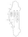
図1〜図4は本発明の実施の形態を示し、図1は車両用運転支援装置の機能ブロック図、図2は車両用運転支援装置の概略構成図、図3は運転支援制御のフローチャート、図4は設定される安全車間距離の説明図である。
【0016】
図2において、符号1は自動車等の車両であり、この車両に、先行車両との車両間隔を適切に維持できるようにドライバの運転を支援し、先行車両との衝突を防ぐ、いわゆる衝突防止機能を一つの機能として有する車両用運転支援装置2が搭載されている。以下、本発明の実施の形態では、車両用運転支援装置2の衝突防止機能の部分についてのみ説明し、他の機能の部分については説明を省略する。
【0017】
上記車両用運転支援装置2は、ステレオ光学系3で撮像した自車両の走行方向の画像から距離画像生成装置4で距離画像を生成し、この距離画像と車速センサ5で検出した自車両速度V2 を制御装置6に入力して、この制御装置6が衝突防止機能を達成すべくブザー7およびブレーキ制御装置8に制御出力するように構成されている。
【0018】
上記ステレオ光学系3は、例えば電荷結合素子(CCD)等の固体撮像素子を用いた1組のCCDカメラからなり、左右のCCDカメラが、それぞれ車室内の天井前方に一定の間隔をもって取り付けられ、車外の対象を異なる視点からステレオ撮像するようになっている。
【0019】
また、上記距離画像生成装置4は、主にイメージプロセッサで形成され、上記ステレオ光学系3で撮像した1組のステレオ画像対に対し、対応する位置のずれ量から三角測量の原理によって画像全体に渡る距離情報を求める処理を行なって、三次元の距離分布を表す距離画像を生成し上記制御装置6に入力するものである。
【0020】
上記制御装置6は、マルチマイクロプロセッサのシステムで形成され、上記距離画像生成装置4からの距離画像を処理して必要な情報を抽出するとともに、上記車速センサ5で検出した自車両速度V2 を基に、後述する運転支援制御の衝突防止制御を行ない、上記ブザー7およびブレーキ制御装置8に制御出力する。
【0021】
上記ブレーキ制御装置8は、加圧源、減圧弁、増圧弁等を備えたハイドロリックユニットで構成されたブレーキ駆動部9に接続され、このブレーキ駆動部9は上記ブレーキ制御装置8からの入力信号に応じて、タイヤのホイールシリンダ(図示せず)にブレーキ圧を導入するようになっている。
【0022】
上記制御装置6は、図1に示すように、先行車情報抽出部11、先行車速度算出部12、先行車有無判定部13、交通状態判定部14、一次安全車間距離設定部15、一次車間距離比較部16、一次出力部17、二次安全車間距離設定部18、二次車間距離比較部19、二次出力部20で主に構成されている。
【0023】
上記先行車情報抽出部11は、車間距離算出手段としての機能を有し、上記距離画像生成装置4から入力された距離画像に対して箱形パターンの特徴を抽出する等の画像処理を行ない、立体物の中から先行車両を特定し、この先行車両との距離(車間距離Ls )を上記先行車有無判定部13、一次車間距離比較部16、二次車間距離比較部19に出力する。尚、検出可能範囲内に先行車両が存在しない場合には、車間距離Ls は例えば999mのように大きな数値に設定され出力される。また、この先行車情報抽出部11では、上記車間距離Ls の時間的な変化から相対速度が算出され、上記先行車速度算出部12に出力される。
【0024】
上記先行車速度算出部12は、上記先行車情報抽出部11からの相対速度と上記車速センサ5で検出した自車両速度V2 とから先行車両の車両速度(先行車速度V1 )を算出し、上記一次安全車間距離設定部15と二次安全車間距離設定部18に出力するように形成されている。
【0025】
上記先行車有無判定部13は、上記先行車情報抽出部11からの車間距離Ls の値に基づき、先行車両があるか否かの判定を行ない、判定結果を上記交通状態判定部14と上記二次安全車間距離設定部18に出力するように形成されている。
【0026】
上記交通状態判定部14は、交通状態判定手段として形成されており、車両の交通状態を混雑状態と単独走行状態とに判定し、判定結果を上記一次安全車間距離設定部15に出力する。この交通状態判定部14では、上記一次出力部17から上記ブザー7に信号出力して警報後、あるいは、上記二次出力部20から上記ブザー7に信号出力して警報するとともに上記ブレーキ制御装置8に信号出力してブレーキ作動させた後、先行車両が設定範囲(距離L0 )内に存在する間と、先行車両が上記範囲外となって設定時間tj 経過するまでの間を混雑状態として判定し、他の交通状態を単独走行状態として判定するようになっている。
【0027】
上記一次安全車間距離設定部15は、安全車間距離設定手段として形成されており、上記交通状態判定部14からの交通状態の判定結果(混雑状態あるいは単独走行状態)に基づき、ドライバに先行車両に対する注意を促す一次支援出力の基準となる安全車間距離(一次安全車間距離LC1)を可変して算出し、上記一次車間距離比較部16に出力する。ここで、単独走行状態における一次安全車間距離L11は、先行車両の設定減速加速度をα11、自車両の設定減速加速度をα2 、自車両の操作遅れ時間をTα、停車後の余裕距離をLαとして、次式により算出する。
【0028】
また、混雑状態における一次安全車間距離L12は、次式により算出する。
【0029】
このように、上記一次安全車間距離設定部15は、上記交通状態判定部14で判定した単独走行状態か混雑状態かの交通状態に応じて、適切な一次安全車間距離LC1を設定するので、ドライバが交通状態に応じて切り換え操作する必要がない。
【0030】
上記一次車間距離比較部16は、車間距離比較手段として形成され、上記一次安全車間距離設定部15によって設定された一次安全車間距離LC1(LC1は、L11かL12のどちらか)と、現在の車間距離LS とを比較し、上記一次出力部17に信号出力するようになっている。
【0031】
上記一次出力部17は、作動信号出力手段として形成され、上記一次車間距離比較部16からの信号に基づき、車間距離LS が一次安全車間距離LC1を割り込んだ場合に、上記ブザー7を作動させるべく信号出力するとともに上記交通状態判定部14に信号出力する。
【0032】
上記二次安全車間距離設定部18は、ドライバに対して直ちに先行車両を回避するよう促すとともにブレーキをかける二次支援出力の基準となる安全車間距離(二次安全車間距離LC2)を算出し設定して、上記二次車間距離比較部19に出力するようになっている。ここで、LC2に設定される二次安全車間距離L2 は、次式によって算出する。
【0033】
上記二次車間距離比較部19は、上記二次安全車間距離設定部18によって設定された二次安全車間距離LC2(L2 )と、現在の車間距離LS とを比較し、上記二次出力部20に信号出力するとともに、上記交通状態判定部14に信号出力するようになっている。
【0034】
上記二次出力部20は、上記二次車間距離比較部19からの信号に基づき、車間距離LS が二次安全車間距離LC2を割り込んだ場合に、上記ブザー7を作動させるべく信号出力するとともにブレーキを作動させるべく上記ブレーキ制御装置8に信号出力する一方、上記交通状態判定部14に信号出力するようになっている。
【0035】
次に、上記構成によって行なわれる運転支援制御を、図3のフローチャートにより説明する。このプログラムがスタートすると、まず、ステップ(以下、「S」と略称)101で、交通状態判別フラグP,支援出力判定フラグWの各フラグとタイマカウントtcoをクリア(P=0,W=0,tco=0)し、S102で、車速センサ5から自車両速度V2 を読み込み、また、先行車情報抽出部11で車間距離Ls を、先行車速度算出部12で先行車速度V1 を算出する。
【0036】
上記交通状態判別フラグPは、単独走行状態か混雑状態かを示すフラグで、単独走行状態の場合は“0”に、混雑状態の場合は“1”にセットされる。また、上記支援出力判定フラグWは、一次支援出力あるいは二次支援出力があったか否かを示すフラグで、どちらの出力も行なっていない場合には“0”に、どちらかの出力を行なった場合には“1”にセットされる。さらに、上記タイマカウントtcoは、先行車両が設定範囲(距離L0 )内から居なくなってからの累積時間のカウント値を示す。
【0037】
上記S102の後、S103に進むと、先行車両の有無の判定、すなわち、先行車両が設定範囲(距離L0 )内に居るか否かの判定が行なわれる。この判定は、設定範囲(距離L0 )と車間距離Ls との比較により行なわれ、車間距離Ls が設定範囲(距離L0 )以下の場合(Ls ≦L0 )に先行車両が居ると判定してS103' を経てS104に進み、車間距離Ls が設定範囲(距離L0 )より大きい場合(Ls >L0 )は先行車両が居ないと判定してS115に進む。尚、このS103は、先行車有無判定部13で行なわれる処理を示す。
【0038】
上記S103' においては後述の混雑走行時に先行車が居なくなった後の累積時間tcoのクリア(tco←0)が行われる。
【0039】
上記S103の判定の結果、先行車両が居ると判定してS104に進むと、二次安全車間距離設定部18で、二次支援出力の基準となる安全車間距離(二次安全車間距離LC2)に二次安全車間距離L2 が前記(3)式により算出設定され、S105に進んで、二次車間距離比較部19で、設定された二次安全車間距離LC2と、現在の車間距離LS との比較が行なわれ、車間距離LS が二次安全車間距離LC2より大きい場合(LS >LC2)は、二次支援の段階ではないと判断してS106に進み、車間距離LS が二次安全車間距離LC2以下の場合(LS ≦LC2)は、二次支援が必要と判断してS107に進み、二次出力部20がブザー7を作動させるべく信号出力するとともにブレーキを作動させるべくブレーキ制御装置8に信号出力した後、S114に進んで支援出力判定フラグWを“1”にセット(W=1)し、前記S102に戻る。
【0040】
上記S105で、二次支援の段階ではないと判断してS106に進むと、交通状態判別フラグPがセットされているか否かの判定が行なわれ、交通状態判別フラグPがセットされている場合(P=1)は、混雑時のままであると判定してS110にジャンプし、交通状態判別フラグPがクリアされている場合(P=0)はS108に進み、支援出力判定フラグWがセットされているか否かの判定を行なう。
【0041】
上記S108で、支援出力判定フラグWがセットされている場合(W=1)は、混雑時に移行したと判定してS109に進み、交通状態判別フラグPをセット(P=1)して、S110に進む。また、上記S108で、支援出力判定フラグWがクリアされている場合(W=0)は、単独走行時のままであると判定してS111に進む。
【0042】
上記S106、S109からS110に進むと、一次安全車間距離設定部15で、一次安全車間距離LC1に混雑状態における一次安全車間距離L12が前記(2)式により算出設定され、上記S108からS111に進むと、一次安全車間距離LC1に単独走行状態における一次安全車間距離L11が前記(1)式により算出設定される。
【0043】
上記S110あるいは上記S111で一次安全車間距離LC1の設定をした後は、S112に進み、一次安全車間距離LC1と、現在の車間距離LS との比較が行なわれ、車間距離LS が一次安全車間距離LC1より大きい場合(LS >LC1)は、車間距離LS は十分適切であると判定して前記S102に戻り、車間距離LS が一次安全車間距離LC1以下の場合(LS ≦LC1)は、ドライバに注意を促すため一次支援が必要と判断してS113に進み、一次出力部17がブザー7を作動させるべく信号出力した後、S114に進んで支援出力判定フラグWを“1”にセット(W=1)し、前記S102に戻る。
【0044】
一方、前記S103で、先行車両が居ないと判定してS115に進むと、交通状態判別フラグPがクリアされているか否かの判定が行なわれ、交通状態判別フラグPがクリアされている場合(P=0)は、単独走行時のままであると判定してS102に戻り、交通状態判別フラグPがセットされている場合(P=1)は、S116に進み、1ステップの演算に要する時間Δtだけタイマカウントtcoをカウントアップする。
【0045】
その後、S117に進み、タイマカウントtcoが設定時間tj 以上になったか否か判定し、設定時間tj に満たない場合(tco<tj )は混雑時とみなしてS102に戻り、設定時間tj 以上になった場合(tco≧tj )は単独走行時に移行したと判定してS118に進んで、各フラグとタイマカウントtcoをクリア(P=0,W=0,tco=0)し、S102に戻る。
【0046】
すなわち、上記S106、S108、S109、S115〜S118で行なわれる処理が、交通状態判定部14で行なわれる処理であり、この処理によって、一次出力部17からブザー7に信号出力して警報後、あるいは、二次出力部20からブザー7に信号出力して警報するとともにブレーキ制御装置8に信号出力してブレーキ作動させた後、先行車両が設定範囲(距離L0 )内に存在する間と、先行車両が上記範囲外となって設定時間tj 経過するまでの間が混雑状態として判定され、他の交通状態が単独走行状態として判定されるのである。
【0047】
尚、本発明の実施の形態は、一次支援出力と二次支援出力とを有する二段階の装置の一次支援出力を、交通状態に応じて安全車間距離を設定することで可変にするように形成した例であるが、これに限ることなく一段階出力のみの装置にも本発明は適用できる。
【0048】
また、本発明の実施の形態で示したブザーは、警報ランプ、アナウンス等の他の手段であっても良い。
【0049】
さらに、本発明の実施の形態の二次支援出力は、ブザーへの信号出力とブレーキ制御装置への信号出力とで行なわれるように説明したが、これに限ることなく、ブザーへの信号出力のみ、ブレーキ制御装置への信号出力のみであっても良く、その他の手段、あるいはそれらの組み合わせであっても良い。
【0050】
【発明の効果】
以上説明したように本発明によれば、ドライバが操作することなく交通環境に応じて警報のタイミングが最適に設定され、先行車両との車両間隔を適切に維持できるようにドライバの運転を有効に支援することができる。
【図面の簡単な説明】
【図1】車両用運転支援装置の機能ブロック図
【図2】車両用運転支援装置の概略構成図
【図3】運転支援制御のフローチャート
【図4】設定される安全車間距離の説明図
【符号の説明】
1 車両
2 車両用運転支援装置
3 ステレオ光学系
4 距離画像生成装置
5 車速センサ
6 制御装置
7 ブザー
8 ブレーキ制御装置
11 先行車情報抽出部(車間距離算出手段)
12 先行車速度算出部
13 先行車有無判定部
14 交通状態判定部(交通状態判定手段)
15 一次安全車間距離設定部(安全車間距離設定手段)
16 一次車間距離比較部(車間距離比較手段)
17 一次出力部(作動信号出力手段)
18 二次安全車間距離設定部
19 二次車間距離比較部
20 二次出力部[0001]
BACKGROUND OF THE INVENTION
The present invention relates to a vehicle driving support device that supports driving of a driver so that a vehicle distance from a preceding vehicle can be appropriately maintained.
[0002]
[Prior art]
In recent years, in order to improve the safety of vehicles, a comprehensive driving assistance system (ADA) that actively supports driving operation of a driver has been developed. This ADA system estimates various possibilities such as a collision with a preceding vehicle and a lane departure from the traveling environment information of the vehicle and the traveling state of the host vehicle. Notifications and other controls. As a device for obtaining the traveling environment information of the vehicle, a laser / radar device or the like has been conventionally known, but recently, image information of a landscape or an object in front of the vehicle captured by a plurality of cameras mounted on the vehicle is processed. It has become possible to recognize roads and traffic environments three-dimensionally with sufficient accuracy and time for practical use.
[0003]
As one of the functions of the ADA system, there is a function of assisting the driving of the driver so as to appropriately maintain the vehicle distance from the preceding vehicle and preventing a collision with the preceding vehicle. As an example of this collision prevention device, the vehicle technology Vol.43, No.2, 1989.P.65 to P.73 “Large truck rear-end collision warning device” is detected by the vehicle speed of the host vehicle and the laser radar device. Based on the inter-vehicle distance between the subject vehicle and the preceding vehicle, a safe inter-vehicle distance is calculated, and a warning is given that there is a risk of a rear-end collision when the preceding vehicle decelerates or stops and the inter-vehicle distance interrupts the safe inter-vehicle distance. Is shown. In this prior art, the warning is set in two stages, and the driver can adjust the inter-vehicle distance by the primary warning, and can perform braking or change the course direction by the secondary warning.
[0004]
In addition, once an alarm is generated, it has the effect of raising attention, but if repeated, it may feel noisy, or there may be chronicity or habituation, so the safe inter-vehicle distance for issuing the primary alarm must be manually switched in three stages. It is possible to run on congested roads with alarms suppressed.
[0005]
[Problems to be solved by the invention]
However, when the alarm timing can be switched manually as in the prior art, when the traffic environment changes frequently, the switching operation is cumbersome and difficult to use, and as a result, the alarm is always suppressed. If the position is set, the effect may not be fully exhibited.
[0006]
The present invention has been made in view of the above circumstances, and the driving of the driver is performed so that the timing of the alarm is optimally set according to the traffic environment without the driver's operation and the vehicle distance from the preceding vehicle can be appropriately maintained. It aims at providing the driving assistance device for vehicles which supports effectively.
[0007]
[Means for Solving the Problems]
In order to achieve the above object, a driving support apparatus for a vehicle according to the present invention as set forth in
[0008]
According to a second aspect of the present invention, there is provided a vehicular driving support apparatus according to the first aspect of the present invention, wherein thesafe inter-vehicle distance setting means determines that the traffic state is another traffic state when it is determined that the congestion state is present. A safe inter-vehicle distance that is shorter than the safe inter-vehicle distance that is set in (1) is set .
[0009]
Furthermore, the vehicle driving support apparatus according to the present invention as set forth in
[0011]
That is, in the first aspect of the invention, the inter-vehicle distance calculating means calculates the inter-vehicle distance between the host vehicle and the preceding vehicle, the traffic condition determining means determines the traffic state of the vehicle, and the safe inter-vehicle distance setting means determines the vehicle Set safe inter-vehicle distance according to traffic conditions. Then, the inter-vehicle distance comparing means compares the inter-vehicle distance with the safe inter-vehicle distance and outputs a signal. Based on the signal from the inter-vehicle distance comparing means, the operating signal output means outputs an operating signal to a predetermined responding portion.At this time, the traffic state determination means determines that the preceding vehicle is within the range of the forward set distance after the responder is operated as a congested state, and the safe inter-vehicle distance setting means includes the congestion state and another traffic state. Set different safe inter-vehicle distances.
[0012]
In this case, in the invention according to
[0013]
According to a third aspect of the present invention, in thefirst aspect of the present invention, the traffic state determination means isconfigured to wait until the set time elapses when the preceding vehicle is outside the range of the forward set distance after the responding portion is actuated.Is determined as a congestion state.
[0015]
DETAILED DESCRIPTION OF THE INVENTION
Hereinafter, embodiments of the present invention will be described with reference to the drawings.
1 to 4 show an embodiment of the present invention, FIG. 1 is a functional block diagram of a vehicle driving support device, FIG. 2 is a schematic configuration diagram of the vehicle driving support device, FIG. 3 is a flowchart of driving support control, FIG. 4 is an explanatory diagram of the set safe inter-vehicle distance.
[0016]
In FIG. 2,
[0017]
The vehicle
[0018]
The stereo
[0019]
The distance image generating device 4 is formed mainly by an image processor, and applies a set of stereo images taken by the stereo
[0020]
The
[0021]
The brake control device 8 is connected to a brake drive unit 9 composed of a hydraulic unit having a pressurizing source, a pressure reducing valve, a pressure increasing valve, and the like. The brake drive unit 9 receives an input signal from the brake control device 8. Accordingly, brake pressure is introduced into a wheel cylinder (not shown) of the tire.
[0022]
As shown in FIG. 1, the
[0023]
The preceding vehicle information extraction unit 11 has a function as an inter-vehicle distance calculation unit, and performs image processing such as extracting a feature of a box pattern from a distance image input from the distance image generation device 4, The preceding vehicle is identified from the three-dimensional object, and the distance (inter-vehicle distance Ls) with the preceding vehicle is output to the preceding vehicle presence /
[0024]
The preceding vehicle
[0025]
The preceding vehicle presence /
[0026]
The traffic state determination unit 14 is formed as a traffic state determination unit, and determines the traffic state of the vehicle as a congested state or a single traveling state, and outputs the determination result to the primary safety inter-vehicle
[0027]
The primary safe inter-vehicle
[0028]
Further, the primary safety inter-vehicle distance L12 in the congested state is calculated by the following equation.
[0029]
As described above, the primary safety inter-vehicle
[0030]
The primary inter-vehicle
[0031]
The
[0032]
The secondary safety inter-vehicle
[0033]
The secondary inter-vehicle
[0034]
Based on the signal from the secondary inter-vehicle
[0035]
Next, the driving support control performed by the above configuration will be described with reference to the flowchart of FIG. When this program starts, first, in step (hereinafter abbreviated as “S”) 101, the traffic state determination flag P and the support output determination flag W and the timer count tco are cleared (P = 0, W = 0, In step S102, the host vehicle speed V2 is read from the
[0036]
The traffic state determination flag P is a flag indicating whether the vehicle is traveling alone or congested, and is set to “0” when the vehicle is traveling independently and “1” when the vehicle is congested. The support output determination flag W is a flag indicating whether or not there is a primary support output or a secondary support output. When neither output is performed, “0” is set, and when either output is performed. Is set to "1". Further, the timer count tco indicates a count value of the accumulated time after the preceding vehicle is no longer within the set range (distance L0).
[0037]
After S102, when the process proceeds to S103, it is determined whether or not there is a preceding vehicle, that is, whether or not the preceding vehicle is within the set range (distance L0). This determination is made by comparing the set range (distance L0) with the inter-vehicle distance Ls. When the inter-vehicle distance Ls is equal to or less than the set range (distance L0) (Ls≤L0), it is determined that there is a preceding vehicle and S103 ' The process proceeds to S104, and if the inter-vehicle distance Ls is larger than the set range (distance L0) (Ls> L0), it is determined that there is no preceding vehicle and the process proceeds to S115. In addition, this S103 shows the process performed in the preceding vehicle
[0038]
In S103 ′, the accumulated time tco is cleared (tco ← 0) after the preceding vehicle disappears during crowded driving described later.
[0039]
As a result of the determination of S103, when it is determined that there is a preceding vehicle and the process proceeds to S104, the secondary safe inter-vehicle
[0040]
If it is determined in S105 that it is not in the secondary support stage and the process proceeds to S106, it is determined whether or not the traffic state determination flag P is set. If the traffic state determination flag P is set ( In the case of P = 1), it is determined that the traffic is still congested, and the process jumps to S110. If the traffic state determination flag P is cleared (P = 0), the process proceeds to S108, and the support output determination flag W is set. It is determined whether or not it is.
[0041]
If the support output determination flag W is set in S108 (W = 1), it is determined that the shift has occurred at the time of congestion, and the process proceeds to S109, the traffic state determination flag P is set (P = 1), and S110 Proceed to If the support output determination flag W is cleared in S108 (W = 0), it is determined that the vehicle is still traveling independently, and the process proceeds to S111.
[0042]
When the process proceeds from S106 and S109 to S110, the primary safe inter-vehicle
[0043]
After the primary safe inter-vehicle distance LC1 is set in S110 or S111, the process proceeds to S112, where the primary safe inter-vehicle distance LC1 is compared with the current inter-vehicle distance LS, and the inter-vehicle distance LS becomes the primary safe inter-vehicle distance LC1. If it is larger (LS> LC1), it is determined that the inter-vehicle distance LS is sufficiently appropriate, and the process returns to S102. If the inter-vehicle distance LS is less than or equal to the primary safety inter-vehicle distance LC1 (LS ≤LC1), pay attention to the driver. It is determined that primary support is necessary for prompting, and the process proceeds to S113. After the
[0044]
On the other hand, if it is determined in S103 that there is no preceding vehicle and the process proceeds to S115, it is determined whether or not the traffic state determination flag P is cleared and the traffic state determination flag P is cleared ( P = 0), it is determined that the vehicle is still traveling alone, and the process returns to S102. When the traffic state determination flag P is set (P = 1), the process proceeds to S116, and the time required for one step of calculation The timer count tco is counted up by Δt.
[0045]
Thereafter, the process proceeds to S117, where it is determined whether or not the timer count tco has become equal to or greater than the set time tj. If it is determined (tco ≧ tj), it is determined that the vehicle has traveled during single traveling, and the process proceeds to S118, where each flag and timer count tco are cleared (P = 0, W = 0, tco = 0), and the process returns to S102.
[0046]
That is, the processing performed in S106, S108, S109, S115 to S118 is processing performed in the traffic state determination unit 14, and by this processing, a signal is output from the
[0047]
In the embodiment of the present invention, the primary support output of the two-stage device having the primary support output and the secondary support output is made variable by setting the safe inter-vehicle distance according to the traffic state. However, the present invention is not limited to this, and the present invention can also be applied to an apparatus having only one-stage output.
[0048]
Further, the buzzer shown in the embodiment of the present invention may be other means such as an alarm lamp or an announcement.
[0049]
Further, the secondary support output of the embodiment of the present invention has been described as being performed by the signal output to the buzzer and the signal output to the brake control device, but not limited to this, only the signal output to the buzzer Only the signal output to the brake control device may be used, or other means or a combination thereof may be used.
[0050]
【The invention's effect】
As described above, according to the present invention, the driver is effectively operated so that the warning timing is optimally set according to the traffic environment without the driver's operation, and the vehicle distance from the preceding vehicle can be appropriately maintained. Can help.
[Brief description of the drawings]
FIG. 1 is a functional block diagram of a vehicle driving support apparatus. FIG. 2 is a schematic configuration diagram of a vehicle driving support apparatus. FIG. 3 is a flowchart of driving support control. Explanation of]
DESCRIPTION OF
12 preceding vehicle
15 Primary safety inter-vehicle distance setting section (safe inter-vehicle distance setting means)
16 Primary inter-vehicle distance comparison unit (inter-vehicle distance comparison means)
17 Primary output section (actuation signal output means)
18 Secondary safety inter-vehicle
Claims (3)
Translated fromJapanese上記交通状態判定手段は、上記応動部作動後に先行車両が前方設定距離の範囲内に存在する間を混雑状態として判定し、
上記安全車間距離設定手段は、混雑状態と他の交通状態とで異なる安全車間距離を設定することを特徴とする車両用運転支援装置。Inter-vehicle distance calculating means for calculating the inter-vehicle distance between the host vehicle and the preceding vehicle, traffic state determining means for determining the traffic state of the vehicle, and safe inter-vehicle distance setting means for setting the safe inter-vehicle distance according to the traffic state of the vehicle And an inter-vehicle distance comparing means for outputting a signal by comparing the inter-vehicle distance and the safe inter-vehicle distance, and an operating signal output means for outputting an operating signal to a predetermined responding part based on a signal from the inter-vehicle distance comparing means. Prepared,
The traffic state determination means determines that the preceding vehicle is within the range of the front set distance after the responder is activated as a congested state,
The above-mentioned safe inter-vehicle distance setting means sets a different safe inter-vehicle distance in a congested state and another traffic state .
Priority Applications (4)
| Application Number | Priority Date | Filing Date | Title |
|---|---|---|---|
| JP18067796AJP3805832B2 (en) | 1996-07-10 | 1996-07-10 | Vehicle driving support device |
| US08/878,550US5850176A (en) | 1996-07-10 | 1997-06-19 | Drive assist system for vehicle |
| GB9714370AGB2315179B (en) | 1996-07-10 | 1997-07-09 | Drive assist system for vehicle |
| DE19729613ADE19729613B4 (en) | 1996-07-10 | 1997-07-10 | Driving assistance system for vehicles |
Applications Claiming Priority (1)
| Application Number | Priority Date | Filing Date | Title |
|---|---|---|---|
| JP18067796AJP3805832B2 (en) | 1996-07-10 | 1996-07-10 | Vehicle driving support device |
Publications (2)
| Publication Number | Publication Date |
|---|---|
| JPH1027300A JPH1027300A (en) | 1998-01-27 |
| JP3805832B2true JP3805832B2 (en) | 2006-08-09 |
Family
ID=16087382
Family Applications (1)
| Application Number | Title | Priority Date | Filing Date |
|---|---|---|---|
| JP18067796AExpired - LifetimeJP3805832B2 (en) | 1996-07-10 | 1996-07-10 | Vehicle driving support device |
Country Status (4)
| Country | Link |
|---|---|
| US (1) | US5850176A (en) |
| JP (1) | JP3805832B2 (en) |
| DE (1) | DE19729613B4 (en) |
| GB (1) | GB2315179B (en) |
Cited By (1)
| Publication number | Priority date | Publication date | Assignee | Title |
|---|---|---|---|---|
| CN110969895A (en)* | 2018-09-30 | 2020-04-07 | 杭州海康威视数字技术股份有限公司 | Vehicle distance detection method, device, system and server |
Families Citing this family (204)
| Publication number | Priority date | Publication date | Assignee | Title |
|---|---|---|---|---|
| US5877897A (en) | 1993-02-26 | 1999-03-02 | Donnelly Corporation | Automatic rearview mirror, vehicle lighting control and vehicle interior monitoring system using a photosensor array |
| US5910854A (en) | 1993-02-26 | 1999-06-08 | Donnelly Corporation | Electrochromic polymeric solid films, manufacturing electrochromic devices using such solid films, and processes for making such solid films and devices |
| US6822563B2 (en) | 1997-09-22 | 2004-11-23 | Donnelly Corporation | Vehicle imaging system with accessory control |
| US5670935A (en) | 1993-02-26 | 1997-09-23 | Donnelly Corporation | Rearview vision system for vehicle including panoramic view |
| US7339149B1 (en) | 1993-02-26 | 2008-03-04 | Donnelly Corporation | Vehicle headlight control using imaging sensor |
| US6396397B1 (en) | 1993-02-26 | 2002-05-28 | Donnelly Corporation | Vehicle imaging system with stereo imaging |
| US5668663A (en) | 1994-05-05 | 1997-09-16 | Donnelly Corporation | Electrochromic mirrors and devices |
| US6891563B2 (en) | 1996-05-22 | 2005-05-10 | Donnelly Corporation | Vehicular vision system |
| US7655894B2 (en) | 1996-03-25 | 2010-02-02 | Donnelly Corporation | Vehicular image sensing system |
| JP3832526B2 (en)* | 1997-06-20 | 2006-10-11 | 三菱自動車工業株式会社 | Vehicle travel control device |
| JPH1148952A (en)* | 1997-08-06 | 1999-02-23 | Mitsubishi Electric Corp | Vehicle braking system |
| US8294975B2 (en) | 1997-08-25 | 2012-10-23 | Donnelly Corporation | Automotive rearview mirror assembly |
| US6326613B1 (en) | 1998-01-07 | 2001-12-04 | Donnelly Corporation | Vehicle interior mirror assembly adapted for containing a rain sensor |
| US6172613B1 (en) | 1998-02-18 | 2001-01-09 | Donnelly Corporation | Rearview mirror assembly incorporating vehicle information display |
| US6124886A (en) | 1997-08-25 | 2000-09-26 | Donnelly Corporation | Modular rearview mirror assembly |
| US8288711B2 (en) | 1998-01-07 | 2012-10-16 | Donnelly Corporation | Interior rearview mirror system with forwardly-viewing camera and a control |
| US6445287B1 (en) | 2000-02-28 | 2002-09-03 | Donnelly Corporation | Tire inflation assistance monitoring system |
| DE19804641A1 (en)* | 1998-02-06 | 1999-08-12 | Bayerische Motoren Werke Ag | Distance-related vehicle speed control system |
| JPH11278096A (en)* | 1998-03-30 | 1999-10-12 | Nissan Motor Co Ltd | Travel control device for vehicles |
| US6477464B2 (en) | 2000-03-09 | 2002-11-05 | Donnelly Corporation | Complete mirror-based global-positioning system (GPS) navigation solution |
| US6329925B1 (en) | 1999-11-24 | 2001-12-11 | Donnelly Corporation | Rearview mirror assembly with added feature modular display |
| US6693517B2 (en) | 2000-04-21 | 2004-02-17 | Donnelly Corporation | Vehicle mirror assembly communicating wirelessly with vehicle accessories and occupants |
| DE19843395A1 (en)* | 1998-09-22 | 2000-03-23 | Volkswagen Ag | Method for speed and / or distance control in motor vehicles |
| DE19900314C2 (en)* | 1999-01-07 | 2000-10-19 | Daimler Chrysler Ag | Method and device for braking a motor vehicle in the vicinity with an obstacle |
| DE19914906A1 (en)* | 1999-04-01 | 2000-10-05 | Bosch Gmbh Robert | System for communicating between vehicles driven independently of each other includes communications devices assigned to each vehicle for exchanging signals and information |
| JP2001010373A (en)* | 1999-07-01 | 2001-01-16 | Hitachi Ltd | Car travel control device |
| JP3627582B2 (en)* | 1999-07-30 | 2005-03-09 | 日産自動車株式会社 | Vehicle tracking control device |
| JP3174833B2 (en)* | 1999-10-27 | 2001-06-11 | 建設省土木研究所長 | Right turn collision prevention system |
| DE10004527A1 (en) | 2000-02-02 | 2001-08-09 | Volkswagen Ag | Method for speed and distance control of a motor vehicle |
| US7068211B2 (en) | 2000-02-08 | 2006-06-27 | Cambridge Consultants Limited | Methods and apparatus for obtaining positional information |
| AU2001243285A1 (en) | 2000-03-02 | 2001-09-12 | Donnelly Corporation | Video mirror systems incorporating an accessory module |
| US7167796B2 (en) | 2000-03-09 | 2007-01-23 | Donnelly Corporation | Vehicle navigation system for use with a telematics system |
| US7370983B2 (en) | 2000-03-02 | 2008-05-13 | Donnelly Corporation | Interior mirror assembly with display |
| US6396408B2 (en) | 2000-03-31 | 2002-05-28 | Donnelly Corporation | Digital electrochromic circuit with a vehicle network |
| JP4823448B2 (en)* | 2000-11-24 | 2011-11-24 | トヨタ自動車株式会社 | Alarm device |
| DE60116801T2 (en)* | 2000-11-24 | 2006-08-31 | Aisin Seiki K.K., Kariya | VEHICLE COLLISION PREVENTION DEVICE |
| BR8002704U (en)* | 2000-12-01 | 2002-07-09 | Jose Raimundo Dos Santos | Provision introduced in braking system |
| JP3849430B2 (en)* | 2001-01-19 | 2006-11-22 | 日産自動車株式会社 | Vehicle travel control device |
| AU2002251807A1 (en) | 2001-01-23 | 2002-08-19 | Donnelly Corporation | Improved vehicular lighting system for a mirror assembly |
| US7255451B2 (en) | 2002-09-20 | 2007-08-14 | Donnelly Corporation | Electro-optic mirror cell |
| US7581859B2 (en) | 2005-09-14 | 2009-09-01 | Donnelly Corp. | Display device for exterior rearview mirror |
| US7697027B2 (en) | 2001-07-31 | 2010-04-13 | Donnelly Corporation | Vehicular video system |
| US6882287B2 (en) | 2001-07-31 | 2005-04-19 | Donnelly Corporation | Automotive lane change aid |
| JP3880837B2 (en)* | 2001-11-02 | 2007-02-14 | 富士重工業株式会社 | Outside monitoring device |
| US6560525B1 (en) | 2002-01-02 | 2003-05-06 | Ford Global Technologies, Llc | Integrated queue assist and adaptive cruise control |
| US6918674B2 (en) | 2002-05-03 | 2005-07-19 | Donnelly Corporation | Vehicle rearview mirror system |
| ES2391556T3 (en) | 2002-05-03 | 2012-11-27 | Donnelly Corporation | Object detection system for vehicles |
| US20060061008A1 (en) | 2004-09-14 | 2006-03-23 | Lee Karner | Mounting assembly for vehicle interior mirror |
| AU2003237424A1 (en) | 2002-06-06 | 2003-12-22 | Donnelly Corporation | Interior rearview mirror system with compass |
| US7329013B2 (en) | 2002-06-06 | 2008-02-12 | Donnelly Corporation | Interior rearview mirror system with compass |
| US6580996B1 (en)* | 2002-08-07 | 2003-06-17 | Visteon Global Technologies, Inc. | Vehicle adaptive cruise control system and method |
| US10144353B2 (en) | 2002-08-21 | 2018-12-04 | Magna Electronics Inc. | Multi-camera vision system for a vehicle |
| US7310177B2 (en) | 2002-09-20 | 2007-12-18 | Donnelly Corporation | Electro-optic reflective element assembly |
| WO2004103772A2 (en) | 2003-05-19 | 2004-12-02 | Donnelly Corporation | Mirror assembly for vehicle |
| WO2004026633A2 (en) | 2002-09-20 | 2004-04-01 | Donnelly Corporation | Mirror reflective element assembly |
| DE10251949A1 (en)* | 2002-11-08 | 2004-05-19 | Robert Bosch Gmbh | Driving dynamics regulation method in motor vehicle, involves image sensor system generating image information from vehicle's surroundings using stereo camera |
| US7446924B2 (en) | 2003-10-02 | 2008-11-04 | Donnelly Corporation | Mirror reflective element assembly including electronic component |
| US7308341B2 (en) | 2003-10-14 | 2007-12-11 | Donnelly Corporation | Vehicle communication system |
| DE10349882A1 (en)* | 2003-10-25 | 2005-05-25 | Daimlerchrysler Ag | Method for control of gap between vehicle and vehicle travelling ahead of it entails recording several load values which are multiplied together to determine set value of gap size |
| US7526103B2 (en) | 2004-04-15 | 2009-04-28 | Donnelly Corporation | Imaging system for vehicle |
| JP4379199B2 (en)* | 2004-05-17 | 2009-12-09 | 日産自動車株式会社 | Lane change support apparatus and method |
| JP4532181B2 (en)* | 2004-06-24 | 2010-08-25 | 日産自動車株式会社 | VEHICLE DRIVE OPERATION ASSISTANCE DEVICE AND VEHICLE HAVING VEHICLE DRIVE OPERATION ASSISTANCE DEVICE |
| US7881496B2 (en) | 2004-09-30 | 2011-02-01 | Donnelly Corporation | Vision system for vehicle |
| US7720580B2 (en) | 2004-12-23 | 2010-05-18 | Donnelly Corporation | Object detection system for vehicle |
| EP1883855B1 (en) | 2005-05-16 | 2011-07-20 | Donnelly Corporation | Vehicle mirror assembly with indicia at reflective element |
| EP1949666B1 (en) | 2005-11-01 | 2013-07-17 | Magna Mirrors of America, Inc. | Interior rearview mirror with display |
| CN101401024B (en) | 2006-03-09 | 2016-03-16 | 金泰克斯公司 | Comprise the vehicle rearview assembly of high intensity display |
| WO2008024639A2 (en) | 2006-08-11 | 2008-02-28 | Donnelly Corporation | Automatic headlamp control system |
| EP2122599B1 (en) | 2007-01-25 | 2019-11-13 | Magna Electronics Inc. | Radar sensing system for vehicle |
| US7914187B2 (en) | 2007-07-12 | 2011-03-29 | Magna Electronics Inc. | Automatic lighting system with adaptive alignment function |
| US8017898B2 (en) | 2007-08-17 | 2011-09-13 | Magna Electronics Inc. | Vehicular imaging system in an automatic headlamp control system |
| US7925423B2 (en)* | 2007-08-31 | 2011-04-12 | Embarq Holdings Company, Llc | System and method for traffic condition detection |
| WO2009036176A1 (en) | 2007-09-11 | 2009-03-19 | Magna Electronics | Imaging system for vehicle |
| US8446470B2 (en) | 2007-10-04 | 2013-05-21 | Magna Electronics, Inc. | Combined RGB and IR imaging sensor |
| JP5066437B2 (en)* | 2007-12-21 | 2012-11-07 | 富士重工業株式会社 | Vehicle travel control device |
| US8154418B2 (en) | 2008-03-31 | 2012-04-10 | Magna Mirrors Of America, Inc. | Interior rearview mirror system |
| DE102008023380A1 (en)* | 2008-05-13 | 2009-11-19 | GM Global Technology Operations, Inc., Detroit | Motor vehicle with a driver assistance system |
| US20100020170A1 (en) | 2008-07-24 | 2010-01-28 | Higgins-Luthman Michael J | Vehicle Imaging System |
| US9487144B2 (en) | 2008-10-16 | 2016-11-08 | Magna Mirrors Of America, Inc. | Interior mirror assembly with display |
| WO2010099416A1 (en) | 2009-02-27 | 2010-09-02 | Magna Electronics | Alert system for vehicle |
| CN102272809B (en)* | 2009-04-07 | 2014-10-08 | 三菱电机株式会社 | Vehicle short-range wireless communication device and road-to-vehicle short-range wireless communication system |
| US8376595B2 (en) | 2009-05-15 | 2013-02-19 | Magna Electronics, Inc. | Automatic headlamp control |
| CN102481874B (en) | 2009-07-27 | 2015-08-05 | 马格纳电子系统公司 | Parking assistance system |
| US9495876B2 (en) | 2009-07-27 | 2016-11-15 | Magna Electronics Inc. | Vehicular camera with on-board microcontroller |
| ES2538827T3 (en) | 2009-09-01 | 2015-06-24 | Magna Mirrors Of America, Inc. | Imaging and display system for a vehicle |
| KR101203714B1 (en)* | 2009-10-07 | 2012-11-21 | 한국전자통신연구원 | System and Method for Providing Driving Safety |
| US8890955B2 (en) | 2010-02-10 | 2014-11-18 | Magna Mirrors Of America, Inc. | Adaptable wireless vehicle vision system based on wireless communication error |
| FR2960651B1 (en)* | 2010-05-28 | 2013-08-23 | Thales Sa | METHOD FOR CORRECTING REFLECTIVITY MEASUREMENTS AND RADAR USING THE SAME |
| US9117123B2 (en) | 2010-07-05 | 2015-08-25 | Magna Electronics Inc. | Vehicular rear view camera display system with lifecheck function |
| WO2012068331A1 (en) | 2010-11-19 | 2012-05-24 | Magna Electronics Inc. | Lane keeping system and lane centering system |
| WO2012075250A1 (en) | 2010-12-01 | 2012-06-07 | Magna Electronics Inc. | System and method of establishing a multi-camera image using pixel remapping |
| US9264672B2 (en) | 2010-12-22 | 2016-02-16 | Magna Mirrors Of America, Inc. | Vision display system for vehicle |
| US8972147B2 (en) | 2011-01-10 | 2015-03-03 | Bendix Commercial Vehicle Systems Llc | ACC and AM braking range variable based on internal and external factors |
| US9085261B2 (en) | 2011-01-26 | 2015-07-21 | Magna Electronics Inc. | Rear vision system with trailer angle detection |
| US8902054B2 (en) | 2011-02-10 | 2014-12-02 | Sitting Man, Llc | Methods, systems, and computer program products for managing operation of a portable electronic device |
| US8666603B2 (en) | 2011-02-11 | 2014-03-04 | Sitting Man, Llc | Methods, systems, and computer program products for providing steering-control feedback to an operator of an automotive vehicle |
| US8773251B2 (en) | 2011-02-10 | 2014-07-08 | Sitting Man, Llc | Methods, systems, and computer program products for managing operation of an automotive vehicle |
| US11145215B1 (en) | 2011-03-11 | 2021-10-12 | Sitting Man, Llc | Methods, systems, and computer program products for providing feedback to a user of a portable electronic in motion |
| US9194943B2 (en) | 2011-04-12 | 2015-11-24 | Magna Electronics Inc. | Step filter for estimating distance in a time-of-flight ranging system |
| WO2012145819A1 (en) | 2011-04-25 | 2012-11-01 | Magna International Inc. | Image processing method for detecting objects using relative motion |
| US9834153B2 (en) | 2011-04-25 | 2017-12-05 | Magna Electronics Inc. | Method and system for dynamically calibrating vehicular cameras |
| US9357208B2 (en) | 2011-04-25 | 2016-05-31 | Magna Electronics Inc. | Method and system for dynamically calibrating vehicular cameras |
| US10793067B2 (en) | 2011-07-26 | 2020-10-06 | Magna Electronics Inc. | Imaging system for vehicle |
| WO2013019707A1 (en) | 2011-08-01 | 2013-02-07 | Magna Electronics Inc. | Vehicle camera alignment system |
| US20140218535A1 (en) | 2011-09-21 | 2014-08-07 | Magna Electronics Inc. | Vehicle vision system using image data transmission and power supply via a coaxial cable |
| US9681062B2 (en) | 2011-09-26 | 2017-06-13 | Magna Electronics Inc. | Vehicle camera image quality improvement in poor visibility conditions by contrast amplification |
| US9146898B2 (en) | 2011-10-27 | 2015-09-29 | Magna Electronics Inc. | Driver assist system with algorithm switching |
| US9491451B2 (en) | 2011-11-15 | 2016-11-08 | Magna Electronics Inc. | Calibration system and method for vehicular surround vision system |
| US10099614B2 (en) | 2011-11-28 | 2018-10-16 | Magna Electronics Inc. | Vision system for vehicle |
| WO2013086249A2 (en) | 2011-12-09 | 2013-06-13 | Magna Electronics, Inc. | Vehicle vision system with customized display |
| DE102012100698B4 (en)* | 2012-01-30 | 2025-09-11 | Conti Temic Microelectronic Gmbh | Method and driver assistance system for detecting fatigue and/or assessing driver attention |
| US10457209B2 (en) | 2012-02-22 | 2019-10-29 | Magna Electronics Inc. | Vehicle vision system with multi-paned view |
| WO2013126715A2 (en) | 2012-02-22 | 2013-08-29 | Magna Electronics, Inc. | Vehicle camera system with image manipulation |
| US8694224B2 (en) | 2012-03-01 | 2014-04-08 | Magna Electronics Inc. | Vehicle yaw rate correction |
| US10609335B2 (en) | 2012-03-23 | 2020-03-31 | Magna Electronics Inc. | Vehicle vision system with accelerated object confirmation |
| US9751465B2 (en) | 2012-04-16 | 2017-09-05 | Magna Electronics Inc. | Vehicle vision system with reduced image color data processing by use of dithering |
| US8879139B2 (en) | 2012-04-24 | 2014-11-04 | Gentex Corporation | Display mirror assembly |
| US10089537B2 (en) | 2012-05-18 | 2018-10-02 | Magna Electronics Inc. | Vehicle vision system with front and rear camera integration |
| US9340227B2 (en) | 2012-08-14 | 2016-05-17 | Magna Electronics Inc. | Vehicle lane keep assist system |
| DE102013217430A1 (en) | 2012-09-04 | 2014-03-06 | Magna Electronics, Inc. | Driver assistance system for a motor vehicle |
| US9558409B2 (en) | 2012-09-26 | 2017-01-31 | Magna Electronics Inc. | Vehicle vision system with trailer angle detection |
| US9446713B2 (en) | 2012-09-26 | 2016-09-20 | Magna Electronics Inc. | Trailer angle detection system |
| US9723272B2 (en) | 2012-10-05 | 2017-08-01 | Magna Electronics Inc. | Multi-camera image stitching calibration system |
| US9090234B2 (en) | 2012-11-19 | 2015-07-28 | Magna Electronics Inc. | Braking control system for vehicle |
| US9743002B2 (en) | 2012-11-19 | 2017-08-22 | Magna Electronics Inc. | Vehicle vision system with enhanced display functions |
| US10025994B2 (en) | 2012-12-04 | 2018-07-17 | Magna Electronics Inc. | Vehicle vision system utilizing corner detection |
| US9481301B2 (en) | 2012-12-05 | 2016-11-01 | Magna Electronics Inc. | Vehicle vision system utilizing camera synchronization |
| US20140168415A1 (en) | 2012-12-07 | 2014-06-19 | Magna Electronics Inc. | Vehicle vision system with micro lens array |
| US9092986B2 (en) | 2013-02-04 | 2015-07-28 | Magna Electronics Inc. | Vehicular vision system |
| US20140218529A1 (en) | 2013-02-04 | 2014-08-07 | Magna Electronics Inc. | Vehicle data recording system |
| US10179543B2 (en) | 2013-02-27 | 2019-01-15 | Magna Electronics Inc. | Multi-camera dynamic top view vision system |
| US9688200B2 (en) | 2013-03-04 | 2017-06-27 | Magna Electronics Inc. | Calibration system and method for multi-camera vision system |
| KR101881346B1 (en) | 2013-03-15 | 2018-07-24 | 젠텍스 코포레이션 | Display mirror assembly |
| US10027930B2 (en) | 2013-03-29 | 2018-07-17 | Magna Electronics Inc. | Spectral filtering for vehicular driver assistance systems |
| US9327693B2 (en) | 2013-04-10 | 2016-05-03 | Magna Electronics Inc. | Rear collision avoidance system for vehicle |
| US10232797B2 (en) | 2013-04-29 | 2019-03-19 | Magna Electronics Inc. | Rear vision system for vehicle with dual purpose signal lines |
| US9508014B2 (en) | 2013-05-06 | 2016-11-29 | Magna Electronics Inc. | Vehicular multi-camera vision system |
| US9205776B2 (en) | 2013-05-21 | 2015-12-08 | Magna Electronics Inc. | Vehicle vision system using kinematic model of vehicle motion |
| US9563951B2 (en) | 2013-05-21 | 2017-02-07 | Magna Electronics Inc. | Vehicle vision system with targetless camera calibration |
| US10567705B2 (en) | 2013-06-10 | 2020-02-18 | Magna Electronics Inc. | Coaxial cable with bidirectional data transmission |
| DE102013211427B4 (en) | 2013-06-18 | 2016-10-13 | Continental Automotive Gmbh | Method and device for determining a driving state of an external motor vehicle |
| US9260095B2 (en) | 2013-06-19 | 2016-02-16 | Magna Electronics Inc. | Vehicle vision system with collision mitigation |
| US20140375476A1 (en) | 2013-06-24 | 2014-12-25 | Magna Electronics Inc. | Vehicle alert system |
| US10755110B2 (en) | 2013-06-28 | 2020-08-25 | Magna Electronics Inc. | Trailering assist system for vehicle |
| US10326969B2 (en) | 2013-08-12 | 2019-06-18 | Magna Electronics Inc. | Vehicle vision system with reduction of temporal noise in images |
| US9619716B2 (en) | 2013-08-12 | 2017-04-11 | Magna Electronics Inc. | Vehicle vision system with image classification |
| JP2016534915A (en) | 2013-09-24 | 2016-11-10 | ジェンテックス コーポレイション | Display mirror assembly |
| JP5914593B2 (en) | 2013-10-01 | 2016-05-11 | 富士重工業株式会社 | Vehicle seat airbag system and vehicle seat |
| US10529237B2 (en)* | 2013-11-25 | 2020-01-07 | Toyota Jidosha Kabushiki Kaisha | Collision-avoidance support device |
| US9499139B2 (en) | 2013-12-05 | 2016-11-22 | Magna Electronics Inc. | Vehicle monitoring system |
| US9988047B2 (en) | 2013-12-12 | 2018-06-05 | Magna Electronics Inc. | Vehicle control system with traffic driving control |
| US9511715B2 (en) | 2014-01-31 | 2016-12-06 | Gentex Corporation | Backlighting assembly for display for reducing cross-hatching |
| US10160382B2 (en) | 2014-02-04 | 2018-12-25 | Magna Electronics Inc. | Trailer backup assist system |
| US10705332B2 (en) | 2014-03-21 | 2020-07-07 | Gentex Corporation | Tri-modal display mirror assembly |
| KR101894262B1 (en) | 2014-04-01 | 2018-09-04 | 젠텍스 코포레이션 | Automatic display mirror assembly |
| US9623878B2 (en) | 2014-04-02 | 2017-04-18 | Magna Electronics Inc. | Personalized driver assistance system for vehicle |
| US9487235B2 (en) | 2014-04-10 | 2016-11-08 | Magna Electronics Inc. | Vehicle control system with adaptive wheel angle correction |
| JP2016001464A (en)* | 2014-05-19 | 2016-01-07 | 株式会社リコー | Processor, processing system, processing program, and processing method |
| US10328932B2 (en) | 2014-06-02 | 2019-06-25 | Magna Electronics Inc. | Parking assist system with annotated map generation |
| US9925980B2 (en) | 2014-09-17 | 2018-03-27 | Magna Electronics Inc. | Vehicle collision avoidance system with enhanced pedestrian avoidance |
| US9694751B2 (en) | 2014-09-19 | 2017-07-04 | Gentex Corporation | Rearview assembly |
| WO2016073848A1 (en) | 2014-11-07 | 2016-05-12 | Gentex Corporation | Full display mirror actuator |
| US10071689B2 (en) | 2014-11-13 | 2018-09-11 | Gentex Corporation | Rearview mirror system with a display |
| US10131279B2 (en) | 2014-12-03 | 2018-11-20 | Gentex Corporation | Display mirror assembly with an RF shield bezel |
| USD746744S1 (en) | 2014-12-05 | 2016-01-05 | Gentex Corporation | Rearview device |
| US9744907B2 (en) | 2014-12-29 | 2017-08-29 | Gentex Corporation | Vehicle vision system having adjustable displayed field of view |
| US9916660B2 (en) | 2015-01-16 | 2018-03-13 | Magna Electronics Inc. | Vehicle vision system with calibration algorithm |
| US9720278B2 (en) | 2015-01-22 | 2017-08-01 | Gentex Corporation | Low cost optical film stack |
| US10286855B2 (en) | 2015-03-23 | 2019-05-14 | Magna Electronics Inc. | Vehicle vision system with video compression |
| JP2018513810A (en) | 2015-04-20 | 2018-05-31 | ジェンテックス コーポレイション | Rear view assembly with decoration |
| US10946799B2 (en) | 2015-04-21 | 2021-03-16 | Magna Electronics Inc. | Vehicle vision system with overlay calibration |
| US10819943B2 (en) | 2015-05-07 | 2020-10-27 | Magna Electronics Inc. | Vehicle vision system with incident recording function |
| EP3297870B1 (en) | 2015-05-18 | 2020-02-05 | Gentex Corporation | Full display rearview device |
| WO2016209877A1 (en) | 2015-06-22 | 2016-12-29 | Gentex Corporation | System and method for processing streamed video images to correct for flicker of amplitude-modulated lights |
| US10214206B2 (en) | 2015-07-13 | 2019-02-26 | Magna Electronics Inc. | Parking assist system for vehicle |
| US10078789B2 (en) | 2015-07-17 | 2018-09-18 | Magna Electronics Inc. | Vehicle parking assist system with vision-based parking space detection |
| US10086870B2 (en) | 2015-08-18 | 2018-10-02 | Magna Electronics Inc. | Trailer parking assist system for vehicle |
| US10875403B2 (en) | 2015-10-27 | 2020-12-29 | Magna Electronics Inc. | Vehicle vision system with enhanced night vision |
| WO2017075420A1 (en) | 2015-10-30 | 2017-05-04 | Gentex Corporation | Toggle paddle |
| USD797627S1 (en) | 2015-10-30 | 2017-09-19 | Gentex Corporation | Rearview mirror device |
| CN108349436B (en) | 2015-10-30 | 2019-12-20 | 金泰克斯公司 | Rear-view device |
| USD798207S1 (en) | 2015-10-30 | 2017-09-26 | Gentex Corporation | Rearview mirror assembly |
| USD800618S1 (en) | 2015-11-02 | 2017-10-24 | Gentex Corporation | Toggle paddle for a rear view device |
| US10144419B2 (en) | 2015-11-23 | 2018-12-04 | Magna Electronics Inc. | Vehicle dynamic control system for emergency handling |
| US11285878B2 (en) | 2015-12-17 | 2022-03-29 | Magna Electronics Inc. | Vehicle vision system with camera line power filter |
| US11277558B2 (en) | 2016-02-01 | 2022-03-15 | Magna Electronics Inc. | Vehicle vision system with master-slave camera configuration |
| US11433809B2 (en) | 2016-02-02 | 2022-09-06 | Magna Electronics Inc. | Vehicle vision system with smart camera video output |
| US10160437B2 (en) | 2016-02-29 | 2018-12-25 | Magna Electronics Inc. | Vehicle control system with reverse assist |
| US20170253237A1 (en) | 2016-03-02 | 2017-09-07 | Magna Electronics Inc. | Vehicle vision system with automatic parking function |
| US10132971B2 (en) | 2016-03-04 | 2018-11-20 | Magna Electronics Inc. | Vehicle camera with multiple spectral filters |
| US10055651B2 (en) | 2016-03-08 | 2018-08-21 | Magna Electronics Inc. | Vehicle vision system with enhanced lane tracking |
| USD845851S1 (en) | 2016-03-31 | 2019-04-16 | Gentex Corporation | Rearview device |
| USD817238S1 (en) | 2016-04-29 | 2018-05-08 | Gentex Corporation | Rearview device |
| US10025138B2 (en) | 2016-06-06 | 2018-07-17 | Gentex Corporation | Illuminating display with light gathering structure |
| US10300859B2 (en) | 2016-06-10 | 2019-05-28 | Magna Electronics Inc. | Multi-sensor interior mirror device with image adjustment |
| USD809984S1 (en) | 2016-12-07 | 2018-02-13 | Gentex Corporation | Rearview assembly |
| USD854473S1 (en) | 2016-12-16 | 2019-07-23 | Gentex Corporation | Rearview assembly |
| KR20190104990A (en) | 2016-12-30 | 2019-09-11 | 젠텍스 코포레이션 | Full display mirror with instant custom spotter view |
| EP3595931A4 (en) | 2017-03-17 | 2020-01-22 | Gentex Corporation | REVIEW REVERSE CAMERA WITH TWO |
| CN107600070B (en)* | 2017-08-30 | 2019-12-13 | 北京新能源汽车股份有限公司 | Control method and device of automatic emergency braking system, controller and automobile |
| FR3100514B1 (en)* | 2019-09-05 | 2022-12-02 | Renault Sas | Method for managing a safety distance. |
| DE102019218168A1 (en)* | 2019-11-25 | 2021-05-27 | Volkswagen Aktiengesellschaft | Method, computer program and device for providing information on a safety distance for a motor vehicle |
| US11968639B2 (en) | 2020-11-11 | 2024-04-23 | Magna Electronics Inc. | Vehicular control system with synchronized communication between control units |
| US11994272B2 (en) | 2021-08-20 | 2024-05-28 | Gentex Corporation | Lighting assembly and illumination system having a lighting assembly |
Family Cites Families (11)
| Publication number | Priority date | Publication date | Assignee | Title |
|---|---|---|---|---|
| US4028662A (en)* | 1976-05-24 | 1977-06-07 | Raymond Donald Young | Passing vehicle signalling apparatus |
| US5014200A (en)* | 1990-02-20 | 1991-05-07 | General Motors Corporation | Adaptive cruise system |
| US5309137A (en)* | 1991-02-26 | 1994-05-03 | Mitsubishi Denki Kabushiki Kaisha | Motor car traveling control device |
| JPH0672297A (en)* | 1992-08-25 | 1994-03-15 | Fuji Heavy Ind Ltd | Control method of automatic brake device |
| US5459460A (en)* | 1992-12-11 | 1995-10-17 | Kansei Corporation | Collision warning system |
| JP3079881B2 (en)* | 1993-08-10 | 2000-08-21 | 三菱自動車工業株式会社 | Road traffic condition estimation method and vehicle driving characteristic control method |
| DE4335979A1 (en)* | 1993-10-21 | 1995-04-27 | Telefunken Microelectron | Security management system (SMS) |
| JPH07251651A (en)* | 1994-03-15 | 1995-10-03 | Nissan Motor Co Ltd | Inter-vehicle distance control device |
| US5631639A (en)* | 1994-04-20 | 1997-05-20 | Nippondenso Co., Ltd. | Collision alarm system for automotive vehicle |
| DE4437678B4 (en)* | 1994-10-21 | 2007-07-05 | Conti Temic Microelectronic Gmbh | Method for adjusting the distance of motor vehicles |
| US5805103A (en)* | 1995-09-27 | 1998-09-08 | Mazda Motor Corporation | Method of and system for monitoring preceding vehicles |
- 1996
- 1996-07-10JPJP18067796Apatent/JP3805832B2/ennot_activeExpired - Lifetime
- 1997
- 1997-06-19USUS08/878,550patent/US5850176A/ennot_activeExpired - Lifetime
- 1997-07-09GBGB9714370Apatent/GB2315179B/ennot_activeExpired - Fee Related
- 1997-07-10DEDE19729613Apatent/DE19729613B4/ennot_activeExpired - Fee Related
Cited By (1)
| Publication number | Priority date | Publication date | Assignee | Title |
|---|---|---|---|---|
| CN110969895A (en)* | 2018-09-30 | 2020-04-07 | 杭州海康威视数字技术股份有限公司 | Vehicle distance detection method, device, system and server |
Also Published As
| Publication number | Publication date |
|---|---|
| JPH1027300A (en) | 1998-01-27 |
| US5850176A (en) | 1998-12-15 |
| GB2315179B (en) | 2001-03-21 |
| DE19729613B4 (en) | 2005-11-10 |
| GB9714370D0 (en) | 1997-09-10 |
| DE19729613A1 (en) | 1998-01-22 |
| GB2315179A (en) | 1998-01-21 |
Similar Documents
| Publication | Publication Date | Title |
|---|---|---|
| JP3805832B2 (en) | Vehicle driving support device | |
| JP3726923B2 (en) | Vehicle driving support device | |
| JP3358709B2 (en) | Driving support device for vehicles | |
| JP5375752B2 (en) | Vehicle driving support device | |
| JP3866349B2 (en) | Vehicle collision prevention device | |
| KR101884159B1 (en) | Driving control method and driving control device | |
| JP6530705B2 (en) | Driving support device and driving support method | |
| JP2021020497A (en) | Collision avoidance support device | |
| CN103359113B (en) | Driving auxiliary device for vehicle | |
| JPH08205306A (en) | Alarm device for car | |
| JP2020097346A (en) | Vehicle running control device | |
| JP2001093099A (en) | Driving support device for vehicles | |
| JP6654907B2 (en) | Vehicle travel control device | |
| CN109388137B (en) | Driving assistance apparatus and storage medium | |
| JP4204830B2 (en) | Vehicle driving support device | |
| JP7708560B2 (en) | Driving Support Devices | |
| JP3720117B2 (en) | Vehicle alarm device | |
| JP3972659B2 (en) | Rear side warning device for vehicles | |
| JP3747617B2 (en) | Brake assist system | |
| JP4628596B2 (en) | Vehicle driving support device | |
| JP6611737B2 (en) | Method for carrying out a braking process by a vehicle brake assistant | |
| JP3400391B2 (en) | Inter-vehicle distance alarm device | |
| JP2023083081A (en) | vehicle controller | |
| JP3730616B2 (en) | Vehicle driving support device | |
| JP4163074B2 (en) | Vehicle driving support device |
Legal Events
| Date | Code | Title | Description |
|---|---|---|---|
| A977 | Report on retrieval | Free format text:JAPANESE INTERMEDIATE CODE: A971007 Effective date:20050419 | |
| A131 | Notification of reasons for refusal | Free format text:JAPANESE INTERMEDIATE CODE: A131 Effective date:20050426 | |
| A521 | Written amendment | Free format text:JAPANESE INTERMEDIATE CODE: A523 Effective date:20050602 | |
| TRDD | Decision of grant or rejection written | ||
| A01 | Written decision to grant a patent or to grant a registration (utility model) | Free format text:JAPANESE INTERMEDIATE CODE: A01 Effective date:20060502 | |
| A61 | First payment of annual fees (during grant procedure) | Free format text:JAPANESE INTERMEDIATE CODE: A61 Effective date:20060511 | |
| R150 | Certificate of patent or registration of utility model | Free format text:JAPANESE INTERMEDIATE CODE: R150 | |
| FPAY | Renewal fee payment (event date is renewal date of database) | Free format text:PAYMENT UNTIL: 20090519 Year of fee payment:3 | |
| FPAY | Renewal fee payment (event date is renewal date of database) | Free format text:PAYMENT UNTIL: 20100519 Year of fee payment:4 | |
| FPAY | Renewal fee payment (event date is renewal date of database) | Free format text:PAYMENT UNTIL: 20110519 Year of fee payment:5 | |
| FPAY | Renewal fee payment (event date is renewal date of database) | Free format text:PAYMENT UNTIL: 20110519 Year of fee payment:5 | |
| FPAY | Renewal fee payment (event date is renewal date of database) | Free format text:PAYMENT UNTIL: 20120519 Year of fee payment:6 | |
| FPAY | Renewal fee payment (event date is renewal date of database) | Free format text:PAYMENT UNTIL: 20130519 Year of fee payment:7 | |
| FPAY | Renewal fee payment (event date is renewal date of database) | Free format text:PAYMENT UNTIL: 20140519 Year of fee payment:8 | |
| R250 | Receipt of annual fees | Free format text:JAPANESE INTERMEDIATE CODE: R250 | |
| S531 | Written request for registration of change of domicile | Free format text:JAPANESE INTERMEDIATE CODE: R313531 | |
| R350 | Written notification of registration of transfer | Free format text:JAPANESE INTERMEDIATE CODE: R350 | |
| R250 | Receipt of annual fees | Free format text:JAPANESE INTERMEDIATE CODE: R250 | |
| R250 | Receipt of annual fees | Free format text:JAPANESE INTERMEDIATE CODE: R250 | |
| EXPY | Cancellation because of completion of term |