JP3805542B2 - Card feeding device and feeding method - Google Patents
Card feeding device and feeding methodDownload PDFInfo
- Publication number
- JP3805542B2 JP3805542B2JP32074398AJP32074398AJP3805542B2JP 3805542 B2JP3805542 B2JP 3805542B2JP 32074398 AJP32074398 AJP 32074398AJP 32074398 AJP32074398 AJP 32074398AJP 3805542 B2JP3805542 B2JP 3805542B2
- Authority
- JP
- Japan
- Prior art keywords
- card
- hopper
- suction pad
- suction
- feeding
- Prior art date
- Legal status (The legal status is an assumption and is not a legal conclusion. Google has not performed a legal analysis and makes no representation as to the accuracy of the status listed.)
- Expired - Fee Related
Links
- 238000000034methodMethods0.000titleclaimsdescription14
- 230000033001locomotionEffects0.000claimsdescription17
- 230000005489elastic deformationEffects0.000claimsdescription10
- 238000012840feeding operationMethods0.000claimsdescription9
- 238000000926separation methodMethods0.000claimsdescription7
- 238000007664blowingMethods0.000claims1
- 230000007246mechanismEffects0.000description13
- 238000004806packaging method and processMethods0.000description9
- 238000009825accumulationMethods0.000description8
- 239000012785packaging filmSubstances0.000description8
- 229920006280packaging filmPolymers0.000description8
- 238000010586diagramMethods0.000description5
- 230000008569processEffects0.000description3
- 230000005540biological transmissionEffects0.000description2
- 238000005096rolling processMethods0.000description2
- 230000009471actionEffects0.000description1
- 230000008878couplingEffects0.000description1
- 238000010168coupling processMethods0.000description1
- 238000005859coupling reactionMethods0.000description1
- 238000001514detection methodMethods0.000description1
- 230000000694effectsEffects0.000description1
- 230000002452interceptive effectEffects0.000description1
- 238000012986modificationMethods0.000description1
- 230000004048modificationEffects0.000description1
- 230000002093peripheral effectEffects0.000description1
- 239000004033plasticSubstances0.000description1
- 238000007789sealingMethods0.000description1
- 230000032258transportEffects0.000description1
- 238000004804windingMethods0.000description1
Images


Landscapes
- Credit Cards Or The Like (AREA)
- Sheets, Magazines, And Separation Thereof (AREA)
- Conveying Record Carriers (AREA)
Description
Translated fromJapanese【0001】
【発明の属する技術分野】
本発明は、ホッパ内に積層して収容された可撓性のカードをその最下位のカードから1枚ずつ繰り出すカードの繰出し装置及びその繰出し方法に関する。
【0002】
【関連する背景技術】
この種のカードの繰出し装置には、ホッパ内の最上位のカードから順次1枚ずつ繰り出す上面繰出し方式、逆に、その最下位のカードから順次1枚ずつ繰り出す下面繰出し方式の何れかが採用されている。上面繰出し方式はその1枚当たりの重量が比較的重くなる大判のカードの繰出しに好適し、これに対し、プリペイドカードのような小判のカードの繰出しにはホッパ内への補充の容易さから、一般的に下面繰出し方式が採用されている。
【0003】
下面繰出し方式にあっては、ホッパ内の最下位のカードに収容されているカード全体の重量が加わり、しかも、プリペイドカードは表裏ともに平滑であるため、最下位のカードとその次のカードとが強力に密着し易い。このため、ホッパから最下位のカードを繰り出す際、最下位のカードとともに次のカードもまた繰り出されてしまうことがある。
【0004】
このようなカードの2枚繰出しを防止するため、例えば特開平3-102034号公報のカード繰出し装置が知られている。この公知のカード繰出し装置は、ホッパの下方に吸着パッドに加えて単一のローラを備えており、ホッパ内の最下位のカードはその中央にて、そのローラに支持され、そして、吸着パッドはそのカードの一端部を吸着して下降する。ここで、カードの中央部分はローラにより、その下降が阻止されているから、吸着パッドの下降はカードの一端部を円弧状に弾性変形させ、この弾性変形を利用して、吸着した最下位のカードと次のカードとの分離が達成される。
【0005】
【発明が解決しようとする課題】
しかしながら、プリペイドカード等のプラスチックからなるカードは可撓性に優れ、特にその長手方向に関しては容易に弾性変形する。このため、次のカードが最下位のカードと同様に弾性変形する際、その弾性変形により発生する復元力は弱く、この復元力に対して最下位のカードと次のカードとの間の密着力が打ち勝つことがある。この場合には、次のカードもまた最下位のカードと同様に弾性変形して、これら2枚のカードが同時に繰り出されてしまうことにもなり、カードの1枚繰出しを確実に達成することができない。
【0006】
本発明は上述の事情に基づいてなされたもので、その目的とするところは、ホッパからカードを1枚ずつ確実に繰り出すことができるカードの繰出し装置及びその繰出し方法を提供することにある。
【0007】
【課題を解決するための手段】
本発明のカードの繰出し方法を実施する装置は、下向きのホッパ出口を有したホッパと、ホッパ出口の下方に配置された吸着パッドとを備えており、この吸着パッドにはパッド駆動手段により、ホッパ出口に対する上下の接離運動と水平方向の進退運動とを組み合わせたカードの繰出し動作が与えられる。
【0008】
カードの繰出し装置(請求項1)は、ホッパ出口の下方にて、吸着パッドの両側に配置された一対の支持ローラを更に備えており、これら支持ローラは吸着パッドの進退方向に延びている。各支持ローラはローラ駆動手段により、ホッパ出口直下の位置した作動位置と、この作動位置よりも下方の退避位置との間にて往復移動される。
【0009】
吸着パッドによるカードの繰出し動作により、ホッパ内の最下位のカードが吸着パッドに吸着されるとき、一対の支持ローラは作動位置にあり、吸着パッドの両側にて最下位のカードの両側部分を支持している。このような状態にて、吸着パッドの繰出し動作が進み、吸着した最下位のカードを伴い、吸着パッドが下降すると、最下位のカードはその吸着パッドの両側部分が一対の支持ローラにより支持されているので、その両側部分の下降は拘束された状態にある。このため、最下位のカードは、支持ローラ間の中央部分のみが吸着パッドにより引き出され、U字形に弾性変形する(請求項4)、この後、一対の支持ローラは作動位置から退避位置に移動して、最下位のカードの拘束を解放し、これにより、最下位のカードの繰出しが完了する。
【0010】
カードの繰り出しの際、ホッパ内の次のカードと最下位のカードとの間の密着力が強いと、次のカードは最下位のカードと同様にU字形に弾性変形しようとする。しかしながら、これらカードの弾性変形は支持ローラ間の狭い領域のみに限定されるので、これら弾性変形により発生する復元力はその密着力に十分に打ち勝つ程度に大となる。この結果、吸着パッドに吸着された最下位のカードのみがその弾性変形を維持することができ、この弾性変形は最下位のカードとホッパ内の次のカードとの間に貫通通路を作り出し、最下位のカードを次のカードから分離する。
【0011】
好ましくは、一対の支持ローラは作動位置と退避位置との間を円弧経路に沿って往復移動する(請求項2)。このような支持ローラの円弧の往復移動は支持ローラとホッパ出口との間の干渉を避け、且つ、繰り出されるカードの拘束を速やかに解放する。
更に、カードの繰出し装置は、カードの繰出しの際、一対の支持ローラ間に吸着パッドの後退方向に沿って圧縮空気を吹き出すエアノズルを更に含んでいる(請求項3)。この場合、エアノズルは、最下位のカードがU字形に弾性変形して前記貫通通路が形成されると、この貫通通路内に向けて圧縮空気を噴出する。噴出された圧縮空気は貫通通路内を流れ、最下位のカードと次のカードとの分離を促進する。
【0012】
【発明の実施の形態】
図1はカード集積包装機内でのカードの集積から、その集積包装までの一連の流れを概略的に示している。カード集積包装機は先ず、カード繰出し装置2を備えており、カード繰出し装置2は選択された1つのホッパからカードCを1枚ずつ繰り出す。繰り出されたカードCは集積セクション4に移送され、この集積セクション4にて、カードCは所定の枚数毎の集積カードSに集積され、そして、集積カードSは集積セクション4から包装ライン6の始端近傍に規定された供給位置に移送される。
【0013】
包装ライン6はその始端にターレット8を備え、ターレット8と供給位置との間に包装フィルムFの垂下ラインが確保されている。包装フィルムFはフィルムロールFRから垂下ラインに繰り出されたフィルムウエブFWを所定の長さに切断して得られる。なお、フィルムウエブFWの繰出し中、フィルムウエブFWにはティアテープTが貼り付けられるようになっており、ティアテープTはテープロールTRから繰り出される。
【0014】
集積カードSは包装フィルムFとともにターレット8のポケットに挿入され、この際、包装フィルムFは集積カードSの回りに胴折りされる。この後、ターレット8の回転に伴い、包装フィルムFの胴フラップ折り及び胴シールを経て、集積カードSは包装フィルムFに筒状に包み込まれ、ターレット8のポケットから包装ラインの耳折りセクションに排出される。耳折りセクション内を移送される過程にて、包装フィルムFの左右の耳折りを経てサイドシールが実施され、包装フィルムFによる集積カードSの包装が完了し、包装品Hが得られる。
【0015】
この後、包装品HにはラベルLが貼り付けられ、そして、包装品Hはこれら包装品Hを積層状態にして移送する排出セクション10に排出される。なお、ラベルLは、ラベルロールLRから繰り出されるラベルウエブLWを所定の長さに切断して得られ、ラベルウエブLWの繰出し経路中には、ラベルウエブLWに所定の情報を印刷するプリンタ12が配置されている。
【0016】
次に、前述したカード繰出し装置2に関して詳細に説明する。
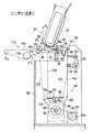
図2を参照すると、カード繰出し装置2はホッパ20を有し、ホッパ20は図1から明らかなように複数個備えられている。各ホッパ20は中空の角柱状をなし、その横断面でみて長辺側が前述のカード繰出し方向に沿い、そして、その背面がホッパホルダ22に傾斜した状態で支持されている。なお、ホッパ20の傾斜角αは約20°に設定されている。
【0017】
ホッパホルダ22は、前述した包装ラインに対して直交する水平方向に延びており、この水平方向に各ホッパ20は等間隔を存して一列に配置されている。ホッパホルダ22は図示しない往復移動機構により、ホッパ20の配列方向に往復移動可能であり、これにより、選択した1つのホッパ20がカード繰出し位置に位置付けられるようになっている。
【0018】
各ホッパ20内にはプリペイドカード等の可撓性を有したカードCがその上面を上向きにした状態で積層して収容されている。それ故、ホッパ20内のカードCの積層体はホッパ20の傾斜に従い、その各々のカードCはその短辺側となる前端が持ち上がった状態で傾斜している。更に詳述すれば、ホッパ20のホッパ出口にはその両側縁にロッド状の底部材24を有し、積層体はカードCの長辺側となる両側縁のみが左右の底部材24に支持されている。
【0019】
カード繰出し位置にあるホッパ20(以下、単にホッパ20として参照する)の下方には一対の吸着パッド26が上向きに配置されている。これら吸着パッド26はパッドホルダ28に取り付けられ、ホッパ20の側面に沿う方向、即ち、カード繰出し方向に離間している。
パッドホルダ28はパッド駆動ロッド30の一端に支持されている。このパッド駆動ロッド30は前記カード繰出し方向とは反対側に向けて延び、その他端が揺動サポート32を貫通し、そして、揺動サポート32から突出している。パッド駆動ロッド30は例えば中空軸からなり、その他端開口はサクションホース及び電磁制御弁を介して負圧源に接続されている。更に、パッドホルダ28内にはパッド駆動ロッド30のサクション通路に連通した内部通路が形成されており、この内部通路は吸着パッド26に接続されている。なお、図1中、サクションホース、電磁制御弁及び負圧源等のサクション系は省略されているが、電磁制御弁は一対の吸着パッド26に対するサクション圧の供給を制御するものであり、これら吸着パッド26にサクション圧及び大気圧の一方を選択的に供給することができる。
【0020】
揺動サポート32には揺動軸34が取り付けられており、揺動軸34は揺動サポート32からカード繰出し方向とは直交する水平方向に延びている。図3から明らかなように揺動軸34は、軸受内蔵型のブラケット36を回転自在に貫通し、そして、その先端がカード繰出し装置2のフレーム38に軸受40を介して回動自在に支持されている。揺動軸34には連結レバー42の一端が連結されており、連結レバー42の他端は1点鎖線で示す連接ロッド44に連結されている。連接ロッド44は下方に向けて延び、後述するカム機構46により上下動されるようになっている。
【0021】
一方、図2に示されているように、パッド駆動ロッド30の他端にはブラケット48が取り付けられており、このブラケット48にリンクロッド50の一端が連結されている。このリンクロッド50もまたカード繰出し方向とは反対側に向けて延び、その他端が連結レバー52の先端に連結されている。連結レバー52の基端は回動軸54に固着して取り付けられている。回動軸54はカード繰出し方向と直交する水平方向に延びておりその両端部は図3に示されているようにそれぞれ軸受56を介してフレーム38に回転自在に支持されている。回動軸54の一端はフレーム38から突出し、その突出端に連結レバー58の基端が固着して取り付けられている。連結レバー58の先端には1点鎖線で示す連接ロッド60が連結されている。この連接ロッド60もまた下方に向けて延び、カム機構46により上下動されるようになっている。
【0022】
図4を参照すると、カム機構46の一部、つまり、前述の連接ロッド44,60に上下運動を付与する部分が具体的に示されている。カム機構46は回動軸54と平行に延びる支持軸62を備えている。この支持軸62はその両端部が図3に示されているようにそれぞれ軸受63を介してフレーム38に支持され、そして、その一端がフレーム38から突出している。
【0023】
支持軸62にはその軸線方向でみて連接ロッド44,60と対応した位置にカムフォロアレバー64,66が回動自在にして取り付けられており、これらカムフォロアレバー64,66に連接ロッド44,60の下端がそれぞれ連結されている。カムフォロアレバー64,66にはローラ状のカムフォロア68,70がそれぞれ回動自在に取り付けられ、これらカムフォロア68,70は対応するカムディスク72,74の周面、即ち、そのカム面に所定の付勢力を受けて転接されている。即ち、カムフォロアレバー64とフレーム38との間、そして、カムフォロアレバー66とフレーム38との間には引張りコイルばねからなる復帰ばね76,78がそれぞれ架け渡されている。なお、図4中、カムディスク72,74はそのカム面の一部のみが1点鎖線で示されている。
【0024】
図3から明らかなようにカムディスク72,74は駆動軸80に固着して取り付けられている。この駆動軸80は支持軸62の下方に位置し、支持軸62と平行に延びている。駆動軸80の両端部はそれぞれ軸受82を介してフレーム38に回転自在に支持されており、その両端はフレーム38から突出している。駆動軸80の一端にはカップリング84を介して電動モータ86の出力軸に連結されており、電動モータ86はフレーム38に支持されている。
【0025】
なお、駆動軸80の一端にはギヤプーリ88が取り付けられており、このギヤプーリ88は図2に示されているようにタイミングベルト90を介してロータリエンコーダ92の入力ギヤプーリ94に接続されている。従って、駆動軸80の回転はロータリエンコーダ92に伝達され、ロータリエンコーダ92にて駆動軸80の回転角が検出可能となっている。
【0026】
電動モータ86が駆動され、駆動軸80、即ち、カムディスク72,74が一方向に回転されると、カムディスク72,74の回転はカムフォロアレバー64,66を介して連接ロッド44,60の上下運動に変換される。図4から明らかなように、連接ロッド44の上下運動は前述した連結レバー42を介して揺動軸34、即ち、揺動サポート32の往復回動に変換される。一方、連接ロッド60の上下運動は連結レバー58を介して回動軸54を往復回動に変換され、そして、回動軸54の往復回動は連結レバー52及びリンクロッド50を介してパッド駆動ロッド30の進退運動に変換される。
【0027】
揺動サポート32の往復回動はパッド駆動ロッド30を、揺動軸34を中心とした円弧運動、即ち、ホッパ20のホッパ出口に対して上下方向に接離運動させる。この結果、一対の吸着パッド26には、パッド駆動ロッド30の接離運動と進退運動とを組み合わせてなる繰出し動作が与えられる。具体的には、一対の吸着パッド26はホッパ出口に向けて上昇しながら後退し、逆に、ホッパ出口から下降しながら前進するような繰出し運動を行う。
【0028】
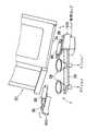
図5に示されているように一対の吸着パッド26の両側には一対の支持ローラ96が配置されている。これら支持ローラ96はカード繰出し方向に沿って延び、且つ、それらの軸線はホッパ20の傾斜に合わせて傾斜されている。
各支持ローラ96はローラホルダ98に回転自在にして軸支されている。より詳しくは、ローラホルダ98は吸着パッド26側に向けて開口したコ字形のプレートからなり、支持ローラ96はローラホルダ98の開口部内にて回転自在に支持されている。各ローラホルダ98は連結板100の上端に連結されており、これら連結板100の下端は対応する側の揺動レバー102の一端に支持されている。これら揺動レバー102はアングル形状をなし、下方に一旦延びた後、互いに近接する方向に折曲され、そして、その他端が支持軸104に回動自在に支持されている。これら支持軸104はブラケット106に取り付けられており、このブラケット106はフレーム38に固定されている(図7参照)。
【0029】
各揺動レバー102の折曲部には連接ロッド108の上端がそれぞれ連結されており、これら連接ロッド108は下方に向けて延び、前述したカム機構46により上下動されるようになっている。
再度、図2を参照すると、ホッパ20の下側にはベルトコンベア110が配置されており、このベルトコンベア110は吸着パッド26の近傍からカード繰出し方向に水平に延びている。ベルトコンベア110は、カード繰出し方向でみて前後に配置されたローラ112,114間に無端状のベルト116を掛け回して構成され、このベルト116は駆動ローラ118の回転により一方向に走行可能となっている。なお、参照符号117はベルト116のテンションローラを示している。
【0030】
前側のローラ112の直上にはベルト116を挟んでフリーローラ120が配置されており、このフリーローラ120は連接ロッド122を介してカム機構46に接続され、このカム機構46の働きにより上下動されるようになっている。図7を参照すれば、連接ロッド122、そして、前述した一対の連接ロッド108を上下動させるカム機構46の部分が具体的に示されている。カム機構46の前述した支持軸62には更に別のカムフォロアレバー124,126が回転自在に取り付けられており、一方のカムフォロアレバー124に連接ロッド122の下端が連結されている。連接ロッド122の上端は、揺動軸128を中心として上下に回動する揺動プレート130に連結されており、この揺動プレート130に前述のフリーローラ120が回転自在に支持されている。
【0031】
他方のカムフォロアレバー124にはローラ状のカムフォロア132が回転自在に取り付けられており、このカムフォロア132は、駆動軸80に固着して取り付けられたカムディスク134のカム面に常時転接されている。即ち、カムフォロアレバー124とフレーム38との間には引張りコイルばねからなる復帰ばね136が架け渡されており、この復帰ばね136はカムフォロアレバー124を回動付勢している。
【0032】
駆動軸80によりカムディスク134が回転されると、連接ロッド122はカムフォロアレバー124を介して上下動される。このような連接ロッド122の上下動は揺動プレート130の上下方向の揺動に変換され、これにより、フリーローラ120はベルトコンベア110のベルト116に対して接離する。
カムフォロアレバー126には、一対の連接ロッド108のうち、一方の連接ロッド108の下端が連結されている。カムフォロアレバー126にもローラ状のカムフォロア138が設けられており、このカムフォロア138は、駆動軸80に固着して取り付けられたカムディスク140のカム面に常時転接されている。このため、カムフォロアレバー126とフレーム38との間にもカムフォロアレバー126を回動付勢するために、引張りコイルはねからなる復帰ばね142が架け渡されている。
【0033】
図3に示されているように、他方の連接ロッド108はその下端がカムフォロアレバー126と連動して回動するカムレバー144に連結されている。なお、図3から前述した連接ロッド、カムフォロアレバー及びカムディスクの各々の配置を明瞭に理解することができる。
駆動軸80によりカムディスク140が回転されると、一対の連接ロッド108はカムフォロアレバー126及びカムレバー144を介し、同期して上下動する。これら連接ロッド108の上下動は、図6を参照すればより明らかなように、一対の揺動レバー102の往復回動に変換され、これにより、一対の支持ローラ96はホッパ20の幅方向に円弧運動して互いに接離し、ホッパ出口直下の作動位置と、ホッパ出口の下方且つ側方の退避位置との間にて移動する。
【0034】
再度、図7を参照すると、ホッパ20の前方には電磁バルブを内蔵したエアノズル146が配置されており、このエアノズル146は圧空源から供給された圧縮空気をホッパ出口の左右の底壁部材24間に向けて噴出可能となっている。
図8を参照すると、前述したベルトコンベア110への動力伝達系が示されている。この動力伝達系はベルトコンベア110の駆動ローラ118と同軸にして取り付けられたギヤ148を備え、このギヤ148はギヤ150に噛み合っている。ギヤ150には同軸にしてスプロケット152が備えられており、このスプロケット152は駆動チェーン154を介して駆動スプロケット156に接続されている。駆動スプロケット156は前述した駆動軸80の他端に取り付けられており、前述した各カムディスクと同様に電動モータ86により回転される。
【0035】
なお、駆動スプロケット156とスプロケット152との間にて、駆動チェーン154はガイドスプロケット158及びテンションスプロケット160により案内されており、これらスプロケット158,160は図3に示されているようにフレーム38に回転自在に支持されている。
駆動軸80により駆動スプロケット156が回転されると、この回転が駆動チェーン154、スプロケット152、ギヤ150,148を介して駆動ローラ118に伝達され、この駆動ローラ118の回転を受け、ベルトコンベア110は一方向に駆動される。
【0036】
更に、ベルトコンベア110上には、ガイドユニット162が前後に離間して配置されている。これらガイドユニット162は一対ずつのガイドローラ164を回転自在に支持しており、これらガイドローラ164はベルトコンベア110のベルト116上に接触している。
更にまた、ガイドユニット162間にはベルト116を上下に挟む受けローラ166及びセンサローラ168が配置されている。センサローラ168はアームを介して揺動自在に支持され、その揺動はセンサ(図示しない)にて検出可能となっている。
【0037】
次に、図9〜図13を追加し、前述したカード繰出し装置2によるカードCの繰出し方法について説明する。また、以下の説明により、前述のカムディスクにより決定される吸着パッド26、支持ローラ96及びフリーローラ120の作動タイミングもまた明瞭となる。
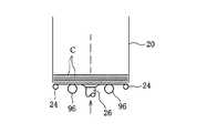
図9に示されているように前述した一対の支持ローラ96は作動位置にあり、ホッパ出口の直下、即ち、ホッパ20内の最下位にあるカードCの両側縁部分を下方から支持している。
【0038】
このような状態にて、一対の吸着パッド26が前述した繰出し動作を開始すると、これら吸着パッド26は後退しながらホッパ出口に向けて上昇し、その上限位置に位置付けられる。この上限位置にて、各吸着パッド26は、一対の支持ローラ96間にて、最下位のカードCの中央部分に接触する。この時点で、一対の吸着パッド26はサクション圧の供給を受け、最下位のカードCを吸着する。ここで、一対の吸着パッド26は最下位のカードCの前端部分、つまり、上方に向けて持ち上がった部分を吸着する(図11中の2点鎖線を参照)。
【0039】
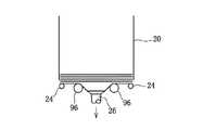
この後、繰出し動作が進み、一対の吸着パッド26が下降し始めても、一対の支持ローラ96は作動位置に維持されている。それ故、一対の吸着パッド26が最下位のカードCを下方に引き出す際、その最下位のカードCはその両側縁部分が図10及び図11に示されているように一対の支持ローラ96にて拘束されているので、その中央部分がU字形に弾性変形される。
【0040】
この際、最下位のカードCと次のカードCとが密着状態にあり、これら両者がともにU字形に弾性変形しようとしても、次のカードCは自身の復元力により最下位のカードCから分離され、これらカードCの間にはそのカード繰出し方向に延びる貫通通路が形成される。より詳しくは、次のカードCの弾性変形は一対の支持ローラ96間における狭い領域に形成されるため、その復元力は最下位のカードCと次のカードCとの間の密着力に比べて十分に十分に大となり、一対の吸着パッド26により吸着されている最下位のカードCのみがその弾性変形を維持でき、この結果、最下位のカードCは次のカードCから確実に分離される。
【0041】
また、ホッパ20は前述したように傾斜されていることから、ホッパ20内における積層カード全体の重量は最下位のカードCの後端部分に大きく加わり、その前端部分に加わる圧力は軽減された状態にある。それ故、最下位のカードCと次のカードCとの前端部分同士の密着力は小さく、一対の吸着パッド26はその吸着引き出しにより、最下位のカードCの前端部分を次のカードCの前端部分から容易に分離することができる。
【0042】
最下位のカードCが弾性成変形される際、前述したエアノズル146(図7参照)から圧縮空気が最下位のカードCと次のカードCとの間に向けて噴出され、これらカード間の貫通通路内を流れる。このような圧縮空気の流れは、最下位のカードCと次のカードCとの分離を促進し、また、吸着パッド26による最下位のカードCの吸着をより確実なものにする。
【0043】
この後、一対の吸着パッド26が更に下降すると、図12に示されるように一対の支持ローラ96はその作動位置から退避位置に向けて円弧運動し、ホッパ出口の底部材24と干渉することなく、その下方且つ側方に逃げ、これら支持ローラ96による最下位のカードCの拘束が解放される。
吸着パッド26がその下限位置まで更に下降し、その吸着したカードCが一対の支持ローラ96間から抜け出すと、図13に示すように吸着カードCは自身の復元力により平坦な状態に復帰し、そして、この過程にて、一対の支持ローラ96はその退避位置に到達した後、作動位置に復帰する。また、この際の吸着パッド26の下降は、図11中の2点鎖線で示されているようにカード繰出し方向への前進を伴い、これにより、吸着カードCはその前端がベルトコンベア11の始端上に載置される。
【0044】
このとき、前述したフリーローラ120は図11中実線で示すようにベルトコンベア110の始端から上昇し、吸着カードCにおける前端の進入を許容する状態にある。この後、フリーローラ120がベルトコンベア110に向けて下降すると、吸着カードCの前端はベルトコンベア110のベルト116とフリーローラ120との間にて挟持され、また、この時点で、一対の吸着パッド26によるカードCの吸着が解除される。従って、そのカードCはベルト116の走行に伴い、ベルトコンベア110上をカード繰出し方向に移送される。
【0045】
ベルトコンベア110上の移送過程にて、カードCが前述したセンサローラ168(図8参照)を通過すると、センサローラ168を揺動させ、その揺動角がセンサにより検出される。従って、センサからの検出信号に基づき、センサローラ168を通過するカードCが1枚であるか否かの確認を行うことができる。
この後、一対ずつの吸着パッド26及び支持ローラ96、そして、フリーローラ120は前述の動作を繰り返し、これにより、ホッパ20からカードCが1枚ずつ繰り返して繰り出され、そして、繰り出されたカードCはベルトコンベア110により前述した集積セクション4(図1参照)に供給される。
【0046】
本発明は上述の実施例に制約されるものではなく、種々の変形が可能である。例えば、吸着パッド26は必ずしも一対必要となるものでなく、1個であってもよい。また、吸着パッド26に繰出し動作を与える機構に関しても任意に変更可能である。
【0047】
【発明の効果】
以上説明したように、本発明のカード繰出し装置及びその繰出し方法(請求項1,4)によれば、ホッパ出口から最下位のカードを吸着して繰り出す際、そのカードを一対の支持ローラにて拘束し、カードにU字形の弾性変形を積極的に与えるようにしたので、最下位のカードと次のカードとの間の分離が良好且つ安定して行え、カードを1枚ずつ確実に繰り出すことができる。
【0048】
また、一対の支持ローラはその作動位置と退避位置との間にて円弧経路に沿って往復移動するので(請求項2)、これら支持ローラがホッパ出口と干渉することもなく、また、吸着されたカードの繰出しに大きな抵抗になることもない。
更に、最下位のカードがU字形に弾性変形される際、そのカードの上面に圧縮空気が吹き付けられると(請求項3)、この圧縮空気は最下位のカードと次のカードとの間の分離をより促進する。
【図面の簡単な説明】
【図1】カード集積包装機内にて集積包装されるカードの流れを示した概略図である。
【図2】カード繰出し装置の概略的な構成を一部破断して示す側面図である。
【図3】ホッパを省略したカード繰出し装置を一部破断して示す背面図である。
【図4】吸着パッドに繰出し動作を与える駆動系の構成を示した図である。
【図5】ホッパ出口に対し、吸着パッド及び支持ローラの配置を示した斜視図である。
【図6】一対の支持ローラを往復運動可能に支持する機構を示した図である。
【図7】支持ローラ及びフリーローラの駆動系を示した図である。
【図8】ベルトコンベア及びその駆動系を示した図である。
【図9】ホッパ内の最下位のカードが吸着パッドに吸着された状態を示す図である。
【図10】図9の状態から吸着パッドが最下位のカードを繰出し始め、カードがU字形に弾性変形した状態を示す図である。
【図11】図10に対応した状態での弾性変形したカードを示す側面図である。
【図12】吸着パッドが更に下降した状態を示す図である。
【図13】吸着パッドによりカードが完全に繰り出された状態を示す図である。
【符号の説明】
20 ホッパ
24 底部材
26 吸着パッド
30 パッド駆動ロッド(パッド駆動手段)
32 揺動サポート(パッド駆動手段)
44 連接ロッド(パッド駆動手段)
46 カム機構(パッド駆動手段及びロッド駆動手段)
60 連接ロッド(パッド駆動手段)
96 支持ローラ
102 揺動レバー(ローラ駆動手段)
108 連接ロッド(ローラ駆動手段)
146 エアノズル[0001]
BACKGROUND OF THE INVENTION
The present invention relates to a card feeding device and a feeding method for feeding a flexible card stacked and accommodated in a hopper one by one from its lowest card.
[0002]
[Related background]
This type of card feeding device employs either an upper surface feeding system that feeds one by one from the uppermost card in the hopper, or a lower surface feeding system that feeds one by one from the lowermost card. ing. The upper surface feeding method is suitable for feeding a large-sized card whose weight per sheet is relatively heavy. On the other hand, for feeding a small-sized card such as a prepaid card, the replenishment into the hopper is easy. Generally, the lower surface feeding method is adopted.
[0003]
In the bottom payout method, the weight of the entire card stored in the lowest card in the hopper is added, and the prepaid card is smooth on both sides, so the lowest card and the next card are Easy to adhere strongly. For this reason, when the lowest card is paid out from the hopper, the next card may also be drawn out together with the lowest card.
[0004]
In order to prevent such two cards from being fed out, for example, a card feeding device disclosed in Japanese Patent Laid-Open No. 3-12034 is known. This known card feeding device is provided with a single roller in addition to a suction pad below the hopper, the lowest card in the hopper is supported by the roller at the center, and the suction pad is One end of the card is sucked and lowered. Here, since the lower part of the center of the card is prevented by the roller, the lowering of the suction pad elastically deforms one end of the card in an arc shape, and this elastic deformation is used to make Separation of one card from the next is achieved.
[0005]
[Problems to be solved by the invention]
However, a card made of plastic such as a prepaid card is excellent in flexibility, and particularly easily elastically deformed in the longitudinal direction. For this reason, when the next card is elastically deformed in the same manner as the lowest card, the restoring force generated by the elastic deformation is weak, and the adhesion force between the lowest card and the next card against this restoring force is weak. May overcome. In this case, the next card is also elastically deformed in the same manner as the lowest card, and these two cards are fed out simultaneously, so that one card can be reliably delivered. Can not.
[0006]
The present invention has been made based on the above-described circumstances, and an object of the present invention is to provide a card feeding device and a feeding method thereof that can reliably feed cards one by one from a hopper.
[0007]
[Means for Solving the Problems]
An apparatus for carrying out the card feeding method of the present invention includes a hopper having a downward hopper outlet, and a suction pad arranged below the hopper outlet. A card feeding operation combining a vertical contact / separation motion with respect to the exit and a horizontal advance / retreat motion is provided.
[0008]
The card feeding device (Claim 1) further includes a pair of support rollers disposed on both sides of the suction pad below the hopper outlet, and these support rollers extend in the advancing and retreating direction of the suction pad. Each support roller is reciprocated by roller driving means between an operating position located immediately below the hopper outlet and a retracted position below the operating position.
[0009]
When the lowest card in the hopper is sucked to the suction pad by the card feeding operation by the suction pad, the pair of support rollers are in the operating position, and support both sides of the lowest card on both sides of the suction pad. is doing. In such a state, the suction pad feeding operation proceeds, accompanied by the lowest card that has been sucked, and when the suction pad descends, the lowermost card is supported on both sides of the suction pad by a pair of support rollers. Therefore, the lowering of both side portions is in a restrained state. For this reason, the lowermost card is pulled out by the suction pad only at the central portion between the support rollers and is elastically deformed into a U shape (Claim 4). Thereafter, the pair of support rollers move from the operating position to the retracted position. Then, the restraint of the lowest card is released, whereby the feeding of the lowest card is completed.
[0010]
When the card is paid out, if the adhesion between the next card in the hopper and the lowermost card is strong, the next card tends to elastically deform into a U shape like the lowermost card. However, since the elastic deformation of these cards is limited only to a narrow region between the support rollers, the restoring force generated by these elastic deformations is large enough to overcome the adhesion force. As a result, only the lowest card sucked by the suction pad can maintain its elastic deformation, and this elastic deformation creates a through passage between the lowest card and the next card in the hopper, and the lowest card. Separate the lower card from the next card.
[0011]
Preferably, the pair of support rollers reciprocate between the operating position and the retracted position along an arc path (claim 2). Such reciprocating movement of the arc of the support roller avoids interference between the support roller and the hopper outlet, and quickly releases the restraint of the card that is fed out.
Further, the card feeding device is provided with a pair of support robots during card feeding.Troller An air nozzle that blows out compressed air along the receding direction of the suction pad is further included. In this case, when the lowermost card is elastically deformed into a U shape to form the through passage, the air nozzle ejects compressed air into the through passage. The jetted compressed air flows through the through passage and promotes separation between the lowest card and the next card.
[0012]
DETAILED DESCRIPTION OF THE INVENTION
FIG. 1 schematically shows a series of flow from the accumulation of cards in the card accumulation packaging machine to the accumulation packaging. First, the card stacking and packaging machine is provided with a card feeding device 2, and the card feeding device 2 feeds cards C one by one from one selected hopper. The fed-out card C is transferred to the accumulation section 4, where the cards C are accumulated on the accumulation cards S of a predetermined number, and the accumulation card S is transferred from the accumulation section 4 to the beginning of the packaging line 6. It is transferred to a supply position defined in the vicinity.
[0013]
The packaging line 6 includes a turret 8 at the starting end, and a drooping line of the packaging film F is secured between the turret 8 and the supply position. The packaging film F is obtained by cutting the film web FW fed from the film roll FR to the drooping line into a predetermined length. During the feeding of the film web FW, the tear tape T is applied to the film web FW, and the tear tape T is fed from the tape roll TR.
[0014]
The integrated card S is inserted into the pocket of the turret 8 together with the packaging film F. At this time, the packaging film F is folded around the integrated card S. After that, as the turret 8 is rotated, the integrated card S is wrapped in the packaging film F in a cylindrical shape through the cylinder flap fold and the cylinder seal of the packaging film F, and discharged from the pocket of the turret 8 to the ear fold section of the packaging line. Is done. In the process of being transported in the ear fold section, side sealing is performed after the left and right ear folds of the packaging film F, the packaging of the integrated card S by the packaging film F is completed, and the packaged product H is obtained.
[0015]
Thereafter, a label L is attached to the packaged product H, and the packaged product H is discharged to a discharge section 10 that transports the packaged product H in a stacked state. The label L is obtained by cutting the label web LW fed out from the label roll LR into a predetermined length, and a
[0016]
Next, the card feeding device 2 described above will be described in detail.
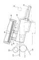
Referring to FIG. 2, the card feeding device 2 has a
[0017]
The
[0018]
In each
[0019]
A pair of
The
[0020]
A
[0021]
On the other hand, as shown in FIG. 2, a
[0022]
Referring to FIG. 4, a part of the
[0023]
Cam follower levers 64 and 66 are rotatably attached to the
[0024]
As apparent from FIG. 3, the
[0025]
A
[0026]
When the
[0027]
The reciprocating rotation of the
[0028]
As shown in FIG. 5, a pair of
Each
[0029]
The upper ends of the connecting
Referring again to FIG. 2, a
[0030]
A
[0031]
A roller-
[0032]
When the
The
[0033]
As shown in FIG. 3, the lower end of the other connecting
When the
[0034]
Referring again to FIG. 7, an
Referring to FIG. 8, the power transmission system to the
[0035]
The
When the
[0036]
Further, a
Furthermore, a receiving roller 166 and a
[0037]
Next, FIG. 9 to FIG. 13 are added, and the card C feeding method by the card feeding device 2 described above will be described. In addition, the operation timing of the
As shown in FIG. 9, the pair of
[0038]
In this state, when the pair of
[0039]
Thereafter, even when the feeding operation proceeds and the pair of
[0040]
At this time, the lowest card C and the next card C are in close contact with each other, and even if both of them try to elastically deform into a U shape, the next card C is separated from the lowest card C by its own restoring force. A through passage extending in the card feeding direction is formed between the cards C. More specifically, since the elastic deformation of the next card C is formed in a narrow region between the pair of
[0041]
Further, since the
[0042]
When the lowermost card C is elastically deformed, compressed air is ejected from the above-described air nozzle 146 (see FIG. 7) between the lowermost card C and the next card C and penetrates between these cards. It flows in the passage. Such a flow of compressed air promotes the separation of the lowest card C and the next card C, and makes the suction of the lowest card C by the
[0043]
Thereafter, when the pair of
When the
[0044]
At this time, the above-described
[0045]
When the card C passes the above-described sensor roller 168 (see FIG. 8) in the transfer process on the
Thereafter, the
[0046]
The present invention is not limited to the above-described embodiments, and various modifications can be made. For example, a pair of
[0047]
【The invention's effect】
As described above, according to the card feeding device and the feeding method (Claims 1 and 4) of the present invention, when the lowest card is sucked and fed out from the hopper outlet, the card is paired with a pair of support rollers.Troller Since the U-shaped elastic deformation is positively applied to the card, the separation between the lowest card and the next card can be performed well and stably, and the cards are surely one by one. You can pay out.
[0048]
Also, a pair of support robotsTroller Reciprocates along the arc path between the operating position and the retracted position (Claim 2).Troller Does not interfere with the hopper exit, and does not become a great resistance to the feeding of the sucked card.
Furthermore, when the lowest card is elastically deformed into a U shape, when compressed air is blown onto the upper surface of the card (Claim 3), the compressed air is separated between the lowest card and the next card. To promote more.
[Brief description of the drawings]
FIG. 1 is a schematic diagram showing the flow of cards stacked and packaged in a card stacking and packaging machine.
FIG. 2 is a side view showing the schematic configuration of the card feeding device with a part broken away.
FIG. 3 is a rear view showing the card feeding device in which a hopper is omitted, with a part broken away.
FIG. 4 is a diagram showing a configuration of a drive system that applies a feeding operation to a suction pad.
FIG. 5 is a perspective view showing an arrangement of suction pads and support rollers with respect to a hopper outlet.
FIG. 6 is a view showing a mechanism for supporting a pair of support rollers so as to be able to reciprocate.
FIG. 7 is a diagram showing a driving system for a support roller and a free roller.
FIG. 8 is a diagram showing a belt conveyor and its drive system.
FIG. 9 is a diagram showing a state in which the lowest card in the hopper is sucked by a suction pad.
10 is a view showing a state in which the suction pad starts paying out the lowest card from the state of FIG. 9 and the card is elastically deformed into a U shape.
11 is a side view showing an elastically deformed card in a state corresponding to FIG.
FIG. 12 is a view showing a state where the suction pad is further lowered.
FIG. 13 is a view showing a state where the card is completely drawn out by the suction pad.
[Explanation of symbols]
20 Hoppers
24 Bottom member
26 Suction pad
30 Pad drive rod (pad drive means)
32 Swing support (pad drive means)
44 Connecting rod (pad drive means)
46 Cam mechanism (pad driving means and rod driving means)
60 Connecting rod (pad drive means)
96 Support roller
102 Swing lever (roller drive means)
108 Connecting rod (roller drive means)
146 Air nozzle
Claims (4)
Translated fromJapanese前記ホッパ出口の下方に配置された吸着パッドと、
前記吸着パッドに前記ホッパ出口に対する上下方向の接離運動と水平方向の進退運動とを組み合わせたカードの繰出し動作を与え、前記吸着パッドにより前記ホッパ内の最下位のカードを吸着して繰り出すパッド駆動手段と、
前記吸着パッドの両側に配置され、前記吸着パッドの進退方向に沿って延びる一対の支持ローラと、
前記各支持ローラを前記ホッパ出口の直下に位置した作動位置と、この作動位置よりも下方の退避位置との間にて往復移動させるローラ駆動手段とを備え、
前記吸着パッドが前記最下位のカードを吸着して繰り出す際、前記各支持ローラは前記作動位置にあって、前記吸着パッドの両側にて前記最下位のカードを支持することにより前記吸着カードにU字形に弾性変形を与え、この後、退避位置に向けて移動することを特徴とするカードの繰出し装置。A hopper having a hopper outlet that opens downward, and receiving and stacking a flexible card from the hopper outlet on both side edges;
A suction pad disposed below the hopper outlet;
Pad drive that gives the suction pad a card feeding operation that combines a vertical contact / separation movement with respect to the hopper outlet and a horizontal advance / retreat movement, and sucks and feeds the lowest card in the hopper by the suction pad. Means,
A pair of support rollers disposed on both sides of the suction pad and extending along the advancing and retreating direction of the suction pad;
Roller driving means for reciprocally moving each supporting roller between an operating position located directly below the hopper outlet and a retracted position below the operating position;
When the suction pad sucks and feeds out the lowermost card, the support rollers are in the operating position, and the lowermost card is supported on both sides of the suction pad by supporting the lowermost card. A card feeding device characterized by elastically deforming a letter shape and then moving toward a retracted position.
前記カードが繰り出される際、前記吸着パッドを挟む前記カードの両側部分を一時的に拘束し、前記カードにU字形の弾性変形を与えることを特徴とするカードの繰出し方法。In a card feeding method in which flexible cards accommodated in a vertically stacked hopper having a downward hopper outlet are sucked from the hopper outlet one by one with a suction pad and fed out.
A card feeding method, wherein when the card is drawn out, both side portions of the card sandwiching the suction pad are temporarily restrained to give a U-shaped elastic deformation to the card.
Priority Applications (1)
| Application Number | Priority Date | Filing Date | Title |
|---|---|---|---|
| JP32074398AJP3805542B2 (en) | 1998-11-11 | 1998-11-11 | Card feeding device and feeding method |
Applications Claiming Priority (1)
| Application Number | Priority Date | Filing Date | Title |
|---|---|---|---|
| JP32074398AJP3805542B2 (en) | 1998-11-11 | 1998-11-11 | Card feeding device and feeding method |
Publications (2)
| Publication Number | Publication Date |
|---|---|
| JP2000143011A JP2000143011A (en) | 2000-05-23 |
| JP3805542B2true JP3805542B2 (en) | 2006-08-02 |
Family
ID=18124805
Family Applications (1)
| Application Number | Title | Priority Date | Filing Date |
|---|---|---|---|
| JP32074398AExpired - Fee RelatedJP3805542B2 (en) | 1998-11-11 | 1998-11-11 | Card feeding device and feeding method |
Country Status (1)
| Country | Link |
|---|---|
| JP (1) | JP3805542B2 (en) |
Families Citing this family (2)
| Publication number | Priority date | Publication date | Assignee | Title |
|---|---|---|---|---|
| JP2009023800A (en)* | 2007-07-20 | 2009-02-05 | Canon Machinery Inc | Card take-out device |
| TWI856138B (en)* | 2019-07-23 | 2024-09-21 | 日商湯山製作所股份有限公司 | Card loading device, card handling device, card holder and tray transport device |
Family Cites Families (9)
| Publication number | Priority date | Publication date | Assignee | Title |
|---|---|---|---|---|
| JPS60142246U (en)* | 1984-03-02 | 1985-09-20 | 株式会社日本コンラックス | Support mechanism in automatic card ejection device |
| JPH03102034A (en)* | 1989-09-14 | 1991-04-26 | Tokyo Denshi Kogyo Kk | Card feeder |
| JP2904524B2 (en)* | 1990-01-17 | 1999-06-14 | ポーラ化成工業株式会社 | Film feeder |
| JPH06219577A (en)* | 1993-01-26 | 1994-08-09 | Toshiba Corp | Laminate separation device |
| JPH0797082A (en)* | 1993-09-30 | 1995-04-11 | Toshiba Corp | Thin-leaf board take-out device |
| JP2887193B2 (en)* | 1994-03-29 | 1999-04-26 | リズム時計工業株式会社 | Work supply device |
| JPH08290843A (en)* | 1995-04-21 | 1996-11-05 | Nec Eng Ltd | Takeout device for laminated thin plates |
| JPH092681A (en)* | 1995-06-22 | 1997-01-07 | Toshiba Corp | Method and apparatus for obtaining one plate |
| JPH09194056A (en)* | 1996-01-12 | 1997-07-29 | Mitsubishi Materials Corp | Sheet material separating method |
- 1998
- 1998-11-11JPJP32074398Apatent/JP3805542B2/ennot_activeExpired - Fee Related
Also Published As
| Publication number | Publication date |
|---|---|
| JP2000143011A (en) | 2000-05-23 |
Similar Documents
| Publication | Publication Date | Title |
|---|---|---|
| US4433599A (en) | Apparatus for forming and stacking sections severed from a web of tubular film | |
| US3934868A (en) | Top loading, continuous suction feeder attachment for printing apparatus | |
| CN1880101B (en) | Paper stack delivery device | |
| JP3320032B2 (en) | Modular automatic envelope insertion machine | |
| CN102107565B (en) | Bookmaking apparatus | |
| JP3805542B2 (en) | Card feeding device and feeding method | |
| JP2005112633A (en) | Method for manufacturing bound book and magazine or catalog | |
| JP3236948B2 (en) | Method and apparatus for taking out and opening a folded carton | |
| EP2088082B1 (en) | Strip-pack apparatus, and gripping device and unwrinkling device for use in the apparatus | |
| WO2016135628A1 (en) | Wrapping group and wrapping method for wrapping products, in particular editorial products, in containment bands | |
| JP4641256B2 (en) | Sheet take-out device and packing device | |
| JP4466353B2 (en) | Printer | |
| JP4345657B2 (en) | Printer | |
| JP4457878B2 (en) | Inkjet printer | |
| JP4678646B2 (en) | Inkjet printer | |
| JP4591067B2 (en) | Printer | |
| JP4341543B2 (en) | Printer | |
| JP3522539B2 (en) | Design paper attachment device to bag mouth | |
| JP4333566B2 (en) | Printer | |
| JP3716103B2 (en) | Paper sheet separator | |
| JP2000109228A (en) | Device for supplying sheet-shaped material | |
| JP2006175733A (en) | Inkjet printer | |
| JP2001002031A (en) | Working device for packaging material | |
| JP2001002316A (en) | Folding back device for lowermost paper piece of foldedly accumulated articles | |
| JP2006181934A (en) | Printer |
Legal Events
| Date | Code | Title | Description |
|---|---|---|---|
| A621 | Written request for application examination | Free format text:JAPANESE INTERMEDIATE CODE: A621 Effective date:20040220 | |
| A977 | Report on retrieval | Free format text:JAPANESE INTERMEDIATE CODE: A971007 Effective date:20051205 | |
| A131 | Notification of reasons for refusal | Free format text:JAPANESE INTERMEDIATE CODE: A131 Effective date:20060111 | |
| A521 | Written amendment | Free format text:JAPANESE INTERMEDIATE CODE: A523 Effective date:20060301 | |
| TRDD | Decision of grant or rejection written | ||
| A01 | Written decision to grant a patent or to grant a registration (utility model) | Free format text:JAPANESE INTERMEDIATE CODE: A01 Effective date:20060419 | |
| A61 | First payment of annual fees (during grant procedure) | Free format text:JAPANESE INTERMEDIATE CODE: A61 Effective date:20060510 | |
| R150 | Certificate of patent or registration of utility model | Free format text:JAPANESE INTERMEDIATE CODE: R150 | |
| FPAY | Renewal fee payment (event date is renewal date of database) | Free format text:PAYMENT UNTIL: 20090519 Year of fee payment:3 | |
| FPAY | Renewal fee payment (event date is renewal date of database) | Free format text:PAYMENT UNTIL: 20090519 Year of fee payment:3 | |
| FPAY | Renewal fee payment (event date is renewal date of database) | Free format text:PAYMENT UNTIL: 20100519 Year of fee payment:4 | |
| FPAY | Renewal fee payment (event date is renewal date of database) | Free format text:PAYMENT UNTIL: 20100519 Year of fee payment:4 | |
| FPAY | Renewal fee payment (event date is renewal date of database) | Free format text:PAYMENT UNTIL: 20110519 Year of fee payment:5 | |
| FPAY | Renewal fee payment (event date is renewal date of database) | Free format text:PAYMENT UNTIL: 20120519 Year of fee payment:6 | |
| FPAY | Renewal fee payment (event date is renewal date of database) | Free format text:PAYMENT UNTIL: 20120519 Year of fee payment:6 | |
| FPAY | Renewal fee payment (event date is renewal date of database) | Free format text:PAYMENT UNTIL: 20130519 Year of fee payment:7 | |
| FPAY | Renewal fee payment (event date is renewal date of database) | Free format text:PAYMENT UNTIL: 20130519 Year of fee payment:7 | |
| FPAY | Renewal fee payment (event date is renewal date of database) | Free format text:PAYMENT UNTIL: 20130519 Year of fee payment:7 | |
| FPAY | Renewal fee payment (event date is renewal date of database) | Free format text:PAYMENT UNTIL: 20140519 Year of fee payment:8 | |
| R250 | Receipt of annual fees | Free format text:JAPANESE INTERMEDIATE CODE: R250 | |
| R250 | Receipt of annual fees | Free format text:JAPANESE INTERMEDIATE CODE: R250 | |
| R250 | Receipt of annual fees | Free format text:JAPANESE INTERMEDIATE CODE: R250 | |
| R250 | Receipt of annual fees | Free format text:JAPANESE INTERMEDIATE CODE: R250 | |
| LAPS | Cancellation because of no payment of annual fees |