JP3805413B2 - Vehicle travel guidance device - Google Patents
Vehicle travel guidance deviceDownload PDFInfo
- Publication number
- JP3805413B2 JP3805413B2JP25909795AJP25909795AJP3805413B2JP 3805413 B2JP3805413 B2JP 3805413B2JP 25909795 AJP25909795 AJP 25909795AJP 25909795 AJP25909795 AJP 25909795AJP 3805413 B2JP3805413 B2JP 3805413B2
- Authority
- JP
- Japan
- Prior art keywords
- route
- destination
- link
- current location
- road
- Prior art date
- Legal status (The legal status is an assumption and is not a legal conclusion. Google has not performed a legal analysis and makes no representation as to the accuracy of the status listed.)
- Expired - Lifetime
Links
- 238000013500data storageMethods0.000claims1
- 238000001514detection methodMethods0.000claims1
- 238000000034methodMethods0.000description8
- 238000010586diagramMethods0.000description5
- 239000000470constituentSubstances0.000description1
- 239000004973liquid crystal related substanceSubstances0.000description1
Images


Landscapes
- Navigation (AREA)
- Traffic Control Systems (AREA)
- Instructional Devices (AREA)
Description
Translated fromJapanese【0001】
【発明の属する技術分野】
本発明は、設定された目的地経路により走行案内を行う車両用走行案内装置に関する。
【0002】
【従来の技術】
従来、この種の車両用走行案内装置において、目的地経路を設定するための経路対象道路を交差点(ノード)間を接続するリンクとして規定し、このリンクを用いて出発地から目的地に至る目的地経路が設定されると、目的地経路を道路地図上に強調表示(太線表示)したり、あるいはその目的地経路に従って車両の進行すべき方向を音声指示したりして、目的地に対する走行案内を行うようにしている。
【0003】
この従来のものにおいては、出発地を設定する場合、現在地に最も近い交差点を出発地としたり(特開昭61ー216099号公報)、現在地に最も近いリンク上の位置を出発地としている。また、現在地を新たなノードとして設定するとともに、その設定されたノードを出発地とするものもある(特開平5ー67151号公報)。
【0004】
【発明が解決しようとする課題】
上記従来のものによれば、図7に示すように、車両が経路対象道路から外れ、その外れた現在地Dから目的地への経路を設定する場合、現在地Dに最も近い交差点Iもしくは最も近いリンク上の位置Hを出発地とし、その出発地から目的地経路を設定する。
【0005】
しかしながら、現在地Dと地点I、H間に河川等の障害物があった場合、現在地Dから地点I、Hには容易には辿り着くことができず、適切なる目的地経路の設定ができないという問題がある。上記特開平5ー67151号公報に示すように現在地を新たなノードとして設定した場合も、その現在地から地点I等を経て目的地経路が設定される場合があり、上記したのと同様の問題が生じる。
【0006】
このような場合、河川等の障害物の情報を記憶しておき、その障害物を横切るような目的地経路の設定を行わないようにすることが考えられるが、その障害物に関する情報調査に多大な作業を必要とするとともに、障害物の形状が複雑な場合が多いためそれに関するデータ量が膨大になり、そのような障害物に関する情報を記憶させるのは実際的ではない。
【0007】
本発明は上記問題に鑑みてなされたもので、現在地が経路対象道路から外れた場合であっても確実に目的地に到達することができる目的地経路の設定を行うことを目的とする。
【0008】
【発明の概要】
上記目的を達成するため、請求項1に記載の発明においては、出発地から目的地への目的地経路の設定において、現在地が経路対象道路上にない時には、複数のリンクデータの内、車両が最後に存在した経路対象道路に対するリンク上で、現在地に最も近い交差点若しくはそのリンクへの最近接地点に出発地を設定することを特徴としている。このことにより、現在地が経路対象道路から外れた場合であっても、車両が最後に存在した経路対象道路に対するリンクであればそこに戻ることができるため、目的地に確実に到達できる目的地経路の設定を行うことができる。
【0009】
請求項2に記載の発明においては、車両が最後に存在した経路対象道路を示すリンクデータを不揮発記憶することを特徴としている。このことにより、現在地が経路対象道路から外れ、そこで車両運転を中断し、その後運転を再開する場合であっても、データの不揮発記憶により、その場所において、上記した目的地経路の設定を行うことができる。
【0011】
【発明の実施の形態】
以下、本発明を図に示す実施形態について説明する。
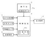
図1に、本発明の一実施形態を示す車両用走行案内装置の全体構成を示す。
本実施形態においては、車両の現在地を検出するため、GPS受信機1、方位センサ2、車輪速センサ3を備えている。GPS受信機1は、人工衛星からの電波を受信して、車両の現在地を示す信号を出力する。方位センサ2は、例えば地磁気を利用して車両の進行方向を検出し方位信号を出力する。車輪速センサ3は、車輪の回転数により車両の走行距離を検出し距離信号を出力する。
【0012】
記憶装置4は、地図データを記憶するCDROMの記憶媒体を備え、制御装置6に地図データを出力する。
操作部5は、車両の乗員等により操作される種々のキーを有し、走行案内に必要な操作信号を出力する。なお、目的地経路を設定する場合には、目的地キー5aが操作され、例えば表示装置7の画面上の位置を指定操作することにより、目的地が設定される。
【0013】
制御装置6は、マイクロコンピュータ等のコンピュータ手段を含んで構成されたものであって、上記各構成要素1〜5からの信号により、表示装置7に車両の走行領域の道路地図を表示させるとともに、その道路地図上に車両の現在地を表示させる演算処理を実行する。さらに、目的地に対する経路案内を行う時には、目的地に対する目的地経路を設定して、目的地経路を表示装置7に強調表示させる演算処理を実行する。また、その目的地経路における出発地を設定するために、現在地が最後に存在した経路対象道路を示すデータ(後述する経路用リンクID)および現在地座標を、車両の非運転時においても不揮発記憶する不揮発性メモリ6aを備えている。
【0014】
表示装置7は、車両のインストルメントパネル部に設けられ、現在地および道路地図を表示する。この表示装置7としては、液晶表示装置、CRT表示装置等を用いることができる。
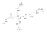
図2に、上記地図データの構成を示す。
地図データは、表示用道路データ、経路用道路データ(経路対象道路のデータ)から構成されている。
【0015】
表示用道路データは、道路地図表示を行うための形状点情報と、表示用リンクID情報と、属性情報とから構成されている。
形状点情報は、2次元座標点により特定される複数のリンクの集合により道路の形状を規定するものであって、道路(ストローク)単位で、ストロークを構成する各リンク毎に、リンクを構成する座標データを記憶する。例えば、図3に示すような道路において、ストロークS1はリンクL1〜L3により、ストロークS2はリンクL4、L5により構成されている時、リンクL1は座標p11〜P13により、リンクL2は座標p13〜16により、リンクL3は座標p16、P17により構成され、リンクL4は座標p21、p22、P13により、リンクL5は座標p13、p24、p25により構成される。
【0016】
ここで、複数のリンクに対してそれぞれリンクIDが付されており、リンクL1〜L5がそのリンクIDを構成している。このリンクIDは、全国の道路における各リンクに対してユニークなID番号として付されたものであり、ストローク内で連続番号として付されたものである。
表示用リンクID情報は、表示用道路の各ストロークにおけるリンク列の始端と終端のリンクIDから構成されている。属性情報は、道路の種別(高速道路、国道等)、道路車線数、一方通行等の規制に関する情報などから構成されている。
【0017】
制御装置6は、道路表示時に、各ストロークにおける始端と終端のリンクIDから、その間の連続したリンクID列を特定し、このリンクID列から、形状点情報をアクセスして、各ストロークにおけるリンクを構成する座標点を抽出する。この抽出した座標点を属性情報に応じて連結表示させ、道路地図を表示装置7に表示させる。
【0018】
一方、目的地経路の設定に用いられる経路用道路データは、経路用リンクID情報とネットワーク情報とから構成されている。
経路用リンクID情報は、リンクIDとリンクコストとネットワーク情報へのポインタから構成されている。ネットワーク情報は、道路リンクが他のリンクとどのように接続しているかの情報、例えばリンクAはリンクB、C、Dと接続しているといった情報である。
【0019】
制御装置6は、経路案内時に、リンクコストおよびネットワーク情報を用いて現在地から目的地への最適経路を計算し、その経路をリンクID列として特定し、このリンクID列から、形状点情報をアクセスする。そして、形状点情報によって特定される座標点を連結して目的地経路を表示装置7に強調表示させる。
上記したように、リンクIDにより表示用道路データと経路用道路データとが関連付けられており、目的地経路設定時にリンクIDから形状点情報をアクセスして目的地経路の強調表示を行わせることができる。
【0020】
次に、制御装置6におけるメインの演算処理について図4に示すフローチャートを基に説明する。
制御装置6は、GPS受信機1、方位センサ2、車輪速センサ3からの信号により現在地座標を求め(ステップ101)、記憶装置4から表示用道路データを読み込み、現在地を含む道路地図を現在地とともに表示装置7に表示させる(ステップ102)。この道路地図の表示については、上述した通りである。また、車両の現在地が、表示された道路上に位置するようにマップマッチング処理が行われる。なお、目的地経路が設定された場合には、表示装置7に目的地経路を強調表示させる(ステップ103)。
【0021】
次に、制御装置6における目的地経路の設定について図5に示すフローチャートに従って説明する。
制御装置6は、まず上記のようにして求めた現在地が経路対象道路上にあるか否かを判定する(ステップ201)。車両が表示されている道路上を走行している時には、上述したマップマッチング処理により車両の現在地はいずれかのリンク上にある。このリンクに対するリンクIDが経路用リンクIDに含まれていれば現在地が経路対象道路上にあると判断される。
【0022】
現在地が経路対象道路上にある時は、その経路用リンクIDおよび現在地座標を不揮発性メモリ6aに更新記憶する(ステップ202)。
一方、車両が表示されている道路からはずれた場合、あるいは表示されている道路上であってもその道路に対するリンクが経路用リンクでない時には、現在地が経路対象道路上にないとして、不揮発性メモリ6aへの更新記憶を行わない。
【0023】
従って、上記した処理により、不揮発性メモリ6aには、最新の経路用リンクIDおよび現在地座標が記憶される。言い換えれば、車両が最後に存在した経路対象道路に対する経路用リンクIDおよび現在地座標が記憶される。
その後、目的地経路を設定するために目的地キー5aが操作されると、ステップ203の判定がYESになり、目的地の設定を行う(ステップ204)。この場合、操作部5の操作により目的地が設定される。この目的地の設定については従来のものと同様である。
【0024】
次に、現在地が経路対象道路上にあるか否かを判定する(ステップ205)。この判定は、ステップ201と同様にして行う。現在地が経路対象道路上にある時には、その現在地を出発地として目的地への経路を計算する(ステップ206)。
この経路計算は、例えば、出発地のノードから目的地のノードに至るまでの経路をダイクストラ法を用いたコスト計算により設定する。なお、出発地、目的地がノード上にない時には、出発地、目的地を仮想ノードとして設定する。このダイクストラ法において出発地のノードが存在する開始リンクから目的地のノードが存在する終了リンクまでの各リンクでの経路コストを例えば数1を用いて計算する。
【0025】
【数1】
経路コスト=リンク長×道路幅係数×道路種別係数
ここで、リンク長はノード間の距離であり、道路幅係数とは道路幅の大きさに対して設定される係数であり、道路種別係数とは、有料道路等の道路種別に応じて設定される係数である。これらリンク長、道路幅係数、道路種別係数は、経路用リンクID情報におけるリンクコストとして記憶されている。
【0026】
そして、出発地のノードから目的地のノードまでの経路コストの総和のうち最もコストの小さいものが、最適経路として設定される。そして、そのコスト最小値の経路を目的地から出発地に向かって順に辿り、それを逆にして出発地から目的地への経路を、図6に示すように、リンクID列として特定する。
一方、現在地が経路対象道路上にない時には、不揮発性メモリ6aに記憶された経路用リンクIDおよび現在地座標により、経路用リンクIDを開始リンクとし、その記憶された現在地を出発地として上記と同様、ダイクストラ法を用いたコスト計算により目的地への経路を計算する(ステップ207)。
【0027】
上記のようにして目的地へのリンクID列が設定されると、制御装置6は、図4のステップ103において、リンクID列から形状点情報をアクセスし、それらを連結して目的地経路を表示装置7に強調表示させる。
従って、現在地が、図7に示すように、経路対象道路から外れているような場合には、経路対象道路に最後に存在した地点Bを出発地として目的地経路B→E→F→G→……が設定されるので、河川等の障害物があったとしても元の道路から確実に目的地に到達することができる。このように車両が経路対象道路から外れその近辺に障害物等が存在する場合としては、河川敷きに車両が進んでその先に河川がある場合あるいは広い駐車場に入って出口が限られている場合などがある。
【0028】
なお、上記実施形態においては、最後に走行した経路対象道路上の現在地を出発地として設定するものを示したが、その経路対象道路上であれば、現在地に最も近い交差点もしくはその走行リンクへの最近接地点としてもよい。
また、走行案内としては、目的地経路を表示するものに限らず、目的地経路に従って音声案内を行うものでもよく、その両方を用いるようにしてもよい。
【図面の簡単な説明】
【図1】本発明の一実施形態を示す全体構成図である。
【図2】地図データの構成を示す構成図である。
【図3】図2に示す形状点情報の構成を説明するための説明図である。
【図4】図1に示す制御装置のメインの演算処理を示すフローチャートである。
【図5】図1に示す制御装置の目的地経路設定処理を示すフローチャートである。
【図6】出発地から目的地に至るリンクID列を示す図である。
【図7】現在地が経路対象道路から外れた場合の経路設定を説明するための図である。
【符号の説明】
1…GPS受信機、2…方位センサ、3…車輪速センサ、4…記憶装置、
5…操作部、6…制御装置、6a…不揮発性メモリ、7…表示装置。[0001]
BACKGROUND OF THE INVENTION
The present invention relates to a vehicular travel guidance device that provides travel guidance according to a set destination route.
[0002]
[Prior art]
Conventionally, in this type of vehicle travel guidance device, a route target road for setting a destination route is defined as a link connecting intersections (nodes), and the purpose of using this link to reach the destination from the departure point When a destination route is set, the destination route is highlighted (bold line) on the road map, or the direction in which the vehicle should travel is voiced according to the destination route, and driving guidance for the destination is given. Like to do.
[0003]
In this prior art, when setting the departure point, the intersection closest to the present location is set as the departure point (Japanese Patent Laid-Open No. 61-216099), or the position on the link closest to the present location is set as the departure point. In addition, there is a method in which the current location is set as a new node and the set node is set as a departure location (Japanese Patent Laid-Open No. 5-67151).
[0004]
[Problems to be solved by the invention]
According to the prior art, as shown in FIG. 7, when the vehicle deviates from the route target road and sets a route from the deviated current location D to the destination, the intersection I or the nearest link closest to the current location D The upper position H is set as a starting point, and a destination route is set from the starting point.
[0005]
However, if there is an obstacle such as a river between the current location D and the points I and H, it cannot be easily reached from the current location D to the points I and H, and an appropriate destination route cannot be set. There's a problem. Even when the current location is set as a new node as shown in the above-mentioned JP-A-5-67151, the destination route may be set from the current location via the point I and the like, and the same problem as described above is caused. Arise.
[0006]
In such cases, it may be possible to store information on obstacles such as rivers and avoid setting destination routes that cross the obstacles. And the shape of the obstacle is often complicated, the amount of data related to the obstacle is enormous, and it is impractical to store information about such an obstacle.
[0007]
The present invention has been made in view of the above problems, and an object of the present invention is to set a destination route that can reliably reach the destination even when the current location deviates from the route target road.
[0008]
Summary of the Invention
In order to achieve the above object, according to the first aspect of the present invention, in setting the destination route from the departure place to the destination, when the current location is not on the route target road, the vehicle is includedin the plurality of link data. on thelink to the last in the path road that existed, it is characterized in that to set the starting point to the recent ground point to the nearest intersection or asa link to the current location. As a result, even if the current location deviates from the route target road, if thevehicle isa link to the last route target road, it can return to the destination route so that the destination route can be reached reliably. Can be set.
[0009]
The invention according to
[0011]
DETAILED DESCRIPTION OF THE INVENTION
DESCRIPTION OF THE PREFERRED EMBODIMENTS Embodiments shown in the drawings will be described below.
FIG. 1 shows the overall configuration of a vehicular travel guidance apparatus showing an embodiment of the present invention.
In the present embodiment, a
[0012]
The storage device 4 includes a CDROM storage medium for storing map data, and outputs the map data to the
The operation unit 5 has various keys operated by a vehicle occupant or the like, and outputs operation signals necessary for travel guidance. When setting the destination route, the destination key 5a is operated, and the destination is set by, for example, specifying the position on the screen of the display device 7.
[0013]
The
[0014]
The display device 7 is provided in the instrument panel portion of the vehicle and displays the current location and the road map. As the display device 7, a liquid crystal display device, a CRT display device, or the like can be used.
FIG. 2 shows the structure of the map data.
The map data includes display road data and route road data (route target road data).
[0015]
The display road data includes shape point information for displaying a road map, display link ID information, and attribute information.
The shape point information defines the shape of a road by a set of a plurality of links specified by two-dimensional coordinate points, and configures a link for each link constituting a stroke in a road (stroke) unit. Coordinate data is stored. For example, on a road as shown in FIG. 3, when the stroke S1 is composed of links L1 to L3 and the stroke S2 is composed of links L4 and L5, the link L1 is composed of coordinates p11 to P13, and the link L2 is composed of coordinates p13 to 16 Thus, the link L3 is composed of coordinates p16 and P17, the link L4 is composed of coordinates p21, p22 and P13, and the link L5 is composed of coordinates p13, p24 and p25.
[0016]
Here, link ID is attached | subjected with respect to the some link, respectively, and link L1-L5 comprises the link ID. This link ID is assigned as a unique ID number to each link on roads throughout the country, and is assigned as a serial number within a stroke.
The display link ID information is composed of the link IDs at the start and end of the link train in each stroke of the display road. The attribute information is composed of road types (express roads, national roads, etc.), the number of road lanes, information related to restrictions on one-way traffic, and the like.
[0017]
At the time of road display, the
[0018]
On the other hand, route road data used for setting a destination route includes route link ID information and network information.
The route link ID information is composed of a link ID, a link cost, and a pointer to network information. The network information is information on how road links are connected to other links, for example, information that link A is connected to links B, C, and D.
[0019]
At the time of route guidance, the
As described above, the display road data and the route road data are associated by the link ID, and when the destination route is set, the shape point information can be accessed from the link ID to highlight the destination route. it can.
[0020]
Next, main arithmetic processing in the
The
[0021]
Next, the setting of the destination route in the
First, the
[0022]
When the current location is on the route target road, the route link ID and the current location coordinates are updated and stored in the nonvolatile memory 6a (step 202).
On the other hand, if the vehicle deviates from the displayed road, or if the link to the road is not a route link even on the displayed road, it is determined that the current location is not on the route target road, and the nonvolatile memory 6a Update update is not performed.
[0023]
Therefore, the latest route link ID and the current location coordinates are stored in the nonvolatile memory 6a by the above-described processing. In other words, the route link ID and the current location coordinates for the route target road in which the vehicle is present last are stored.
Thereafter, when the destination key 5a is operated in order to set the destination route, the determination in
[0024]
Next, it is determined whether or not the current location is on the route target road (step 205). This determination is performed in the same manner as in
In this route calculation, for example, a route from a departure node to a destination node is set by cost calculation using the Dijkstra method. When the departure point and destination are not on the node, the departure point and destination are set as virtual nodes. In this Dijkstra method, the route cost at each link from the start link where the departure node exists to the end link where the destination node exists is calculated using
[0025]
[Expression 1]
Route cost = link length × road width coefficient × road type coefficient Here, the link length is the distance between nodes, and the road width coefficient is a coefficient set for the size of the road width. Is a coefficient set according to a road type such as a toll road. These link length, road width coefficient, and road type coefficient are stored as link costs in the route link ID information.
[0026]
Then, the route having the lowest cost among the total route costs from the departure node to the destination node is set as the optimum route. Then, the route with the minimum cost is traced in order from the destination to the departure point, and the route from the departure point to the destination is specified as a link ID string as shown in FIG.
On the other hand, when the current location is not on the route target road, the route link ID is set as the start link based on the route link ID and the current location coordinates stored in the non-volatile memory 6a, and the stored current location is set as the departure location. The route to the destination is calculated by cost calculation using the Dijkstra method (step 207).
[0027]
When the link ID sequence to the destination is set as described above, the
Therefore, as shown in FIG. 7, when the current location is out of the route target road, the destination route B → E → F → G → ...... is set, so even if there are obstacles such as rivers, you can reliably reach the destination from the original road. In this way, when the vehicle is off the route target road and there are obstacles in the vicinity of the road, if the vehicle advances on the riverbed and there is a river ahead, or the exit is limited by entering a wide parking lot There are cases.
[0028]
In the embodiment described above, the current location on the route target road that was traveled last is set as the departure point. However, if the current location is on the route target road, the intersection to the nearest location or the travel link to the current location is shown. It may be a grounding point recently.
Also, the travel guidance is not limited to displaying the destination route, but may be voice guidance according to the destination route, or both of them may be used.
[Brief description of the drawings]
FIG. 1 is an overall configuration diagram showing an embodiment of the present invention.
FIG. 2 is a configuration diagram showing a configuration of map data.
FIG. 3 is an explanatory diagram for explaining a configuration of shape point information shown in FIG. 2;
FIG. 4 is a flowchart showing main arithmetic processing of the control device shown in FIG. 1;
FIG. 5 is a flowchart showing a destination route setting process of the control device shown in FIG. 1;
FIG. 6 is a diagram showing a link ID string from a departure point to a destination.
FIG. 7 is a diagram for explaining route setting when the current location deviates from a route target road.
[Explanation of symbols]
DESCRIPTION OF
5 ... operation unit, 6 ... control device, 6a ... non-volatile memory, 7 ... display device.
Claims (2)
Translated fromJapanese目的地経路を設定するための経路対象道路のリンクデータを複数記憶した経路データ記憶手段(4)と、
目的地を設定する目的地設定手段(5、204)と、
前記現在地および前記目的地により、前記経路対象道路のリンクデータを用いて出発地から前記目的地に至る目的地経路を設定する経路設定手段(205〜207)と、前記目的地経路により走行案内を行う案内手段(103、7)とを備え、
前記経路設定手段は、前記現在地が前記経路対象道路上にない時には、複数のリンクデータの内、車両が最後に存在した経路対象道路に対するリンク上で、現在地に最も近い交差点若しくはそのリンクへの最近接地点に前記出発地を設定することを特徴とする車両用走行案内装置。Current location detection means (1-3, 101) for detecting the current location of the vehicle;
Route data storage means (4) for storing apluralityof link data of route targetroads for setting a destination route;
Destination setting means (5, 204) for setting the destination;
Route setting means (205-207) for setting a destination route from the departure point to the destination by using thelink data of the route target road based on the current location and the destination, and driving guidance by the destination route Guidance means (103, 7) to perform,
It said path setting means, when the current position is not on the route road,among the plurality of link data, the vehicle is on alink to the last in the path roads that existed, to the nearest intersection or Asa link to the current location A vehicle travel guide apparatus, characterized in that the departure point is set at a nearest ground point.
Priority Applications (1)
| Application Number | Priority Date | Filing Date | Title |
|---|---|---|---|
| JP25909795AJP3805413B2 (en) | 1995-10-05 | 1995-10-05 | Vehicle travel guidance device |
Applications Claiming Priority (1)
| Application Number | Priority Date | Filing Date | Title |
|---|---|---|---|
| JP25909795AJP3805413B2 (en) | 1995-10-05 | 1995-10-05 | Vehicle travel guidance device |
Publications (2)
| Publication Number | Publication Date |
|---|---|
| JPH09101164A JPH09101164A (en) | 1997-04-15 |
| JP3805413B2true JP3805413B2 (en) | 2006-08-02 |
Family
ID=17329286
Family Applications (1)
| Application Number | Title | Priority Date | Filing Date |
|---|---|---|---|
| JP25909795AExpired - LifetimeJP3805413B2 (en) | 1995-10-05 | 1995-10-05 | Vehicle travel guidance device |
Country Status (1)
| Country | Link |
|---|---|
| JP (1) | JP3805413B2 (en) |
Families Citing this family (3)
| Publication number | Priority date | Publication date | Assignee | Title |
|---|---|---|---|---|
| JP3927304B2 (en)* | 1998-02-13 | 2007-06-06 | トヨタ自動車株式会社 | Map data access method for navigation |
| JP2002357441A (en)* | 2001-06-01 | 2002-12-13 | Navitime Japan Co Ltd | Route display terminal, route display supporting device, and route display system |
| JP2006275766A (en)* | 2005-03-29 | 2006-10-12 | Xanavi Informatics Corp | Navigation system |
- 1995
- 1995-10-05JPJP25909795Apatent/JP3805413B2/ennot_activeExpired - Lifetime
Also Published As
| Publication number | Publication date |
|---|---|
| JPH09101164A (en) | 1997-04-15 |
Similar Documents
| Publication | Publication Date | Title |
|---|---|---|
| EP0608113B1 (en) | Navigation apparatus for vehicle | |
| US6351707B1 (en) | Navigation system and method for calculating a guide route | |
| EP0821335B1 (en) | Vehicular navigation system | |
| JP3384172B2 (en) | Travel guide device for vehicles | |
| JPH0961180A (en) | Navigation apparatus for vehicle | |
| JP2004239864A (en) | Navigation system, program for the same, and recording medium | |
| JPH10227649A (en) | Navigator | |
| US6345230B1 (en) | Vehicle navigation system and method | |
| JP3491786B2 (en) | Vehicle navigation system | |
| JP3566503B2 (en) | Link travel time interpolation method | |
| JP4128444B2 (en) | Guidance display method in in-vehicle navigator | |
| JP2882251B2 (en) | Route guidance device | |
| JP3747815B2 (en) | Vehicle navigation apparatus and storage medium thereof | |
| JP3805413B2 (en) | Vehicle travel guidance device | |
| JP3307192B2 (en) | Vehicle navigation device | |
| JP3262316B2 (en) | Vehicle navigation device | |
| JP3501195B2 (en) | Vehicle navigation system | |
| JP3209028B2 (en) | Travel guide device for vehicles | |
| JP2964832B2 (en) | Road map display device | |
| JPH10239079A (en) | Navigation device | |
| JPH08304101A (en) | Navigation device | |
| JPH0989580A (en) | Navigation system for vehicle | |
| JPH06119562A (en) | Route guiding device for vehicle | |
| JP2000205880A (en) | Method for drawing crossing location map | |
| JP3417413B2 (en) | Navigation device |
Legal Events
| Date | Code | Title | Description |
|---|---|---|---|
| A02 | Decision of refusal | Free format text:JAPANESE INTERMEDIATE CODE: A02 Effective date:20040601 | |
| A521 | Written amendment | Free format text:JAPANESE INTERMEDIATE CODE: A523 Effective date:20060410 | |
| A61 | First payment of annual fees (during grant procedure) | Free format text:JAPANESE INTERMEDIATE CODE: A61 Effective date:20060510 | |
| R150 | Certificate of patent (=grant) or registration of utility model | Free format text:JAPANESE INTERMEDIATE CODE: R150 | |
| FPAY | Renewal fee payment (prs date is renewal date of database) | Free format text:PAYMENT UNTIL: 20090519 Year of fee payment:3 | |
| FPAY | Renewal fee payment (prs date is renewal date of database) | Free format text:PAYMENT UNTIL: 20100519 Year of fee payment:4 | |
| FPAY | Renewal fee payment (prs date is renewal date of database) | Free format text:PAYMENT UNTIL: 20110519 Year of fee payment:5 | |
| FPAY | Renewal fee payment (prs date is renewal date of database) | Free format text:PAYMENT UNTIL: 20120519 Year of fee payment:6 | |
| FPAY | Renewal fee payment (prs date is renewal date of database) | Free format text:PAYMENT UNTIL: 20120519 Year of fee payment:6 | |
| FPAY | Renewal fee payment (prs date is renewal date of database) | Free format text:PAYMENT UNTIL: 20130519 Year of fee payment:7 | |
| FPAY | Renewal fee payment (prs date is renewal date of database) | Free format text:PAYMENT UNTIL: 20140519 Year of fee payment:8 | |
| R250 | Receipt of annual fees | Free format text:JAPANESE INTERMEDIATE CODE: R250 | |
| R250 | Receipt of annual fees | Free format text:JAPANESE INTERMEDIATE CODE: R250 | |
| EXPY | Cancellation because of completion of term |