JP3802362B2 - Intermediate transfer member for color electrophotographic apparatus - Google Patents
Intermediate transfer member for color electrophotographic apparatusDownload PDFInfo
- Publication number
- JP3802362B2 JP3802362B2JP2001104093AJP2001104093AJP3802362B2JP 3802362 B2JP3802362 B2JP 3802362B2JP 2001104093 AJP2001104093 AJP 2001104093AJP 2001104093 AJP2001104093 AJP 2001104093AJP 3802362 B2JP3802362 B2JP 3802362B2
- Authority
- JP
- Japan
- Prior art keywords
- intermediate transfer
- transfer member
- electrophotographic apparatus
- color electrophotographic
- layer
- Prior art date
- Legal status (The legal status is an assumption and is not a legal conclusion. Google has not performed a legal analysis and makes no representation as to the accuracy of the status listed.)
- Expired - Fee Related
Links
- 239000000835fiberSubstances0.000claimsdescription68
- 229920001971elastomerPolymers0.000claimsdescription32
- 239000010408filmSubstances0.000claimsdescription13
- 239000000463materialSubstances0.000claimsdescription13
- 229920002379silicone rubberPolymers0.000claimsdescription11
- 239000004945silicone rubberSubstances0.000claimsdescription11
- 229920001973fluoroelastomerPolymers0.000claimsdescription5
- 239000007788liquidSubstances0.000claimsdescription5
- 239000003086colorantSubstances0.000claimsdescription4
- 238000010304firingMethods0.000claimsdescription4
- 108091008695photoreceptorsProteins0.000claimsdescription4
- 239000002904solventSubstances0.000claimsdescription4
- NINIDFKCEFEMDL-UHFFFAOYSA-NSulfurChemical compound[S]NINIDFKCEFEMDL-UHFFFAOYSA-N0.000claimsdescription3
- 239000003779heat-resistant materialSubstances0.000claimsdescription3
- 239000003973paintSubstances0.000claimsdescription3
- 229910052717sulfurInorganic materials0.000claimsdescription3
- 239000011593sulfurSubstances0.000claimsdescription3
- 239000010409thin filmSubstances0.000claimsdescription3
- 239000006260foamSubstances0.000claimsdescription2
- 238000009941weavingMethods0.000claimsdescription2
- PXGOKWXKJXAPGV-UHFFFAOYSA-NFluorineChemical compoundFFPXGOKWXKJXAPGV-UHFFFAOYSA-N0.000claims1
- 229910052731fluorineInorganic materials0.000claims1
- 239000011737fluorineSubstances0.000claims1
- 239000010410layerSubstances0.000description64
- 238000010586diagramMethods0.000description28
- 229920001821foam rubberPolymers0.000description6
- 239000002344surface layerSubstances0.000description6
- 230000015572biosynthetic processEffects0.000description5
- 230000008602contractionEffects0.000description5
- 239000004642PolyimideSubstances0.000description4
- 229920001721polyimidePolymers0.000description4
- 230000006866deteriorationEffects0.000description3
- OKTJSMMVPCPJKN-UHFFFAOYSA-NCarbonChemical compound[C]OKTJSMMVPCPJKN-UHFFFAOYSA-N0.000description2
- 229920000459Nitrile rubberPolymers0.000description2
- 229920000800acrylic rubberPolymers0.000description2
- 229910052782aluminiumInorganic materials0.000description2
- XAGFODPZIPBFFR-UHFFFAOYSA-NaluminiumChemical compound[Al]XAGFODPZIPBFFR-UHFFFAOYSA-N0.000description2
- 229910052799carbonInorganic materials0.000description2
- 230000000694effectsEffects0.000description2
- 230000005684electric fieldEffects0.000description2
- 238000005187foamingMethods0.000description2
- 229910052751metalInorganic materials0.000description2
- 239000002184metalSubstances0.000description2
- 239000002245particleSubstances0.000description2
- 229920000058polyacrylatePolymers0.000description2
- 239000007787solidSubstances0.000description2
- 230000003746surface roughnessEffects0.000description2
- 229920000742CottonPolymers0.000description1
- 239000004952PolyamideSubstances0.000description1
- 229920002978VinylonPolymers0.000description1
- 239000011248coating agentSubstances0.000description1
- 238000000576coating methodMethods0.000description1
- 238000007796conventional methodMethods0.000description1
- 229920005560fluorosilicone rubberPolymers0.000description1
- 238000010438heat treatmentMethods0.000description1
- 239000012210heat-resistant fiberSubstances0.000description1
- 238000004519manufacturing processMethods0.000description1
- 238000000034methodMethods0.000description1
- 229920002647polyamidePolymers0.000description1
- 238000010008shearingMethods0.000description1
- 229920002545silicone oilPolymers0.000description1
- 230000000087stabilizing effectEffects0.000description1
- 229910001220stainless steelInorganic materials0.000description1
- 239000010935stainless steelSubstances0.000description1
Images


Landscapes
- Electrostatic Charge, Transfer And Separation In Electrography (AREA)
- Color Electrophotography (AREA)
- Rolls And Other Rotary Bodies (AREA)
- Compositions Of Macromolecular Compounds (AREA)
Description
Translated fromJapanese【0001】
【発明の属する技術分野】
本発明は、低コストで構成することのできるカラー電子写真装置の中間転写体に関する。
【0002】
【従来の技術】
カラー電子写真装置において、複数色の液体トナーを用いて感光体上で現像された各色のトナー画像は、中間転写体上に転写されて重ね合わされた後に、印刷媒体に転写されて定着される。
【0003】
このような中間転写体としては、例えば、図16に示すような構成が知られている(特開2000−56575号公報)。ローラ構成として例示した中間転写ローラは、その中央に、アルミニウム等の金属によって構成される剛体のドラムが設けられている。このドラムは、感光体のトナー像を中間転写体上に静電気の力で転写するために軸等から電圧を印加できるように導電性を有しており、また、転写されたトナーを紙などの媒体上に溶融転写するのに必要な圧力を加えるための硬度を有している。このドラムの上に、導電性でかつ耐熱性を有した弾性体層と、導電性、耐熱性、剥離性、そして、望ましくは耐シリコーンオイル性を有する高剛性の表面層が設けられる。
【0004】
高剛性の表面層として、例えば、10〜50μm 程度の耐熱性かつ導電性のフィルム、導電ポリイミドにフロロシリコーンゴムをコートしたものが用いられていて、中間転写体の伸縮を低減させていた。
【0005】
しかし、従来、カラー電子写真装置において、中間転写体の表面層として用いられる高剛性材料(例えばポリイミド)は、高価であるという問題がある。
【0006】
【発明が解決しようとする課題】
本発明はかかる事情に鑑みてなされたものであって、カラー電子写真装置において、高価な表面層材料を用いることなく、安価な高剛性中間転写体層構成を提供することを目的とする。
【0007】
【課題を解決するための手段】
本発明のカラー電子写真装置の中間転写体は、複数色の液体トナーを用いて感光体上で現像された各色のトナー画像を転写して重ね合わせると共に、転写されて重ね合わされたトナー画像を印刷媒体に転写するためのものである。そして、この中間転写体の回転方向にストレッチ加工を施した抗張体繊維層を配して、中間転写体の伸縮剛性を上げると共に、その表面には画像支持層を配する。この抗張体繊維層に、導電性を持った繊維を用いることで中間転写体ニップ下部から直接電気的導通をとり、かつ、導電性を持った繊維を横糸のみに用いて、ストレッチを行う縦糸には、電気的導通をとるのに必要な導電性を付与しない繊維を用いることを特徴としている。
【0008】
また、本発明は、抗張体繊維層の上或いは下に、発泡ゴム層を配することができる。
【0009】
【発明の実施の形態】
以下、実施の形態に従って本発明を詳細に説明する。図1に、本発明を適用することのできる液体トナーを用いる電子写真装置の全体構成を図示する。図示したように、電子写真装置は主要構成部材として、感光体と、帯電器と、露光装置と、色毎の現像機(2つのみ図示)と、中間転写体IMRと、バックアップローラとを備える。
【0010】
帯電器は、感光体を約700Vに帯電させる。露光装置は、780nmの波長を持つレーザ光を使って感光体を露光することで、露光部分の電位が約100Vとなる静電潜像を感光体に形成する。
【0011】
現像機は、通常、イエロー/マゼンタ/シアン/ブラックに対応付けて設けられ、約400〜600V(E1)にバイアスされ、かつ、トナー粘度が400〜4000mPa・Sで、キャリア粘度が20cStを持つ液体トナーを用いて、現像ローラに2〜3μmの厚さのトナー層を形成する。現像ローラは、感光体との間の電界に従って、正に帯電しているそのトナー粒子を感光体に供給することで、約100Vに帯電される感光体の露光部分(あるいは未露光部分)にトナー粒子を付着させる。
【0012】
中間転写体IMRは、約−800V(E2)にバイアスされて、感光体との間の電界に従って、感光体に付着されたトナーを転写する。この中間転写体IMRは、先ず最初に、例えば、感光体に付着されるイエローのトナーを転写し、続いて、感光体に付着されるマゼンタのトナーを転写し、続いて、シアンのトナーを転写し、続いて、ブラックのトナーを転写することになる。
【0013】
中間転写体IMRに付着されたトナーは、図示しない加熱装置により加熱されて溶融される。バックアップローラは、溶融された中間転写体IMR上のトナーを印刷媒体に転写して定着させる。
【0014】
以下、さらに、図2〜図15を参照して、中間転写体として用いることのできる構成を説明するが、以下に例示の構成は、ローラ形状の中間転写体だけでなく、ベルト形状のものにも適用することができる。この例示の構成を、ローラ形状の中間転写体に用いる場合には、アルミニウム等の金属によって構成される剛体ドラムの上に直接、或いは弾性体層を介在させてその上に設けられる表面層として用いることができる。また、ベルト形状の中間転写体として用いる場合には、例示の構成をそのまま、ベルト形状にして用いることができる。
【0015】
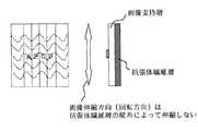
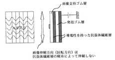
図2は、中間転写体として用いることのできる抗張体繊維層を説明するための図である。図2の左側に、ストレッチ加工前の、そして右側に、ストレッチ加工後の抗張体繊維層を示している。縦糸と横糸を織りあわせた抗張体繊維層(例えばコットン繊維)は、中間転写体としての伸縮剛性を上げるために、中間転写体画像の伸縮方向(回転方向)にストレッチ加工が施される。
【0016】
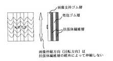
図3は、このような抗張体繊維層を中間転写体に配した構成を示す図である。上記の抗張体繊維層の上に、画像支持層を貼り付けることにより、中間転写体表面層が形成される。ストレッチ加工を施した繊維の縦糸によって画像の伸縮が抑えられて、高精度な画像重ねを行うことが可能となる。また、高価な高剛性材料(例えばポリイミド)を用いることがないので、安価な高剛性中間転写体を提供することが可能となる。
【0017】
図4は、図3に示した画像支持層として、弾性のあるゴム(JIS-A10度〜80度)を用いた構成を示す図である。このような構成により、感光ドラムとの接触が安定して確実な画像形成を行うことができる。これによって、弾性のあるゴムを用いても抗張体繊維層により画像伸縮が発生しないために、高精度で安定した画像形成を行うことが可能となる。
【0018】
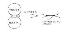
図5は、図4に示す中間転写体を用いた場合の感光ドラムとのニップ部の状態を示す図である。画像支持層として、弾性のあるゴムを用いた場合、接触の更なる安定化を図るために高付圧(約3kgf/cm2以上)をかけると、バルジと呼ばれる表面ゴム層のニップ局部における伸びが発生する場合がある。
【0019】
図6は、上記のバルジを抑えるために、発泡ゴム層を配した中間転写体を例示する図である。このように、ソリッドゴムから成る画像支持ゴム層の下に発泡ゴム層を配することで、発泡ゴムによりソリッドゴム層の伸びを吸収することができる。これによって、バルジの発生がなく、接触の更なる安定化を図るための高付圧(約3kgf/cm2以上)を加えることが可能となる。
【0020】
また、この発泡ゴム層は、発泡形態を気泡各々が連結していない(連続発泡ではない)独立発泡とすることにより、せん断方向の耐力が向上して安定した画像形成を行うことができる。
【0021】
図7は、発泡ゴム層を抗張体繊維層で挟んだ構成にした中間転写体を例示する図である。このような構成によって、発泡ゴム層のせん断方向の耐力が向上して、安定した画像形成を行うことができる。
【0022】
図8は、フッ素樹脂皮膜層を配した中間転写体を例示する図である。抗張体繊維層、前述の画像支持ゴム層、及び発泡ゴム層の材質を、フッ素樹脂(例えばPFA等)を焼成可能な耐熱を持った材料として、その表面にフッ素樹脂皮膜層を配することにより、表面エネルギが小さく媒体への転写効率に優れた中間転写体を提供することが可能となる。フッ素樹脂(例えばPFA等)が焼成可能な材料としては以下の例があげられる。耐熱繊維材料例:ポリアミド繊維、ビニロン繊維等、耐熱ゴム材料例:シリコーンゴム、アクリルゴム、NBRゴム等、耐熱発泡ゴム材料例:シリコーンゴム、アクリルゴム、NBRゴム等。
【0023】
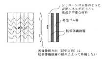
図9は、画像支持ゴム層として、シリコーンゴム等の表面エネルギが小さく焼成が不要な材料を配した中間転写体を例示する図である。抗張体繊維層及び発泡ゴム層に耐熱性の低い安価な材料を用いても、表面エネルギが小さく媒体への転写効率に優れた中間転写体を提供することが可能となる。
【0024】
図10は、画像支持ゴム層として、シリコーンゴムの硬化不良の原因となる硫黄成分を排除した成分構成とした中間転写体を例示する図である。このような構成によって、表面エネルギーの小さなシリコーンゴムの薄膜(数十μm)皮膜が可能となる。高価なシリコーンゴムの使用は表層の薄膜(数十μm)のみとなり安価で表面エネルギが小さく媒体への転写効率に優れた中間転写体を提供することが可能となる。
【0025】
図11は、図8に示したフッ素樹脂皮膜として、フッ素樹脂をフッ素ゴム中に分散したタイプの皮膜(例えばダイキン工業のGLS −213 )とした中間転写体を例示する図である。これによって、表面ラフ媒体での表面追従性に優れた中間転写体を提供することが可能となる。
【0026】
また、フッ素樹脂をフッ素ゴム中に分散したタイプの皮膜(例えばダイキン工業のGLS −213 )において100 ℃〜200 ℃の比較的低温で半焼成させることにより、高価な耐熱材料を用いることなく表面エネルギが小さく、また表面ラフ媒体での表面追従性に優れた安価な中間転写体の提供が可能となる。
【0027】
トナーを電気的クーロン力によって移動させる場合、中間転写体に電気抵抗を付与する必要がある。フッ素樹脂をフッ素ゴム中に分散したタイプの皮膜(例えばダイキン工業のGLS −213 )は、焼成温度及び焼成時間によってイオン導電性が変化し電気抵抗が変化する。そこで、100 ℃〜200 ℃の温度範囲で、焼成温度と焼成時間を調整管理することで、トナーの電気的クーロン力に適した電気抵抗108Ωcm〜1013Ωcmの半抵抗を持った表面エネルギが小さく、また表面ラフ媒体での表面追従性に優れた安価な中間転写体の提供が可能となる。
【0028】
図12は、導電層(低抵抗層)を配した中間転写体を例示する図である。上述のように、トナーを電気的クーロン力によって移動させる場合、中間転写体に電気抵抗を付与する必要がある。一般的に繊維層は絶縁性が高い。そこで感光ドラムとのニップ部で電気的クーロン力を確保するために、画像支持ゴム層をトナーの電気的クーロン力に適した電気抵抗108Ωcm〜1013Ωcmの半抵抗に設定し、更に画像支持層の下に中間転写体端部から電極を取れるように107Ωcm以下の低抵抗層を配する。この構造により繊維層が絶縁性でも、感光ドラムとのニップ部で電気的クーロン力を得ることができ、安定した転写を行うことが可能となる。
【0029】
図13は、導電層において中間転写体左右部から電極を取れるように配した中間転写体を例示する図である。本構造により中間転写体をシームレスの円筒体にすることができ画像を連続的に出力することが可能となる。
【0030】
図14は、抗張体繊維層に導電性を持った繊維を配した中間転写体を例示する図である。トナーを電気的クーロン力によって移動させる場合、中間転写体に電気抵抗を付与する必要がある。抗張体繊維層に導電性を持った繊維(例えばカーボン入り繊維もしくはステンレス入り繊維)を用いることで、中間転写体ニップ下部(中間転写ローラ支持ドラム)から直接電極を取ることができ、導電層が不要となり安価な中間転写体の提供が可能となる。
【0031】
一般的にカーボン入り繊維もしくはステンレス入り繊維等の導電性繊維は、耐伸縮特性が純粋な繊維に比べて劣りまた高価である。そこで、導電性を持った繊維を横糸のみに用いて、ストレッチを行う縦糸に純粋な繊維を用いることで、耐伸縮性の劣化がなく、導電性を持った安価な中間転写体を提供することが可能となる。
【0032】
また、導電性を持った繊維を横糸の数本に1本の割合で編み込むことにより、高価な導電性繊維の使用量が減り、安価な導電性を持った中間転写体を提供することが可能となる。
【0033】
図15は、数本の導電繊維を純粋な繊維で包みこんで1本の繊維としたタイプを例示する断面図である。導電繊維を純粋な繊維で包み込むことで、縦糸に使っても耐伸縮特性の劣化が少ない導電性を持った中間転写体を提供することが可能となる。
【0034】
また、導電性を持った抗張体繊維層を形成するために、溶剤揮発型導電性塗料に浸した繊維を用いることができる。この構成では、特殊な導電性繊維を用いる必要がないため、耐伸縮特性の劣化がない安価な導電性を持った中間転写体を提供することが可能となる。
【0035】
この溶剤揮発型導電性塗料は、中間転写体層形成後(製造後)に塗布する。層形成時は導電性繊維を扱うことがないために特殊な設備を必要とせず、溶剤揮発型導電性塗料は、繊維の毛管現象により均一に細部まで浸透し、容易に抵抗ムラのない安価な中間転写体を提供することが可能となる。
【0036】
【発明の効果】
本発明は、中間転写体の回転方向にストレッチ加工を施した抗張体繊維層を配して、中間転写体の伸縮剛性を上げると共に、その表面には画像支持層を配したものであるから、ポリイミド等の従来の高価な材料を用いた中間転写体と同等の機能を有しつつ、低コストで製造することができるという効果を生じる。
【図面の簡単な説明】
【図1】本発明を適用することのできる液体トナーを用いる電子写真装置の全体構成を示す図である。
【図2】中間転写体として用いることのできる抗張体繊維層を説明するための図である。
【図3】抗張体繊維層を中間転写体に配した構成を示す図である。
【図4】図3に示した画像支持層として、弾性のあるゴムを用いた構成を示す図である。
【図5】図4に示す中間転写体を用いた場合の感光ドラムとのニップ部の状態を示す図である。
【図6】バルジを抑えるために発泡ゴム層を配した中間転写体を例示する図である。
【図7】発泡ゴム層を抗張体繊維層で挟んだ構成にした中間転写体を例示する図である。
【図8】フッ素樹脂皮膜層を配した中間転写体を例示する図である。
【図9】画像支持ゴム層として、シリコーンゴム等の表面エネルギが小さく焼成が不要な材料を配した中間転写体を例示する図である。
【図10】画像支持ゴム層として、シリコーンゴムの硬化不良の原因となる硫黄成分を排除した成分構成とした中間転写体を例示する図である。
【図11】図8に示したフッ素樹脂皮膜において、フッ素樹脂をフッ素ゴム中に分散したタイプの皮膜とした中間転写体を例示する図である。
【図12】導電層(低抵抗層)を配した中間転写体を例示する図である。
【図13】導電層において中間転写体左右部から電極を取れるように配した中間転写体を例示する図である。
【図14】抗張体繊維層に導電性を持った繊維を配した中間転写体を例示する図である。
【図15】導電性を持った繊維に、導電繊維を純粋な繊維で包みこんだタイプの繊維を例示する断面図である。
【図16】従来技術の中間転写体構成を示す図である。[0001]
BACKGROUND OF THE INVENTION
The present invention relates to an intermediate transfer member of a color electrophotographic apparatus that can be constructed at low cost.
[0002]
[Prior art]
In a color electrophotographic apparatus, toner images of respective colors developed on a photoreceptor using liquid toners of a plurality of colors are transferred onto an intermediate transfer member and superimposed, and then transferred to a printing medium and fixed.
[0003]
As such an intermediate transfer member, for example, a configuration as shown in FIG. 16 is known (Japanese Patent Laid-Open No. 2000-56575). The intermediate transfer roller exemplified as the roller configuration is provided with a rigid drum made of metal such as aluminum at the center. This drum has conductivity so that a voltage can be applied from a shaft or the like in order to transfer a toner image on the photosensitive member onto the intermediate transfer member with electrostatic force. It has a hardness for applying a pressure necessary for melt transfer onto the medium. On this drum, there is provided an elastic layer having conductivity and heat resistance, and a highly rigid surface layer having conductivity, heat resistance, releasability, and preferably silicone oil resistance.
[0004]
As the high-rigidity surface layer, for example, a heat-resistant and conductive film of about 10 to 50 μm, or a conductive polyimide coated with fluorosilicone rubber has been used to reduce the expansion and contraction of the intermediate transfer member.
[0005]
However, conventionally, a high-rigidity material (for example, polyimide) used as a surface layer of an intermediate transfer member in a color electrophotographic apparatus has a problem that it is expensive.
[0006]
[Problems to be solved by the invention]
The present invention has been made in view of such circumstances, and an object of the present invention is to provide an inexpensive high-rigidity intermediate transfer member layer structure without using an expensive surface layer material in a color electrophotographic apparatus.
[0007]
[Means for Solving the Problems]
The intermediate transfer member of the color electrophotographic apparatus of the present invention transfers and superimposes the toner images of each color developed on the photoreceptor using a plurality of color liquid toners, and prints the toner images transferred and superimposed. It is for transferring to a medium. Then, a tensile fiber layer subjected to a stretch process in the rotational direction of the intermediate transfer member is disposed to increase the stretch rigidity of the intermediate transfer member, and an image support layer is disposed on the surfacethereof. Warp yarn that stretches by using electrically conductive fibers in the tensile fiber layer and directly conducting electrical conduction from the lower part of the intermediate transfer body nip, and using conductive fibers only for weft yarns. Is characterizedby using a fiber that does not impart conductivity necessary for electrical conduction .
[0008]
In the present invention, a foam rubber layer can be disposed on or below the tensile fiber layer.
[0009]
DETAILED DESCRIPTION OF THE INVENTION
Hereinafter, the present invention will be described in detail according to embodiments. FIG. 1 illustrates the overall configuration of an electrophotographic apparatus using liquid toner to which the present invention can be applied. As shown in the figure, the electrophotographic apparatus includes a photosensitive member, a charger, an exposure device, a developing device for each color (only two are shown), an intermediate transfer member IMR, and a backup roller as main components. .
[0010]
The charger charges the photoreceptor to about 700V. The exposure apparatus exposes the photoconductor using a laser beam having a wavelength of 780 nm, thereby forming an electrostatic latent image on the photoconductor in which the potential of the exposed portion is about 100V.
[0011]
The developing machine is usually provided in association with yellow / magenta / cyan / black, is biased at about 400 to 600 V (E1), has a toner viscosity of 400 to 4000 mPa · S, and a carrier viscosity of 20 cSt. Using the toner, a toner layer having a thickness of 2 to 3 μm is formed on the developing roller. The developing roller supplies toner particles that are positively charged to the photoconductor in accordance with the electric field between the photoconductor and the toner on the exposed portion (or unexposed portion) of the photoconductor that is charged to about 100V. Adhere particles.
[0012]
The intermediate transfer member IMR is biased to about −800 V (E2) and transfers the toner attached to the photosensitive member according to the electric field between the intermediate transfer member IMR and the photosensitive member. The intermediate transfer member IMR first transfers, for example, yellow toner attached to the photosensitive member, subsequently transfers magenta toner attached to the photosensitive member, and subsequently transfers cyan toner. Subsequently, the black toner is transferred.
[0013]
The toner attached to the intermediate transfer member IMR is heated and melted by a heating device (not shown). The backup roller transfers and fixes the toner on the melted intermediate transfer member IMR to the print medium.
[0014]
Hereinafter, the configuration that can be used as the intermediate transfer member will be described with reference to FIGS. 2 to 15, but the following configuration is not limited to the roller-shaped intermediate transfer member, but also in the belt shape. Can also be applied. When this exemplary configuration is used for a roller-shaped intermediate transfer member, it is used directly on a rigid drum made of a metal such as aluminum or as a surface layer provided on an elastic layer. be able to. When used as a belt-shaped intermediate transfer member, the illustrated configuration can be used as it is in a belt shape.
[0015]
FIG. 2 is a diagram for explaining a tensile fiber layer that can be used as an intermediate transfer member. The tensile body fiber layer before stretch processing is shown on the left side of FIG. 2 and after stretch processing on the right side. A tensile fiber layer (for example, cotton fiber) obtained by weaving warp and weft is stretched in the expansion / contraction direction (rotation direction) of the intermediate transfer body image in order to increase the expansion / contraction rigidity of the intermediate transfer body.
[0016]
FIG. 3 is a diagram showing a configuration in which such a tensile fiber layer is disposed on an intermediate transfer member. By pasting an image support layer on the above-mentioned tensile body fiber layer, an intermediate transfer member surface layer is formed. Expansion and contraction of the image is suppressed by the warp yarn of the stretched fiber, and it is possible to perform high-precision image overlay. In addition, since an expensive high-rigidity material (for example, polyimide) is not used, an inexpensive high-rigidity intermediate transfer member can be provided.
[0017]
FIG. 4 is a diagram showing a configuration using elastic rubber (JIS-A 10 to 80 degrees) as the image support layer shown in FIG. With such a configuration, the contact with the photosensitive drum can be stably performed and reliable image formation can be performed. As a result, even when elastic rubber is used, image expansion and contraction does not occur due to the tensile fiber layer, so that highly accurate and stable image formation can be performed.
[0018]
FIG. 5 is a diagram showing a state of the nip portion with the photosensitive drum when the intermediate transfer member shown in FIG. 4 is used. When elastic rubber is used as the image support layer, if high pressure (approx. 3kgf / cm2 or more) is applied to further stabilize the contact, the surface rubber layer called bulge will stretch at the nip area. May occur.
[0019]
FIG. 6 is a diagram illustrating an intermediate transfer member provided with a foam rubber layer in order to suppress the bulge. Thus, by disposing the foamed rubber layer under the image supporting rubber layer made of solid rubber, the elongation of the solid rubber layer can be absorbed by the foamed rubber. As a result, no bulge is generated, and it is possible to apply a high pressure (about 3 kgf / cm2 or more) for further stabilizing the contact.
[0020]
In addition, the foamed rubber layer is formed by independent foaming in which foams are not connected to each other (not continuous foaming), whereby the yield strength in the shear direction is improved and stable image formation can be performed.
[0021]
FIG. 7 is a diagram illustrating an intermediate transfer body having a configuration in which a foam rubber layer is sandwiched between tensile fiber layers. With such a configuration, the yield strength in the shearing direction of the foamed rubber layer is improved, and stable image formation can be performed.
[0022]
FIG. 8 is a diagram illustrating an intermediate transfer member provided with a fluororesin film layer. The material of the tensile fiber layer, the image supporting rubber layer, and the foamed rubber layer is made of a heat-resistant material capable of firing a fluororesin (eg, PFA), and a fluororesin film layer is disposed on the surface thereof. As a result, it is possible to provide an intermediate transfer body having a small surface energy and excellent transfer efficiency to a medium. Examples of materials that can be baked with a fluororesin (for example, PFA) include the following. Heat resistant fiber material examples: polyamide fiber, vinylon fiber, etc., heat resistant rubber material examples: silicone rubber, acrylic rubber, NBR rubber, etc., heat resistant foam rubber material examples: silicone rubber, acrylic rubber, NBR rubber, etc.
[0023]
FIG. 9 is a diagram illustrating an intermediate transfer member in which a material having a small surface energy, such as silicone rubber, that does not need to be fired is disposed as the image supporting rubber layer. Even if inexpensive materials with low heat resistance are used for the tensile fiber layer and the foamed rubber layer, it is possible to provide an intermediate transfer member having a small surface energy and excellent transfer efficiency to a medium.
[0024]
FIG. 10 is a diagram exemplifying an intermediate transfer member having a component structure in which a sulfur component that causes poor curing of silicone rubber is excluded as an image supporting rubber layer. With such a configuration, a thin film (several tens of μm) of silicone rubber having a small surface energy can be formed. Expensive silicone rubber is used only on the surface thin film (several tens of μm), and it is possible to provide an intermediate transfer member that is inexpensive, has low surface energy, and excellent transfer efficiency to a medium.
[0025]
FIG. 11 is a diagram illustrating an intermediate transfer member in which the fluororesin film shown in FIG. 8 is a type of film (for example, GLS-213 manufactured by Daikin Industries) in which a fluororesin is dispersed in fluororubber. As a result, it is possible to provide an intermediate transfer member excellent in surface followability on a surface rough medium.
[0026]
In addition, surface energy can be obtained without using expensive heat-resistant materials by semi-firing at a relatively low temperature of 100 ° C. to 200 ° C. in a film (for example, GLS-213 from Daikin Industries) in which a fluororesin is dispersed in fluoro rubber. It is possible to provide an inexpensive intermediate transfer member having a small surface roughness and excellent surface followability on a rough surface medium.
[0027]
When the toner is moved by an electric Coulomb force, it is necessary to give an electric resistance to the intermediate transfer member. In a film of a type in which a fluororesin is dispersed in fluororubber (for example, GLS-213 from Daikin Industries), the ionic conductivity changes depending on the baking temperature and baking time, and the electric resistance changes. Therefore, by adjusting and controlling the baking temperature and baking time in the temperature range of 100 ° C. to 200 ° C., the surface energy having a half resistance of108 Ωcm to1013 Ωcm suitable for the electric coulomb force of the toner. It is possible to provide an inexpensive intermediate transfer member having a small surface roughness and excellent surface followability on a rough surface medium.
[0028]
FIG. 12 is a diagram illustrating an intermediate transfer member provided with a conductive layer (low resistance layer). As described above, when the toner is moved by an electric Coulomb force, it is necessary to give an electric resistance to the intermediate transfer member. In general, the fiber layer is highly insulating. Therefore, in order to ensure the electric coulomb force at the nip portion with the photosensitive drum, the image supporting rubber layer is set to a half resistance of108 Ωcm to1013 Ωcm suitable for the electric coulomb force of the toner, and further the image. A low resistance layer of107 Ωcm or less is disposed under the support layer so that an electrode can be taken from the end of the intermediate transfer member. With this structure, even if the fiber layer is insulative, an electric coulomb force can be obtained at the nip portion with the photosensitive drum, and stable transfer can be performed.
[0029]
FIG. 13 is a diagram illustrating an intermediate transfer member arranged so that electrodes can be taken from the left and right portions of the intermediate transfer member in the conductive layer. With this structure, the intermediate transfer body can be a seamless cylindrical body, and images can be output continuously.
[0030]
FIG. 14 is a diagram illustrating an intermediate transfer member in which conductive fibers are arranged in a tensile fiber layer. When the toner is moved by an electric Coulomb force, it is necessary to give an electric resistance to the intermediate transfer member. By using conductive fibers (for example, carbon-containing fibers or stainless steel-containing fibers) for the tensile body fiber layer, the electrode can be directly taken from the lower part of the intermediate transfer body nip (intermediate transfer roller support drum). Therefore, an inexpensive intermediate transfer member can be provided.
[0031]
In general, conductive fibers such as carbon-filled fibers or stainless-filled fibers are inferior to and expensive in terms of stretch resistance. Therefore, by using a conductive fiber only for the weft and using a pure fiber for the warp to be stretched, there is no deterioration in stretch resistance, and an inexpensive intermediate transfer body having conductivity is provided. Is possible.
[0032]
In addition, by interweaving conductive fibers at a ratio of one to several weft yarns, the amount of expensive conductive fibers used can be reduced, and it is possible to provide an intermediate transfer body with low conductivity. It becomes.
[0033]
FIG. 15 is a cross-sectional view illustrating a type in which several conductive fibers are wrapped with pure fibers to form one fiber. By wrapping the conductive fibers with pure fibers, it is possible to provide an intermediate transfer body having conductivity with little deterioration of the stretch resistance even when used for warp.
[0034]
In addition, in order to form a tensile fiber layer having conductivity, fibers dipped in a solvent volatile conductive paint can be used. In this configuration, since it is not necessary to use special conductive fibers, it is possible to provide an inexpensive intermediate transfer body having no deterioration in stretch resistance.
[0035]
This solvent volatile conductive coating is applied after the intermediate transfer layer is formed (after production). Since the conductive fibers are not handled during layer formation, no special equipment is required, and the solvent volatile conductive paint penetrates evenly into the details due to the capillary action of the fibers, and it is easy and inexpensive without resistance unevenness. An intermediate transfer member can be provided.
[0036]
【The invention's effect】
In the present invention, a tensile fiber layer stretched in the rotation direction of the intermediate transfer member is disposed to increase the stretch rigidity of the intermediate transfer member, and an image support layer is disposed on the surface thereof. In addition, there is an effect that it can be manufactured at a low cost while having a function equivalent to that of an intermediate transfer member using a conventional expensive material such as polyimide.
[Brief description of the drawings]
FIG. 1 is a diagram showing an overall configuration of an electrophotographic apparatus using a liquid toner to which the present invention can be applied.
FIG. 2 is a diagram for explaining a tensile fiber layer that can be used as an intermediate transfer member.
FIG. 3 is a diagram showing a configuration in which a tensile fiber layer is disposed on an intermediate transfer member.
4 is a diagram showing a configuration in which elastic rubber is used as the image support layer shown in FIG. 3;
5 is a diagram showing a state of a nip portion with a photosensitive drum when the intermediate transfer member shown in FIG. 4 is used.
FIG. 6 is a diagram illustrating an intermediate transfer member provided with a foam rubber layer in order to suppress bulges.
FIG. 7 is a diagram illustrating an intermediate transfer member having a configuration in which a foam rubber layer is sandwiched between tensile fiber layers.
FIG. 8 is a diagram illustrating an intermediate transfer member provided with a fluororesin film layer.
FIG. 9 is a diagram illustrating an intermediate transfer member in which a material having a small surface energy, such as silicone rubber, that does not need to be fired is disposed as an image supporting rubber layer.
FIG. 10 is a diagram illustrating an intermediate transfer member having a component structure in which a sulfur component that causes poor curing of silicone rubber is excluded as an image supporting rubber layer.
11 is a diagram exemplifying an intermediate transfer member in which the fluororesin film shown in FIG. 8 is a film of a type in which a fluororesin is dispersed in fluororubber.
FIG. 12 is a diagram illustrating an intermediate transfer member provided with a conductive layer (low resistance layer).
FIG. 13 is a diagram illustrating an intermediate transfer member arranged so that electrodes can be taken from left and right portions of the intermediate transfer member in a conductive layer.
FIG. 14 is a diagram illustrating an intermediate transfer member in which conductive fibers are arranged in a tensile fiber layer.
FIG. 15 is a cross-sectional view illustrating a fiber of a type in which a conductive fiber is wrapped with pure fiber in a conductive fiber.
FIG. 16 is a diagram illustrating a configuration of an intermediate transfer member according to a conventional technique.
Claims (15)
Translated fromJapanese中間転写体の回転方向にストレッチ加工を施した抗張体繊維層を配して、中間転写体の伸縮剛性を上げると共に、その表面には画像支持層を配し、
前記抗張体繊維層に、導電性を持った繊維を用いることで中間転写体ニップ下部から直接電気的導通をとり、かつ、
前記導電性を持った繊維を横糸のみに用いて、ストレッチを行う縦糸には、電気的導通をとるのに必要な導電性を付与しない繊維を用いたカラー電子写真装置の中間転写体。Intermediate transfer of a color electrophotographic apparatus for transferring and superimposing toner images of respective colors developed on a photoreceptor using liquid toners of a plurality of colors and transferring the superimposed toner images onto a printing medium In the body,
A stretch fiber layer that is stretched in the rotational direction of the intermediate transfer member is arranged to increase the stretch rigidity of the intermediate transfer member, and an image support layer is provided on the surface thereof.
The tensile fiber layer is electrically conductive from the bottom of the intermediate transfer member nip by using conductive fibers, and
An intermediate transfer member for a color electrophotographic apparatus, wherein the conductive fibers are used only for weft yarns, and the warp yarns to be stretched are made of fibers that do not impart conductivity necessary for electrical continuity.
Priority Applications (4)
| Application Number | Priority Date | Filing Date | Title |
|---|---|---|---|
| JP2001104093AJP3802362B2 (en) | 2001-04-03 | 2001-04-03 | Intermediate transfer member for color electrophotographic apparatus |
| PCT/JP2002/003143WO2002082189A1 (en) | 2001-04-03 | 2002-03-29 | Transferring/fixing system of liquid developing electrophotographic system |
| EP02707242AEP1378801A4 (en) | 2001-04-03 | 2002-03-29 | SYSTEM FOR TRANSFER / FIXATION OF ELECTROPHOTOGRAPHIC LIQUID DEVELOPMENT SYSTEM |
| US10/344,927US6785501B2 (en) | 2001-04-03 | 2002-03-29 | Transfer-and-fixation system with preheated printing medium for creating images using liquid-development electrophotographic apparatus |
Applications Claiming Priority (1)
| Application Number | Priority Date | Filing Date | Title |
|---|---|---|---|
| JP2001104093AJP3802362B2 (en) | 2001-04-03 | 2001-04-03 | Intermediate transfer member for color electrophotographic apparatus |
Publications (2)
| Publication Number | Publication Date |
|---|---|
| JP2002304066A JP2002304066A (en) | 2002-10-18 |
| JP3802362B2true JP3802362B2 (en) | 2006-07-26 |
Family
ID=18957002
Family Applications (1)
| Application Number | Title | Priority Date | Filing Date |
|---|---|---|---|
| JP2001104093AExpired - Fee RelatedJP3802362B2 (en) | 2001-04-03 | 2001-04-03 | Intermediate transfer member for color electrophotographic apparatus |
Country Status (1)
| Country | Link |
|---|---|
| JP (1) | JP3802362B2 (en) |
Families Citing this family (33)
| Publication number | Priority date | Publication date | Assignee | Title |
|---|---|---|---|---|
| JP4486313B2 (en)* | 2003-03-31 | 2010-06-23 | 株式会社明治ゴム化成 | Image transfer sheet |
| US7865091B2 (en) | 2007-01-10 | 2011-01-04 | Kabushiki Kaisha Toshiba | Image forming apparatus having a transfer surface with elasticity and image forming method |
| US7853188B2 (en) | 2007-01-10 | 2010-12-14 | Kabushiki Kaisha Toshiba | Image forming apparatus and image forming method |
| US10632740B2 (en) | 2010-04-23 | 2020-04-28 | Landa Corporation Ltd. | Digital printing process |
| US9902147B2 (en) | 2012-03-05 | 2018-02-27 | Landa Corporation Ltd. | Digital printing system |
| US9643403B2 (en) | 2012-03-05 | 2017-05-09 | Landa Corporation Ltd. | Printing system |
| US10642198B2 (en) | 2012-03-05 | 2020-05-05 | Landa Corporation Ltd. | Intermediate transfer members for use with indirect printing systems and protonatable intermediate transfer members for use with indirect printing systems |
| US9498946B2 (en) | 2012-03-05 | 2016-11-22 | Landa Corporation Ltd. | Apparatus and method for control or monitoring of a printing system |
| JP6437312B2 (en) | 2012-03-05 | 2018-12-12 | ランダ コーポレイション リミテッド | Digital printing process |
| US10569534B2 (en) | 2012-03-05 | 2020-02-25 | Landa Corporation Ltd. | Digital printing system |
| HK1204640A1 (en) | 2012-03-05 | 2015-11-27 | Landa Corporation Ltd. | Ink film constructions |
| US10434761B2 (en) | 2012-03-05 | 2019-10-08 | Landa Corporation Ltd. | Digital printing process |
| EP2825486B1 (en) | 2012-03-15 | 2019-01-02 | Landa Corporation Ltd. | Endless flexible belt for a printing system |
| GB201401173D0 (en) | 2013-09-11 | 2014-03-12 | Landa Corp Ltd | Ink formulations and film constructions thereof |
| GB2536489B (en) | 2015-03-20 | 2018-08-29 | Landa Corporation Ltd | Indirect printing system |
| GB2537813A (en) | 2015-04-14 | 2016-11-02 | Landa Corp Ltd | Apparatus for threading an intermediate transfer member of a printing system |
| US10933661B2 (en) | 2016-05-30 | 2021-03-02 | Landa Corporation Ltd. | Digital printing process |
| GB201609463D0 (en) | 2016-05-30 | 2016-07-13 | Landa Labs 2012 Ltd | Method of manufacturing a multi-layer article |
| US10926532B2 (en) | 2017-10-19 | 2021-02-23 | Landa Corporation Ltd. | Endless flexible belt for a printing system |
| US11267239B2 (en) | 2017-11-19 | 2022-03-08 | Landa Corporation Ltd. | Digital printing system |
| US11511536B2 (en) | 2017-11-27 | 2022-11-29 | Landa Corporation Ltd. | Calibration of runout error in a digital printing system |
| US11707943B2 (en) | 2017-12-06 | 2023-07-25 | Landa Corporation Ltd. | Method and apparatus for digital printing |
| WO2019111223A1 (en) | 2017-12-07 | 2019-06-13 | Landa Corporation Ltd. | Digital printing process and method |
| CN117885446A (en) | 2018-06-26 | 2024-04-16 | 兰达公司 | Intermediate transmission components of digital printing systems |
| US10994528B1 (en) | 2018-08-02 | 2021-05-04 | Landa Corporation Ltd. | Digital printing system with flexible intermediate transfer member |
| US12001902B2 (en) | 2018-08-13 | 2024-06-04 | Landa Corporation Ltd. | Correcting distortions in digital printing by implanting dummy pixels in a digital image |
| WO2020075012A1 (en) | 2018-10-08 | 2020-04-16 | Landa Corporation Ltd. | Friction reduction means for printing systems and method |
| CN116080260A (en) | 2018-12-24 | 2023-05-09 | 兰达公司 | Digital printing system and method |
| US12358277B2 (en) | 2019-03-31 | 2025-07-15 | Landa Corporation Ltd. | Systems and methods for preventing or minimizing printing defects in printing processes |
| JP7685995B2 (en) | 2019-11-25 | 2025-05-30 | ランダ コーポレイション リミテッド | Drying of ink in digital printing using infrared radiation absorbed by particles embedded within an ITM |
| US11321028B2 (en) | 2019-12-11 | 2022-05-03 | Landa Corporation Ltd. | Correcting registration errors in digital printing |
| JP7657229B2 (en) | 2019-12-29 | 2025-04-04 | ランダ コーポレイション リミテッド | Printing method and system |
| EP4264377A4 (en) | 2021-02-02 | 2024-11-13 | Landa Corporation Ltd. | REDUCING DISTORTIONS IN PRINTED IMAGES |
Family Cites Families (4)
| Publication number | Priority date | Publication date | Assignee | Title |
|---|---|---|---|---|
| JP2563922B2 (en)* | 1987-04-06 | 1996-12-18 | 株式会社 金陽社 | Rubber blanket for printing |
| JPH06219078A (en)* | 1993-01-28 | 1994-08-09 | Fujikura Rubber Ltd | Printing blanket |
| JP2857017B2 (en)* | 1993-04-12 | 1999-02-10 | 春季 辻川 | Rubber blanket for printing |
| US6551716B1 (en)* | 1997-06-03 | 2003-04-22 | Indigo N.V. | Intermediate transfer blanket and method of producing the same |
- 2001
- 2001-04-03JPJP2001104093Apatent/JP3802362B2/ennot_activeExpired - Fee Related
Also Published As
| Publication number | Publication date |
|---|---|
| JP2002304066A (en) | 2002-10-18 |
Similar Documents
| Publication | Publication Date | Title |
|---|---|---|
| JP3802362B2 (en) | Intermediate transfer member for color electrophotographic apparatus | |
| US5335054A (en) | Image transfer apparatus including intermediate transfer blanket | |
| US5047808A (en) | Image transfer apparatus including a compliant transfer member | |
| US5089856A (en) | Image transfer apparatus incorporating an internal heater | |
| US6173147B1 (en) | Wet type electrophotography apparatus to heat toner on intermediate transfer medium | |
| US7294810B1 (en) | Heater, fixing device and image forming apparatus | |
| US9217971B1 (en) | Fixing device, heating member, and image forming apparatus | |
| US20150338806A1 (en) | Heater and image heating apparatus including the same | |
| JP2001022186A (en) | Electrophotographic device of liquid toner developing type | |
| JP2008090116A5 (en) | ||
| US6785501B2 (en) | Transfer-and-fixation system with preheated printing medium for creating images using liquid-development electrophotographic apparatus | |
| JP2003302852A (en) | Fixing device | |
| US7106997B2 (en) | Intermediate transfer member for carrying intermediate electrophotographic image | |
| JP3086858B2 (en) | Image transfer apparatus and method | |
| JP4244837B2 (en) | Image forming apparatus | |
| JP3411959B2 (en) | Wet electrophotographic equipment | |
| JP6425526B2 (en) | Fixing device and image forming apparatus provided with the same | |
| JP2008090113A (en) | Image forming apparatus and image forming method | |
| JP2001092268A (en) | Image-forming device | |
| JP2004021081A (en) | Fixing device | |
| JP2009098475A (en) | Fixing device, image forming apparatus using the same, and image forming method | |
| JP2000194220A (en) | Fixing device | |
| JP4143250B2 (en) | Image fixing apparatus, image fixing method, image forming apparatus, and image forming method | |
| JP2007322490A (en) | Image forming apparatus | |
| JP2003005491A (en) | Image forming device |
Legal Events
| Date | Code | Title | Description |
|---|---|---|---|
| A621 | Written request for application examination | Free format text:JAPANESE INTERMEDIATE CODE: A621 Effective date:20040116 | |
| A131 | Notification of reasons for refusal | Free format text:JAPANESE INTERMEDIATE CODE: A131 Effective date:20060124 | |
| A521 | Request for written amendment filed | Free format text:JAPANESE INTERMEDIATE CODE: A523 Effective date:20060208 | |
| A131 | Notification of reasons for refusal | Free format text:JAPANESE INTERMEDIATE CODE: A131 Effective date:20060307 | |
| A521 | Request for written amendment filed | Free format text:JAPANESE INTERMEDIATE CODE: A523 Effective date:20060328 | |
| TRDD | Decision of grant or rejection written | ||
| A01 | Written decision to grant a patent or to grant a registration (utility model) | Free format text:JAPANESE INTERMEDIATE CODE: A01 Effective date:20060425 | |
| A61 | First payment of annual fees (during grant procedure) | Free format text:JAPANESE INTERMEDIATE CODE: A61 Effective date:20060427 | |
| R150 | Certificate of patent or registration of utility model | Free format text:JAPANESE INTERMEDIATE CODE: R150 | |
| FPAY | Renewal fee payment (event date is renewal date of database) | Free format text:PAYMENT UNTIL: 20120512 Year of fee payment:6 | |
| LAPS | Cancellation because of no payment of annual fees |