JP3800941B2 - Electronic watch - Google Patents
Electronic watchDownload PDFInfo
- Publication number
- JP3800941B2 JP3800941B2JP2000292151AJP2000292151AJP3800941B2JP 3800941 B2JP3800941 B2JP 3800941B2JP 2000292151 AJP2000292151 AJP 2000292151AJP 2000292151 AJP2000292151 AJP 2000292151AJP 3800941 B2JP3800941 B2JP 3800941B2
- Authority
- JP
- Japan
- Prior art keywords
- cover member
- antenna
- recess
- case
- bezel
- Prior art date
- Legal status (The legal status is an assumption and is not a legal conclusion. Google has not performed a legal analysis and makes no representation as to the accuracy of the status listed.)
- Expired - Fee Related
Links
Images


Classifications
- G—PHYSICS
- G04—HOROLOGY
- G04G—ELECTRONIC TIME-PIECES
- G04G17/00—Structural details; Housings
- G04G17/08—Housings
- G—PHYSICS
- G04—HOROLOGY
- G04B—MECHANICALLY-DRIVEN CLOCKS OR WATCHES; MECHANICAL PARTS OF CLOCKS OR WATCHES IN GENERAL; TIME PIECES USING THE POSITION OF THE SUN, MOON OR STARS
- G04B37/00—Cases
- G04B37/12—Cases for special purposes, e.g. watch combined with ring, watch combined with button
- G—PHYSICS
- G04—HOROLOGY
- G04G—ELECTRONIC TIME-PIECES
- G04G21/00—Input or output devices integrated in time-pieces
- G04G21/04—Input or output devices integrated in time-pieces using radio waves
- G—PHYSICS
- G04—HOROLOGY
- G04R—RADIO-CONTROLLED TIME-PIECES
- G04R60/00—Constructional details
- G04R60/06—Antennas attached to or integrated in clock or watch bodies
- G—PHYSICS
- G04—HOROLOGY
- G04R—RADIO-CONTROLLED TIME-PIECES
- G04R60/00—Constructional details
- G04R60/06—Antennas attached to or integrated in clock or watch bodies
- G04R60/08—Antennas attached to or integrated in clock or watch bodies inside bezels
Landscapes
- Physics & Mathematics (AREA)
- General Physics & Mathematics (AREA)
- Electric Clocks (AREA)
- Electromechanical Clocks (AREA)
Description
Translated fromJapanese【0001】
【発明の属する技術分野】
この発明は電子腕時計に関する。
【0002】
【従来の技術】
従来、電子腕時計においては、アンテナを内蔵した電波時計がある。この種の電子時計は、図6に示すように、合成樹脂製の腕時計ケース1を備えている。この腕時計ケース1には、12時側と6時側(同図では12時側のみを示す)との箇所にバンド取付部2がそれぞれ設けられており、これらバンド取付部2のうち、12時側のバンド取付部2には、収納凹部3が上面側に向けて開放されて設けられている。この収納凹部3内には、アンテナ4が収納されている。このアンテナ4は、鉄芯であるコアにコイルを巻き付けたバーアンテナであり、その全外周にゴムシートなどの緩衝材6が巻き付けられている。また、収納凹部3の上部には、アンテナ4を覆うカバー部材5が固着されている。このカバー部材5は、合成樹脂製のパネルであり、その全周囲が超音波などの溶着により収納凹部3の上部に固着されている。
【0003】
なお、この腕時計ケース1の上面における外周部には、ベゼル7がカバー部材5との間に位置した状態で装着されている。また、この腕時計ケース1の上面における中央部分には、時計ガラス8が溶着により装着されており、腕時計ケース1の内部には、時計モジュール9が収納されている。この時計モジュール9は、アナログ機能とデジタル機能とのうち、少なくとも一方の機能を備え、腕時計ケース1の収納凹部3に収納されたアンテナ4が電気的に接続されている。さらに、腕時計ケース1の下面には、裏蓋10が防水リング10aを介して取り付けられている。
【0004】
【発明が解決しようとする課題】
しかしながら、このような電子腕時計では、アンテナ4を覆うカバー部材5の外面全体が腕時計ケース1の上面に露出しているので、図7に示すように、時計ガラス7を下側にして腕時計ケース1を誤って落下させたときに、アンテナ4の重みにより、アンテナ4側が低くなるように腕時計ケース1が傾いて落下し、この状態でカバー部材5の外面が床などに衝突するため、カバー部材5が直接衝撃を受け、カバー部材5の溶着部分にクラックが発生して破損するという問題がある。
また、この電子腕時計では、アンテナ4に緩衝材6を巻き付けておかないと、衝撃からアンテナ4を保護することができないという問題もある。なお、このようにアンテナ4に緩衝材6を巻き付けると、アンテナ4全体が大きくなり、これに伴って収納凹部3も大きく形成しなければならず、腕時計全体が大型化するという問題も生じる。
【0005】
この発明の課題は、落下などの衝撃によってカバー部材が破損しないようにすることである。
【0006】
【課題を解決するための手段】
この発明の電子腕時計は、上面中央部に時計ガラスが設けられると共に、12時及び6時方向にバンド取付部が延出形成され、かつ12時側バンド取付部に収納凹部及び係止凹部が形成された腕時計ケースと、前記収納凹部に収納されるアンテナと、このアンテナを覆って前記収納凹部に固着されたカバー部材と、前記腕時計ケースの上面外周部に装着され、前記カバー部材の少なくとも一部を覆って押える押え部が突出形成され、かつ、この押え部の先端が腕時計ケースに形成された係止凹部に係止されてなるベゼルとを備えたことを特徴とする。この発明によれば、アンテナが収納された収納凹部に固着されたカバー部材の少なくとも一部を、腕時計ケースに取り付けられた外装部材の押え部で覆って押えているので、この押え部によって落下などによる衝撃を受け止めることができ、これにより落下などの衝撃によってカバー部材が破損しないように、カバー部材を保護することができる。
【0007】
この場合、請求項2に記載のごとく、前記カバー部材と前記押え部との間に緩衝材が設けられていることにより、この緩衝材によって落下などによる衝撃を緩和することができ、これによっても落下などの衝撃からカバー部材および収納凹部に収納されたアンテナを保護することができ、また従来例のようにアンテナに緩衝材を巻き付ける必要がないため、アンテナ全体が大きくならず、これにより時計全体の小型化をも図ることができる。
【0008】
【発明の実施の形態】
以下、図1〜図4を参照して、この発明の電子腕時計の第1実施形態について説明する。なお、図6および図7に示された従来例と同一部分には同一符号を付して説明する。
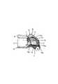
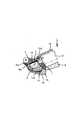
この電子腕時計は、図1および図2に示すように、合成樹脂製の腕時計ケース1の12時側に位置するバンド取付部2にアンテナ取付部11が9時側(図2では左側)に少し突出して設けられている。このアンテナ取付部11には、図3に示すように、アンテナ4を収納する収納凹部12が上面側に開放されて設けられている。この場合、アンテナ4は、両面接着テープ13によって収納凹部12内に接着されている。この収納凹部12の上部には、アンテナ4を覆うカバー部材14が固定されている。このカバー部材14も、従来例と同様、合成樹脂製のパネルであり、上面が山形状に厚く形成され、下面側が開放された箱蓋形状に形成され、その全周縁部が超音波などの溶着により収納凹部12に固着されている。
【0009】
また、腕時計ケース1の上面における外周部には、図1に示すように、外装部材であるベゼル15が装着されている。このベゼル15には、収納凹部12に固着されたカバー部材14の3時側(図1では右側)のほぼ半分程度を覆って押える押え部16が突出して形成されている。この場合、カバー部材14の上面には、図2に示すように、押え部16に対応する凹溝14aが浅く形成されている。また、押え部16は、図3に示すように、ベゼル15側に位置する基端部の肉厚が厚く、先端側の肉厚が薄く形成されており、この押え部16の先端部16aは、収納凹部12に形成された係止凹部12aに挿入して係止されている。さらに、この押え部16とカバー部材14との間には、図3に示すように、ゴムシートなどの緩衝材17が設けられている。この場合には、カバー部材14の凹溝14a内における最上面の箇所に平坦面14bが形成されており、この平坦面14bに緩衝材17が接着され、この状態で緩衝材17がベゼル15の押え部16によって押えられている。
【0010】
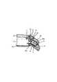
このような電子腕時計では、アンテナ4が収納された収納凹部12に固着されたカバー部材14の一部、つまりカバー部材14の右側のほぼ半分程度を、腕時計ケース1の外周部に取り付けられたベゼル15の押え部16で覆って押えているので、図4に示すように、腕時計ケース1がその時計ガラス7を下側にして落下したとき、アンテナ4の重みによってアンテナ4側が低くなるように、腕時計ケース1が傾いても、ベゼル15の押え部16によって落下などによる衝撃を受け止めることができ、これにより落下などの衝撃によってカバー部材14の溶着部分にクラックが発生して破損しないように、カバー部材14を保護することができる。
【0011】
この場合、カバー部材14と押え部16との間に緩衝材17が設けられているので、この緩衝材17によって落下などによる衝撃を緩和することができ、これによりカバー部材14および収納凹部12に収納されたアンテナ4を保護することができる。このため、従来例のようにアンテナ4に緩衝材6を巻き付ける必要がないので、アンテナ4全体が大きくならず、これに伴って収納凹部12も大きく形成する必要がないので、時計全体の小型化をも図ることができる。
【0012】
次に、図5を参照して、この発明の電子腕時計の第2実施形態について説明する。この場合には、図1〜図4に示された第1実施形態と同一部分には同一符号を付して説明する。
この電子腕時計は、アンテナ4を覆って収納凹部12に固着されるカバー部材20と、このカバー部材20の一部を覆って押えるベゼル15の押え部21との形状がそれぞれ第1実施形態と異なり、これ以外は第1実施形態とほぼ同じ構造になっている。
【0013】
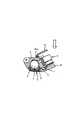
すなわち、カバー部材20は、合成樹脂製のパネルであり、全体の肉厚が厚く形成されている。このカバー部材20の下面には、アンテナ4の上部が挿入する凹部20aが形成されており、カバー部材20のベゼル15側に位置する上面には、切欠凹部22が設けられている。また、ベゼル15の押え部21は、ベゼル15の12時側の外周部から突出して設けられ、カバー部材20の切欠凹部22内に配置されてカバー部材14を上方から押え付けている。この場合にも、ベゼル15の押え部21とカバー部材20の切欠凹部22との間には、ゴムシートなどの緩衝材17が設けられている。
【0014】
このような電子腕時計では、アンテナ4が収納された収納凹部12に固着されたカバー部材20に切欠凹部22を設け、この切欠凹部22に腕時計ケース1の外周部に取り付けられたベゼル15の押え部21を配置させてカバー部材20を上方から押え付けているので、この押え部21によって落下などの衝撃をある程度受け止めることができ、これにより落下などの衝撃によってカバー部材20の溶着部分にクラックが発生して破損しないように、カバー部材20を保護することができる。この場合にも、カバー部材20の切欠凹部22と押え部21との間に緩衝材17が設けられているので、この緩衝材17によっても落下などの衝撃を緩和することができ、これによりカバー部材20およびアンテナ4を保護することができ、第1実施形態と同様、時計全体の小型化をも図ることができる。
【0015】
【発明の効果】
以上説明したように、この発明によれば、アンテナが収納された収納凹部に固着されたカバー部材の少なくとも一部を、腕時計ケースに取り付けられた外装部材の押え部で覆って押えているので、この押え部によって落下などによる衝撃を受け止めることができ、これにより落下などの衝撃によってカバー部材が破損しないように、カバー部材を保護することができる。
この場合、カバー部材と押え部との間に緩衝材を設けることにより、この緩衝材によって落下などによる衝撃を緩和することができ、これによっても落下などの衝撃からカバー部材および収納凹部に収納されたアンテナを保護することができ、また従来例のようにアンテナに緩衝材を巻き付ける必要がないため、アンテナ全体が大きくならず、これにより時計全体の小型化をも図ることができる。
【図面の簡単な説明】
【図1】この発明の電子腕時計の第1実施形態を示した正面図。
【図2】図1の腕時計ケースからベゼルを取り外した状態の要部の正面図。
【図3】図1のA−A矢視における拡大断面図。
【図4】図3の状態の腕時計を落下したときの状態を示した要部の拡大断面図。
【図5】この発明の電子腕時計の第2実施形態を示した要部の拡大断面図。
【図6】従来の電子腕時計を示した要部の拡大断面図。
【図7】図6の従来の腕時計を落下したときの状態を示した断面図。
【符号の説明】
1 腕時計ケース
4 アンテナ
12 収納凹部
14、20 カバー部材
15 ベゼル
16、21 押え部
17 緩衝材[0001]
BACKGROUND OF THE INVENTION
The present invention relates to an electronic wristwatch.
[0002]
[Prior art]
Conventionally, there is a radio timepiece with an antenna built in an electronic wristwatch. This type of electronic timepiece includes a
[0003]
A
[0004]
[Problems to be solved by the invention]
However, in such an electronic wristwatch, since the entire outer surface of the
In addition, this electronic wristwatch also has a problem that the
[0005]
An object of the present invention is to prevent the cover member from being damaged by an impact such as dropping.
[0006]
[Means for Solving the Problems]
The electronic wristwatch according to the present invention is provided with a watch glass at the center of the upper surface, a band attaching portion extendingat 12 o'clock and6 o'clock , and a storage recess and a locking recess being formed at the 12 o'clock side band attaching portion. A wristwatch case, an antenna housed in the housing recess, a cover member that covers the antenna and is fixed to the housing recess, and is attached to the outer periphery of the upper surface of the watch case, and is at least a part of the cover member And a bezel formed by protruding a presser portion that covers and presses the front end of the presser portion, and a bezel that is locked to a locking recess formed in the watch case. According to the present invention, since at least a part of the cover member fixed to the housing concave portion in which the antenna is housed is covered and pressed by the pressing portion of the exterior member attached to the watch case, it is dropped by this pressing portion. Thus, the cover member can be protected so that the cover member is not damaged by an impact such as dropping.
[0007]
In this case, as described in
[0008]
DETAILED DESCRIPTION OF THE INVENTION
A first embodiment of an electronic wristwatch according to the present invention will be described below with reference to FIGS. The same parts as those in the conventional example shown in FIG. 6 and FIG.
As shown in FIG. 1 and FIG. 2, the electronic wristwatch has a
[0009]
Further, as shown in FIG. 1, a
[0010]
In such an electronic wristwatch, a part of the
[0011]
In this case, since the
[0012]
Next, a second embodiment of the electronic wrist watch according to the present invention will be described with reference to FIG. In this case, the same parts as those in the first embodiment shown in FIGS.
This electronic wristwatch is different from the first embodiment in the shapes of the
[0013]
That is, the
[0014]
In such an electronic wristwatch, a
[0015]
【The invention's effect】
As described above, according to the present invention, at least a part of the cover member fixed to the storage recess in which the antenna is stored is covered and pressed by the pressing portion of the exterior member attached to the watch case. By this holding part, it is possible to receive an impact caused by dropping or the like, and thus it is possible to protect the cover member so that the cover member is not damaged by an impact such as dropping.
In this case, by providing a cushioning material between the cover member and the presser part, it is possible to mitigate the impact caused by dropping or the like by this cushioning material. The antenna can be protected, and it is not necessary to wrap a cushioning material around the antenna as in the conventional example. Therefore, the entire antenna is not enlarged, and thus the entire watch can be reduced in size.
[Brief description of the drawings]
FIG. 1 is a front view showing a first embodiment of an electronic wristwatch according to the present invention.
2 is a front view of a main part in a state where a bezel is removed from the watch case of FIG. 1; FIG.
3 is an enlarged cross-sectional view taken along the line AA in FIG.
4 is an enlarged cross-sectional view of a main part showing a state when the wristwatch in the state of FIG. 3 is dropped.
FIG. 5 is an enlarged cross-sectional view of the main part showing a second embodiment of the electronic wristwatch of the present invention.
FIG. 6 is an enlarged cross-sectional view of a main part showing a conventional electronic wristwatch.
7 is a cross-sectional view showing a state when the conventional wristwatch of FIG. 6 is dropped.
[Explanation of symbols]
DESCRIPTION OF
Claims (2)
Translated fromJapanese前記収納凹部に収納されるアンテナと、
このアンテナを覆って前記収納凹部に固着されたカバー部材と、
前記腕時計ケースの上面外周部に装着され、前記カバー部材の少なくとも一部を覆って押える押え部が突出形成され、かつ、この押え部の先端が腕時計ケースに形成された係止凹部に係止されてなるベゼルとを備えたことを特徴とする電子腕時計。A watch case provided with a watch glass in the center of the upper surface, a band attaching portion extending in the 12 o'clock and6 o'clock directions , and a storage recess and a locking recess formed in the 12 o'clock side band attaching portion;
An antenna housed in the housing recess;
A cover member that covers the antenna and is fixed to the storage recess;
A presser part that is mounted on the outer periphery of the upper surface of the watch case and covers and covers at least a part of the cover member is formed to protrude, and the tip of the presser part is locked to a locking recess formed in the watch case. An electronic wristwatch characterized by comprising a bezel.
Priority Applications (6)
| Application Number | Priority Date | Filing Date | Title |
|---|---|---|---|
| JP2000292151AJP3800941B2 (en) | 2000-09-26 | 2000-09-26 | Electronic watch |
| US09/961,857US6657922B2 (en) | 2000-09-26 | 2001-09-24 | Electronic watch |
| KR10-2001-0059223AKR100444187B1 (en) | 2000-09-26 | 2001-09-25 | Electronic watch |
| CNB011313471ACN1153104C (en) | 2000-09-26 | 2001-09-26 | electronic watch |
| TW090123723ATW490601B (en) | 2000-09-26 | 2001-09-26 | Electronic watch |
| HK02107927.1AHK1046555B (en) | 2000-09-26 | 2002-10-31 | Electronic watch |
Applications Claiming Priority (1)
| Application Number | Priority Date | Filing Date | Title |
|---|---|---|---|
| JP2000292151AJP3800941B2 (en) | 2000-09-26 | 2000-09-26 | Electronic watch |
Publications (2)
| Publication Number | Publication Date |
|---|---|
| JP2002098780A JP2002098780A (en) | 2002-04-05 |
| JP3800941B2true JP3800941B2 (en) | 2006-07-26 |
Family
ID=18775127
Family Applications (1)
| Application Number | Title | Priority Date | Filing Date |
|---|---|---|---|
| JP2000292151AExpired - Fee RelatedJP3800941B2 (en) | 2000-09-26 | 2000-09-26 | Electronic watch |
Country Status (6)
| Country | Link |
|---|---|
| US (1) | US6657922B2 (en) |
| JP (1) | JP3800941B2 (en) |
| KR (1) | KR100444187B1 (en) |
| CN (1) | CN1153104C (en) |
| HK (1) | HK1046555B (en) |
| TW (1) | TW490601B (en) |
Families Citing this family (17)
| Publication number | Priority date | Publication date | Assignee | Title |
|---|---|---|---|---|
| DE60223723T2 (en)* | 2001-12-14 | 2008-10-30 | Mbbs S.A. | WATCH HOUSING |
| JP2005098975A (en)* | 2003-09-01 | 2005-04-14 | Casio Comput Co Ltd | Watch case |
| JP4015104B2 (en)* | 2003-11-27 | 2007-11-28 | カシオ計算機株式会社 | Antenna device and clock |
| CN100440078C (en)* | 2003-12-02 | 2008-12-03 | 卡西欧计算机株式会社 | radio controlled watch |
| JP2006234436A (en)* | 2005-02-22 | 2006-09-07 | Seiko Instruments Inc | Radio controlled timepiece |
| JP2006284235A (en)* | 2005-03-31 | 2006-10-19 | Casio Comput Co Ltd | Arm-mounted electronic device |
| US7317425B2 (en) | 2005-03-31 | 2008-01-08 | Casio Computer Co., Ltd. | Antenna device and a method of making the antenna |
| WO2008007783A1 (en)* | 2006-07-13 | 2008-01-17 | Citizen Holdings Co., Ltd. | Clock with wireless function |
| JP5493527B2 (en)* | 2009-07-14 | 2014-05-14 | セイコーエプソン株式会社 | Clock with wireless function |
| US9231306B2 (en)* | 2012-09-20 | 2016-01-05 | Casio Computer Co., Ltd. | Patch antenna and wireless communications device |
| JP6323023B2 (en)* | 2014-01-21 | 2018-05-16 | セイコーエプソン株式会社 | clock |
| JP6020494B2 (en)* | 2014-03-13 | 2016-11-02 | カシオ計算機株式会社 | Band mounting structure and watch |
| CN106461416B (en)* | 2014-04-29 | 2019-08-06 | 卡姆鲁普股份有限公司 | Consumption meter with antenna |
| TWM502861U (en)* | 2015-03-02 | 2015-06-11 | Quanta Comp Inc | Wearable electronic device |
| JP6723522B2 (en)* | 2017-07-27 | 2020-07-15 | カシオ計算機株式会社 | Case and clock |
| KR102070054B1 (en)* | 2018-04-13 | 2020-01-28 | 오영권 | Wrist watch on which bezel is mounted and separated using lug |
| CN114430813A (en)* | 2019-09-24 | 2022-05-03 | Eta瑞士钟表制造股份有限公司 | Middle part-ear connection for a watch case |
Family Cites Families (8)
| Publication number | Priority date | Publication date | Assignee | Title |
|---|---|---|---|---|
| JPS56148090A (en)* | 1980-04-18 | 1981-11-17 | Citizen Watch Co Ltd | Liquid cell supporting structure of electronic watch |
| JPS5750681A (en)* | 1980-09-12 | 1982-03-25 | Citizen Watch Co Ltd | Modular structure for electronic timepiece |
| CH672870B5 (en)* | 1988-04-26 | 1990-07-13 | Ebauchesfabrik Eta Ag | |
| JP3134377B2 (en)* | 1991-03-08 | 2001-02-13 | カシオ計算機株式会社 | Small electronic devices with sensors |
| JP3143198B2 (en)* | 1992-02-07 | 2001-03-07 | シチズン時計株式会社 | Watch case structure of radio clock |
| CH686990B5 (en)* | 1994-12-20 | 1997-02-28 | Breitling Montres Sa | Wristwatch with high-frequency transmitter. |
| FR2775809B1 (en)* | 1998-03-09 | 2002-06-14 | Finaluxe | BRACELET WITH MEANS FOR IDENTIFYING IT |
| KR100313144B1 (en)* | 1998-11-27 | 2001-11-07 | 윤종용 | Watch type portable radiotelephone |
- 2000
- 2000-09-26JPJP2000292151Apatent/JP3800941B2/ennot_activeExpired - Fee Related
- 2001
- 2001-09-24USUS09/961,857patent/US6657922B2/ennot_activeExpired - Lifetime
- 2001-09-25KRKR10-2001-0059223Apatent/KR100444187B1/ennot_activeExpired - Fee Related
- 2001-09-26TWTW090123723Apatent/TW490601B/ennot_activeIP Right Cessation
- 2001-09-26CNCNB011313471Apatent/CN1153104C/ennot_activeExpired - Lifetime
- 2002
- 2002-10-31HKHK02107927.1Apatent/HK1046555B/ennot_activeIP Right Cessation
Also Published As
| Publication number | Publication date |
|---|---|
| KR100444187B1 (en) | 2004-08-16 |
| KR20020024792A (en) | 2002-04-01 |
| CN1153104C (en) | 2004-06-09 |
| TW490601B (en) | 2002-06-11 |
| CN1347020A (en) | 2002-05-01 |
| HK1046555A1 (en) | 2003-01-17 |
| HK1046555B (en) | 2005-03-24 |
| JP2002098780A (en) | 2002-04-05 |
| US6657922B2 (en) | 2003-12-02 |
| US20020044501A1 (en) | 2002-04-18 |
Similar Documents
| Publication | Publication Date | Title |
|---|---|---|
| JP3800941B2 (en) | Electronic watch | |
| JP2004150184A (en) | Protective cushion for portable equipment having built-in antenna, and portable equipment | |
| CN100389369C (en) | Wrist watch case and wrist mountable electric device case | |
| JP7691020B2 (en) | Electronic clock | |
| JP2005098975A5 (en) | ||
| JP7485127B2 (en) | clock | |
| CN110955137B (en) | Shockproof watch | |
| JPH08307141A (en) | antenna | |
| US6359787B1 (en) | Electronic apparatus with floating printed circuit board | |
| JP2000329869A (en) | Wrist watch case | |
| CN1877906B (en) | Antenna device and a method of making the antenna | |
| JP2008020326A (en) | Electronic clock | |
| JP3633146B2 (en) | Watches | |
| JP2001194471A (en) | Wrist watch case | |
| CN211264077U (en) | Dial and watch structure | |
| JP2000105628A (en) | Electronic equipment having a buffer structure | |
| US20060291334A1 (en) | Radio controlled wristwatch | |
| JP5168648B2 (en) | Watch case | |
| JP2011109305A (en) | Antenna device, and radiowave reception apparatus | |
| JPH0759141A (en) | Watch type wireless receiver | |
| JP2002286879A (en) | clock | |
| JPH0617110Y2 (en) | Watch case | |
| JPH05223959A (en) | Structure of watch case of radio-wave watch | |
| JP2000259084A (en) | Portable electronic device and display unit structure | |
| JP2002027077A (en) | Mobile phone cover structure |
Legal Events
| Date | Code | Title | Description |
|---|---|---|---|
| A621 | Written request for application examination | Free format text:JAPANESE INTERMEDIATE CODE: A621 Effective date:20040301 | |
| A977 | Report on retrieval | Free format text:JAPANESE INTERMEDIATE CODE: A971007 Effective date:20050322 | |
| A131 | Notification of reasons for refusal | Free format text:JAPANESE INTERMEDIATE CODE: A131 Effective date:20050329 | |
| A521 | Written amendment | Free format text:JAPANESE INTERMEDIATE CODE: A523 Effective date:20050526 | |
| RD02 | Notification of acceptance of power of attorney | Free format text:JAPANESE INTERMEDIATE CODE: A7422 Effective date:20060203 | |
| A131 | Notification of reasons for refusal | Free format text:JAPANESE INTERMEDIATE CODE: A131 Effective date:20060221 | |
| A521 | Written amendment | Free format text:JAPANESE INTERMEDIATE CODE: A523 Effective date:20060303 | |
| TRDD | Decision of grant or rejection written | ||
| A01 | Written decision to grant a patent or to grant a registration (utility model) | Free format text:JAPANESE INTERMEDIATE CODE: A01 Effective date:20060411 | |
| A61 | First payment of annual fees (during grant procedure) | Free format text:JAPANESE INTERMEDIATE CODE: A61 Effective date:20060424 | |
| R150 | Certificate of patent or registration of utility model | Free format text:JAPANESE INTERMEDIATE CODE: R150 Ref document number:3800941 Country of ref document:JP Free format text:JAPANESE INTERMEDIATE CODE: R150 | |
| FPAY | Renewal fee payment (event date is renewal date of database) | Free format text:PAYMENT UNTIL: 20090512 Year of fee payment:3 | |
| FPAY | Renewal fee payment (event date is renewal date of database) | Free format text:PAYMENT UNTIL: 20100512 Year of fee payment:4 | |
| FPAY | Renewal fee payment (event date is renewal date of database) | Free format text:PAYMENT UNTIL: 20110512 Year of fee payment:5 | |
| FPAY | Renewal fee payment (event date is renewal date of database) | Free format text:PAYMENT UNTIL: 20110512 Year of fee payment:5 | |
| FPAY | Renewal fee payment (event date is renewal date of database) | Free format text:PAYMENT UNTIL: 20120512 Year of fee payment:6 | |
| FPAY | Renewal fee payment (event date is renewal date of database) | Free format text:PAYMENT UNTIL: 20120512 Year of fee payment:6 | |
| FPAY | Renewal fee payment (event date is renewal date of database) | Free format text:PAYMENT UNTIL: 20130512 Year of fee payment:7 | |
| FPAY | Renewal fee payment (event date is renewal date of database) | Free format text:PAYMENT UNTIL: 20130512 Year of fee payment:7 | |
| LAPS | Cancellation because of no payment of annual fees |