JP3799593B2 - Optical communication repeater - Google Patents
Optical communication repeaterDownload PDFInfo
- Publication number
- JP3799593B2 JP3799593B2JP2000056545AJP2000056545AJP3799593B2JP 3799593 B2JP3799593 B2JP 3799593B2JP 2000056545 AJP2000056545 AJP 2000056545AJP 2000056545 AJP2000056545 AJP 2000056545AJP 3799593 B2JP3799593 B2JP 3799593B2
- Authority
- JP
- Japan
- Prior art keywords
- information
- optical communication
- position information
- network
- area
- Prior art date
- Legal status (The legal status is an assumption and is not a legal conclusion. Google has not performed a legal analysis and makes no representation as to the accuracy of the status listed.)
- Expired - Lifetime
Links
Images


Landscapes
- Mobile Radio Communication Systems (AREA)
- Optical Communication System (AREA)
- Small-Scale Networks (AREA)
Description
Translated fromJapanese【0001】
【発明の属する技術分野】
本発明は、光通信中継装置に関し、詳しくは、所定の光通信エリア内に存在する光通信処理を実行する端末の物理位置を把握し、ネットワーク上の論理位置情報と前記物理位置情報との関連付けを行なって前記端末の移動やリソース割り付け等の容易化を図った光通信中継装置に関する。
【0002】
【従来の技術】
従来から、ケーブル敷設が困難な場所、例えば、工場やイベント会場などでは、赤外線などを用いたワイヤレスLAN(Local Area Network)が構築されることがある。これによれば、天井等に光通信中継装置を取り付けるとともに、各端末に光通信装置を接続し、この光通信装置を光通信エリア(当該光通信中継装置のデータ通信サービスエリア)内に位置させることにより、各々の光通信装置と光通信中継装置との間でワイヤレスの赤外線通信を行なうことができ、光通信中継装置を介してイーサネット等の有線LANに接続された各種サーバやリソースにアクセスすることができる。
【0003】
【発明が解決しようとする課題】
しかしながら、上記従来の光通信中継装置にあっては、光通信エリア内の複数の端末との間で時分割に通信を行なうものであったため、光通信エリア内の情報伝達の輻輳を招き易いという問題点があった。また、光通信エリア内の複数の端末の識別をネットワーク上の論理位置情報に基づいて行なっていたため、各端末の位置移動やリソース割り付けの変更に柔軟に対応できないという問題点があった。
【0004】
したがって、本発明が解決しようとする課題は、光通信エリア内の情報伝達の輻輳を招くことなく、しかも、各端末の位置移動やリソース割り付けの変更に柔軟に対応できる光通信中継装置を提供することにある。
【0005】
【課題を解決するための手段】
本発明は、所定の光通信エリア内に存在する光通信装置からの複数の光通信情報のそれぞれを二次元画像センサを用いて該二次元画像センサの画素単位に分離して受光する受光手段と、
前記受光手段によって前記光通信情報を受光したときの前記二次元画像センサの画素座標を当該光通信情報の物理位置情報とすると共に該物理位置情報と情報ネットワーク上に設定される論理位置情報とを関連付けて記憶保持する情報保持手段と、
前記受光手段によって受光された光通信情報を前記情報ネットワーク上に送信する際に該光通信情報の物理位置情報に対応する論理位置情報を前記情報保持手段から取り出して該光通信情報の送信元アドレスにセットして前記情報ネットワークに送信すべきネットワークパケットデータを生成し、送信するパケットデータ送信手段と、
前記情報ネットワークからのネットワークパケットデータの送信先アドレスで示された論理位置情報に対応する物理位置情報を前記情報保持手段から取り出して該ネットワークパケットデータの送信先アドレスにセットして前記光通信エリア内に送信する送信手段と、
を備えたことを特徴とする。
【0006】
【発明の実施の形態】
以下、図面を参照して本発明の実施の形態を詳細に説明する。
まず、はじめに、本実施の形態における光通信中継装置の概念的な構成を説明する。図1は本実施の形態における光通信中継装置の概念構成図である。この図において、光通信中継装置100は、光通信エリア(図では光セグメントと称している)200、受信手段(発明の要旨に記載の受光手段に相当)300、出力情報生成手段(発明の要旨に記載のパケットデータ送信手段に相当)400、位置情報管理手段(発明の要旨に記載の情報保持手段に相当)500、入力情報生成手段(発明の要旨に記載の送信手段に相当)600および光出力手段700で構成されている。
【0007】
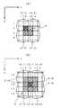
光通信エリア200は、詳述すると、光通信によるデータ通信サービスエリアを模式化したものであり、受信手段300の受信エリアおよび光出力手段700の送信エリアとで構成される。受信手段300は光通信エリア200内に存在する複数(図では便宜的に2個)の端末に接続された光通信装置からの光通信情報201、202(図では便宜的に輝点を模した図形で表している)をそれぞれ分離して受信する。受信手段300は好ましくは多数の画素(図では細かな桝目で表している)で構成された二次元画像センサであって、さらに、図示は略すが、光通信情報201、202を二次元画像センサの受光面に収束させた後、空間的に分離して受光するための撮影レンズや光通信情報201、202の波長域に対応した通過特性を持つ光学フィルターなどを備えている。受信手段300のハッチングを付けた画素301、302は各々光通信情報201、202の受信画素である。以下、画素301の座標値を(x301,y301)で表し、画素302の座標値を(x302,y302)で表すことにする。
【0008】
座標値(x301,y301)の受信情報(すなわち光通信情報201)と、座標値(x302,y302)の受信情報(すなわち光通信情報202)は、出力情報生成手段400および位置情報管理手段500に送られ、出力情報生成手段400で図外の情報ネットワークへ出力するためのネットワークパケットデータの生成が行なわれるとともに、位置情報管理手段500で各々の光通信情報201、202の物理位置情報の登録および物理位置情報と、情報ネットワーク上に設定される論理位置情報との関連付けが行われる。ここで、物理位置情報とは各々の光通信情報201、202の受信手段300における受信位置の情報であり、上記座標値(x301,y301)、(x302,y302)に相当する情報、またはこの座標値を表す情報である。
【0009】
したがって、上記の出力情報生成手段400でネットワークパケットデータを生成する際に、位置情報管理手段500から適切な論理位置情報を取得してその送信元アドレスにセットすることにより、光通信エリア200内に存在する複数の端末に接続された光通信装置の物理位置情報を、情報ネットワーク上の論理位置に変換してネットワークパケットデータを生成することができ、各端末の位置移動やリソース割り付けの変更に柔軟に対応することができる。
【0010】
また、座標値(x301,y301)の受信情報(すなわち光通信情報201)と、座標値(x302,y302)の受信情報(すなわち光通信情報202)は、上記のとおり、空間的に分離して受光されたものである。このため、受信手段300による受信動作は複数の光通信情報201、202について同時並行的に行われるから、少なくとも一つの光通信情報の受信動作によって他の光通信情報の受信が待たされることはなく、この点において情報伝達の輻輳を回避することができる。
【0011】
一方、情報ネットワークから出力されるネットワークパケットデータは、入力情報生成手段600で受信され、この入力情報生成手段600は、受信したネットワークパケットデータに設定された送信先アドレスで特定される論理位置情報を手掛かりに位置情報管理手段500を参照し、光通信情報201、202を送信出力した端末の適切な物理位置情報を取得し、その物理位置情報を同送信先アドレスに設定して光通信情報を生成する。光出力部600はこの光通信情報を光通信エリア200にブロード送信出力し、光通信エリア200内の各光通信装置は自分宛ての光通信情報を受信する。
【0012】
以上説明した本発明の技術思想に係る光通信中継装置100の各構成要素、すなわち、光通信エリア200、受信手段300、出力情報生成手段400、位置情報管理手段500、入力情報生成手段600および光出力手段700は、様々な実施の態様をとることができ、以下にその態様の一例を説明する。
【0013】
なお、以下の説明における様々な細部の特定ないし実例および数値や文字列その他の記号の例示は、本発明の思想を明瞭にするための、あくまでも参考であって、それらのすべてまたは一部によって本発明の思想が限定されない。また、周知の手法、周知の手順、周知のアーキテクチャおよび周知の回路構成等(以下「周知事項」)についてはその細部にわたる説明を避けるが、これも説明を簡潔にするためであって、これら周知事項のすべてまたは一部を意図的に排除するものではない。かかる周知事項は本発明の出願時点で当業者の知り得るところであるので、以下の説明に当然含まれている。
【0014】
図2は本実施の形態におけるネットワーク(情報ネットワーク)の全体構成図である。ネットワーク1は、ネットワーク媒体2、光通信エリア3、通信エリア外の端末群4およびサーバ群5などで構成されている。なお、“通信エリア外”とは光通信エリア3の外部に位置していることを意味する。ネットワーク媒体2は、イーサネット、ECHONET、IEEE1394、HomePNAなどの有線系またはBluetoothなどの無線系の通信媒体であり、汎用の通信プロトコル(例えばTCP/IP:Transmission Control Protocol/Internet Protocol)を用いて光通信エリア3、端末群4およびサーバ群5の間の情報伝達を媒介するものである。
【0015】
端末群4は、例えば、複数の端末4a〜4dで構成されており、各端末4a〜4dは、少なくとも当該ネットワーク1の中でユニークな固有の識別情報(アドレス)を有するとともに、サーバ群5によって提供される各種サービスまたは光通信エリア3の内部に存在する各種リソースを利用可能な所要のアプリケーションプログラムおよび上記プロトコルをサポートするネットワークOS(Operating System)を搭載している。
【0016】
サーバ群5は、リソース割り付けサーバ5aやその他のサーバ(例えば、メールサーバやファイルサーバ等)5b〜5dで構成されており、各サーバ5a〜5dは、端末群4と同様に少なくとも当該ネットワーク1の中でユニークな固有の識別情報(アドレス)を有するとともに、各サーバサービスを提供するためのアプリケーションプログラムおよび上記プロトコルをサポートするネットワークOSを搭載している。
【0017】
次に、光通信エリア3を説明するが、この光通信エリア3は、前述の光通信エリア200に相当し、事務室等の天井などに取り付けられた1台のブリッジコントローラ6(前述の光通信中継装置100に相当)を含み、そのブリッジコントローラ6から下向きに放射される末広がりのダウンリンク光DLによって、光通信エリア3の内部(所定のデータ通信サービスエリア内)に位置するn台の端末71〜7nへ一斉に情報を伝達するとともに、n台の端末71〜7nから上向きに放射される絞り込まれたビーム状のアップリンク光UL(発明の要旨に記載の光通信情報に相当)をブリッジコントローラ6で個別に受信(空間分離受信)し、各々のアップリンク光ULに含まれる情報を光通信エリア3内の他の端末またはネットワーク媒体2上の他の端末(端末群4を構成する)もしくはネットワーク媒体2上のサーバ(サーバ群5を構成するサーバ)などに伝達する。
【0018】
ブリッジコントローラ6は、所定の制御プログラムに従ってブリッジコントローラ6の全体動作(特に前述の出力情報生成手段400、位置情報管理手段500および入力情報生成手段600を実現するための動作)を制御するCPU10と、その制御プログラムなどを格納するプログラムメモリ11と、CPU10の主記憶として機能するワークメモリ12と、前述の汎用プロトコル(以下便宜的に「TCP/IP」とする)に従ってブリッジコートローラ6とネットワーク媒体2との間のデータ転送を実行するネットワークインターフェース(I/F)13と、CPU10からの送信情報に応じた駆動信号を生成する駆動部14と、その駆動信号に従ってダウンリンク光DLを発生する発光部15と、データ通信サービスエリア内の二次元画像を撮影してその画像信号を出力する受光部16(前述の光出力手段700に相当)と、受光部16から出力された画像信号を保持するフレームバッファメモリ17と、受光部16から出力された画像信号に含まれる各端末(発明の要旨に記載の光通信装置に相当)7i(iは1〜n)ごとの受信情報を保持するデータバッファメモリ18と、各端末7iごとの位置情報を保持する位置情報テーブルメモリ19とを備える。
【0019】
さらに、ブリッジコントローラ6の受光部16は、各端末7iからのアップリンク光ULを空間的に分離して撮像する撮影レンズ16aと、アップリンク光ULの波長域の通過特性を有する光学フィルター16bと、これらの光学素子(撮影レンズ16aおよび光学フィルター16b)を通過した、データ通信サービスエリア内の二次元平面像を画像信号に変換して所定周期ごとに出力する二次元画像センサ16cを含み、二次元画像センサ16cには、例えば、N×M画素(以下便宜的に「N=16、M=16」とする)構成のインターライン転送型CCD(Charge Coupled Device)が用いられている。受光部16は前述の受信手段300に相当する。
【0020】
データ通信サービスエリア内には、図示の例の場合、n台の端末7iが設けられている。各々の端末7iは、ビーム状所定波長域のアップリンク光ULに送信情報を乗せて発射する発光部20iと、ダウンリンク光DLを受光してそのダウンリンク光DLに含まれる受信情報を再生する受光部21iと、上記受信情報が自端末宛てである場合にその受信情報を所定のアプリケーションプログラムに渡し、また、必要に応じて所定のアプリケーションで上記送信情報を生成する端末本体部22iとを備える。
【0021】
次に、ブリッジコントローラ6を中心とした動作の概要について説明する。ブリッジコントローラ6は、大きく分けて、「位置情報管理処理機能」、「通信エリア内情報伝達処理機能」および「通信エリア内外情報伝達処理機能」の三つの機能を有する。
(1)位置情報管理処理機能
自通信エリア内に位置する各端末7iの物理位置と論理位置の対応関係を管理する機能である。物理位置とはその端末7iのデータ通信サービスエリア内の実際の位置であり、論理位置とはネットワーク上に展開されるアドレスのことである。各端末7iの物理位置と論理位置の対応関係情報は位置情報テーブルメモリ19に登録されており、この登録情報は受光部16から取り出される画像信号に基づいて逐次に更新されるようになっている。
(2)通信エリア内情報伝達機能
自通信エリア内の端末7i同士で行われる情報伝達を中継(ブリッジ)する機能である。
(3)通信エリア内外情報伝達機能
自通信エリア内の端末7iと、自通信エリア外の端末(端末群4やサーバ群5を構成するサーバ)との間で行われる情報伝達をブリッジする機能である。
【0022】
図3(a)はこれらの機能概念図である。光ネットワーク通信エリア26は自通信エリア(光通信エリア3)に相当し、イーサネットワーク通信エリア27は自通信エリア外に相当する。ブリッジコントローラ6は、これらの自通信エリア内と自通信エリア外の間に位置して、光入力部28a(受光部16に相当する。)、光出力部28b(発光部15に相当する。)、および、イーサネット入力部29a/出力部29b(イーサネットI/F13に相当する。)との間に複数の経路30a〜30dを形成し、これらの経路を使い分けながら、通信エリア内情報伝達機能および通信エリア内外情報伝達機能を実現する。例えば、通信エリア内情報伝達を行なう場合は経路30aを用い、通信エリア外情報伝達を行なう場合は経路30b(情報伝達方向が通信エリア外→通信エリア内の場合)または経路c(情報伝達方向が通信エリア内→通信エリア外の場合)を用いる。なお、経路dは通信エリア外からの情報伝達であってその情報が自通信エリア宛てでない場合に、その情報を破棄するために用いられる。
【0023】
経路30a〜30dの選択は、例えば、通信パケット内のアドレス情報に従って行なう。すなわち、図3(b)はアップリンク光ULやダウンリンク光DLに用いられるネットワークパケットデータPKTの構造図であり、OSI(Open System Interconnection)参照モデルのデータリンク層のパケット構造に対応するものである。PKTは、宛先アドレスのフレームFRM1、送り元アドレスのフレームFRM2および情報フレームFRM3などで構成されており、宛先アドレスと送り元アドレスは、例えば、MAC(Media Access Control)アドレスである。なお、パケットをフレームということもあるが、本明細書中では両者を区別しない。
【0024】
図4は端末(端末7i)、ブリッジコントローラ6、サーバ(リソース割り付けサーバ5a)およびその他のサーバ(メールサーバ等)の通信プロトコル構造図(Layer構成図)である。この図において端末(端末7i)の通信プロトコル31は、下位層から順に光通信処理層31a、IP層31bおよびTCP層31cを積み重ね、その上に同レベルのネットワークアプリケーション層31dとワークグループ等の自動設定アプリケーション層31eを重ねた構造を有している。また、ブリッジコントローラ6の通信プロトコル32は、最下位層に同一レベルの光通信処理層32aとイーサネット等の下位層32bを配置し、その上に順次、IP層32c、TCP層32dおよび端末位置応答サービス層32eを積み重ねた構造を有している。また、通信エリア外サーバ(リソース割り付けサーバ5a)の通信プロトコル33は、下位層から順にイーサネット等の下位層33a、IP層33b、TCP層33cおよびリソース割り付けサービス層33dを積み重ねた構造を有している。さらに、通信エリア外サーバ(メールサーバ等)の通信プロトコル34は、下位層から順にイーサネット等の下位層34a、IP層34b、TCP層34cおよびメールサーバ等34dを積み重ねた構造を有している。
【0025】
これらの各層とOSI参照モデルとの対応関係は、以下のとおりである。すなわち、OSI参照モデルは下位層から順に、ケーブルやコネクタの規格および信号電圧レベルなどを規定する「物理層」、一つのパケットの識別法を規定する「データリンク層」、ネットワークに接続するコンピュータ等の端末のアドレスを規定する「ネットワーク層」、誤り訂正手順やパケット抜けの確認手順およびパケット並びの復元手順などを規定する「トランスポート層」、通信の開始と終了の手順を規定する「セッション層」、データの表現形式などを規定する「プレゼンテーション層」、様々なネットワークサービスを提供する「アプリケーション層」の7階層で構成されている。図4の光通信処理層31a、32a、イーサネット等の下位層32b、33aおよび34aは上記OSI参照モデルの「物理層」と「データリンク層」に相当し、IP層31b、32c、33bおよび34bは同「ネットワーク層」に相当し、TCP層31c、32d、33cおよび34cは同「トランスポート層」に相当し、ネットワークアプリケーション層31d、ワークグループ自動設定アプリケーション層31e、端末位置応答サービス層32e、リソース割り付けサービス層33dおよびメールサーバ等34dは、同「セッション層」、同「プレゼンテーション層」および同「アプリケーション層」に相当する。
【0026】
既述のとおり、ブリッジコントローラ6は、「位置情報管理処理機能」、「通信エリア内情報伝達処理機能」および「通信エリア内外情報伝達処理機能」の三つの機能を有する。これらの機能を上記階層モデルを用いて説明すると、以下のとおりとなる。
【0027】
まず、図5は「位置情報管理処理機能」の概念図である。この図において、端末位置応答サービス32eは、端末位置情報要求元、例えば、図では、リソース割り付けサーバのリソース割り付けサービス33dからの要求に応答して、指定されたデータ通信エリア内の端末7iの位置情報を返送する。この要求は実線37で示すように、リソース割り付けサービス33d→TCP層33c→IP層33b→イーサネット等の下位層33a→イーサネット等の下位層32b→IP層32c→TCP層32d→端末位置応答サービス32eの経路で行われ、その応答は同一の経路を逆向きで行なわれる。また、その応答情報(端末位置情報)を使用した端末7iへのアクセスは、実線38で示すように、リソース割り付けサービス33d→TCP層33c→IP層33b→イーサネット等の下位層33a→イーサネット等の下位層32b→IP層32c→光通信処理層32a→光通信処理層31a→IP層31b→TCP層31c→ワークグループ自動設定アプリケーション層31eの経路で行われる。
【0028】
次に、図6は「通信エリア内情報伝達処理機能」の概念図である。この図において、ブリッジコントローラ6のIP層32cと光通信処理層32aは、任意の端末7i同士の情報伝達を仲介する。その経路は、実線36で示すように、ネットワークアプリケーション層31d→TCP層31c→IP層31b→光通信処理層31a→光通信処理層32a→IP層32c→光通信処理層31a→IP層31b→TCP層31c→ネットワークアプリケーション層31dである。
【0029】
次に、図7は「通信エリア内外情報伝達処理機能」の概念図である。この図において、ブリッジコントローラ6のIP層32c、光通信処理層32aおよびイーサネット等の下位層32bは、端末7iと通信エリア外に位置するサーバ(または端末)との間の情報伝達を仲介する。その経路は、実線35で示すように、ネットワークアプリケーション層31d→TCP層31c→IP層31b→光通信処理層31a→光通信処理層32a→IP層32c→イーサネット等の下位層32b→イーサネット等の下位層34a→IP層34b→TCP層34c→メールサーバ等34dである。
【0030】
次に、ブリッジコントローラ6における端末7iの位置情報管理の仕組みについて説明する。図8(a)はブリッジコントローラ6の受光部16から出力される画像信号の概念図である。図において、画像信号39は、二次元画像センサ16cの画素構成に対応した16×16個の画素配列を有しており、行方向をx座標、列方向をy座標で表し、各画素の座標値を(x,y)で表すことにすると、図示の画像信号39は、(0,0)から(15,15)までの256個の画素を有している。ここで、画像信号39の領域A、Bは、所定のスレッシュレベル以上の輝度値を有する領域であり、通信エリア内の任意の端末7iの発光部20iからのアップリンク光ULを表している。ブリッジコントローラ6は、この領域A、Bの代表画素の座標値を取り出して位置情報テーブルメモリ19に登録する。図8(b)は領域A、Bの位置情報を登録した位置情報テーブルメモリ19の概念図であり、現在(3,12)と(2,2)の二つの代表画素座標値が登録されている。テーブルへの登録は、画像信号39の画素スキャン順に行われる。例えば、(0,0)をスキャン開始点、(15,15)をスキャン終了点とすると、ラインスキャンの場合、最初に領域Aの代表画素座標値(2,2)を優先度1の行に登録し、次いで、領域Bの代表画素座標値(3,12)を登録するが、この領域Bの代表画素座標値(3,12)を登録する際に、領域Aの代表画素座標値(2,2)の登録行を優先度2の行に移動し、この移動によって空行となった優先度1の行に領域Bの代表画素座標値(3,12)を登録する。
【0031】
このように位置情報テーブルメモリ19には、所定のスレッシュレベル以上の輝度値を有する領域(図8では領域A、B)の物理位置情報(代表画素座標値)が登録されるが、さらに、位置情報テーブルメモリ19には、各々の物理位置情報(代表画素座標値)に関連付けられた論理位置情報(ネットワーク上のアドレス情報)も登録される。そして、このアドレスを参照することによって、ネットワーク上の論理位置を知ることができるようになっている。
【0032】
図9は領域A、Bの代表画素座標決定の概念図である。図示の例の場合、領域Aは(2,2)、(3,2)、(2,3)および(3,3)の4個の画素で構成されており、また、領域Bは(2,11)、(3,11)、(4,11)、(2,12)、(3,12)、(4,12)、(2,13)、(3,13)および(4,13)9個の画素で構成されている。4個の画素で構成されている場合は、スキャン順先頭の画素座標値(2,2)を代表画素座標値とし、また、9個の画素で構成されている場合は、スキャン順中央の画素座標値(3,12)を代表画素座標値とする。
【0033】
図10は位置情報テーブルメモリ19の更新概念図である。この図において、画像信号39は、領域B(図8の領域Bと同一のもの)と領域Cを有し、領域Aは消滅しているものとすると、この場合、新たに受信された領域Cの代表画素座標値(13,10)が位置情報テーブルメモリ19の先頭行(優先度1の行)に追加され、以降の登録順位が一つずつ下げられる。
【0034】
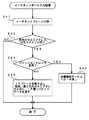
次に、ブリッジコントローラ6のCPU(発明の要旨に記載のパケットデータ送信手段、送信手段に相当)10で実行される制御プログラムの動作について説明する。図11は位置情報テーブルメモリ登録/更新処理のフローチャートである。このフローチャートを実行すると、まず、ステップS11で二次元画像センサ16cからの画像信号39をフレームバッファメモリ17にバッファリングする。そして、ステップS12でその画像信号39の各画素値を(0,0)、(0,1)、……、(n,n)の順にサーチし、ステップS13で所定のスレッシュレベル以上の画素値であるか否かを判定する。なお、(n,n)のnは二次元画像センサ16cのx座標の最大値とy座標の最大値である。
【0035】
いま、スレッシュレベル以上を判定しない場合は、ステップS14で再び画像信号39の各画素値を(0,0)、(0,1)、……、(n,n)の順にサーチし、ステップS15でサーチ完了か否かを判定し、完了であればフローチャートを終了する一方、完了でなければ、再びステップS13のスレッシュ判定を繰り返す。そして、スレッシュレベル以上の画素値を判定した場合は、ステップS16に進んで、該当画素を含む矩形領域のX,Y範囲(前記の領域A、BまたはCに相当)を求め、ステップS17でサンプリング点(前記の代表画素座標値に相当)を決定し、ステップS18で位置情報テーブルメモリ(発明の要旨に記載の情報保持手段に相当)19をサーチする。次に、ステップS19で現在のX,Y範囲に重なる位置情報が位置情報テーブルメモリ19に登録されているか否かを判定し、登録されていれば、ステップS24で該当エントリのサンプリング点の優先度を一つ上げた後、ステップS23で該当領域をゼロクリアして、ステップS14以降を実行する。
【0036】
一方、ステップS19で未登録を判定した場合は、ステップS20に進み、エントリフル(位置情報テーブルメモリ19のフル状態)であるか否かを判定する。そして、エントリフルであれば、ステップS21で優先度最小のエントリを削除し、ステップS22で各エントリを一つずつずらして先頭行(優先度1の行)に登録し、エントリフルでなければ、ステップS22で各エントリを一つずつずらして先頭行(優先度1の行)に登録した後、ステップS23で該当領域をゼロクリアして、ステップS14以降を実行する。
【0037】
したがって、このフローチャートによれば、光通信エリア3の内部に位置する各端末7iからの光通信情報(アップリンク光UL)を空間分離して受信し、その受信位置(二次元画像センサ16cの代表画素座標値)に対応する物理位置情報を位置情報テーブルメモリ19に登録するとともに、その物理位置情報に関連付けてネットワーク上の論理位置情報を登録することができる。
【0038】
図12はブリッジコントローラ6における光信号取り出し処理のフローチャートである。このフローチャートは位置情報テーブルメモリ19に登録されたサンプリング点の数だけ同時並行して行われる。このフローチャートを実行すると、まず、ステップS31でサンプリング点の監視を行ない、ステップS32で当該サンプリング点からの光通信情報の開始情報(例えば、スタートビット)を検出したか否かを判定する。そして、光通信情報の開始情報を検出しなければ、再びステップS31のサンプリング点の監視に戻る。
【0039】
光通信情報の開始情報を検出すると、ステップS33で光通信情報のデータフレーム(例えば、1バイトの非同期シリアルデータ)を取り出し、ステップS34でそのデータフレームをデータリンク層へ渡し、この動作をステップS35で光通信情報の終了情報(例えば、ストップビット)を検出するまで繰り返す。
【0040】
光通信情報の終了情報を検出すると、ステップS36で光通信情報中のアドレス情報(図3の宛先のMACアドレスと送り元のMACアドレス)を取り出し、宛先のMACアドレスを位置情報テーブルメモリ19に登録した後、ステップS37で宛先のMACアドレスおよび送り元のMACアドレスとともにIP層へネットワークパケットデータを渡して、フローチャートを終了する。
【0041】
既述のとおり、位置情報テーブルメモリ19は各端末7iごとの位置情報(論理位置と物理位置の情報)を保持する。論理位置情報は上記ステップS36で登録される宛先のMACアドレスと送り元のMACアドレスであり、一方の物理位置情報は位置情報テーブルメモリ19のサンプリング点である。例えば、位置情報テーブルメモリ19のあるサンプリング点(便宜的に「サンプリング点A」とする)で光通信情報を検出したとすると、その光通信情報に含まれる論理位置情報(宛先のMACアドレスと送り元のMACアドレス)はステップS36で位置情報テーブルメモリ19の特定メモリアドレス(サンプリング点Aのメモリアドレス)に登録されるが、このサンプリング点Aのメモリアドレスは光通信情報を生成出力した端末の物理位置情報になるから、自通信エリア内の各端末7iの物理位置情報と、光通信情報中のアドレス(論理位置情報)とを関連付けて位置情報テーブルメモリ19に保持することができ、以降、この位置情報テーブルメモリ19を参照することにより、論理位置情報から物理位置情報への変換またはその逆の変換(ブリッジ処理)を行なうことができる。
【0042】
したがって、このフローチャートによれば、光通信エリア3のの内部に位置する各端末7iからの光通信情報(アップリンク光UL)を同時並行的に受信して光通信エリア3の内外部へのブリッジ処理(論理位置情報←→物理位置情報)を行なうことができ、アップリンク光ULの受信輻輳を回避することができる。
【0043】
図13はイーサネットポート入力処理のフローチャートである。このフローチャートを実行すると、まず、ステップS41でイーサネットフレームを分解し、ステップS42で「宛先のMACアドレスは光通信エリア内?」を判定する。そして、光通信エリア内であれば、ステップS43で宛先がブリッジコントローラ6自体であるか否かを判定し、そうであれば、ステップS44で位置情報サービスにデータを渡してフローチャートを終了し、そうでなければ、ステップS45で、IPパケットを取り出し、宛先のMACアドレスおよび送り元のMACアドレスとともにIP層へネットワークパケットデータを渡してフローチャートを終了する。
【0044】
ステップS45において、宛先の端末7iの物理位置情報は、位置情報データメモリ19から取得する。例えば、先の光信号取り出し処理(図12参照)のステップS36において、位置情報データメモリ19のサンプリング点Aに対応したメモリアドレスにMACアドレスが登録されており、このMACアドレスが上記ステップS45における宛先のMACアドレスであるとすると、位置情報テーブルメモリ19からはサンプリング点Aに対応した位置情報が取り出されるので、この位置情報によって上記宛先のMACアドレスで明示された端末の物理位置を知ることができ、論理位置情報→物理位置情報のブリッジ処理を行なうことができる。
【0045】
したがって、このフローチャートによれば、光通信エリア3の外部からのネットワークパケットデータを光通信情報に変換して光通信エリア3の内部に光送信することができ、例えば、イーサネット等の有線系LANと光通信エリア3との間のインターフェースをとることができる。
【0046】
図14はデータ出力振り分け処理のフローチャートである。このフローチャートを実行すると、まず、ステップS51で「宛先のMACアドレスは通信エリア内向け?」を判定し、そうでなければ、ステップS52でイーサネットフレームを作成し、ステップS53でネットワークI/F13から出力してフローチャートを終了する。一方、宛先のMACアドレスが通信エリア内向けの場合には、ステップS54で宛先のMACアドレスが自分(ブリッジコントローラ6)向けであるか否かを判定し、自分向けであれば、ステップS55で位置情報サービスにデータを渡してフローチャートを終了し、そうでなければ、ステップS56で光通信用データリンクフレーム(パケットデータ)を作成し、ステップS57で調歩同期フレームを作成して駆動部14に出力してフローチャートを終了する。
【0047】
したがって、このフローチャートによれば、光通信エリア3の外部への情報伝送を行なうことができるとともに、光通信エリア3から同光通信エリア3への折り返し的な情報伝送も行なうことができ、例えば、イーサネット等の有線系LANと光通信エリア3との間のインターフェースをとることができるほか、光通信エリア3単独の利用形態も取ることができる。
【0048】
図15はリソース自動割り付け処理のタイムランを示す図である。この図において、端末7iからリソース要求があった場合、ブリッジコントローラ6はその要求をブリッジしてリソース割り付けサーバ4aに伝える。リソース割り付けサーバ4aは、その要求に応答して、ブリッジコントローラ6に要求元の端末7iの座標問い合わせを行なう。ブリッジコントローラ6は、位置情報テーブルメモリ19を検索して該当する座標情報をリソース割り付けサーバ4aに応答する。リソース割り付けサーバ4aは、その座標情報に基づいて割り付けリソースを決定するとともに、その決定した割り付けリソースをブリッジコントローラ6を経由して端末7iに応答し、端末7iは割り付けリソースをレジストリに登録して更新する。
【0049】
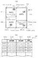
図16(a)はリソース自動割り付け処理の概念図である。図において、ブリッジコントローラ6のデータ通信サービスエリア50には、複数のリソースRS_1〜RS_4が配置されているものとする。今、例えば、データ通信サービスエリア50を事務所と仮定し、リソースRS_1〜RS_4をプリンタと仮定すると、これらのリソースRS_1〜RS_4を近くに位置する端末7i(不図示)に割り当てるようにすれば、遠くのプリンタに出力用紙を取りに行かなくて済むので好都合である。図に示すように、データ通信サービスエリア50を、リソースRS_1〜RS_4ごとに区分け51〜54して各々をエリア1〜エリア4と呼ぶことにすると、エリア1〜エリア4の各々に位置する端末7i(不図示)について、自エリア内のリソースを割り当てるようにすればよい。図16(b)はそのような考え方に従って割り当てられたリソース割り付けテーブルの概念図であり、このテーブルはリソース割り付けサーバ4aが管理するものである。図16(b)において、55aはエリア表示欄、55bはエリアの始点座標欄、55cはエリアの終点座標欄、55dはそのエリアに割り付けられたリソース名欄である。例えば、エリア1は(x1s,y1s)から(x1e,y1e)までの矩形エリアであり、このエリアにはリソースRS_1が割り付けられている。今、任意の端末7iが、例えば、エリア1に位置していた場合を想定すると、その端末7iの物理位置は(x1s,y1s)から(x1e,y1e)の範囲に含まれるから、リソース割り付けサーバ4aは、リソース割り付けテーブルを参照してエリア1のリソースRS_1をその端末7iに割り付ける。したがって、端末7iから最も近い位置のプリンタ(リソースRS_1)を使用することができる。
【0050】
【発明の効果】
本発明によれば、所定の光通信エリア内に存在する光通信装置からの光通信情報を空間分離して同時並行的に受光でき、且つ、その受光位置の情報を当該光通信装置の物理位置情報として管理することができる。したがって、上記の同時並行的な受光動作によって光通信装置からの光通信情報受信の輻輳を回避でき、さらに、上記の物理位置情報の管理によってネットワーク上の論理情報との対応づけを行なうことができるようになる。その結果、光通信エリア内の情報伝達の輻輳を招くことなく、しかも、各端末の位置移動やリソース割り付けの変更に柔軟に対応できる光通信中継装置を提供することができる。
【図面の簡単な説明】
【図1】本実施の形態における光通信中継装置の概念構成図である。
【図2】本実施の形態におけるネットワークの全体構成図である。
【図3】ブリッジコントローラの機能概念図およびパケット構成図である。
【図4】通信プロトコル構造図である。
【図5】位置情報管理処理機能の概念図である。
【図6】通信エリア内情報伝達処理機能の概念図である。
【図7】通信エリア内外情報伝達処理機能の概念図である。
【図8】ブリッジコントローラの受光部から出力される画像信号の概念図および位置情報テーブルメモリの登録情報概念図である。
【図9】領域A、Bの代表画素座標決定の概念図である。
【図10】位置情報テーブルメモリ19の更新概念図である。
【図11】位置情報テーブルメモリ登録/更新処理のフローチャートである。
【図12】ブリッジコントローラにおける光信号取り出し処理のフローチャートである。
【図13】イーサネットポート入力処理のフローチャートである。
【図14】データ出力振り分け処理のフローチャートである。
【図15】リソース自動割り付け処理のタイムランを示す図である。
【図16】リソース自動割り付け処理の概念図およびリソース割り付けテーブルの概念図である。
【符号の説明】
UL アップリンク光(光通信情報)
3 光通信エリア
7i 端末(光通信装置)
10 CPU(パケットデータ送信手段、送信手段)
19 位置情報データメモリ(情報保持手段)
100 光通信中継装置
200 光通信エリア
300 受信手段
400 出力情報生成手段(パケットデータ送信手段)
500 位置情報管理手段(情報保持手段)
600 入力情報生成手段(送信手段)[0001]
BACKGROUND OF THE INVENTION
The present invention relates to an optical communication repeater, and in particular, grasps the physical position of a terminal that executes optical communication processing existing in a predetermined optical communication area, and associates logical position information on the network with the physical position information. The present invention relates to an optical communication repeater that facilitates movement of the terminal, resource allocation, and the like.
[0002]
[Prior art]
Conventionally, in places where cable laying is difficult, such as factories and event venues, wireless LANs (Local Area Networks) using infrared rays or the like are sometimes constructed. According to this, the optical communication relay device is attached to the ceiling or the like, the optical communication device is connected to each terminal, and the optical communication device is located in the optical communication area (data communication service area of the optical communication relay device). Thus, wireless infrared communication can be performed between each optical communication device and the optical communication relay device, and various servers and resources connected to a wired LAN such as Ethernet are accessed via the optical communication relay device. be able to.
[0003]
[Problems to be solved by the invention]
However, since the conventional optical communication repeater described above performs time-division communication with a plurality of terminals in the optical communication area, it is likely to cause congestion of information transmission in the optical communication area. There was a problem. In addition, since the plurality of terminals in the optical communication area are identified based on the logical position information on the network, there is a problem that it is not possible to flexibly cope with the movement of the position of each terminal and the change of resource allocation.
[0004]
Therefore, the problem to be solved by the present invention is to provide an optical communication repeater that does not cause congestion of information transmission in the optical communication area and can flexibly cope with the movement of the position of each terminal and the change of resource allocation. There is.
[0005]
[Means for Solving the Problems]
The present invention provides a plurality of pieces of optical communication information from an optical communication apparatus existing in a predetermined optical communication area.Each of these is separated into pixel units of the two-dimensional image sensor using a two-dimensional image sensor and received. DoLight reception Means,
SaidLight reception By meansThe pixel coordinates of the two-dimensional image sensor when receiving the optical communication information are used as physical position information of the optical communication information. Information holding means for storing and holding the physical position information in association with the logical position information set on the information network;
SaidLight reception By meansLight reception Optical communication informationIs transmitted from the information holding means to the transmission source address of the optical communication information, and the logical position information corresponding to the physical position information of the optical communication information is extracted from the information holding means. Packet data transmission means for generating and transmitting network packet data to be transmitted to the information network;
Physical location information corresponding to the logical location information indicated by the destination address of the network packet data from the information network Take out from the information holding meansAnd set it to the destination address of the network packet data Transmitting means for transmitting within the optical communication area;
The It is characterized by having.
[0006]
DETAILED DESCRIPTION OF THE INVENTION
Hereinafter, embodiments of the present invention will be described in detail with reference to the drawings.
First, the conceptual configuration of the optical communication repeater in the present embodiment will be described. FIG. 1 is a conceptual configuration diagram of an optical communication repeater in this embodiment. In this figure, the optical communication repeater 100 has an optical communication area.(In the figure, this is called the optical segment) 200, receiving means(Equivalent to the light receiving means described in the gist of the invention) 300, output information generating means (corresponding to the packet data transmitting means described in the gist of the invention) 400, position information managing means (corresponding to information holding means described in the gist of the invention) 500, input information generating means (corresponding to the gist of the invention) (Corresponding to the transmitting means described) 600 and an optical output means 700.
[0007]
More specifically, the optical communication area 200 is a schematic diagram of a data communication service area by optical communication, and includes a reception area of the reception unit 300 and a transmission area of the
[0008]
Coordinate value (x301 , Y301 ) Reception information (that is, optical communication information 201) and coordinate values (x302 , Y302 ) Received information (that is, optical communication information 202) is sent to the output information generation means 400 and the position information management means 500, and the output information generation means 400 generates network packet data for output to an information network outside the figure. At the same time, the position information management means 500 registers the physical position information of each of the
[0009]
Therefore, when the network information is generated by the output
[0010]
Also, the coordinate value (x301 , Y301 ) Reception information (that is, optical communication information 201) and coordinate values (x302 , Y302 ) Received information (that is, optical communication information 202) is received spatially separated as described above. For this reason, the receiving operation by the receiving unit 300 is performed in parallel for a plurality of
[0011]
On the other hand, the network packet data output from the information network is received by the input
[0012]
Each component of the optical communication repeater 100 according to the technical idea of the present invention described above, that is, the optical communication area 200, the receiving means 300, the output information generating means 400, the position information managing means 500, the input information generating means 600, and the light The
[0013]
It should be noted that the specification or examples of various details and the illustrations of numerical values, character strings, and other symbols in the following description are only for reference in order to clarify the idea of the present invention, and all or part of them may The idea of the invention is not limited. In addition, a well-known method, a well-known procedure, a well-known architecture, a well-known circuit configuration, and the like (hereinafter, “well-known matter”) are not described in detail, but this is also to simplify the description. Not all or part of the matter is intentionally excluded. Such well-known matters are known to those skilled in the art at the time of filing of the present invention, and are naturally included in the following description.
[0014]
FIG. 2 is an overall configuration diagram of a network (information network) in the present embodiment. The
[0015]
The
[0016]
The
[0017]
Next, the
[0018]
The
[0019]
Further, the
[0020]
In the data communication service area, in the illustrated example,
[0021]
Next, an outline of the operation centering on the
(1) Location information management processing function
Each
(2) Information transmission function within the communication area
Terminal 7 in its own communication areai This is a function that relays (bridges) information transmission between each other.
(3) Communication area inside / outside information transmission function
Terminal 7 in its own communication areai And a function of bridging information transmission performed between terminals outside the own communication area (servers constituting the
[0022]
FIG. 3A is a conceptual diagram of these functions. The optical
[0023]
The selection of the
[0024]
FIG. 4 shows a terminal (terminal 7i ), A communication protocol structure diagram (Layer configuration diagram) of the
[0025]
The correspondence between each of these layers and the OSI reference model is as follows. That is, the OSI reference model is, in order from the lower layer, a “physical layer” that defines cable and connector standards and signal voltage levels, a “data link layer” that defines a method for identifying one packet, a computer connected to a network, etc. "Network layer" that prescribes the address of the terminal, "Transport layer" that prescribes error correction procedures, packet drop confirmation procedures, and packet order restoration procedures, and "session layer" that prescribes the start and end procedures of communication ”, A“ presentation layer ”that defines a data expression format, and an“ application layer ”that provides various network services. The optical communication processing layers 31a and 32a and
[0026]
As described above, the
[0027]
First, FIG. 5 is a conceptual diagram of the “location information management processing function”. In this figure, the terminal location response service 32e is a terminal location information request source, for example, in the figure, in response to a request from the
[0028]
Next, FIG. 6 is a conceptual diagram of the “communication area information transmission processing function”. In this figure, the
[0029]
Next, FIG. 7 is a conceptual diagram of the “communication area inside / outside information transmission processing function”. In this figure, the
[0030]
Next, the
[0031]
As described above, physical position information (representative pixel coordinate values) of areas (areas A and B in FIG. 8) having a luminance value equal to or higher than a predetermined threshold level is registered in the position
[0032]
FIG. 9 is a conceptual diagram of determining the representative pixel coordinates of the regions A and B. In the illustrated example, the area A is composed of four pixels (2, 2), (3, 2), (2, 3) and (3, 3), and the area B is (2 , 11), (3,11), (4,11), (2,12), (3,12), (4,12), (2,13), (3,13) and (4,13) ) It is composed of 9 pixels. If it is composed of 4 pixels, the pixel coordinate value (2, 2) at the head of the scan order is the representative pixel coordinate value, and if it is composed of 9 pixels, the center pixel in the scan order The coordinate value (3, 12) is set as the representative pixel coordinate value.
[0033]
FIG. 10 is an update conceptual diagram of the position
[0034]
Next, the operation of a control program executed by the CPU (corresponding to the packet data transmission means and transmission means described in the gist of the invention) 10 of the
[0035]
If it is determined that the threshold level is not exceeded, the pixel values of the
[0036]
On the other hand, if unregistered is determined in step S19, the process proceeds to step S20 to determine whether the entry is full (the position
[0037]
Therefore, according to this flowchart, each terminal 7 located inside the
[0038]
FIG. 12 is a flowchart of the optical signal extraction process in the
[0039]
When the start information of the optical communication information is detected, a data frame (for example, 1-byte asynchronous serial data) of the optical communication information is extracted in step S33, and the data frame is passed to the data link layer in step S34, and this operation is performed in step S35. Until the end information (for example, stop bit) of the optical communication information is detected.
[0040]
When the end information of the optical communication information is detected, the address information (the destination MAC address and the source MAC address in FIG. 3) in the optical communication information is extracted in step S 36 and the destination MAC address is registered in the position
[0041]
As described above, the location
[0042]
Therefore, according to this flowchart, each terminal 7 located inside the
[0043]
FIG. 13 is a flowchart of the Ethernet port input process. When this flowchart is executed, first, the Ethernet frame is disassembled in step S41, and it is determined in step S42 whether the destination MAC address is within the optical communication area? If it is within the optical communication area, it is determined in step S43 whether or not the destination is the
[0044]
In step S45, the physical position information of the destination terminal 7i is acquired from the position
[0045]
Therefore, according to this flowchart, network packet data from the outside of the
[0046]
FIG. 14 is a flowchart of the data output distribution process. When this flowchart is executed, first, in step S51, it is determined whether the destination MAC address is within the communication area? If not, an Ethernet frame is created in step S52, and output from the network I /
[0047]
Therefore, according to this flowchart, it is possible to perform information transmission to the outside of the
[0048]
FIG. 15 is a diagram showing a time run of automatic resource allocation processing. In this figure, the
[0049]
FIG. 16A is a conceptual diagram of automatic resource allocation processing. In the figure, it is assumed that a plurality of resources RS_1 to RS_4 are arranged in the data communication service area 50 of the
[0050]
【The invention's effect】
According to the present invention, optical communication information from an optical communication device existing in a predetermined optical communication area is spatially separated and simultaneously processed in parallel.Light reception And thatLight reception The position information can be managed as physical position information of the optical communication apparatus. Therefore, the above concurrentLight reception By actionOptical communication information from optical communication equipment Reception congestion can be avoided, and further, correspondence with logical information on the network can be performed by managing the physical position information. As a result, it is possible to provide an optical communication repeater that does not cause congestion of information transmission in the optical communication area and can flexibly cope with the movement of the location of each terminal and the change of resource allocation.
[Brief description of the drawings]
FIG. 1 is a conceptual configuration diagram of an optical communication repeater in the present embodiment.
FIG. 2 is an overall configuration diagram of a network in the present embodiment.
FIG. 3 is a functional conceptual diagram and a packet configuration diagram of a bridge controller.
FIG. 4 is a communication protocol structure diagram;
FIG. 5 is a conceptual diagram of a location information management processing function.
FIG. 6 is a conceptual diagram of an information transmission processing function within a communication area.
FIG. 7 is a conceptual diagram of a communication area inside / outside information transmission processing function.
FIG. 8 is a conceptual diagram of an image signal output from a light receiving unit of a bridge controller and a registered information conceptual diagram of a position information table memory.
FIG. 9 is a conceptual diagram of determining representative pixel coordinates of regions A and B.
FIG. 10 is a conceptual diagram of updating the position
FIG. 11 is a flowchart of a location information table memory registration / update process.
FIG. 12 is a flowchart of an optical signal extraction process in the bridge controller.
FIG. 13 is a flowchart of Ethernet port input processing.
FIG. 14 is a flowchart of data output distribution processing.
FIG. 15 is a diagram showing a time run of automatic resource allocation processing.
FIG. 16 is a conceptual diagram of automatic resource allocation processing and a conceptual diagram of a resource allocation table.
[Explanation of symbols]
UL uplink light (optical communication information)
3 Optical communication area
7i Terminal (optical communication device)
10 CPU (packet data transmission means, transmission means)
19 Position information data memory (information holding means)
100 Optical communication repeater
200 Optical communication area
300 Receiving means
400 Output information generation means (packet data transmission means)
500 Location information management means (information holding means)
600 Input information generation means (transmission means)
Claims (1)
Translated fromJapanese前記受光手段によって前記光通信情報を受光したときの前記二次元画像センサの画素座標を当該光通信情報の物理位置情報とすると共に該物理位置情報と情報ネットワーク上に設定される論理位置情報とを関連付けて記憶保持する情報保持手段と、
前記受光手段によって受光された光通信情報を前記情報ネットワーク上に送信する際に該光通信情報の物理位置情報に対応する論理位置情報を前記情報保持手段から取り出して該光通信情報の送信元アドレスにセットして前記情報ネットワークに送信すべきネットワークパケットデータを生成し、送信するパケットデータ送信手段と、
前記情報ネットワークからのネットワークパケットデータの送信先アドレスで示された論理位置情報に対応する物理位置情報を前記情報保持手段から取り出して該ネットワークパケットデータの送信先アドレスにセットして前記光通信エリア内に送信する送信手段と、
を備えたことを特徴とする光通信中継装置。Alight receiving meansfor separating and receiving each of a plurality of optical communication information from an optical communication device existing in a predetermined optical communication area inunits of pixels of the two-dimensional image sensor using a two-dimensional image sensor ;
The pixel coordinates of the two-dimensional image sensor when the optical communication information is received by thelight receiving means are used asthe physical position information of the optical communication information, and the physical position information and logical position information set on the information network are used. Information holding means for storing and holding in association;
When transmitting the optical communication informationreceived by thelightreceiving meanson the information network, the logical position information corresponding to the physical position information of the optical communication information is extracted from the information holding means and the source address of the optical communication information Packet data transmission means for generating and transmitting network packet data to be transmitted to the information networkby setting to
It saidsetscorresponding physical location in the logical position information indicated by the destination address of the network packetdata Eject from said information holding meansto a destination address of the network packet datafrom said information network optical communication A transmission means for transmitting within the area;
Optical communication relay apparatus characterized by comprisinga.
Priority Applications (1)
| Application Number | Priority Date | Filing Date | Title |
|---|---|---|---|
| JP2000056545AJP3799593B2 (en) | 2000-03-01 | 2000-03-01 | Optical communication repeater |
Applications Claiming Priority (1)
| Application Number | Priority Date | Filing Date | Title |
|---|---|---|---|
| JP2000056545AJP3799593B2 (en) | 2000-03-01 | 2000-03-01 | Optical communication repeater |
Publications (2)
| Publication Number | Publication Date |
|---|---|
| JP2001244948A JP2001244948A (en) | 2001-09-07 |
| JP3799593B2true JP3799593B2 (en) | 2006-07-19 |
Family
ID=18577471
Family Applications (1)
| Application Number | Title | Priority Date | Filing Date |
|---|---|---|---|
| JP2000056545AExpired - LifetimeJP3799593B2 (en) | 2000-03-01 | 2000-03-01 | Optical communication repeater |
Country Status (1)
| Country | Link |
|---|---|
| JP (1) | JP3799593B2 (en) |
Families Citing this family (8)
| Publication number | Priority date | Publication date | Assignee | Title |
|---|---|---|---|---|
| JP3918813B2 (en) | 2001-10-23 | 2007-05-23 | ソニー株式会社 | Data communication system, data transmission device, and data reception device |
| JP4689412B2 (en)* | 2005-08-31 | 2011-05-25 | 京セラ株式会社 | Transmitting apparatus and communication system |
| JP4600297B2 (en)* | 2006-01-11 | 2010-12-15 | ソニー株式会社 | Object related information recording system, object related information recording method, television receiver and display control method |
| JP4487211B2 (en) | 2007-06-01 | 2010-06-23 | カシオ計算機株式会社 | Connection control apparatus and network connection control program |
| JP4552074B2 (en)* | 2008-05-29 | 2010-09-29 | カシオ計算機株式会社 | Information transmission system, information decoding apparatus, notification method, and program |
| JP5126896B2 (en)* | 2009-02-13 | 2013-01-23 | シャープ株式会社 | Electronic device, communication area setting method, and program |
| CN110278028B (en)* | 2019-06-20 | 2021-01-12 | Oppo广东移动通信有限公司 | Information transmission method and related product |
| WO2024018920A1 (en)* | 2022-07-21 | 2024-01-25 | ソニーセミコンダクタソリューションズ株式会社 | Information processing device and information processing method |
- 2000
- 2000-03-01JPJP2000056545Apatent/JP3799593B2/ennot_activeExpired - Lifetime
Also Published As
| Publication number | Publication date |
|---|---|
| JP2001244948A (en) | 2001-09-07 |
Similar Documents
| Publication | Publication Date | Title |
|---|---|---|
| CN101421999B (en) | Network equipment and network equipment management method | |
| JP4537357B2 (en) | Dynamic construction of VLAN interface based on subscriber information string | |
| US7548540B2 (en) | Dynamic discovery of ISO layer-2 topology | |
| US9281995B2 (en) | Virtual network and management method of virtual network | |
| JP2770782B2 (en) | LAN connection device | |
| JP3478770B2 (en) | How to classify network devices | |
| WO2013062208A1 (en) | Image forming apparatus supporting plurality of network interfaces and method of editing routing table thereof | |
| JP2004515967A (en) | System for automatically identifying the physical location of network end devices | |
| JP4648251B2 (en) | Network relay system, network relay system control method, and management device in network relay system | |
| JP3799593B2 (en) | Optical communication repeater | |
| JP4381642B2 (en) | Routing control method and apparatus in mixed environment of hierarchical network and non-hierarchical network | |
| CN101729404A (en) | Mechanism for enabling layer two host addresses to be shielded from the switches in a network | |
| KR101860486B1 (en) | Image forming system having image forming apparatus for supporting a plurality of network interfaces and method for editing routing table thereof | |
| US7970282B2 (en) | Network repeater, repeater controlling method and program product | |
| JP4193832B2 (en) | Network system and data transfer method | |
| JP6216466B2 (en) | Domain control method and domain control apparatus | |
| JP5911620B2 (en) | Virtual network management server and edge router | |
| JP2023016993A5 (en) | ||
| CN104184916A (en) | Image forming apparatus and image forming | |
| JP4527650B2 (en) | Physical wiring control device, physical wiring control method, and physical wiring control program | |
| JP4282571B2 (en) | Facsimile machine | |
| JP2004135108A (en) | Communication control method, communication terminal, router, communication terminal control program, and router control program | |
| CN101072159A (en) | System and apparatus for managing internal virtual local area network | |
| JP3675806B2 (en) | Address assignment method and apparatus in communication network | |
| JPH10257085A (en) | Data communication system device, connection terminal device and server device |
Legal Events
| Date | Code | Title | Description |
|---|---|---|---|
| A621 | Written request for application examination | Free format text:JAPANESE INTERMEDIATE CODE: A621 Effective date:20040409 | |
| A977 | Report on retrieval | Free format text:JAPANESE INTERMEDIATE CODE: A971007 Effective date:20060113 | |
| A131 | Notification of reasons for refusal | Free format text:JAPANESE INTERMEDIATE CODE: A131 Effective date:20060117 | |
| A521 | Written amendment | Free format text:JAPANESE INTERMEDIATE CODE: A523 Effective date:20060317 | |
| TRDD | Decision of grant or rejection written | ||
| A01 | Written decision to grant a patent or to grant a registration (utility model) | Free format text:JAPANESE INTERMEDIATE CODE: A01 Effective date:20060403 | |
| A61 | First payment of annual fees (during grant procedure) | Free format text:JAPANESE INTERMEDIATE CODE: A61 Effective date:20060416 | |
| R150 | Certificate of patent or registration of utility model | Free format text:JAPANESE INTERMEDIATE CODE: R150 Ref document number:3799593 Country of ref document:JP Free format text:JAPANESE INTERMEDIATE CODE: R150 | |
| FPAY | Renewal fee payment (event date is renewal date of database) | Free format text:PAYMENT UNTIL: 20090512 Year of fee payment:3 | |
| FPAY | Renewal fee payment (event date is renewal date of database) | Free format text:PAYMENT UNTIL: 20100512 Year of fee payment:4 | |
| FPAY | Renewal fee payment (event date is renewal date of database) | Free format text:PAYMENT UNTIL: 20110512 Year of fee payment:5 | |
| FPAY | Renewal fee payment (event date is renewal date of database) | Free format text:PAYMENT UNTIL: 20110512 Year of fee payment:5 | |
| FPAY | Renewal fee payment (event date is renewal date of database) | Free format text:PAYMENT UNTIL: 20120512 Year of fee payment:6 | |
| FPAY | Renewal fee payment (event date is renewal date of database) | Free format text:PAYMENT UNTIL: 20120512 Year of fee payment:6 | |
| FPAY | Renewal fee payment (event date is renewal date of database) | Free format text:PAYMENT UNTIL: 20130512 Year of fee payment:7 | |
| FPAY | Renewal fee payment (event date is renewal date of database) | Free format text:PAYMENT UNTIL: 20130512 Year of fee payment:7 | |
| EXPY | Cancellation because of completion of term |