JP3798996B2 - Vehicle accident situation automatic collection system - Google Patents
Vehicle accident situation automatic collection systemDownload PDFInfo
- Publication number
- JP3798996B2 JP3798996B2JP2002178901AJP2002178901AJP3798996B2JP 3798996 B2JP3798996 B2JP 3798996B2JP 2002178901 AJP2002178901 AJP 2002178901AJP 2002178901 AJP2002178901 AJP 2002178901AJP 3798996 B2JP3798996 B2JP 3798996B2
- Authority
- JP
- Japan
- Prior art keywords
- vehicle
- accident
- video
- impact
- data
- Prior art date
- Legal status (The legal status is an assumption and is not a legal conclusion. Google has not performed a legal analysis and makes no representation as to the accuracy of the status listed.)
- Expired - Lifetime
Links
- 238000001514detection methodMethods0.000claimsdescription58
- 238000010586diagramMethods0.000claimsdescription44
- 238000004891communicationMethods0.000claimsdescription15
- 239000012778molding materialSubstances0.000claimsdescription2
- 230000003213activating effectEffects0.000claims1
- 206010039203Road traffic accidentDiseases0.000description7
- 230000005540biological transmissionEffects0.000description6
- 238000000034methodMethods0.000description3
- 238000012545processingMethods0.000description3
- 101150012579ADSL geneProteins0.000description1
- 102100020775Adenylosuccinate lyaseHuman genes0.000description1
- 108700040193Adenylosuccinate lyasesProteins0.000description1
- 238000012935AveragingMethods0.000description1
- XAGFODPZIPBFFR-UHFFFAOYSA-NaluminiumChemical compound[Al]XAGFODPZIPBFFR-UHFFFAOYSA-N0.000description1
- 229910052782aluminiumInorganic materials0.000description1
- 230000010485copingEffects0.000description1
- 230000000694effectsEffects0.000description1
- 239000000463materialSubstances0.000description1
- 239000000758substrateSubstances0.000description1
- 230000001360synchronised effectEffects0.000description1
- 238000012795verificationMethods0.000description1
Images


Landscapes
- Time Recorders, Dirve Recorders, Access Control (AREA)
- Closed-Circuit Television Systems (AREA)
- Traffic Control Systems (AREA)
- Mobile Radio Communication Systems (AREA)
- Navigation (AREA)
- Television Signal Processing For Recording (AREA)
- Management, Administration, Business Operations System, And Electronic Commerce (AREA)
- Financial Or Insurance-Related Operations Such As Payment And Settlement (AREA)
Description
Translated fromJapanese【0001】
【発明の属する技術分野】
本発明は、車輌の外部の映像を逐次撮影して保存し、これを保険会社のサイトに送信する車輌事故状況自動収集システムに関する。
【0002】
【従来の技術】
車輌の交通事故発生時の直前、直後の映像を記録して、事故発生時の状況を把握できるようにした装置がある。
【0003】
例えば、特開平9−39739号公報の車載型事故映像及び音声記録装置は、図15に示すように、監視カメラ及びマイク1を映像伝送ケーブル8で記憶装置2に接続し、この記憶装置2とデータケーブル9で記録開始及び停止装置3に接続している。また、電源ケーブル10で電源装置4と接続している。
【0004】
すなわち、車輌の内部又は外部に監視カメラ及びマイク1を設置して、接近してくる車輌の映像、音声を取得させ、これお記憶装置2に記録する。
【0005】
そして、交通事故発生時には、記憶装置2を取り外して、事故の直前、直後の事故発生時の状況を把握できるようにしていた。
【0006】
一方、事故が発生した場合は、自動車保険契約者が電話で「事故受付サービス」へ連絡し、後日、保険会社の事故受付表に発生時の状況を詳細に記述していた。
【0007】
【発明が解決しようとする課題】
しかしながら、従来の上記の特開平9−39739号公報の車載型事故映像及び音声記録装置は、記憶装置に映像、音声を登録するだけであるから、記憶装置の記録データを解析して状況が分かることになる。
【0008】
すなわち、記録データの解析のための作業が発生し、結果としてコストがかかるという課題があった。
【0009】
また、保険会社は自動車事故の保険金の支払いは、ドライバが作成した事故受付表が届いてから、内容をチェックして必要な書類を作成して支払うことになる。このとき、上記のような従来の装置を用いていた場合は、記録データを保険会社が解析して、事故受付表の内容が記録データの内容と相違ないことを確認することになる。
【0010】
従って、保険会社では、記録データの内容を解析して画像化する人と、この画像と事故受付表の内容とを比較チェックする人が必要になるので、コストと時間がかかるという課題があった。
【0011】
さらに、車輌事故があったときは、ドライバーは電話連絡で関係機関に通報することになるが、事故の発生直後はパニック状態にあるのがほとんどであり、相手に正確な状況を伝えることができないのがほとんどであり、例えば保険会社側で通報を受けても直ぐに対処の方法、保険手続きの方法を確定させることができないという課題があった。
【0012】
また、ドライバにとっても、事故受付表を作成したときは既に時間が経過しているので、正確に状況を事故受付表に反映させることができないという課題があった。
【0013】
本発明は以上の課題を解決するためになされたもので、車輌事故時の状況を直ちに保険会社のサイトが得ることができると共に、事故時に必要な書類をドライバによらないで自動作成できる車輌事故状況自動収集システムを得ることを目的とする。
【0014】
【課題を解決するための手段】
本発明は、自車輌に設けられた端末が車輌外の映像を撮影させて蓄積し、該蓄積した映像の内で衝突時付近の映像部分を含んだ映像付き情報を通信網を介して事故受付サイトのサーバに収集させて、前記映像付きの事故状況受付表をプリンタから出力させる車輌事故状況自動収集システムである。
【0015】
前記自車輌に設けられた端末は、
前記車輌内から車輌の外を撮影可能に設けられ、この車輌の外を撮影した映像データを出力するCCDカメラと、
円形状であり、車輌内の中央部に固定され、車輌の前方中央を0度方向として、この0度方向の位置から10度間隔に衝撃度検知センサを水平周囲360度に渡って設け、これらの検知データを出力する衝撃度検知センサ部と、
地図上の自車輌の緯度、経度及び年月日、時刻を含むGPSデータを出力するGPS機能付きカーナビと、
これらに、それぞれのケーブルで接続したボックスと
を車輌内に備えてなる。
前記ボックスは、コンピュータ、キーボード及び表示器を備え、
前記キーボードからの車番、証券番号、氏名、携帯電話番号を含む顧客情報が記憶されたメモリと、
フラッシュメモリと、コンピュータと、ビデオキャプチャーと、前記事故受付サイトのサーバと通信をする通信ICとを備えて、これらを筐体内に非加熱モールド材でモールドされており、
前記コンピュータは、
前記CCDカメラを動作させて前記映像データを定期的に得ると共に、前記通信ICを動作させて前記事故受付サイトのサーバと回線を確立させる手段と、
一定時間毎に、前記CCDカメラからの映像データを前記ビデオキャプチャーで取り込み、前記GPSデータと前記衝撃度検知センサからの検知データと共に前記フラッシュメモリに順次保存する手段と、
前記衝撃度検知センサの検知データを、離散化平均して衝撃度を求め、最もピークが集中している範囲を衝撃方向として求め、これらを含む衝撃度・方向検知データを生成して前記フラッシュメモリに保存する手段と、
前記一定時間毎に前記衝撃度検知センサ部からの衝撃度・検知データが前記フラッシュメモリに保存されているかどうかを判断し、保存されているときは、前記フラッシュメモリに保存された前記映像データ及び衝撃度・方向検知データ並びに前記顧客情報を映像付き事故状況情報として前記通信ICによって前記サーバに送信する手段と
を有する。
前記サーバは、
表示部と、
前記端末からの映像付き事故状況情報、車輌衝突状況図付き地図が記憶される一方、前記顧客情報及び事故状況受付表のフォーム並びに証券証書が記憶されたデータベースと、
少なくとも道路界、建物界、河川界を組合せて、点と線に緯度経度を割り振った地図を備えたGISと、
前記サーバは、
前記車輌の前方中央を0度、車輌後方中央を180度とし、前記前方中央から一周させた車輌枠を0度から360度の範囲で直線で示し、かつこの直線の0度の位置に前方中央の印を、180度に車輌の後方中央の印を設けると共に、車輌の左前タイヤの印を0度と90度との間に、右前タイヤの印を270度と360度(0度)との間に設け、これらの印を前記直線で通過させてた衝撃方向決定スケールと、
前記通信網を介して前記映像付き事故状況データを受信して前記データベースに保存する手段と、前記車番、証券番号又は携帯電話番号が入力されたとき、該車番、証券番号又は携帯電話番号を有する前記映像付き事故状況情報を前記データベースから検索し、該検索した映像付き事故状況情報のGPSデータの時刻、年月日に、前記データベースに保存されている車番、証券番号、氏名及び前記映像付き事故情報の前記映像データのファイル番号を対応させたデータをリストにして前記表示部に表示させる手段と、前記表示部に表示したリストのファイル番号が選択されたとき、該選択されたファイル番号にリンク付けされている映像データを最適な事故状況画像とする手段と、前記最適とされた映像データに関係づけられている衝撃度・方向検知データの衝撃度及び衝撃方向を読み、これらをその角度に対応する前記衝撃方向決定スケールの角度に定義する手段と、前記衝撃度・方向検知データが前記衝撃方向決定スケールに定義された後に、このスケールを閉じて車輌の平面図及び前記衝撃方向を示す車輌事故画像を得る手段と、前記最適とされた事故状況画像と、前記GPSデータの緯度経度に基づく番地情報と前記顧客情報の車番、証券番号、氏名並びに前記最適とされた事故状況画像を前記事故受付表のフームに組み込んで前記プリンタから印刷させる手段とを備えたことを要旨とする。
【0016】
【発明の実施の形態】
図1は本実施の形態の車輌事故状況自動収集システムの概略構成図である。この車輌事故状況自動収集システムは、車輌事故映像格納・送信装置1とネットワーク2(携帯電話網、インターネット)と事故受付サイト3とで構成するシステムである。図2は車輌事故映像格納ボックス4の概略構成図である。
【0017】
図1、図2に示すように、車輌事故映像格納・送信装置1は、車輌映像格納ボックス4に小型CCDカメラ5をケーブル9で接続し、携帯電話用アンテナ7をケーブル10で接続し、衝撃度検知センサー8をケーブル11で接続している。また、GPS付きのカーナビ6とケーブル12で接続している。さらに、速度メータ、タコメータ、操作ボックス、アクセル状況等の各種センサーとケーブル13で接続している。
【0018】
また、図1には、A車輌(自車輌)及びB車輌(相手側)に、前述の車輌事故映像格納・送信装置1を搭載しているとする。
【0019】
前述の車輌事故映像格納・送信装置1のCCDカメラ5は、バックミラーの横又は上若しくは下に設け、ボックス4は座席の下又はフロントパネル内に設けられている。さらに、衝撃度検知センサー8は、車輌の中央例えば後部座席と前部座席の間の中央部に固定されている。このセンサー8は、水平周囲360度を検知可能であり、10度間隔に内部に衝撃センサを設けている。
【0020】
すなわち、A車輌及びB車輌とも、イグニッションONに伴って車輌映像格納ボックス4がCCDカメラ5を動作させて車輌前方を定期的に撮影させ、この映像データAiと各種センサ情報Ci(タコメータ、速度、操作履歴等)と、GPSデータBiと、後述する衝撃度・方向検知データDiとをフラッシュメモリに保存する。そして、車輌A、Bが衝撃を受けたとき、予め記憶されている証券番号と車番と車種等を組み合わせて映像付き車輌状況情報Riとしてネットワーク(ADSL)を介して事故受付サイト3に送信する。
【0021】
一方、事故受付サイト3は、webサーバ15と事故表自動作成装置16とDBサーバ17とプリンタ18等から構成され、車輌A、Bの車輌事故映像格納・送信装置1からの映像付き車輌状況情報Riを受信して保存し、事故の通報があったときに、通報された車番、証券番号に対応する映像付き車輌状況情報Ria、Ribを引き当て、この両方の情報に基づいた映像付きの車輌事故受付表を自動作成する。
【0022】
(各装置の詳細)
車輌事故映像格納ボックス4は、CCDカメラ5とMPU28(ROM、RAM、CPU等からなるマイクロコンピュータ)とを接続させるためのインターフェース21と、映像データをコンピュータに取り込むためのビデオキャプチャー22と、フラッシュメモリ23と、携帯電話用通信IC24と、衝撃度検知センサ8と、各種センサからのデータを取り込むためのインターフェース25と、車番号、証券番号、氏名、証券会社名等を予め入力するための入力器26(キーボード)と、表示器27と、車番号、証券番号、氏名、証券会社名等が記憶されるメモリ29と、衝撃方向算出部30等が基板に固着されており、これらは非加熱モールド材によってボックス内がモールドされている。
【0023】
さらに、車輌事故映像格納ボックス4は、例えば5mm程度のアルミ板で形成され(10cm〜20cm)、内部は支柱等を数本たて強度を持たせている。また、図3に示すように、表示器27及び入力器26が箱枠の側面に設けられ、この側面4bをカバー板4aで覆うようにしている。また、カバー板4bと側面4bとはネジによって固着される。
【0024】
前述のフラッシュメモリ23は、20フレーム分(20秒分に相当)のメモリ領域を備え、一秒間隔にCCDカメラ5の画像A1と、GPSデータBiと、衝撃度・方向検知データDiとを順次保存する。
【0025】
また、衝撃度方向算出部30は、衝撃検知センサー8からの10度毎の検知データを離散化平均する。そして、衝撃方向と衝撃度と衝撃範囲等を求め、これらを一組にした衝撃度・方向検知データDiを生成する。
【0026】
この衝撃度・方向検知データDiについて、図4を用いて説明する。図4の(a)に示すように、衝撃検知センサー8は、車輌の中央部に設けられ、例えば0度検知用のセンサが前方中心に、180度検知用のセンサが後方中心に割り当てられるように車輌中央に設けるのが好ましい。
【0027】
すなわち、衝撃検知センサー8には、例えば左前方から衝突を受けた場合は、図4(b)に示すよう検知データが入力する。
【0028】
そして、これらの検知データを離散化平均し、平均衝撃度を求め、この平均衝撃度が基準を越えているときに(衝撃度が50kg重(車輌が受ける荷重)以上の衝撃)図4(c)に示すように、平均衝撃度を求めたときの平均化の範囲θi〜θpと、範囲θi〜θpの内でピークが集中している方向θkと、平均衝撃度とを衝撃度・方向検知データDiとして送出する。基準の衝撃度は衝撃30kg重から70kg重の範囲でもよい。
【0029】
MPU28は、イグニッションONに伴って、CCDカメラ5を動作させて、一秒間隔で映像データをビデオキャプチャー22によって取り込み、フラッシュメモリ23に保存(年月日時刻付き)する。
【0030】
このとき、各種センサ情報(タコメータ、速度等)と、カーナビ6で得られたGPS情報Biとを一組にしてフラッシュメモリ23に記憶する。つまり、各センサからのデータ、GPSデータの取得は、CCDカメラ5の映像の取得に同期させている。
【0031】
また、MPU28は、衝撃度方向算出部30から衝撃度・方向検知データDiを受け取ったとき、フラッシュメモリ23に記憶されている10秒間前分までの(フレーム10個)データ(映像、GPSデータ)と、メモリ29に保存されている車番号と車種と証券番号と衝撃度・方向検知データDiとを映像付き車輌状況情報Riを携帯電話用通信IC24を用いてネットワークを介して事故受付サイト3に送信する。
【0032】
一方、事故受付サイト3の事故票自動作成装置16は、事故位置地図作成部30、事故時画像引当部31と、交通事故票作成部32と、衝撃箇所図作成部33と、両車輌事故図作成部34等を備えている。
【0033】
事故時画像引当部31は、オペレータが入力した車番を有する全ての映像付き事故状況情報Riを引き当て、これらの中かからオペレータが入力した時間帯(通報を受けた時刻付近)の映像付き事故状況情報Rim〜Risを纏め、これをリストにして画面に表示する。
【0034】
そして、事故時画像引当部31は、画面に表示したリストの中の映像ファイル番号が選択される毎に、DBサーバ17の中から選択された映像ファイル番号にリンク付けされている事故状況の画像を表示させる。
【0035】
そして、画面に表示した画像が事故状況を確定させるための最適画像としてオペレータが決定したとき、その最適画像の映像ファイル番号を有する映像付き事故状況情報Rpを事故位置地図作成部30に渡す。
【0036】
事故位置地図作成部30は、事故位置地図作成部30から渡された映像付き事故状況情報RpのGPSデータBip(緯度、経度)を中心とする地図GbをGIS19(地理情報システム)から引き当てる。
【0037】
また、事故位置地図作成部30は、映像付き状況情報RpのGPSデータBipを基準とし、これから例えば10個前まで(10秒間に相当)の各フレームに書き込まれているGPSデータの各緯度、経度に基づいて、映像付き事故状況情報Riを送信した車輌の移動軌跡を求める。そして、この移動軌跡と移動方向を示した矢印付き軌跡kfを、地図Gb上に書き込む。
【0038】
交通事故票作成処理部32は、DBサーバ17から事故受付票のフォームを引き当て、このフォームに、CCDカメラ5の画像を組み込むと共に、衝撃箇所図作成部33が事故位置地図作成部30に定義した車輌衝突状況図付き地図Gp1又は両車輌事故図作成部34が事故位置地図作成部30に定義した車輌衝突状況図付き地図Gpを組み込む。
【0039】
また、選択された映像付き事故状況情報RpのGPSデータBipの年月日、時刻を所定の欄に組み込む。さらに、車番、証券番号等を所定の欄に組み込む。
【0040】
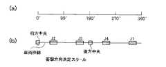
衝撃箇所図作成部33は、図5(a)に示すように、衝撃度検知センサー8の一周分を角度で定義した角度スケールθkを備え、かつこの角度スケールθkと同様な長さの衝撃方向決定スケール(図5(b))を備えている。衝撃方向決定スケールは、図4(a)の車輌の枠を伸ばして一直線で示したもので、その長さは角度スケールθkに一致させている。また、各タイヤの位置と車輌の前方中央、後方中央を衝撃方向決定スケールに定義している。
【0041】
この衝撃方向決定スケールに、受信した衝撃度の平均化範囲θi〜θpと、平均ピーク値の角度θkとを割り当てる。
【0042】
そして、この衝撃方向決定スケールを図4(a)に合わせて閉じた車輌事故画像Qiを生成し、この車輌事故画像Qiの中央を地図Gbの中心に合わせると共に、矢印付き軌跡kfが車輌事故画像Qiの中央ラインとなるように画像Qiを調整して地図Gbに定義する(この地図Gbを車輌衝突状況図付き地図Gp1(A車輌)、Gp2(B車輌)と称する)。
【0043】
両車輌事故図作成部34は、車輌衝突状況図付き地図Gp1が生成される毎に、相手側車輌の車輌番号又は証券番号が入力されたかどうかを判断し、入力されたときは、この番号に一致する相手側の車輌衝突状況図付き地図Gp2が生成されているかを判断する。Gp2が生成されている場合は、Gp2の地物の枠にGp1の枠を合わせた両車輌事故図付き地図Gpを生成する。
【0044】
DBサーバ17は、顧客情報、車輌事故地図Gp(Gp1、Gp2)等を保存する。前述の顧客情報は、証券番号と氏名と住所と電話番号と車番と車種等からなる。また、事故受付票のフォームを保存している。さらに、証券番号に対応する保険証書を記憶している。
【0045】
GIS19(地理情報システム)は、緯度経度が割り当てられた地図を備えている。この地図は、道路界、建物界、河川界等を組み合わせられ、点、線は緯度経度座標が割り振られたベクトルデータである。
【0046】
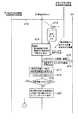
(動作説明)
上記のように構成された車輌事故状況自動収集システムの動作を図6、図7、図8のシーケンス図を用いて以下に説明する。本実施の形態では車輌Aのドライバーから通報を受けたとして説明する。また、車輌Aのデータには「a」を付加し、車輌Bのデータには「b」を付加する。
【0047】
図6に示すように、車輌に搭載された車輌事故映像格納・送信装置1は、イグニッションONによって起動する(d1)。すなわち、イグニッションONによって本装置の車輌事故映像格納ボックス4に電源が供給され、MPU28が各器機を起動状態にする初期設定を行う(d2)。
【0048】
MPU28は、起動に伴って各部をチェックすると共に、事故受付サイト3との回線を確立(携帯電話網へWAPプロトコルにて接続)する(d3)。
【0049】
そして、バックミラーの上部又は下部に取り付けられたCCDカメラ5からの画像Aia(ビデオキャプチャー22を用いる)と、カーナビ6からのGPSデータBia(緯度、経度、年月日、時刻)と、各種センサーデータCia(速度、タコメータ、ハンドル角度等)と、衝撃度・方向検知データDiaとを取り込み(d4、d5、d6、d7)、フラッシュメモリ23に記憶する(d8)。
【0050】
前述の衝撃度・方向検知データDiaは、衝撃方向算出部30によって得られている。つまり、所定レベルの衝撃を検知したときには、平均衝撃度を求めたときの平均化の範囲θi〜θpと、範囲θi〜θpの内でピークが集中している方向θkと、平均衝撃度とからなる。
【0051】
次に、MPU28は、1秒経過したかどうかを判断し(d9)、一秒経過したときは、衝撃度・方向検知データDiaがフラッシュメモリ23に保存されているかどうかを判定する(d10)。
【0052】
d10において、衝撃度・方向検知データDiaが保存されていないと判定したときは、再びCCDカメラ5からの画像Aia、カーナビ6からのGPSデータBia(緯度、経度、年月日、時刻)、各種センサーデータCia(速度、タコメータ、ハンドル角度等)を取り込み、フラッシュメモリ23に記憶する。
【0053】
また、d10において、衝撃度・方向検知データDiaが存在する(車輌が何かに衝突した)と判定したときは、フラッシュメモリ23の10フレーム分(10秒間前)を引き当て(d11)、衝突度・方向検知データDiaと共に、映像付き事故状況情報Riaとして携帯電話用通信IC24を用いて事故受付サイト3に送信させる(d12)。つまり、衝突を検知したときから10秒前分のGPSデータBia、CCDカメラ5の画像Aia、各種センサデータCiaと、予め記憶されている顧客情報(車番、証券番号、氏名、携帯電話番号)等が送信される。
【0054】
一方、事故受付サイト3のwebサーバ15は、httpプロトコルで通信を行い、図7に示すように、車輌事故映像格納・送信装置1からの映像付き事故状況情報RiaをDBサーバ17に保存する(d13)。この保存データは、事故通報が無い場合は、30分後にDBサーバ17が削除する。
【0055】
すなわち、事故受付サイト3のDBサーバ17には、車輌が何らかに当たって衝撃を受けたときの映像付き事故状況情報Riaのみが保存される。
【0056】
そして、実際に事故であった場合は、車輌Aのドライバーは事故受付サイト3に電話をかけて、車番又は証券番号、氏名、事故状況、相手側の車輌Bの車番等を知らせる。
【0057】
オペレータは、パソコンを操作して通報を受けた車番、証券番号又は携帯番号をキーとしてDBサーバ17の映像付き事故状況情報Riaを表示させる。
【0058】
このとき、同じ日に多数の映像付き事故状況リスト(10秒間分)がDBに存在する場合は、事故時画像引当処理部31が通報を受けた車番を有する全ての映像付き事故状況情報Riaを引き当て、これらの中かから通報を受けた時刻付近の映像付き事故状況情報を纏め(Rim〜Ris)、これをリストにして画面に表示する(図9(a)を参照)。
【0059】
そして、オペレータは、引き当てたリストの中の映像ファイル番号をクリックすると、事故時画像引当処理部31がDBサーバ17の中から映像ファイル番号にリンク付けされている事故状況の画像を、事故状況を確定させるための最適画像Apaを決定する。本実施の形態では図9(b)に示す映像付き事故状況情報Rpaの最適画像Apaが決定されたとする。
【0060】
この最適画像Apaの決定に伴って、事故位置地図作成部30は、映像付き事故状況情報Rpaを事故状況を示す最適なデータと決定する(d14)。
【0061】
この決定された映像付き事故状況情報RpaのGPSデータBipaの緯度、経度を中心とする半径20mの地図データGba(点、線には緯度経度座標が割り振られたベクトル)をGIS(地理情報システム)から読み込む(d15、d16)。
【0062】
次に、事故位置地図作成部30は、映像付き事故状況情報RpaのGPSデータ及びDBサーバ17の映像付き事故状況情報(Rim〜Ris)の各GPSデータの各緯度経度から車輌Aの移動軌跡を求め、この移動軌跡と移動方向とを示した矢印付き軌跡kfa(緯度経度が割り振られたベクトル)を地図データGba上に書き込む。
【0063】
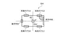
次に、衝撃箇所図作成部33は、決定された映像付き事故状況情報Rpaの衝撃度、衝撃度の平均化範囲θi〜θp、平均ピーク値の角度θkを読み、サイト3側で備えている図5(b)の衝撃方向決定スケール上にこれらを定義する(図10を参照)。そして、この衝撃方向決定スケールのJ1、J2、…前方向中央印、後方向中央印が図4(a)のJ1、J2、…前方向中央印、後方向中央印に合うようにして閉じた車輌事故画像Qiaを生成する(d17:図11参照)。この車輌事故画像Qiaの中央を地図Gbaの中心に合わせると共に、矢印付き軌跡kfaが車輌事故画像Qiaの中央ラインとなるように画像Qiaを調整して地図Gbaに定義する。すなわち、車輌衝突状況図付き地図Gp1を求める(d18:図12(a)を参照)。
【0064】
次に、両車輌事故図作成部34は、車輌衝突状況図付き地図Gp1が生成される毎に、DBサーバ17にB車輌の車輌衝突状況図付き地図Gp2が存在しているかどうかを判断する(d19)。
【0065】
B車輌の車輌衝突状況図付き地図Gp2が存在しない場合(つまり、相手側が何らかの理由で事故を通報できない場合)は、相手側の車輌衝突状況図付き地図Gp2が存在しないことを画面(例えばワークステーションの画面)に表示する(d20)。
【0066】
オペレータは、この表示によって、相手側の車番(ナンバープレートの番号)を入力して、事故位置地図作成部30、事故時画像引当部31、衝撃箇所図作成部33等を起動させる。
【0067】
つまり、オペレータが入力した相手側の車輌Bの車番を有する全ての映像付き事故状況情報Ribを引き当て、これらの中かからオペレータが入力した時間帯(通報を受けた時刻付近)の映像付き事故状況情報Rim〜Risを纏め、これをリストにして画面に表示する。
【0068】
そして、画面に表示したリストの中の映像ファイル番号が選択される毎に、DBサーバ17の中から選択された映像ファイル番号にリンク付けされている事故状況の画像を表示させ、画面に表示した画像が事故状況を確定させるための最適画像としてオペレータが決定したとき、その最適画像Apbの映像ファイル番号を有する映像付き事故状況情報RpbのGPSデータBipb(緯度、経度)を中心とする地図GbbをGIS19(地理情報システム)から引き当てる。
【0069】
また、映像付き状況情報RpbのGPSデータBipbを基準とし、これから例えば10個前まで(10秒間に相当)の各フレームに書き込まれているGPSデータの各緯度、経度に基づいて、映像付き事故状況情報Ribを送信した車輌の移動軌跡を求める。そして、この移動軌跡と移動方向を示した矢印付き軌跡kfbを、地図Gb2上に書き込む(図12(b))。
【0070】
車輌Bから受信した映像付き事故状況情報Ribの衝撃度の平均化範囲θi〜θpと、平均ピーク値の角度θkとを衝突方向決定スケールに割り当て、この衝撃方向決定スケールを図4(a)に合わせて閉じた車輌事故画像Qibを生成し、この車輌事故画像Qibの中央を地図Gbbの中心に合わせると共に、矢印付き軌跡kfbが車輌事故画像Qibの中央ラインとなるように画像Qibを調整して地図Gbbに定義して車輌衝突状況図付き地図Gp2を得る。
【0071】
また、d19において、B車輌の車輌衝突状況図付き地図Gp2がDBサーバ17に存在すると判定したときは、図8に示すように、両車輌事故図作成部34がGp2の地物の枠にGp1の枠を合わせた両車輌事故図付き地図Gpを生成する(d21)。つまり、図12に示すように、A車輌の車輌状況図付き地図Gp1と、B車輌の車輌状況図付き地図Gp2とが生成されている場合は、例えば道路界の線は緯度経度座標が割り振られたベクトルであるので、両方の地図Gp1、Gp2との合成は、同じ緯度経度座標の線同士を一致させて合成する。従って、図12の(c)に示すように、車輌A、Bが衝突したときの状況を示す画像(衝突方向、移動方向が示されている)が地図上に書き込まれることになる。
【0072】
そして、交通事故票作成部32は、A車輌の映像付き事故状況情報Rpaの最適画像Apaと、GPSデータBipaに基づく番地情報Paと、両車輌事故付き地図Gpとを事故受付票のフォームに組み込み(d22)、これを印刷させることによって図13に示す事故受付票を得る(d23)。
【0073】
すなわち、事故受付サイトでは、車輌A、Bとが衝突した場合は、自動的に車輌Aから見たときの事故時の車輌Bの映像Apbと、車輌Bから車輌Aを見たときの事故時の車輌Aの映像Apaと、衝突方向及び移動方向付き車輌Aの図と衝突方向及び移動方向付き車輌Bの図とを合成させた衝突現場の地図とが得られる。このため、後日現場検証しなくとも、ドライバ同士の報告と、事故受付票との内容の比較だけで立証が可能である。従って、保険会社では短時間で最適な保険金額を割り出すことが可能である。
【0074】
前述のボックス4のMPUの動作を図14のフローチャートを用いて補充する。MPU28はイグニッションONかどうかを判断する(S1)。
【0075】
ステップS1において、イグニッションONと判断したときは、事故受付サイトのURLコードを用いて回線を接続させる(S2)。
【0076】
次に、CCDカメラ5をON状態にする(S3)。そして、フラッシュメモリ23のフレーム番号を先頭番号にする(S4)。次に、一秒経過かどうかを判断する(S4)。ステップS4において、一秒経過と判断したときは、CCDカメラが撮影した画像を内部に取り込ませ、フレーム番号fiのフレームにその画像Aiを保存する(S5)。次に、カーナビ6のGPSデータBi、各種センサデータCiと、衝撃度・方向検知データDiとをフレーム番号fiのフレームに保存する(S6)。
【0077】
そして、このフレームへのデータの保存に伴って、衝撃度・方向検知データDiが保存されたかどうかを判断する(S7)。
【0078】
ステップS7において、衝撃度・方向検知データDi(衝撃を受けた)が存在するときは、現時点から10秒前までのf1、f2、…f10に保存されているデータと、メモリ29の証券番号、車番、携帯電話番号とを組み合わせた映像付き事故状況情報Riを送信させる(S8)。次に、イグニッションオフかどうかを判定する(S9)。イグニッションオフと判定したときは、f1、f2、…f10のフレームをクリアし(S10)、イグニションオフをサイト3に送信する(S11)。このとき、車番を送信する。
【0079】
一方、受付サイトは、映像付き事故状況情報Riを受信して記憶し、衝撃の値が大きな値を示しているときは、直ちに受信した映像付き事故状況情報Riを画面に表示してアラーム音を発生させる。
【0080】
これによって、サイトのオペレータは事故があったことが直ぐに分かり、また情報Riには携帯電話番号が含まれているからサイト側からドライバに電話をかけることが可能となる。
【0081】
なお、上記実施の形態では、イグニッションONした後は、CCDカメラをON状態にして1秒毎に画像を内部に取り込むとしたが、カーナビが危険エリア(交差点、カーブ)を通行中又は危険エリアに到達することが知らせられたときに、CCDカメラを動作させるようにしてもよい。
【0082】
さらに、上記実施の形態では、CCDカメラ5は前方を撮影するようにしたが、車輌の後部を撮影する後部用CCDカメラ、車輌の左右方向を撮影する左用CCDカメラ、右用CCDカメラを備え、これらの画像をフラッシュメモリに保存して、衝撃又は危険エリアに到達したときのみ送信してもよい。
【0083】
【発明の効果】
以上のように本発明によれば、衝突が発生したときは、自車輌からの相手車輌の映像、相手車輌からの自車輌の映像と、衝突方向を示したデータ、車番とが保険サイトに送信される。
【0084】
これらの映像付き情報の中から通報のあった車番の最適な事故映像(相手車輌、自車輌)とを選択さえて、映像付き情報に含まれる緯度経度から事故位置付近の一定範囲の地図を引き当て、この地図上に相手車輌、自車輌の衝突方向を示した車輌画像を定義し、これらを事故受付票に印刷する。
【0085】
このため、保険会社では双方の車輌事故時の状況を示す画像が印刷された事故受付票を直ちに得ることができるので、この画像から最適な保険金額の支払い額を容易に算定できるという効果が得られている。
【0086】
また、双方の映像、事故時の状況図が得られるので、支払い保険金額を正確に割り出すことが可能である。
【図面の簡単な説明】
【図1】本実施の形態の車輌事故状況自動収集システムの概略構成図である。
【図2】車輌事故映像格納ボックス4の概略構成図である。
【図3】車輌事故映像格納ボックス4の外観図である。
【図4】本実施の形態の衝撃度検知センサーの検知データを説明する説明図である。
【図5】本実施の形態の衝撃方向決定スケールを説明する説明図である。
【図6】本実施の形態の動作を説明するシーケンス図である。
【図7】本実施の形態の動作を説明するシーケンス図である。
【図8】本実施の形態の動作を説明するシーケンス図である。
【図9】本実施の形態のサイト側で表示される映像付き事故状況情報の説明図である。
【図10】本実施の形態の動作説明に用いる衝撃方向決定スケールの説明図である。
【図11】本実施の形態の衝撃方向を示した車輌画像の説明図である。
【図12】本実施の形態の車輌画像の合成を説明する説明図である。
【図13】本実施の形態で得られる事故受付票の説明図である。
【図14】本実施の形態の車輌事故映像格納・送信装置の動作を説明する説明図である。
【図15】従来の車載型事故映像及び音声記録装置の概略構成図である。
【符号の説明】
1 車輌事故映像格納・送信装置
2 ネットワーク
3 事故受付サイト
4 車輌事故映像格納ボックス
5 小型CCDカメラ
16 事故表自動作成装置
30 事故位置地図作成部
31 事故時画像引当部
32 交通事故票作成部
33 衝撃箇所図作成部
34 両車輌事故図作成部[0001]
BACKGROUND OF THE INVENTION
The present invention relates to a vehicle accident situation automatic collection system that sequentially captures and stores images outside a vehicle and transmits them to an insurance company site.
[0002]
[Prior art]
There is an apparatus that records images immediately before and after a vehicle traffic accident so that the situation at the time of the accident can be grasped.
[0003]
For example, as shown in FIG. 15, an in-vehicle accident video and audio recording device disclosed in Japanese Patent Application Laid-Open No. 9-39739 has a surveillance camera and a
[0004]
That is, the surveillance camera and the
[0005]
When a traffic accident occurs, the
[0006]
On the other hand, when an accident occurred, the car insurance policyholder contacted the “accident reception service” by telephone, and later described the situation at the time of the accident in the insurance company's accident reception table in detail.
[0007]
[Problems to be solved by the invention]
However, since the conventional in-vehicle accident video and audio recording device disclosed in the above Japanese Patent Laid-Open No. 9-39739 only registers video and audio in the storage device, the situation can be understood by analyzing the recording data of the storage device. It will be.
[0008]
That is, there is a problem that work for analyzing the recorded data occurs, resulting in high costs.
[0009]
In addition, insurance companies pay insurance claims for automobile accidents after they have received the accident reception table prepared by the driver, check the contents and prepare the necessary documents. At this time, when the conventional apparatus as described above is used, the insurance company analyzes the recorded data and confirms that the contents of the accident reception table are not different from the recorded data.
[0010]
Therefore, the insurance company needs a person who analyzes and visualizes the contents of the recorded data and a person who checks and compares this image with the contents of the accident reception table. .
[0011]
In addition, in the event of a vehicle accident, the driver will notify the relevant agency by telephone, but most of the time the driver will be in a panic immediately after the accident occurs, so the exact situation cannot be communicated to the other party. For example, there is a problem that even if a report is received from the insurance company, for example, the method of coping and the method of insurance procedure cannot be determined immediately.
[0012]
Also, for the driver, since the time has already passed when the accident reception table is created, there is a problem that the situation cannot be accurately reflected in the accident reception table.
[0013]
The present invention has been made to solve the above-mentioned problems. A vehicle accident in which the site of the insurance company can immediately obtain the situation at the time of the vehicle accident and can automatically create the necessary documents at the time of the accident without relying on the driver. The purpose is to obtain an automatic situation collection system.
[0014]
[Means for Solving the Problems]
The present inventionIn the vehicleThe provided terminal shoots and stores the video outside the vehicle, and the information with video including the video portion near the time of the collision is stored in the stored video.Communication networkThroughAccident reception siteLet the server collect the videoOutput the accident situation reception table from the printerIt is a vehicle accident situation automatic collection system.
[0015]
The terminal provided in the vehicle is
A CCD camera provided so as to be able to photograph the outside of the vehicle from the inside of the vehicle, and outputting video data of the outside of the vehicle;
It has a circular shape and is fixed at the center of the vehicle. The center of front of the vehicle is set to 0 degree direction, and the impact detection sensor is provided over the horizontal circumference of 360 degrees at intervals of 10 degrees from the position of the 0 degree direction. An impact detection sensor that outputs detection data of
A car navigation system with a GPS function that outputs GPS data including the latitude, longitude, date, and time of the vehicle on the map;
These are the boxes connected by their cables
In the vehicle.
The box comprises a computer, a keyboard and a display,
A memory storing customer information including a car number, a security number, a name, and a mobile phone number from the keyboard;
A flash memory, a computer, a video capture, and a communication IC that communicates with the server of the accident reception site, these are molded with a non-heated molding material in a housing,
The computer
Means for operating the CCD camera to periodically obtain the video data and operating the communication IC to establish a line with the server of the accident reception site;
Means for capturing video data from the CCD camera at a predetermined time interval by the video capture and sequentially storing the data in the flash memory together with the GPS data and the detection data from the impact detection sensor;
The detection data of the impact detection sensor is discretized and averaged to determine the impact, the range where the peak is concentrated is determined as the impact direction, and the impact / direction detection data including these is generated to generate the flash memory Means for storing in,
It is determined whether or not the impact level / detection data from the impact level detection sensor unit is stored in the flash memory every predetermined time, and when stored, the video data stored in the flash memory and Means for transmitting the degree of impact / direction detection data and the customer information to the server by the communication IC as accident state information with video;
Have
The server
A display unit;
Accident situation information with video from the terminal, a map with a vehicle collision situation diagram is stored, while the customer information and the form of the accident situation acceptance table and a security certificate database,
GIS with a map with latitude and longitude assigned to points and lines, combining at least road, building and river boundaries;
The server
The vehicle front center is 0 degrees, the vehicle rear center is 180 degrees, and the vehicle frame that goes around from the front center is shown as a straight line in the range of 0 to 360 degrees, and the front center The mark of the rear of the vehicle is provided at 180 degrees, the mark of the left front tire of the vehicle is between 0 degrees and 90 degrees, the mark of the right front tire is 270 degrees and 360 degrees (0 degrees) An impact direction determination scale which is provided between and passes these marks along the straight line;
Means for receiving the accident situation data with video via the communication network and storing it in the database; and when the vehicle number, security number or mobile phone number is input, the vehicle number, security number or mobile phone number The accident status information with video is searched from the database, and the time, date, and date of the GPS data of the searched accident status information with video are stored in the database, the vehicle number, the security number, the name, and the Means for displaying on the display unit data corresponding to the file number of the video data of the video accident information with video, and when the file number of the list displayed on the display unit is selected, the selected file Link to numberThe means for making the image data that has been recorded the optimum accident situation image, and the degree of impact and the direction of the impact detection / direction detection data associated with the optimized image data are read, and these are used as the angles. Vehicle for indicating the angle of the corresponding impact direction determination scale, and after the impact degree / direction detection data is defined in the impact direction determination scale, the scale is closed to show a plan view of the vehicle and the impact direction Means for obtaining an accident image, the optimized accident situation image, the address information based on the latitude and longitude of the GPS data, the car number, the security number, the name of the customer information, and the optimum accident situation image Means for incorporating into the fountain of the accident reception table and printing from the printer;The main point is that
[0016]
DETAILED DESCRIPTION OF THE INVENTION
FIG. 1 is a schematic configuration diagram of a vehicle accident situation automatic collection system of the present embodiment. This vehicle accident situation automatic collection system is a system comprising a vehicle accident video storage /
[0017]
As shown in FIGS. 1 and 2, the vehicle accident image storage /
[0018]
In FIG. 1, it is assumed that the vehicle accident video storing /
[0019]
The
[0020]
That is, for both the A vehicle and the B vehicle, the vehicle
[0021]
On the other hand, the accident reception site 3 includes a
[0022]
(Details of each device)
The vehicle accident
[0023]
Further, the vehicle accident
[0024]
The above-described
[0025]
Further, the impact degree direction calculation unit 30 discretizes and averages the detection data from the
[0026]
The impact degree / direction detection data Di will be described with reference to FIG. As shown in FIG. 4A, the
[0027]
That is, for example, when a collision is received from the left front, detection data is input to the
[0028]
Then, these detection data are discretized and averaged to obtain an average impact degree. When the average impact degree exceeds a reference (impact of 50 kg weight (load applied to the vehicle) or more), FIG. ), The average range of impact θi to θp when the average impact level is obtained, the direction θk in which peaks are concentrated in the range θi to θp, and the average impact level are detected. Transmit as data Di. The standard impact degree may be in the range of 30 kg weight to 70 kg weight.
[0029]
When the ignition is turned on, the
[0030]
At this time, various sensor information (tachometer, speed, etc.) and GPS information Bi obtained by the car navigation 6 are stored in the
[0031]
Further, when the
[0032]
On the other hand, the accident card automatic creation device 16 of the accident reception site 3 includes an accident location map creation unit 30, an accident time
[0033]
The
[0034]
Then, every time an image file number in the list displayed on the screen is selected, the accident
[0035]
Then, when the operator determines that the image displayed on the screen is the optimum image for determining the accident situation, the accident situation information Rp with video having the video file number of the optimum image is passed to the accident location map creation unit 30.
[0036]
The accident location map creation unit 30 allocates a map Gb centered on the GPS data Bip (latitude, longitude) of the accident situation information Rp with video passed from the accident location map creation unit 30 from the GIS 19 (geographic information system).
[0037]
In addition, the accident location map creation unit 30 uses the GPS data Bip of the situation information Rp with video as a reference, for example, each latitude and longitude of the GPS data written in each frame up to 10 times before (equivalent to 10 seconds). Based on the above, the movement trajectory of the vehicle that has transmitted the accident situation information Ri with video is obtained. And the locus | trajectory kf with the arrow which showed this movement locus | trajectory and a moving direction is written on the map Gb.
[0038]
The traffic accident form
[0039]
Further, the date and time of the GPS data Bip of the selected accident situation information Rp with video are incorporated in a predetermined column. Furthermore, a car number, a security number, etc. are incorporated in a predetermined column.
[0040]
As shown in FIG. 5A, the impact location
[0041]
An average range θi to θp of the received impact level and an average peak value angle θk are assigned to the impact direction determination scale.
[0042]
Then, a vehicle accident image Qi having the impact direction determination scale matched with FIG. 4A is generated, the center of the vehicle accident image Qi is aligned with the center of the map Gb, and the locus kf with an arrow is the vehicle accident image. The image Qi is adjusted so as to be the center line of Qi and defined in the map Gb (this map Gb is referred to as a vehicle collision situation map Gp1 (A vehicle), Gp2 (B vehicle)).
[0043]
Each time the vehicle accident
[0044]
The
[0045]
The GIS 19 (geographic information system) includes a map to which latitude and longitude are assigned. This map is vector data in which road boundaries, building boundaries, river boundaries, etc. are combined, and points and lines are assigned latitude and longitude coordinates.
[0046]
(Description of operation)
The operation of the vehicle accident situation automatic collection system configured as described above will be described below with reference to the sequence diagrams of FIGS. In the present embodiment, it is assumed that a report is received from the driver of vehicle A. Further, “a” is added to the data of the vehicle A, and “b” is added to the data of the vehicle B.
[0047]
As shown in FIG. 6, the vehicle accident video storing /
[0048]
The
[0049]
Then, an image Aia (using the video capture 22) from the
[0050]
The impact degree / direction detection data Dia described above is obtained by the impact direction calculation unit 30. That is, when a predetermined level of impact is detected, the average range of impact θi to θp when the average impact level is obtained, the direction θk in which the peaks are concentrated in the range θi to θp, and the average impact level are calculated. Become.
[0051]
Next, the
[0052]
If it is determined in d10 that the impact / direction detection data Dia is not stored, the image Aia from the
[0053]
When it is determined at d10 that the impact degree / direction detection data Dia exists (the vehicle has collided with something), 10 frames (10 seconds before) of the
[0054]
On the other hand, the
[0055]
That is, the
[0056]
In the case of an accident, the driver of the vehicle A calls the accident reception site 3 and informs the vehicle number or securities number, name, accident situation, vehicle number of the other vehicle B, and the like.
[0057]
The operator operates the personal computer to display the accident situation information Ria with video of the
[0058]
At this time, if a large number of accident situation lists with video (for 10 seconds) exist in the DB on the same day, all accident situation information Ria with video having the vehicle number for which the accident image
[0059]
Then, when the operator clicks the video file number in the assigned list, the accident image
[0060]
With the determination of the optimum image Apa, the accident position map creation unit 30 determines the accident situation information Rpa with video as the optimum data indicating the accident situation (d14).
[0061]
Map data Gba (vector in which latitude and longitude coordinates are assigned to points and lines) having a radius of 20 m centered on the latitude and longitude of the GPS data Bipa of the determined accident situation information Rpa with video is defined as GIS (geographic information system). (D15, d16).
[0062]
Next, the accident location map creation unit 30 determines the movement trajectory of the vehicle A from each latitude and longitude of the GPS data of the accident situation information Rpa with video and the GPS data of the accident situation information (Rim to Ris) with video of the
[0063]
Next, the impact location
[0064]
Next, the vehicle accident
[0065]
When the map Gp2 with the vehicle collision situation diagram of the B vehicle does not exist (that is, when the other party cannot report an accident for some reason), a screen (for example, a workstation) (D20).
[0066]
Based on this display, the operator inputs the other party's vehicle number (number plate number) and activates the accident location map creation unit 30, the accident time
[0067]
That is, all the accident situation information Rib with the image having the vehicle number of the opposite vehicle B input by the operator is allocated, and the accident with the image in the time zone (near the time when the notification is received) entered by the operator from among them The status information Rim to Ris are collected and displayed as a list on the screen.
[0068]
Each time a video file number in the list displayed on the screen is selected, an image of the accident situation linked to the video file number selected from the
[0069]
Moreover, based on the GPS data Bipb of the situation information Rpb with video as a reference, the accident situation with video based on the latitude and longitude of the GPS data written in each frame up to 10 times before (equivalent to 10 seconds), for example The movement trajectory of the vehicle that transmitted the information Rib is obtained. And the locus | trajectory kfb with an arrow which showed this movement locus | trajectory and a moving direction is written on map Gb2 (FIG.12 (b)).
[0070]
The impact degree averaging range θi to θp of the accident situation information Rib with video received from the vehicle B and the average peak value angle θk are assigned to the collision direction determination scale, and this impact direction determination scale is shown in FIG. A closed vehicle accident image Qib is generated and the center of the vehicle accident image Qib is adjusted to the center of the map Gbb, and the image Qib is adjusted so that the locus kfb with the arrow is the center line of the vehicle accident image Qib. A map Gp2 with a vehicle collision situation diagram is obtained by defining the map Gbb.
[0071]
If it is determined at d19 that the map Gp2 with the vehicle collision situation map of the B vehicle exists in the
[0072]
Then, the traffic accident
[0073]
That is, in the accident reception site, when the vehicles A and B collide, the image Apb of the vehicle B when the vehicle A is automatically viewed from the vehicle A and the accident when the vehicle A is viewed from the vehicle B The image Apa of the vehicle A and a map of the collision site obtained by combining the figure of the vehicle A with the collision direction and the movement direction and the figure of the vehicle B with the collision direction and the movement direction are obtained. For this reason, it is possible to prove by only comparing the contents of the reports between the drivers and the accident reception slip without performing on-site verification at a later date. Therefore, the insurance company can determine the optimal insurance amount in a short time.
[0074]
The operation of the MPU in
[0075]
If it is determined in step S1 that the ignition is ON, the line is connected using the URL code of the accident reception site (S2).
[0076]
Next, the
[0077]
Then, it is determined whether or not the impact / direction detection data Di has been saved as the data is saved in this frame (S7).
[0078]
In step S7, when there is impact degree / direction detection data Di (impacted), the data stored in f1, f2,... F10 up to 10 seconds before the present time, the security number in the
[0079]
On the other hand, the reception site receives and stores the accident situation information Ri with a video, and when the impact value indicates a large value, immediately displays the received accident situation information Ri with a video on the screen and generates an alarm sound. generate.
[0080]
As a result, the operator of the site immediately knows that an accident has occurred, and since the mobile phone number is included in the information Ri, it is possible to call the driver from the site side.
[0081]
In the above embodiment, after the ignition is turned on, the CCD camera is turned on and the image is taken in every second. However, the car navigation system is passing through the danger area (intersection, curve) or in the danger area. The CCD camera may be operated when notified of the arrival.
[0082]
Furthermore, in the above embodiment, the
[0083]
【The invention's effect】
As described above, according to the present invention, when a collision occurs, the image of the opponent vehicle from the own vehicle, the image of the own vehicle from the opponent vehicle, the data indicating the collision direction, and the vehicle number are displayed on the insurance site. Sent.
[0084]
Even from the information with video, select the optimal accident video (partner vehicle, own vehicle) of the car number that was reported, and map a certain range near the accident location from the latitude and longitude included in the information with video The vehicle image indicating the collision direction of the partner vehicle and the own vehicle is defined on the map, and these are printed on the accident reception slip.
[0085]
For this reason, the insurance company can immediately obtain an accident reception slip printed with an image showing the situation at the time of both vehicle accidents. Therefore, it is possible to easily calculate the optimal amount of insurance payment from this image. It has been.
[0086]
In addition, since both images and situation diagrams at the time of the accident are obtained, it is possible to accurately determine the amount of insurance paid.
[Brief description of the drawings]
FIG. 1 is a schematic configuration diagram of a vehicle accident situation automatic collection system according to an embodiment of the present invention.
FIG. 2 is a schematic configuration diagram of a vehicle accident
FIG. 3 is an external view of a vehicle accident
FIG. 4 is an explanatory diagram illustrating detection data of an impact detection sensor according to the present embodiment.
FIG. 5 is an explanatory diagram for explaining an impact direction determination scale according to the present embodiment;
FIG. 6 is a sequence diagram for explaining the operation of the present embodiment;
FIG. 7 is a sequence diagram for explaining the operation of the present embodiment;
FIG. 8 is a sequence diagram for explaining the operation of the present embodiment;
FIG. 9 is an explanatory diagram of accident situation information with video displayed on the site side according to the present embodiment.
FIG. 10 is an explanatory diagram of an impact direction determination scale used for explaining the operation of the present embodiment.
FIG. 11 is an explanatory diagram of a vehicle image showing an impact direction according to the present embodiment.
FIG. 12 is an explanatory diagram illustrating composition of vehicle images according to the present embodiment.
FIG. 13 is an explanatory diagram of an accident acceptance slip obtained in the present embodiment.
FIG. 14 is an explanatory diagram for explaining the operation of the vehicle accident video storing / transmitting apparatus according to the present embodiment;
FIG. 15 is a schematic configuration diagram of a conventional in-vehicle accident video and audio recording apparatus.
[Explanation of symbols]
1 Vehicle accident video storage / transmission device
2 network
3 Accident reception site
4 Vehicle accident video storage box
5 Small CCD camera
16 Accident table automatic creation device
30 Accident Location Map Creation Department
31 Accident Image Reserve Department
32 Traffic accident card making department
33 Impact location diagram creation part
34 Vehicle accident drawing section
Claims (6)
Translated fromJapanese前記自車輌に設けられた端末は、
前記車輌内から車輌の外を撮影可能に設けられ、この車輌の外を撮影した映像データを出力するCCDカメラと、
円形状であり、車輌内の中央部に固定され、車輌の前方中央を0度方向として、この0度方向の位置から10度間隔に衝撃度検知センサを水平周囲360度に渡って設け、これらの検知データを出力する衝撃度検知センサ部と、
地図上の自車輌の緯度、経度及び年月日、時刻を含むGPSデータを出力するGPS機能付きカーナビと、
これらに、それぞれのケーブルで接続したボックスと
を車輌内に備えてなり、
前記ボックスは、コンピュータ、キーボード及び表示器を備え、
前記キーボードからの車番、証券番号、氏名、携帯電話番号を含む顧客情報が記憶されたメモリと、
フラッシュメモリと、コンピュータと、ビデオキャプチャーと、前記事故受付サイトのサーバと通信をする通信ICとを備えて、これらを筐体内に非加熱モールド材でモールドされており、
前記コンピュータは、
前記CCDカメラを動作させて前記映像データを定期的に得ると共に、前記通信ICを動作させて前記事故受付サイトのサーバと回線を確立させる手段と、
一定時間毎に、前記CCDカメラからの映像データを前記ビデオキャプチャーで取り込み、前記GPSデータと前記衝撃度検知センサからの検知データと共に前記フラッシュメモリに順次保存する手段と、
前記衝撃度検知センサの検知データを、離散化平均して衝撃度を求め、最もピークが集中している範囲を衝撃方向として求め、これらを含む衝撃度・方向検知データを生成して前記フラッシュメモリに保存する手段と、
前記一定時間毎に前記衝撃度検知センサ部からの衝撃度・検知データが前記フラッシュメモリに保存されているかどうかを判断し、保存されているときは、前記フラッシュメモリに保存された前記映像データ及び衝撃度・方向検知データ並びに前記顧客情報を映像付き事故状況情報として前記通信ICによって前記サーバに送信する手段と
を有し、
前記サーバは、
表示部と、
前記端末からの映像付き事故状況情報、車輌衝突状況図付き地図が記憶される一方、前記顧客情報及び事故状況受付表のフォーム並びに証券証書が記憶されたデータベースと、
少なくとも道路界、建物界、河川界を組合せて、点と線に緯度経度を割り振った地図を備えたGISと、
前記サーバは、
前記車輌の前方中央を0度、車輌後方中央を180度とし、前記前方中央から一周させた車輌枠を0度から360度の範囲で直線で示し、かつこの直線の0度の位置に前方中央の印を、180度に車輌の後方中央の印を設けると共に、車輌の左前タイヤの印を0度と90度との間に、右前タイヤの印を270度と360度(0度)との間に設け、これらの印を前記直線で通過させてた衝撃方向決定スケールと、
前記通信網を介して前記映像付き事故状況データを受信して前記データベースに保存する手段と、
前記車番、証券番号又は携帯電話番号が入力されたとき、該車番、証券番号又は携帯電話番号を有する前記映像付き事故状況情報を前記データベースから検索し、該検索した映像付き事故状況情報のGPSデータの時刻、年月日に、前記データベースに保存されている車番、証券番号、氏名及び前記映像付き事故情報の前記映像データのファイル番号を対応させたデータをリストにして前記表示部に表示させる手段と、
前記表示部に表示したリストのファイル番号が選択されたとき、該選択されたファイル番号にリンク付けされている映像データを最適な事故状況画像とする手段と、
前記最適とされた映像データに関係づけられている衝撃度・方向検知データの衝撃度及び衝撃方向を読み、これらをその角度に対応する前記衝撃方向決定スケールの角度に定義する手段と、
前記衝撃度・方向検知データが前記衝撃方向決定スケールに定義された後に、このスケールを閉じて車輌の平面図及び前記衝撃方向を示す車輌事故画像を得る手段と、
前記最適とされた事故状況画像と、前記GPSデータの緯度経度に基づく番地情報と前記顧客情報の車番、証券番号、氏名並びに前記最適とされた事故状況画像を前記事故受付表のフームに組み込んで前記プリンタから印刷させる手段と
を有することを特徴とする車輌事故状況自動収集システム。Terminal providedin the vehicletanks accumulates by shooting the image outside the vehicle,of the accumulatedaccidents reception site via thecommunication network video with information including an image portion in the vicinity of collision among the image serverA vehicle accident situation automatic collection system that collectsand outputs theaccident situation reception table with videofrom a printer ,
The terminal provided in the vehicle is
A CCD camera provided so as to be able to photograph the outside of the vehicle from the inside of the vehicle, and outputting video data of the outside of the vehicle;
It has a circular shape and is fixed at the center of the vehicle. The center of front of the vehicle is set to 0 degree direction, and the impact detection sensor is provided over the horizontal circumference of 360 degrees at intervals of 10 degrees from the position of the 0 degree direction. An impact detection sensor that outputs detection data of
A car navigation system with a GPS function that outputs GPS data including the latitude, longitude, date, and time of the vehicle on the map;
These are the boxes connected by their cables
In the vehicle,
The box comprises a computer, a keyboard and a display,
A memory storing customer information including a car number, a security number, a name, and a mobile phone number from the keyboard;
A flash memory, a computer, a video capture, and a communication IC that communicates with the server of the accident reception site, these are molded with a non-heated molding material in a housing,
The computer
Means for operating the CCD camera to periodically obtain the video data and operating the communication IC to establish a line with the server of the accident reception site;
Means for capturing video data from the CCD camera at a predetermined time interval by the video capture and sequentially storing the data in the flash memory together with the GPS data and the detection data from the impact detection sensor;
The detection data of the impact detection sensor is discretized and averaged to determine the impact, the range where the peak is concentrated is determined as the impact direction, and the impact / direction detection data including these is generated to generate the flash memory Means for storing in,
It is determined whether or not the impact level / detection data from the impact level detection sensor unit is stored in the flash memory every predetermined time, and when stored, the video data stored in the flash memory and Means for transmitting the degree of impact / direction detection data and the customer information to the server by the communication IC as accident state information with video;
Have
The server
A display unit;
Accident situation information with video from the terminal, a map with a vehicle collision situation diagram is stored, while the customer information and the form of the accident situation acceptance table and a security certificate database,
GIS with a map with latitude and longitude assigned to points and lines, combining at least road, building and river boundaries;
The server
The vehicle front center is 0 degrees, the vehicle rear center is 180 degrees, and the vehicle frame that goes around from the front center is shown as a straight line in the range of 0 to 360 degrees, and the front center The mark of the rear of the vehicle is provided at 180 degrees, the mark of the left front tire of the vehicle is between 0 degrees and 90 degrees, the mark of the right front tire is 270 degrees and 360 degrees (0 degrees) An impact direction determination scale which is provided between and passes these marks along the straight line;
Means for receiving the accident situation data with video via the communication network and storing it in the database;
The vehicle number, when the policy number or mobile phone number has been entered,該車number,to search for the video with the accident situation information with theSecurities number or mobilephonenumber from the database, the search and the video with the accident situation information The display unit displays a list of data that associates the time, date, and date of the GPS data with the vehicle number, security number, name, and file number of the video data of the accident information with video stored in the database. Means for displaying
When the file number of the list displayed on the display unit is selected, means for making the video data linked to the selected file number an optimal accident situation image;
Means for reading the impact degree and impact direction of the impact degree / direction detection data related to the optimized video data, and defining them as angles of the impact direction determination scale corresponding to the angles;
Means for obtaining a vehicle accident image indicating a plan view of the vehicle and the impact direction by closing the scale after the impact degree / direction detection data is defined in the impact direction determination scale;
The optimum accident situation image, the address information based on the latitude and longitude of the GPS data, the car number, the security number, the name of the customer information, and the optimum accident situation image are incorporated into the fountain of the accident reception table. And a vehicle accident situation automatic collection systemcomprising: means for printing from the printer .
前記最適な事故状況画像が選択されたとき、この画像にリンク付けされている映像付き事故状況情報のGPSデータの緯度、経度を中心とした一定範囲の地図を前記GISから読み込む手段と、
前記データベースの映像付き事故状況情報の各GPSデータの各緯度経度から車輌の移動軌跡を求める手段と、
前記求めた移動軌跡を示す矢印を前記読み込んだ一定範囲の地図に書き込む手段と、
前記車輌事故画像の中央を前記一定範囲の地図の中心に合わせると共に、前記矢印が前記車輌事故画像の中央ラインになるようにこの画像を調整して前記一定範囲の地図に定義し、これを前記事故状況とする手段と
を有することを特徴とする請求項1記載の車輌事故状況自動収集システム。The server
Means for reading from the GIS a map of a certain range centered on the latitude and longitude of the GPS data of the accident situation information with video linked to the image when the optimum accident situation image is selected;
Means for determining the movement trajectory of the vehicle from each latitude and longitude of each GPS data of the accident situation information with video of the database;
Means for writing an arrow indicating the obtained movement trajectory into the read map of the certain range;
The center of the vehicle accident image is aligned with the center of the map of the certain range, and the image is adjusted so that the arrow is the center line of the vehicle accident image and defined in the map of the certain range, The vehicle accident status automatic collection system according to claim 1, further comprising means for setting an accident status.
速度メータ、タコメータ、操作ボックス、アクセルの各センサに接続され、これらの検知データを前記フラッシュメモリに記憶し、これを前記映像付き車輌状況情報に含ませて送信させる手段と
を有することを特徴とする請求項1又は2記載の車輌事故状況自動収集システム。The box is
Means for connecting to each sensor of a speed meter, tachometer, operation box, and accelerator, storing the detected data in the flash memory, and transmitting the detected data in the vehicle status information with video. 3. The vehicle accident situation automatic collection system according to claim 1 or 2.
前記CCDを車輌のイグニッションオンに伴って動作状態にすると共に、前記通信ICによって前記サーバと通信回線を確立させる手段を
有することを特徴とする請求項1、2又は3記載の車輌事故状況自動収集システム。The box is
The vehicle according to claim 1, 2 or 3, further comprising means for setting the CCD in an operation state when the vehicle is turned on and establishing a communication line with the server by the communication IC. Accident situation automatic collection system.
一秒経過したかどうかを判断し、一秒経過したときに、前記衝撃度・検知データがフラッシュメモリに保存されているかどうかを判断する手段と、
前記衝撃度・検知データが保存されている場合は、現時点から10秒前までの映像データを前記映像付き事故状況情報に含ませて送信させる手段と
を有することを特徴とする請求項1乃至4記載の車輌事故状況自動収集システム。The box is
Means for determining whether one second has elapsed, and means for determining whether the impact level / detection data is stored in the flash memory when one second has elapsed;
Means for transmitting the video data up to 10 seconds before the present in the accident situation information with video when the impact level / detection data is stored;
5. The vehicle accident situation automatic collection system according to claim 1, further comprising:
前記サーバは、 The server
相手の車番が入力する毎に、この車番から前記データベースに保存されている前記相手車輌の前記映像データから最適なものを選択させ、この映像データにリンク付けされてい Each time the opponent's car number is entered, the most appropriate video data of the opponent vehicle stored in the database is selected from this car number and linked to this video data.るGPSデータに基づいて相手車輌の車輌衝突状況図付き地図を前記各手段を起動させて生成させ、この相手車輌の衝突状況付き地図と前記自車輌の衝突状況図付き地図とを合成した両車輌事故図付き地図を生成し、これを前記表のフォームに組み込む手段とBoth vehicles which generate the map with the vehicle collision situation diagram of the opponent vehicle based on the GPS data generated by activating each of the means, and synthesize the map with the collision situation map of the opponent vehicle and the map with the collision situation diagram of the own vehicle Means for generating a map with an accident map and incorporating it into the form of the table;
を有することを特徴とする請求項1乃至5記載の車輌事故状況自動収集システム。The vehicle accident situation automatic collection system according to claim 1, wherein the vehicle accident situation automatic collection system is provided.
Priority Applications (1)
| Application Number | Priority Date | Filing Date | Title |
|---|---|---|---|
| JP2002178901AJP3798996B2 (en) | 2002-06-19 | 2002-06-19 | Vehicle accident situation automatic collection system |
Applications Claiming Priority (1)
| Application Number | Priority Date | Filing Date | Title |
|---|---|---|---|
| JP2002178901AJP3798996B2 (en) | 2002-06-19 | 2002-06-19 | Vehicle accident situation automatic collection system |
Publications (2)
| Publication Number | Publication Date |
|---|---|
| JP2004017901A JP2004017901A (en) | 2004-01-22 |
| JP3798996B2true JP3798996B2 (en) | 2006-07-19 |
Family
ID=31176484
Family Applications (1)
| Application Number | Title | Priority Date | Filing Date |
|---|---|---|---|
| JP2002178901AExpired - LifetimeJP3798996B2 (en) | 2002-06-19 | 2002-06-19 | Vehicle accident situation automatic collection system |
Country Status (1)
| Country | Link |
|---|---|
| JP (1) | JP3798996B2 (en) |
Families Citing this family (28)
| Publication number | Priority date | Publication date | Assignee | Title |
|---|---|---|---|---|
| US9311676B2 (en) | 2003-09-04 | 2016-04-12 | Hartford Fire Insurance Company | Systems and methods for analyzing sensor data |
| US7610210B2 (en) | 2003-09-04 | 2009-10-27 | Hartford Fire Insurance Company | System for the acquisition of technology risk mitigation information associated with insurance |
| US7711584B2 (en) | 2003-09-04 | 2010-05-04 | Hartford Fire Insurance Company | System for reducing the risk associated with an insured building structure through the incorporation of selected technologies |
| US7783505B2 (en) | 2003-12-30 | 2010-08-24 | Hartford Fire Insurance Company | System and method for computerized insurance rating |
| US8090599B2 (en) | 2003-12-30 | 2012-01-03 | Hartford Fire Insurance Company | Method and system for computerized insurance underwriting |
| JP2005269256A (en)* | 2004-03-18 | 2005-09-29 | Nec Corp | Image storage system and method, and in-vehicle device |
| JP2007096671A (en)* | 2005-09-28 | 2007-04-12 | Mitsubishi Electric Corp | In-vehicle monitoring recorder and image data transfer method for in-vehicle monitoring recorder |
| WO2007094191A1 (en)* | 2006-02-16 | 2007-08-23 | Pioneer Corporation | Mobile object insurance service supporting method, mobile object insurance service supporting program, recording medium, and mobile object insurance service supporting device |
| EP2000394A2 (en)* | 2006-03-29 | 2008-12-10 | Fujitsu Microelectronics Limited | Recording device and recording method |
| JP4729440B2 (en)* | 2006-06-07 | 2011-07-20 | 日立オートモティブシステムズ株式会社 | Communication system, communication terminal, and information processing apparatus |
| WO2008026290A1 (en)* | 2006-09-01 | 2008-03-06 | Pioneer Corporation | Information recording device, information recording method, information recording program, and computer-readable recording medium |
| JP4986135B2 (en)* | 2007-03-22 | 2012-07-25 | 株式会社エクォス・リサーチ | Database creation device and database creation program |
| KR20090040622A (en)* | 2007-10-22 | 2009-04-27 | 한국전자통신연구원 | Method and device for providing vehicle accident information |
| US9665910B2 (en) | 2008-02-20 | 2017-05-30 | Hartford Fire Insurance Company | System and method for providing customized safety feedback |
| KR101088650B1 (en)* | 2009-11-26 | 2011-12-01 | 아진산업(주) | Accident recorder using vehicle information and video |
| KR101067599B1 (en) | 2010-01-18 | 2011-09-27 | (주)나노포인트 | Vehicle black box device that transmits low and high resolution video information to remote locations |
| KR101157864B1 (en)* | 2010-03-31 | 2012-06-22 | 권만준 | Method for Making Automobile Driving Record Executed on Smart Phone |
| US9460471B2 (en) | 2010-07-16 | 2016-10-04 | Hartford Fire Insurance Company | System and method for an automated validation system |
| KR20120063389A (en)* | 2010-12-07 | 2012-06-15 | 쓰리에이치비젼주식회사 | Vehicle accident alarm system and method thereof |
| JP5533626B2 (en)* | 2010-12-16 | 2014-06-25 | 株式会社デンソー | Drive recorder system |
| KR101071914B1 (en)* | 2011-03-16 | 2011-10-11 | 강재민 | Automobile crash notification system and method |
| KR101498534B1 (en)* | 2013-02-27 | 2015-03-04 | 강재민 | Noticing system for car collisions being accummulated a mileage and method therefor |
| CN103500503B (en)* | 2013-09-17 | 2016-09-07 | 北京中广睛彩导航科技有限公司 | A kind of accurate road condition analyzing method and system based on mass-rent pattern |
| WO2015060805A1 (en)* | 2013-10-22 | 2015-04-30 | Ant Bilisim Elektronik Ve Enerji Teknolojileri Sanayi Ve Ticaret Anonim Sirketi | A system for processing data obtained from black boxes |
| JP6326784B2 (en)* | 2013-11-26 | 2018-05-23 | 富士通株式会社 | Analysis support program, analysis support method, and analysis support apparatus |
| JP6595842B2 (en)* | 2015-08-25 | 2019-10-23 | 東京海上日動火災保険株式会社 | Information processing technology related to customer service in the event of an accident |
| TWI613115B (en)* | 2017-03-30 | 2018-02-01 | H P B Optoelectronic Co Ltd | Vehicle warning system |
| JP7206246B2 (en)* | 2020-12-09 | 2023-01-17 | あいおいニッセイ同和損害保険株式会社 | Program and information processing method |
Family Cites Families (3)
| Publication number | Priority date | Publication date | Assignee | Title |
|---|---|---|---|---|
| JPH0939739A (en)* | 1995-07-25 | 1997-02-10 | Satoki Takeda | On-vehicle accident image and voice recording device |
| JPH11298853A (en)* | 1998-04-13 | 1999-10-29 | Matsushita Electric Ind Co Ltd | Operation status recording device |
| JP2001118175A (en)* | 1999-10-14 | 2001-04-27 | Matsushita Electric Ind Co Ltd | Emergency call system and in-vehicle device |
- 2002
- 2002-06-19JPJP2002178901Apatent/JP3798996B2/ennot_activeExpired - Lifetime
Also Published As
| Publication number | Publication date |
|---|---|
| JP2004017901A (en) | 2004-01-22 |
Similar Documents
| Publication | Publication Date | Title |
|---|---|---|
| JP3798996B2 (en) | Vehicle accident situation automatic collection system | |
| CN106710291B (en) | Parking space obtaining method and device for parking lot | |
| US9067565B2 (en) | System and method for evaluating driver behavior | |
| JP4416374B2 (en) | Insurance premium setting method, insurance premium setting program, and insurance premium setting device | |
| US20050073436A1 (en) | Method and system for alerting a patrol officer of a wanted vehicle | |
| JP2002133117A (en) | Automobile insurance system, automobile insurance center and automobile | |
| US8260533B2 (en) | Traffic monitoring system | |
| US20210342946A1 (en) | Using a Distributed Ledger for Line Item Determination | |
| US20210326992A1 (en) | Using a Distributed Ledger for Subrogation Recommendations | |
| US20180108252A1 (en) | Device known as real time total control digital tachograph (tcdt) for vehicle and other nearby vehicles by means of cameras and mobile connections | |
| US20030212567A1 (en) | Witness information service with image capturing and sharing | |
| US20080294690A1 (en) | System and Method for Automatically Registering a Vehicle Monitoring Device | |
| US20030163233A1 (en) | Automatic vehicle management apparatus and method using wire and wireless communication network | |
| US20030210806A1 (en) | Navigational information service with image capturing and sharing | |
| CN110009900A (en) | A kind of vehicle monitoring method and system | |
| JP2002518753A (en) | Roadside inspection device for toll charging device installed in the vehicle | |
| JP5585194B2 (en) | Accident situation recording system | |
| JP4214841B2 (en) | Ambient situation recognition system | |
| US12159323B2 (en) | Vehicle monitoring apparatus, vehicle monitoring system, and vehicle monitoring method | |
| EP1975899A1 (en) | A method, system and device for detecting, protecting against and reporting traffic law violations | |
| CN104050814A (en) | road management auxiliary method and device, and road management auxiliary program | |
| KR20130108928A (en) | Method for gathering of car accident, apparatus and system for the same | |
| JP2004013234A (en) | Automatic collection system of vehicle accident circumstance information | |
| JP4119106B2 (en) | In-vehicle machine | |
| US12248663B1 (en) | System on board an on-road vehicle for identifying, tagging and reporting hazardous drivers in the vicinity of a host vehicle |
Legal Events
| Date | Code | Title | Description |
|---|---|---|---|
| A621 | Written request for application examination | Free format text:JAPANESE INTERMEDIATE CODE: A621 Effective date:20050601 | |
| A711 | Notification of change in applicant | Free format text:JAPANESE INTERMEDIATE CODE: A711 Effective date:20050610 | |
| A871 | Explanation of circumstances concerning accelerated examination | Free format text:JAPANESE INTERMEDIATE CODE: A871 Effective date:20051104 | |
| A975 | Report on accelerated examination | Free format text:JAPANESE INTERMEDIATE CODE: A971005 Effective date:20051122 | |
| A131 | Notification of reasons for refusal | Free format text:JAPANESE INTERMEDIATE CODE: A131 Effective date:20051206 | |
| A521 | Request for written amendment filed | Free format text:JAPANESE INTERMEDIATE CODE: A523 Effective date:20060206 | |
| TRDD | Decision of grant or rejection written | ||
| A01 | Written decision to grant a patent or to grant a registration (utility model) | Free format text:JAPANESE INTERMEDIATE CODE: A01 Effective date:20060411 | |
| A61 | First payment of annual fees (during grant procedure) | Free format text:JAPANESE INTERMEDIATE CODE: A61 Effective date:20060421 | |
| R150 | Certificate of patent or registration of utility model | Free format text:JAPANESE INTERMEDIATE CODE: R150 Ref document number:3798996 Country of ref document:JP Free format text:JAPANESE INTERMEDIATE CODE: R150 | |
| FPAY | Renewal fee payment (event date is renewal date of database) | Free format text:PAYMENT UNTIL: 20090428 Year of fee payment:3 | |
| FPAY | Renewal fee payment (event date is renewal date of database) | Free format text:PAYMENT UNTIL: 20100428 Year of fee payment:4 | |
| R250 | Receipt of annual fees | Free format text:JAPANESE INTERMEDIATE CODE: R250 | |
| FPAY | Renewal fee payment (event date is renewal date of database) | Free format text:PAYMENT UNTIL: 20110428 Year of fee payment:5 | |
| R250 | Receipt of annual fees | Free format text:JAPANESE INTERMEDIATE CODE: R250 | |
| R250 | Receipt of annual fees | Free format text:JAPANESE INTERMEDIATE CODE: R250 | |
| FPAY | Renewal fee payment (event date is renewal date of database) | Free format text:PAYMENT UNTIL: 20120428 Year of fee payment:6 | |
| FPAY | Renewal fee payment (event date is renewal date of database) | Free format text:PAYMENT UNTIL: 20130428 Year of fee payment:7 | |
| R250 | Receipt of annual fees | Free format text:JAPANESE INTERMEDIATE CODE: R250 | |
| FPAY | Renewal fee payment (event date is renewal date of database) | Free format text:PAYMENT UNTIL: 20130428 Year of fee payment:7 | |
| FPAY | Renewal fee payment (event date is renewal date of database) | Free format text:PAYMENT UNTIL: 20140428 Year of fee payment:8 | |
| R250 | Receipt of annual fees | Free format text:JAPANESE INTERMEDIATE CODE: R250 | |
| R250 | Receipt of annual fees | Free format text:JAPANESE INTERMEDIATE CODE: R250 | |
| R250 | Receipt of annual fees | Free format text:JAPANESE INTERMEDIATE CODE: R250 | |
| R250 | Receipt of annual fees | Free format text:JAPANESE INTERMEDIATE CODE: R250 | |
| R250 | Receipt of annual fees | Free format text:JAPANESE INTERMEDIATE CODE: R250 | |
| R250 | Receipt of annual fees | Free format text:JAPANESE INTERMEDIATE CODE: R250 | |
| R250 | Receipt of annual fees | Free format text:JAPANESE INTERMEDIATE CODE: R250 | |
| R250 | Receipt of annual fees | Free format text:JAPANESE INTERMEDIATE CODE: R250 | |
| R250 | Receipt of annual fees | Free format text:JAPANESE INTERMEDIATE CODE: R250 | |
| R250 | Receipt of annual fees | Free format text:JAPANESE INTERMEDIATE CODE: R250 | |
| EXPY | Cancellation because of completion of term |