JP3797871B2 - Space solar panel and repair method thereof - Google Patents
Space solar panel and repair method thereofDownload PDFInfo
- Publication number
- JP3797871B2 JP3797871B2JP2000369663AJP2000369663AJP3797871B2JP 3797871 B2JP3797871 B2JP 3797871B2JP 2000369663 AJP2000369663 AJP 2000369663AJP 2000369663 AJP2000369663 AJP 2000369663AJP 3797871 B2JP3797871 B2JP 3797871B2
- Authority
- JP
- Japan
- Prior art keywords
- solar cell
- solar
- unit
- cell module
- unit solar
- Prior art date
- Legal status (The legal status is an assumption and is not a legal conclusion. Google has not performed a legal analysis and makes no representation as to the accuracy of the status listed.)
- Expired - Fee Related
Links
Images


Classifications
- B—PERFORMING OPERATIONS; TRANSPORTING
- B64—AIRCRAFT; AVIATION; COSMONAUTICS
- B64G—COSMONAUTICS; VEHICLES OR EQUIPMENT THEREFOR
- B64G1/00—Cosmonautic vehicles
- B64G1/22—Parts of, or equipment specially adapted for fitting in or to, cosmonautic vehicles
- B64G1/42—Arrangements or adaptations of power supply systems
- B64G1/44—Arrangements or adaptations of power supply systems using radiation, e.g. deployable solar arrays
- B64G1/443—Photovoltaic cell arrays
- Y—GENERAL TAGGING OF NEW TECHNOLOGICAL DEVELOPMENTS; GENERAL TAGGING OF CROSS-SECTIONAL TECHNOLOGIES SPANNING OVER SEVERAL SECTIONS OF THE IPC; TECHNICAL SUBJECTS COVERED BY FORMER USPC CROSS-REFERENCE ART COLLECTIONS [XRACs] AND DIGESTS
- Y02—TECHNOLOGIES OR APPLICATIONS FOR MITIGATION OR ADAPTATION AGAINST CLIMATE CHANGE
- Y02E—REDUCTION OF GREENHOUSE GAS [GHG] EMISSIONS, RELATED TO ENERGY GENERATION, TRANSMISSION OR DISTRIBUTION
- Y02E10/00—Energy generation through renewable energy sources
- Y02E10/50—Photovoltaic [PV] energy
- Y02E10/52—PV systems with concentrators
- Y—GENERAL TAGGING OF NEW TECHNOLOGICAL DEVELOPMENTS; GENERAL TAGGING OF CROSS-SECTIONAL TECHNOLOGIES SPANNING OVER SEVERAL SECTIONS OF THE IPC; TECHNICAL SUBJECTS COVERED BY FORMER USPC CROSS-REFERENCE ART COLLECTIONS [XRACs] AND DIGESTS
- Y10—TECHNICAL SUBJECTS COVERED BY FORMER USPC
- Y10S—TECHNICAL SUBJECTS COVERED BY FORMER USPC CROSS-REFERENCE ART COLLECTIONS [XRACs] AND DIGESTS
- Y10S136/00—Batteries: thermoelectric and photoelectric
- Y10S136/291—Applications
- Y10S136/292—Space - satellite
Landscapes
- Engineering & Computer Science (AREA)
- Life Sciences & Earth Sciences (AREA)
- Sustainable Development (AREA)
- Remote Sensing (AREA)
- Aviation & Aerospace Engineering (AREA)
- Photovoltaic Devices (AREA)
Description
Translated fromJapanese【0001】
【発明が属する技術分野】
本発明は、たとえば人工衛星および宇宙ステーションなどに搭載され、宇宙空間で使用される宇宙用ソーラーパネルに関する。
【0002】
【従来の技術】
図27は、従来の人工衛星1を示す概略図である。図27に示すように宇宙用ソーラーパネル3を使用した人工衛星1は、略円柱形をした人工衛星本体5の左右に、翼のように飛び出して、人工衛星本体5の電源として用いられるソーラーパドル2を有する。
【0003】
ソーラーパドル2は、構造的に折りたためない一体構造のユニットであるソーラーパネル3をヒンジなどによって数枚つなぎ合わせて構成される。各ソーラーパネル3の電気回路は、バスラインに直接つながっていることが多い。ソーラーパネル3の大きさは、一般的なもので3m×3.5m程度であり、数千〜数万枚の太陽電池セルで構成される。人工衛星1は、ソーラーパドル2が収納された(折りたたまれた)状態で宇宙空間まで搬送され、宇宙空間でソーラーパドル2が広げられる。
【0004】
図28は、図27のソーラーパドル2のセクションS28(ソーラーパネル部)を拡大して示す正面図である。図28に示すように、ソーラーパネル3は、表面に数多くの太陽電池セル4が接着されている。図29は、さらに図28のソーラーパネル3のセクションS29を拡大して示す正面図である。図29に示すように、各太陽電池セル4はマトリックス状に配置され、発生電力を取出すための電流経路6によって互いに接続される。また太陽電池セル4はカバーガラス7が設けられ、カバーガラス7が宇宙線などによって帯電(チャージアップ)することを防止するために、人工衛星1の衛星グランドへとつながるグランド用配線8が、各カバーガラス7にそれぞれ接続される。
【0005】
図30は、図29の切断面線A−Aで切断した断面図である。太陽電池セル4は、接着剤10によって支持板11(サブストレート)に固定されている。太陽電池セル4は、太陽電池セル本体9とカバーガラス7を有して構成され、太陽電池セル本体9の受光面側にカバーガラス7が取付けられる。また支持板11は、たとえばハニカム構造のアルミニウム製材料で構成され、支持板表面に太陽電池セル4が取付けられる。
【0006】
このような従来の宇宙用ソーラーパネル3は、たとえば特開平6−275857号公報に記載されている。この公報に代表される一般的なソーラーパネルは、アルミニウム製のハニカム構造の支持板(サブストレート)上に、たとえば約4cm×6cmの太陽電池セルが数千〜数万枚配置される。また互いの太陽電池セルを電気的に接続するインターコネクタと呼ばれる導電性連結金具が、太陽電池セルと支持板の表面とに挟まれて配置される。
【0007】
また各太陽電池セル受光面側に密着してに設けられるカバーガラスには、導電性膜がコーティングされ、互いのカバーガラスを電気的に接続する導電性連結ワイヤによって結合される。
【0008】
このとき、太陽電池セルと導電性連結金具との電気的接続方法およびカバーガラスと導電性連結ワイヤとの電気的接続方法は、溶接またはハンダ付けなどの手法による非可逆的な接続方法が用いられる。また太陽電池セルおよび導電性連結金具を支持板上に配置する手段も接着剤などを使った非可逆的な接続方法が用いられる。
【0009】
このようにソーラーパネルの構成する部材を非可逆的に接続することによって、人工衛星を宇宙空間へ搬送する時に発生する振動および宇宙空間での環境に対して高い信頼性を確保することができる。
【0010】
【発明の解決しようとする課題】
このような従来技術では、宇宙用ソーラーパネル製造において、ソーラーパネルを構成する数千〜数万枚の太陽電池セルを全て支持板に接着剤で接着する作業を行う。また各太陽電池セル間を電気的に接続する配線および、太陽電池セルの受光面側に密着されるカバーガラス間を電気的に接続する配線全てにおいて、溶接またはハンダ付けによって電気的に接続する作業を行う。
【0011】
従来の宇宙用ソーラーパネルは、大型であり使用目的に応じてソーラーパネルが異なる形状を持つことが多く、自動化された生産ラインでソーラーパネルの製造を行うことは難しい。したがって、宇宙用ソーラーパネル製造には、複雑な作業工程を有し、多大な作業時間を費やしていた。
【0012】
また従来の宇宙用ソーラーパネルを構成する部材は、そのほとんどが非可逆的な方法で結合されており、製造過程または組立て過程で太陽電池セルが破損するなどの不具合が生じて、太陽電池セルの交換をともなうソーラーパネルの修理が必要になったとき、その交換作業の手間も非常に複雑であった。
【0013】
交換作業は、まず太陽電池セルと太陽電池セルとの間を溶接などによって電気的に接続している金属配線(インターコネクタ)を切断して太陽電池セルをソーラーパネルから電気的に分離させる。次に太陽電池セルの裏側の接着剤を切断してソーラーパネルから太陽電池セルを剥ぎ取る。剥ぎ取られた跡にできたスペースよりやや小さな新しい太陽電池セルを接着剤によって貼付け、再度、溶接によって配線接続を行う。このような複雑な作業工程を行うことによってソーラーパネルの修理を行っていた。
【0014】
この一連の作業は、ソーラーパネル全領域に搭載されている数多くの太陽電池セルの全てに対して不具合が生じるたびに実施される作業であり、修理の程度によっては大きな作業量となっていた。
【0015】
加えて近年、人工衛星の大型化に伴い、高い光電変換効率の太陽電池セルが要求されるようになり、太陽電池セル材料も従来のシリコン(Si)からガリウム−ヒ素(GaAs)などのIII−V族系半導体に変わってきた。一般に、III−V族系半導体の結晶は脆くて割れやすい。これらの材料を用いた太陽電池セルは、Si太陽電池セルよりも、割れたり欠けたりする確率は高くなる。従来のソーラーパネルの製造方法においても、太陽電池セル材料がIII−V族系半導体に変わったことによって、太陽電池セルの割れに伴うセル交換または修理の頻度はさらに増える傾向にある。
【0016】
また従来、上記の交換作業は、地上におけるソーラーパネル製造や衛星へ取付けの段階で行われていた。ところが、昨今の宇宙技術の進歩によって、有人のスペースシャトルによる人工衛星の回収や有人宇宙ステーションの実用化実験など、比較的長期間にわたって宇宙空間に人間が滞在して作業する環境になりつつあり、従来は物理的に難しかった宇宙空間における修理の可能性も高まってきた。しかしながら、従来方法でソーラーパネルの修理を行うには、前述したような複雑で多量な作業が必要で、事実上対応不可能であった。
【0017】
本発明はかかる現況に鑑みてなされたものであり、したがって本発明の目的は、宇宙用ソーラーパネルの製造を容易かつ短時間で行うとともに、太陽電池セルの交換または修理作業を短時間で容易に行うことができる宇宙用ソーラーパネルおよびその修理方法を提供することである。
【0018】
【課題を解決するための手段】
本発明は、(a)複数の太陽電池セルと、各太陽電池セルを接続するための接続用配線とを含んで構成される単位太陽電池モジュールと、
(b)複数の前記単位太陽電池モジュールを着脱可能に機械的に固定する枠体であって、
(b1)前記単位太陽電池モジュールに形成される突出部がそれぞれ嵌り込む複数の収容空間が形成されるとともに、
(b2)収容空間に嵌り込んだ前記単位太陽電池モジュールの接続用配線に当接して、収容空間にそれぞれ嵌り込んだ複数の単位太陽電池モジュールを互いに電気的に接続する接続導電路が形成される枠体とを含むことを特徴とする宇宙用ソーラーパネルである。
【0019】
本発明に従えば、太陽電池セルが複数個取付けられる単位太陽電池モジュールを組合せることによって宇宙用ソーラーパネルを形成することができる。したがって単位太陽電池モジュールの組合せを変化させることによって、発電力または形状の異なるソーラーパネルを容易に形成することができる。規格化された単位太陽電池モジュールの製造は、自動化によって大量生産が可能であるので、ソーラーパネル製造を容易かつ短時間で行うことができる。
【0020】
また単位太陽電池モジュールは、電気的な配線が施されているので、互いの単位太陽電池モジュールを機械的に連結することによって電気的にも接続することができる。したがって単位太陽電池モジュールを電気的に接続する作業工程を必要とせず、ソーラーパネルの組立て作業および修理作業を省略して、作業時間を短縮することができる。
具体的には、単位太陽電池モジュールが枠体の収容空間に嵌り込むことによって、単位太陽電池モジュールの接続用配線と、枠体に形成される接続導電路とが当接し、単位太陽電池モジュールと枠体とが電気的に接続される。また複数の単位太陽電池モジュールが枠体の収容空間にそれぞれ嵌り込んだ状態では、枠体の接続導電路は、相互の単位太陽電池モジュールの接続用配線を電気的に接続する。このように互いの単位太陽電池モジュールを機械的に連結することによって電気的にも接続することができる。
また単位太陽電池モジュールは、枠体の収納空間に嵌り込こむことによって、枠体に固定され、振動することが抑制されるとともにソーラーパネル全体の剛性を向上させることができる。また単位太陽電池モジュールの配置位置を位置決めすることが容易になり、配置位置を間違うことなくソーラーパネルを容易に組立てることができる。また単位太陽電池モジュールが、枠体に対して着脱可能に取付けられている。したがって、たとえば破損した単位太陽電池モジュールだけを容易に取外すことができ、ソーラーパネルの修理または調整を容易に行うことができる。
【0021】
また本発明は、前記単位太陽電池モジュールには、太陽電池セルの受光面側表面に導電性層が形成され、
前記枠体は、収容空間に嵌り込んだ単位太陽電池モジュールの前記導電性層に当接し、前記導電性層と宇宙機のグランドとを電気的に接続するグランド導電路を有することを特徴とする。
本発明に従えば、単位太陽電池モジュールが枠体の収納空間に嵌り込こむことによって、太陽電池セルの受光面側表面に形成される導電性層と、枠体に形成されるグランド導電路とが電気的に接続される。したがって太陽電池セルの受光面側の表面は、グランド導電路を介して宇宙機のグランドと電気的に接続される。このように単位太陽電池モジュールが枠体の収納空間に嵌り込こむことによって、単位太陽電池モジュールの受光側の表面がグランド導電路によってグランドに接続され、宇宙線による単位太陽電池モジュールの受光側の面がチャージアップすることを、抑制することができる。
また本発明は、(a)複数の太陽電池セルと、各太陽電池セルを接続するための接続用配線とを含んで構成される単位太陽電池モジュールと、
(b)複数の前記単位太陽電池モジュールを着脱可能に機械的に固定する基板であって、
(b1)複数の単位太陽電池モジュールをそれぞれ並べて固定した状態で、単位太陽電池モジュールの接続用配線に当接して、それぞれ固定される複数の単位太陽電池モジュールを電気的に接続する接続導電路が形成される基板とを含むことを特徴とする宇宙用ソーラーパネルである。
本発明に従えば、太陽電池セルが複数個取付けられる単位太陽電池モジュールを組合せることによって宇宙用ソーラーパネルを形成することができる。したがって単位太陽電池モジュールの組合せを変化させることによって、発電力または形状の異なるソーラーパネルを容易に形成することができる。規格化された単位太陽電池モジュールの製造は、自動化によって大量生産が可能であるので、ソーラーパネル製造を容易かつ短時間で行うことができる。
また単位太陽電池モジュールは、電気的な配線が施されているので、互いの単位太陽電池モジュールを機械的に連結することによって電気的にも接続することができる。したがって単位太陽電池モジュールを電気的に接続する作業工程を必要とせず、ソーラーパネルの組立て作業および修理作業を省略して、作業時間を短縮することができる。
具体的には、単位太陽電池モジュールが基板に固定されることによって、単位太陽電池モジュールの接続用配線と、基板に形成される接続導電路とが当接し、単位太陽電池モジュールと基板とが電気的に接続される。また複数の単位太陽電池モジュールが基板にそれぞれ固定された状態では、基板の接続導電路は、相互の単位太陽電池モジュールの接続用配線を電気的に接続する。このように互いの単位太陽電池モジュールを機械的に連結することによって電気的にも接続することができる。
また単位太陽電池モジュールが、基板上の配置位置に接続されることで、配置位置を位置決めする手間が省略される。また破損しやすい太陽電池セルを基板によって補強することで太陽電池セルが破損することをさらに防止することができる。また単位太陽電池モジュールが、基板に対して着脱可能に取付けられている。したがって、たとえば破損した単位太陽電池モジュールだけを容易に取外すことができ、ソーラーパネルの修理または調整を容易に行うことができる。
【0022】
また本発明は、複数の太陽電池セルと、各太陽電池セルを接続するための接続用配線とを含んで構成される単位太陽電池モジュールであって、単位太陽電池モジュール同士が直接機械的に着脱可能な構造を有する単位太陽電池モジュールが、相互に直接機械的に連結されることによって、パネル全体が構成されることを特徴とする宇宙用ソーラーパネルである。
本発明に従えば、太陽電池セルが複数個取付けられる単位太陽電池モジュールを組合せることによって宇宙用ソーラーパネルを形成することができる。したがって単位太陽電池モジュールの組合せを変化させることによって、発電力または形状の異なるソーラーパネルを容易に形成することができる。規格化された単位太陽電池モジュールの製造は、自動化によって大量生産が可能であるので、ソーラーパネル製造を容易かつ短時間で行うことができる。
また単位太陽電池モジュール同士を直接機械的に複数連結することによって、ソーラーパネルを容易に組立てることができ、単位太陽電池モジュールを連結するための下地を不要として、パネル全体を構成することができる。また連結された単位太陽電池モジュール同士が、相互に着脱可能に取付けられている。したがって、たとえば破損した単位太陽電池モジュールだけを容易に取外すことができ、ソーラーパネルの修理または調整を容易に行うことができる。
また本発明は、(a)複数の太陽電池セルと、各太陽電池セルを接続するための接続用配線とを含んで構成される単位太陽電池モジュールであって、単位太陽電池モジュール同士が直接機械的に着脱可能な構造を有する単位太陽電池モジュールと、
(b)複数連結される前記単位太陽電池モジュールが収容される収容空間が形成される枠体とを含み、
(c)相互に複数連結される前記単位太陽電池モジュールが前記枠体に形成される収容空間に嵌り込むことによって、パネル全体が構成されることを特徴とする宇宙用ソーラーパネルである。
本発明に従えば、太陽電池セルが複数個取付けられる単位太陽電池モジュールを組合せることによって宇宙用ソーラーパネルを形成することができる。したがって単位太陽電池モジュールの組合せを変化させることによって、発電力または形状の異なるソーラーパネルを容易に形成することができる。規格化された単位太陽電池モジュールの製造は、自動化によって大量生産が可能であるので、ソーラーパネル製造を容易かつ短時間で行うことができる。
また単位太陽電池モジュール同士を直接機械的に複数連結することによって、ソーラーパネルを容易に組立てることができ、パネル全体を構成することができる。また連結された単位太陽電池モジュール同士が、相互に着脱可能に取付けられている。したがって、たとえば破損した単位太陽電池モジュールだけを容易に取外すことができ、ソーラーパネルの修理または調整を容易に行うことができる。
さらに枠体の収納空間に複数連結される単位太陽電池モジュールが嵌め込まれることによって、複数連結される単位太陽電池モジュールが枠体に固定され、ソーラーパネル全体の剛性を向上させることができる。
また本発明は、前記単位太陽電池モジュールが相互に機械的に連結される機械的な構造は、単位太陽電池モジュールの一側部に設けられる凸部と他側部に設けられる凹部とを有する構造であることを特徴とする。
本発明に従えば、1つの単位太陽電池モジュールの凸部ともう1つの単位太陽電池モジュールの凹部が係合することによって、任意の数だけ単位太陽電池モジュールを容易に連続して連結することができる。また凹部と凸部が係合するので、単位太陽電池モジュールの配置方向を間違えて連結するおそれがない。
【0023】
また本発明は、逆バイアスに対して太陽電池セルを保護する保護用ダイオードが前記単位太陽電池モジュールに搭載されることを特徴とする。
【0024】
本発明に従えば、単位太陽電池モジュールは保護用ダイオードを有する。したがって衛星本体の影に太陽電池セルが隠れて、太陽電池セルが発電しなくなったとき、またはセル自体の破損および汚れによって太陽電池セルが発電不能になったとき、ダイオードを通して電流をバイパスし、発電能力が低下した太陽電池セルによるソーラーパネルの被害を最小限に抑えることができる。
【0025】
また本発明は、前記単位太陽電池モジュールは、アルミニウムを主材料とするハニカム構造の支持板を有し、支持板に太陽電池セルが固定されて構成されることを特徴とする。
【0026】
本発明に従えば、単位太陽電池モジュールが、支持板を有するので太陽電池セルが支持板に固定されることによって、強度を向上することができる。さらに支持板は、ハニカム構造のアルミニウム材料で形成されることによって、単位太陽電池モジュールを軽量かつ充分な強度を保つことができる。
【0041】
また本発明は、前記単位太陽電池モジュールは、太陽電池セルに光を集めるための集光レンズが備えられていることを特徴とする。
【0042】
本発明に従えば、集光レンズによって、太陽電池セルは集光された光を受光することができるので、より有効に光エネルギを電気エネルギに変換することができる。したがってソーラーパネル自体の受光面積に比べて太陽電池セルの面積を少なく抑えることができる。これによって、ソーラーパネルを小型軽量化することができ、高価な半導体セルの使用量を抑えることができる。
【0043】
また単位太陽電池モジュールは、集光レンズと太陽電池セルとの配置が調整されており、ソーラーパネル組立て時に集光レンズと太陽電池セルとの位置調整をあらためて行う必要がない。
【0044】
また本発明は、前記単位太陽電池モジュールは、集光レンズ、太陽電池セルおよび接続用配線を支えるフレームを備えることを特徴とする。
【0045】
本発明に従えば、フレームによって集光レンズを充分な強度で固定するとともに、ソーラーパネルを軽量化することができる。
【0046】
また本発明は、前記集光レンズは、1枚のレンズプレートに対して連続していない複数の焦点を持った構造をしており、その焦点に対応した位置に太陽電池セルが配置されていることを特徴とする。
【0047】
本発明に従えば、集光レンズが複数の焦点を持つので、単位太陽電池モジュールに配置される太陽電池セル毎に集光レンズを設ける必要がなく、たとえば単位太陽電池モジュールに9個の太陽電池セルが配置される場合、9個の焦点を有する1枚のレンズプレートを取付けるだけでよく、1個の焦点を有するレンズプレートを9枚取付ける場合に比べて、単位太陽電池モジュールの部品数を少なくすることができる。
【0048】
また本発明は、前記集光レンズによって集光される光が当たらない領域に、前記接続用配線および保護用ダイオードが配置されることを特徴とする。
【0049】
本発明に従えば、接続用配線および保護用ダイオードは、光の当たらない領域に配置されるので、光による劣化が防止され、高寿命化することができる。
【0050】
また本発明は、前記集光レンズの表面には、宇宙機のグランドに接続される透光性の導電性薄膜がコーティングされていることを特徴とする。
【0051】
本発明に従えば、導電性薄膜によって、宇宙線による集光レンズの表面がチャージアップされることを抑制することができる。
【0052】
また本発明は、前記宇宙用ソーラーパネルを修理または調整する修理方法であって、前記宇宙用ソーラーパネルのうちで太陽電池セルが破損したとき、破損した太陽電池セルを含む単位太陽電池モジュールだけを取外して、交換することによって、ソーラーパネルの修理または調整を行うことを特徴とする宇宙用ソーラーパネルの修理方法である。
【0053】
本発明に従えば、単位太陽電池モジュールは、相互に着脱可能に連結されるので、故障した太陽電池セルを有する単位太陽電池モジュールを取外し交換することで、ソーラーパネルの修理作業を容易にして作業時間を短縮することができる。
【0054】
【発明の実施の形態】
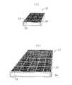
図1(1)は、本実施の形態のソーラーパネル20全体を示す斜視図である。ソーラーパネル20は、単位太陽電池モジュール21が複数連結されることによって、ソーラーパネル20全体が構成される。図1(2)に示すように、ソーラーパネル20から取出された単位太陽電池モジュール21は、同形状かつ同構成に規格化されて1つのユニットとして生産される。このユニットである単位太陽電池モジュール21を複数個組合せることによって所定のソーラーパネル20が形成される。
【0055】
図2(1)は、単位太陽電池モジュール21を示す斜視図である。単位太陽電池モジュール21は、複数の太陽電池セル22を接続するための複数の接続用配線23とそれらを固定する支持板24とを含んで構成される。
【0056】
各太陽電池セル22は、たとえば矩形状の結晶シリコン系太陽電池セルで支持板24に固定される。また太陽電池セル22に形成される電極は、接続用配線23によって他の太陽電池セルに接続される。支持板24はアルミニウムを主材料とするハニカム構造になっており、これによって単位太陽電池モジュール21は、軽量かつ高剛性に形成される。アルミニウム製ハニカム支持板24は、ソーラーパネル20の基板材料として実績が高い材料であり、比較的小さな単位太陽電池モジュール21の大きさに加工して用いた場合でも、その軽さと強度は宇宙用として適している。また太陽電池セル22の受光面側表面には図示しないカバーガラスが設けられている。
【0057】
単位太陽電池モジュール21は2枚以上の太陽電池セル22を接続用配線23を介して支持板24に固定したモジュール構造のユニットであって、たとえば図2(1)に示すように、約3cm×3cmの大きさの太陽電池セル22を3枚×3枚の計9枚並べて配線し、それらを厚さ約2.5cmの支持板に貼付けて、受光面側の面積が約100(10cm×10cm)cm2となる単位太陽電池モジュール21が構成される。このような単位太陽電池モジュール21を図1(1)に示すように8個×10個組合せることによって80cm×1mの宇宙用ソーラーパネルを組立てることができる。
【0058】
また図2(2)は、太陽電池セル22を6枚×5枚の計30枚並べた単位太陽電池モジュール21である。このように単位太陽電池モジュール21は、支持板24の大きさまたは太陽電池セル22の数を変更することによって、形状および発電能力をかえて設計することができる。
【0059】
単位太陽電池モジュール21は、ソーラーパネル20全体に搭載される太陽電池セル22に比べて、太陽電池セル数が比較的少なく、単位太陽電池モジュール21自体を作ることに対しては、比較的複雑な作業は要しない。また、ソーラーパネル20を、規格化された単位太陽電池モジュール21の組合せで構成すれば、同じもしくは類似形状の単位太陽電池モジュール21を何通りか用意することで、種々のソーラーパネル20の製造が可能となる。
【0060】
上記のように、単位太陽電池モジュール21の製造は、自動ラインによる大量生産が可能であるため、ソーラーパネル20の製造の容易化に寄与することができる。
【0061】
従来、太陽電池セル22を1つずつ溶接またはハンダ付けしていた作業が、この単位太陽電池モジュール21の導入によって、単位太陽電池モジュール21をソーラーパネル20に取付けるだけの作業となり、ソーラーパネル20の組立に要する作業工数が減少するうえ、作業が減少することにともなって、作業ミスも減少し、高い信頼性が要求される宇宙用ソーラーパネル20を能率よく製造することができる。
【0062】
また太陽電池セル22の破損に伴うソーラーパネル20の故障修理の場合、単位太陽電池モジュール21を交換するだけで作業を完了することができる。しかも、太陽電池セル22がいくつかまとまったものを単位として扱うので、単位太陽電池モジュール21を固定する取付け部の数や面積と、それにともなう全体の重量増加のコントロールが可能で、人工衛星などに使用される宇宙用としての強度と性能を維持しながらも、適度に作業性や生産性を改善することができる。
【0063】
また図2に図示しないが、逆バイアスに対して太陽電池セル22を保護する保護用ダイオード25(バイパスダイオード)が単位太陽電池モジュール21に搭載される。図3は、単位太陽電池モジュール21の一部を示す回路図の一例である。図3の場合は、各太陽電池セル22と並列に保護用ダイオード25がそれぞれ設けられる。保護用ダイオード25は、太陽電池セル22に大きな逆方向電圧が加わると電流の経路をバイパスするように取付けられる。
【0064】
図3に示すように、衛星の影などによって単位太陽電池モジュール21内の1つの太陽電池セル22aの発電能力が低下した場合、その太陽電池セル22aに並列に設けられた保護用ダイオード25aに電流がバイパスして流れ(図3でa方向に流れる)、逆バイアスから太陽電池セル22aを保護することができる。
【0065】
単位太陽電池モジュール21に保護用ダイオード25を搭載することによって、従来のソーラーパネルの製造方法のように、ソーラーパネル20上の太陽電池セルに保護用ダイオードを接続して貼付ける一連の作業を必要とせず、新たに特別な細工をしなくても、太陽電池セル22に逆バイアスがかかって破壊されるのを防ぐ機能を容易に備えることができる。
【0066】
図4は、枠体26全体を示す正面図である。ソーラーパネル20は、各単位太陽電池モジュール21が収納される収納空間27を備えた枠体26を含み、この枠体26の収納空間27に単位太陽電池モジュール21が嵌め込まれてソーラーパネル20が形成される。枠体26は、金属製またはCFRP(炭素繊維強化プラスチック:Carbon Fiber Reinforced Plastic)のような樹脂製の材料で形成される。
【0067】
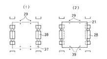
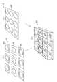
図5は、図4の枠体26のセクションS5を拡大して示す正面図であり、図5(1)は枠体26を示し、図5(2)は枠体26および枠体26に取付けられた1つの単位太陽電池モジュール21を示す。図5(1)に示すように枠体26は、収納空間27が設けられ、たとえば格子状に形成される。また枠体26には、各単位太陽電池モジュール21を電気的に連結するための接続導電路28が形成されるのが望ましい。さらに枠体26には、嵌め込まれた単位太陽電池モジュール21を固定するためのねじ孔29が形成される。ねじ孔29は、接続導電路28が形成される領域以外に配置されるのが望ましい。
【0068】
単位太陽電池モジュール21には、図5(2)のように、枠体26に嵌め込まれるために、収納空間27に対応する突出部が形成されるのが望ましい。また単位太陽電池モジュール21が枠体26に嵌め込まれたときに、枠体26のねじ孔29に対向する位置に単位太陽電池モジュール21のねじ孔39が形成されるのが望ましい。
【0069】
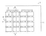
図6は、単位太陽電池モジュール21が嵌め込まれたソーラーパネル20全体の正面図を示し、図7は、図6のソーラーパネル20のセクションS7を拡大した正面図である。図6および図7に示すように、ソーラーパネル20には、単位太陽電池モジュール21がマトリックス状に配置され、互いの単位太陽電池モジュール21は、枠体26に設けられた接続導電路28を介して電気的に連結される。
【0070】
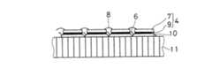
図8は、図7のソーラーパネル20の切断面線B−Bで切断した断面図である。図8に示すように、単位太陽電池モジュール21に形成された突出部30が収納空間27に嵌め込まれる。さらに嵌め込まれたときに、単位太陽電池モジュール21および枠体26のねじ孔29,39にねじ部材40を螺着して、単位太陽電池モジュール21を固定する。また、このねじ部材40を離脱させることによって、単位太陽電池モジュール21を枠体26から取外すことができる。
【0071】
単位太陽電池モジュール21は、枠体26に取付けられることによって、枠体26の接続導電路28が、単位太陽電池モジュール21の接続用配線23に当接し、電気的にも接続される。
【0072】
図9(1)は、カバーガラス33を有する単位太陽電池モジュール21の断面図であり、図9(2)は、図9(1)の正面図である。単位太陽電池モジュール21には、太陽電池セル22の受光面側表面と密着するようにカバーガラス33が設けられる。カバーガラス33は複数設けられ、各カバーガラス33は、各太陽電池セル33と対応するようにそれぞれ取付けられる。カバーガラス33が設けられることによって、太陽電池セル22は低エネルギーの宇宙線などから保護される。また各カバーガラスを電気的に接続するように透光性の導電性層34などが各カバーガラス受光面の全体にかぶせられる。
【0073】
図10(1)は、図9とは、異なる他のカバーガラス33aを有する単位太陽電池モジュール21の断面図であり、図10(2)は、図10(1)の正面図である。単位太陽電池モジュール21には、太陽電池セル22の受光面側表面と密着するように一枚のカバーガラス33aが設けられる。カバーガラス33aが設けられることによって、太陽電池セル22は低エネルギーの宇宙線などから保護される。またカバーガラス33aの表面には、透光性の導電性の導電性層34aなどがコーティングされている。
【0074】
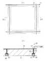
図11(1),(2)は支持部35が設けられる枠体26を示し、図12は図11(2)の切断面線C−Cで切断した断面図である。さらに枠体26は、単位太陽電池モジュール21が枠体26に嵌め込まれたときに、単位太陽電池モジュール21の四方の側面と当接する領域に支持部35が設けられる。支持部35は、単位太陽電池モジュール21の受光側の面に接する辺を含む領域を宇宙機の衛星グランドに接続する、導電性の材料で形成されるグランド導電路41が形成される。
【0075】
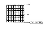
図13は、枠体26を用いて構成されるソーラーパネル20全体の正面図を示し、図14(1)は、図13のセクションS14を拡大して示し、図14(1)の切断面線D−Dで切断した断面図を図14(2)に示す。ソーラーパネル20として組上げられた状態で支持部35のグランド導電路41が電気的にグランドに接続されることで、各単位太陽電池モジュール21受光側表面を宇宙機のグランドに落とすことができ、太陽電池セル22の表面を保護しているカバーガラス33表面を、荷電粒子の飛来等によるチャージアップから解放することができる。この方法によって、パネル化した後に太陽電池セル22、1つ1つの表面にグランドに接続させる配線を取付ける作業を行うことを省略することができる。
【0076】
またソーラーパネル20の物理的な強度を上げるために、相互に接続された複数個の単位太陽電池モジュール21に、樹脂膜で裏打ちを行う。この枠体26と単位太陽電池モジュール21とを用いた宇宙用ソーラーパネル20の構造は、従来よりもパネルの強度が劣る可能性があるが、簡単に切り取ることができ、重量も軽い有機樹脂膜などを補強膜として用いることで、この問題も解消される。
【0077】
単位太陽電池モジュール21を連結する他のソーラーパネル20aの実施形態として、枠体26にかえて図15に示すような、基板36を用いてもよい。基板36は、金属製もしくはCFRPのような樹脂製の材料によって構成される。また基板36を用いた実施の形態は、前述の実施の形態と類似しており、同様の構成部分は、同一の参照符号を付し、説明を省略する。
【0078】
ソーラーパネル20aは、図15に示すように、単位太陽電池モジュール21を配置位置37(図15において2点鎖線で囲まれた領域)に並べて連結することができる基板36を有し、単位太陽電池モジュール21を基板36上に配置してパネル全体が構成される。
【0079】
図16は、図15の基板36をセクションS16を拡大して示す図であり、図16(1)に示すように、基板36は、単位太陽電池モジュール21を並べるためのねじ孔29があけられており、単位太陽電池モジュール21が当接する面には、各単位太陽電池モジュール21を電気的に接続するための接続導電路28が設けられる。
【0080】
図16(2)は、基板36に1つの単位太陽電池モジュール21が配置された時の正面図である。単位太陽電池モジュール21は、基板36上の配置位置37に配置されたときに、基板36のねじ孔29に対向する位置にねじ孔39が形成される。単位太陽電池モジュール21は、所定の配置位置37に配置される。
【0081】
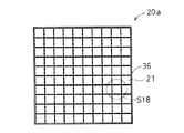
図17は単位太陽電池モジュール21が配置されたソーラーパネル20a全体の正面図を示し、図18は図17のソーラーパネル20aのセクションS18を拡大して示す。図17および図18に示すように、ソーラーパネル20aは、単位太陽電池モジュール21がマトリックス状に配置され、互いの単位太陽電池モジュール21は、基板36に設けられた接続導電路28を介して電気的に連結される。
【0082】
図19は、図18のソーラーパネル20aの切断面線E−Eで切断した断面図である。図18に示すように、単位太陽電池モジュール21が基板36上に並んで配置される。前述の枠体26と同様に、ねじ部材40によって基板36に着脱可能に固定される。
【0083】
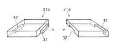
さらに他の実施の形態の単位太陽電池モジュール21aの斜視図を図20、図21に示す。この他の実施の形態の単位太陽電池モジュール21aにおいて、前述と同様の構成部分は、同一の参照符号を付し、説明を省略する。
【0084】
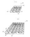
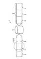
単位太陽電池モジュール21aは、相互に直接機械的に連結することができる構造を有し、単位太陽電池モジュール21a同士を直接機械的に連結することによって、パネル全体を構成する。具体的には、単位太陽電池モジュール21aの一側部に設けられる凸部31と他側部に設けられる凹部32とを有する。
【0085】
図21に示すように、単位太陽電池モジュール21aは、凸部31と凹部32とを相互につなぎ合わせることができ、複数の単位太陽電池モジュール21aを連結することによって、接続方向を間違えずに、容易にパネル全体を構成することができる。単位太陽電池モジュール21aは、規格化された構造を採用することによって、電極の極性とその構造に規則性を持たせることができ、またパネルに組立てる場合においても、単位太陽電池モジュール21a同士が接続されるのは、そのほとんどが直列接続、つまりプラス電極とマイナス電極が接続される場合ばかりであるので、この方法はパネル製造の容易化に効果的である。
【0086】
また複数連結された単位太陽電池モジュール21aが収納される収納空間を備えた枠体に、連結された単位太陽電池モジュール21aが嵌め込まれることによってパネル全体を構成してもよい。これによって、単位太陽電池モジュール同士が連結され、さらに収納空間に収納されるので、単位太陽電池モジュール21aをより確実に固定し、ソーラーパネルの剛性をさらに向上させることができる。
【0087】
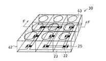
さらに他の実施の形態として前述の単位太陽電池モジュール21,21aに太陽電池セルに光を集めるための集光レンズ43を用いた実施の他の形態である集光型単位太陽電池モジュール30の斜視図を図22に示す。集光型単位太陽電池モジュール30は、上述の単位太陽電池モジュール21,21aと類似しており、同様の構成については、同一の符号で示し、説明を省略する。
【0088】
集光型単位太陽電池モジュール30は、光を集光する集光レンズ43と複数の太陽電池セル22と各太陽電池セル22を接続するための複数の接続用配線23とそれらを支持するフレーム42とを含んで構成される。集光レンズ43は、入射光がそれぞれの太陽電池セル22の位置に収束するように設計されている。
【0089】
各太陽電池セル22は、フレーム42に固定される。また太陽電池セル22に形成される電極は接続用配線23によって他の太陽電池セル22と結合される。フレーム42によって集光レンズ43を支えることによって、軽量化した集光型ソーラーパネルを形成することができる。
【0090】
集光型単位太陽電池モジュール30は2枚以上の太陽電池セル22を接続用配線23を介してフレーム42に固定したモジュール構造のユニットであって、たとえば図22(1)に示すように、太陽電池セル22を3枚×3枚の計9枚並べた集光型単位太陽電池モジュール30が構成される。この集光型単位太陽電池モジュール30を図1に示すように8個×10個組合せることによって集光型の宇宙用ソーラーパネルを組立てることができる。
【0091】
また図22(2)は、太陽電池セル22を6枚×5枚の計30枚並べた集光型単位太陽電池モジュール30である。このように集光型単位太陽電池モジュール30は、太陽電池セル22の数、フレームの形状または集光レンズによる光量などを変更することによって、形状および発電能力をかえて設計することができる。
【0092】
前述の単位太陽電池モジュール21,21aと同様に、集光型単位太陽電池モジュール30自体を作ることに対しては、比較的複雑な作業は要せず、規格化された集光型単位太陽電池モジュール30の組合せで構成すれば、同じもしくは集光型類似形状の単位太陽電池モジュール30を何通りか用意することで、種々の集光型ソーラーパネル製造が可能となる。
【0093】
従来の集光ソーラーパネルはレンズの設置に伴って部品点数も増え、また集光レンズ43と太陽電池セル22の調整を正確に行いながら全体を組立てる必要があり、パネル製造が難しかったが、本発明による集光型単位太陽電池モジュール30を用いれば、従来に比べて容易にパネル化が可能となる。
【0094】
図23に示すように、集光型単位太陽電池モジュール30は、前述の単位太陽電池モジュールと同様に太陽電池セル22を保護するために保護用ダイオード25が設けられる。これによって一部の太陽電池セル22が発電能力が低下したとき、電流の経路をバイパスして、太陽電池セル22を保護することができる。
【0095】
図24は、図23の集光型単位太陽電池モジュール30の切断面線F−Fで切断したときの断面図を示す。集光レンズ43によって集光される光が当たる領域44に太陽電池セル22が配置され、集光された光が当たらない領域45に、接続用配線23および保護用ダイオード25が配置される。これによって、光が当たらない領域45に配置された部材、たとえば保護用ダイオード25または接続用配線23などは、光による劣化を防止することができる。
【0096】
集光レンズ43は、たとえば板状のレンズプレート46によって形成されており、図25(1)に示すように、1枚のレンズプレート46に対して1つの焦点を有し、太陽電池セル22に対応する数だけのレンズプレート46(図25では9枚)を組合せ、各レンズプレート46の焦点に対応した位置に太陽電池セル22を配置することで図25(3)に示す集光型単位太陽電池モジュール30を構成することができる。
【0097】
また図25(2)に示すように、集光レンズ43´は、1枚のレンズプレート46´に対して連続していない複数の焦点を持った構造を有し、その焦点に対応した位置に太陽電池セル22を配置することによっても図25(3)に示す集光型単位太陽電池モジュール30を構成することができる。これによって、集光型単位太陽電池モジュール30の部品点数を少なくすることができる。
【0098】
このような集光型単位太陽電池モジュール30は、前述の単位太陽電池モジュール21と同様に、マトリックス状に連結されることによって、集光型のソーラーパネルを形成する。集光型単位太陽電池モジュール30を並べる手段は、たとえば図4〜14に示すように集光型単位太陽電池モジュール30が収納される収納空間27を有する枠体26の収納空間に着脱可能に収納されることによって、集光型ソーラーパネルを形成することができる。
【0099】
また、集光レンズ43の受光側表面には、宇宙機のグランドに接続される透光性の導電性層34がコーティングされており、導電性層34がグランド導電路41と電気的に接続されることで、集光レンズ43,43´表面がチャージアップすることを防止することができる。
【0100】
また図15〜19に示すように、基板36に配置することによっても、集光型単位太陽電池モジュール30を並べて集光型ソーラーパネルを形成することができる。またさらに図26に示すように、集光型単位太陽電池モジュールの一側部に凸部31を他側部に凹部32を設け、互いに結合することによって機械的に連結することができる集光型単位太陽電池モジュール30aによって、集光型ソーラーパネルを形成してもよい。
【0101】
上述に記載する宇宙用ソーラーパネルにおいて太陽電池セル22の一部が破損した場合は、破損した太陽電池セル22が取付けられた単位太陽電池モジュールまたは集光型単位太陽電池モジュールを取外して、交換することによって、ソーラーパネルの修理または調整を行う。単位太陽電池モジュールまたは集光型単位太陽電池モジュールが、着脱可能に取付けられ、さらに機械的に分離/接続することによって、電気的に分離/接続することができるので、このようなモジュールを交換する方法は、ソーラーパネルの修理または調整を非常に容易に行うことができる。
【0102】
また上述のこのような実施の形態は、1つの例示に過ぎず発明の範囲内において構成を変更してもよい。たとえば上述した実施形態では、人工衛星に用いられるソーラーパネルとしたが、本発明はこれに限らず、宇宙空間で使用されるすべての用途に適用することができる。
【0103】
【発明の効果】
以上のように本発明によれば、規格化された単位太陽電池モジュールを組合せて構成することによって大きさや発電能力の異なるソーラーパネルを容易に形成することができる。また規格化された単位太陽電池モジュールを共通して様々なソーラーパネルに利用することで、単位太陽電池モジュールの自動ライン製造による大量生産が可能である。
【0104】
またソーラーパネルは、複数の単位太陽電池モジュールが枠体の各収容空間にそれぞれ嵌り込むことによって、互いの単位太陽電池モジュールを機械的に連結することによって電気的にも接続することができる。これによってパネルの組立て作業に要する作業工程が減少するうえに、作業の減少にともなって作業ミスも減少し、信頼性の高い宇宙用ソーラーパネルを能率よく生産することができる。
【0105】
また太陽電池セルが破損したとき、破損した単位太陽電池モジュールだけを容易に取外して交換することができるので、たとえば宇宙空間におけるソーラーパネルの修復作業の難易度を低下させることができる。さらにソーラーパネル製造中または、その後の修理時作業の能率を向上させることができる。さらに複数連結される単位太陽電池モジュールが、枠体の収容空間に嵌め込まれることによって振動することが抑制され、ソーラーパネル自体の剛性を向上することができる。したがって宇宙空間への搬送時に生じる振動および加速度に対してもソーラーパネルが破損する可能性を低下させることができる。また枠体に単位太陽電池モジュールを嵌め込むことで、単位太陽電池モジュールを位置決めする作業が容易になり、さらに容易にソーラーパネルを組立てることができる。
また本発明によれば、単位太陽電池モジュールの受光面側をグランドに接続することによって、ソーラーパネル表面がチャージアップするのを防ぐことができる。
また本発明によれば、規格化された単位太陽電池モジュールを組合せて構成することによって大きさや発電能力の異なるソーラーパネルを容易に形成することができる。また規格化された単位太陽電池モジュールを共通して様々なソーラーパネルに利用することで、単位太陽電池モジュールの自動ライン製造による大量生産が可能である。
またソーラーパネルは、複数の単位太陽電池モジュールが基板にそれぞれ固定されることによって、互いの単位太陽電池モジュールを機械的に連結することによって電気的にも接続することができる。これによってパネルの組立て作業に要する作業工程が減少するうえに、作業の減少にともなって作業ミスも減少し、信頼性の高い宇宙用ソーラーパネルを能率よく生産することができる。
また太陽電池セルが破損したとき、破損した単位太陽電池モジュールだけを容易に取外して交換することができるので、たとえば宇宙空間におけるソーラーパネルの修復作業の難易度を低下させることができる。さらにソーラーパネル製造中または、その後の修理時作業の能率を向上させることができる。さらに単位太陽電池モジュールが、基板上の配置位置に接続されることで、単位太陽電池モジュールを基板によって補強し、太陽電池セルが破損することを防止することができる。
また本発明によれば、単位太陽電池モジュール同士が直接機械的に着脱可能な構造を有する単位太陽電池モジュールが、相互に直接機械的に連結されることによって、パネル全体が構成される。これによって単位太陽電池モジュールを連結するための下地を不要として、パネル全体を構成することができる。
また本発明によれば、単位太陽電池モジュール同士を直接機械的に複数連結することによって、ソーラーパネルを容易に組立てることができ、パネル全体を構成することができる。さらに枠体の収納空間に相互に連結された単位太陽電池モジュールが嵌め込まれることによって、単位太陽電池モジュールが枠体に固定され、ソーラーパネル全体の剛性を向上させることができる。
また本発明によれば、単位太陽電池モジュールの一側部に凸部を、他側部に凹部を設けることによって直接機械的に複数連結することができる。したがって単位太陽電池モジュールの配置方向を間違えて連結するおそれがなく、宇宙空間などの複雑な作業が行いにくい場所においても容易に連結することができる。
【0106】
また本発明によれば、単位太陽電池モジュールに保護用ダイオードを設けることによって、逆バイアスによる太陽電池セルの破損を防止することができる。また故障した太陽電池セルの被害を最小限にすることができる。したがって単位太陽電池モジュールの信頼性を向上することができ、宇宙空間のような交換または修理が行いにくい場所に使用することができる。
【0107】
また本発明によれば、太陽電池セルが支持板に固定されることによって、単位太陽電池モジュールの剛性を向上することができる。したがって、宇宙空間への搬送時にかかる加速および振動によってソーラーパネルが破損する可能性が減少する。さらに支持板は、ハニカム構造のアルミニウム材料で形成されることによって、単位太陽電池モジュールを軽量かつ充分な強度を保つことができる。
【0113】
また本発明によれば、集光レンズで太陽光を絞ることによって、太陽電池の大きさを小さくして、半導体の使用量を抑え、コストを下げることができる。また単位太陽電池モジュールは、集光レンズの配置が設定されているので、ソーラーパネル組立て時に集光レンズと太陽電池との位置調整を行う必要がなく、容易に組立てることができる。
【0114】
また本発明によれば、フレームによって集光レンズを充分な強度で固定することができる。
【0115】
また本発明によれば、集光レンズが複数の焦点を持つので、単位太陽電池モジュールに配置される太陽電池セル毎に集光レンズを設ける必要がなく、単位太陽電池モジュールの部品数を少なくすることができる。単位太陽電池モジュールを作成することが容易になる。
【0116】
また本発明によれば、接続用配線および保護用ダイオードは、光の集光されない領域に配置されるので、光による劣化が防止され、高寿命化することができる。これによって、ソーラーパネルの信頼性が向上し、宇宙空間のような交換または修理が行いにくい場所に使用することができる。
【0117】
また本発明によれば、導電性薄膜がグランドに接続されるので、ソーラーパネル表面がチャージアップするのを防ぐことができ、チャージアップによるトラブルを防止することができる。
【0118】
単位太陽電池モジュールは、相互に着脱可能にソーラーパネルに連結されるので、故障した太陽電池セルを有する単位太陽電池モジュールを取外し交換することによって、ソーラーパネルのメンテナンスを行うことができる。
【0119】
これによって、従来よりも少ない作業量で太陽電池セルの交換をともなう修理またはメンテナンスなどの作業も容易に行え、従来では難しいと思われていた宇宙空間でのメンテナンスにも適応することができる。
【図面の簡単な説明】
【図1】本実施の形態の宇宙用ソーラーパネル20である。
【図2】単位太陽電池モジュール21を示す斜視図である。
【図3】単位太陽電池モジュール21の一部を示す回路図の一例である。
【図4】枠体26を示す正面図である。
【図5】図4の枠体26のセクションS5を拡大して示す正面図である。
【図6】枠体26を有するソーラーパネル20の正面図を示す正面図である。
【図7】図6のソーラーパネルのセクションS7を拡大して示す正面図である。
【図8】図7のソーラーパネル20の切断面線B−Bで切断した断面図である。
【図9】カバーガラス33を有する単位太陽電池モジュール21を示す図である。
【図10】カバーガラス33aを有する単位太陽電池モジュール21を示す図である。
【図11】支持部35が形成される枠体26を示す図である。
【図12】図11の枠体26の切断面線C−Cで切断した断面図である。
【図13】枠体26を有するソーラーパネル20を示す正面図である。
【図14】図13のソーラーパネル20を拡大して示す図である。
【図15】基板36を示す正面図である。
【図16】図15の基板36のセクションS16を拡大して示す図である。
【図17】基板36を用いたソーラーパネル20aを示す正面図である。
【図18】図17のソーラーパネル20aのセクションS18を拡大して示す図である。
【図19】図18のソーラーパネル20aの切断面線E−Eで切断した断面図である。
【図20】他の実施の形態の単位太陽電池モジュール21aを示すの斜視図である。
【図21】単位太陽電池モジュール21aを示す斜視図である。
【図22】集光型単位太陽電池モジュール30を示す斜視図である。
【図23】集光型単位太陽電池モジュール30を示す斜視図である。
【図24】図23の集光型単位太陽電池モジュール30の切断面線F−Fで切断した断面図である。
【図25】集光型単位太陽電池モジュール30のレンズプレート46を示す斜視図である。
【図26】集光型単位太陽電池モジュール30aを示す斜視図である。
【図27】従来の人工衛星1を示す斜視図である。
【図28】図27のソーラーパネル3のセクションS28を拡大して示す図である。
【図29】図28のソーラーパネル3のセクションS29を拡大して示す図である。
【図30】図29のソーラーパネル3を切断面線A−Aで切断した断面図である。
【符号の説明】
20,20a ソーラーパネル
21,21a 単位太陽電池モジュール
22 太陽電池セル
23 接続用配線
24 支持板
25 保護用ダイオード
26 枠体
27 収納空間
28 接続導電路
30 集光型単位太陽電池モジュール
33,33a カバーガラス
34,34a 導電性層
36 基板
40 ねじ部材
41 グランド導電路
42 フレーム
43,43´ 集光レンズ
46,46´ レンズプレート[0001]
[Technical field to which the invention belongs]
The present invention relates to a solar panel for space that is mounted on, for example, an artificial satellite and a space station and used in outer space.
[0002]
[Prior art]
FIG. 27 is a schematic diagram showing a conventional
[0003]
The
[0004]
FIG. 28 is an enlarged front view showing a section S28 (solar panel part) of the
[0005]
30 is a cross-sectional view taken along the cutting plane line AA of FIG. The
[0006]
Such a conventional space
[0007]
Further, the cover glass provided in close contact with the light receiving surface side of each solar battery cell is coated with a conductive film and bonded by a conductive connecting wire that electrically connects the cover glasses.
[0008]
At this time, an irreversible connection method such as welding or soldering is used as an electrical connection method between the solar battery cell and the conductive connection fitting and an electrical connection method between the cover glass and the conductive connection wire. . In addition, an irreversible connection method using an adhesive or the like is also used as a means for arranging the solar battery cell and the conductive connecting metal fitting on the support plate.
[0009]
By irreversibly connecting the members constituting the solar panel in this way, it is possible to ensure high reliability against vibrations generated when the artificial satellite is transported to space and the environment in space.
[0010]
[Problem to be Solved by the Invention]
In such a conventional technique, in manufacturing a solar panel for space, an operation of bonding all of thousands to tens of thousands of solar cells constituting a solar panel to a support plate with an adhesive is performed. In addition, in all of the wiring for electrically connecting the solar cells and the wiring for electrically connecting the cover glasses that are in close contact with the light receiving surface side of the solar cells, the work for electrical connection by welding or soldering I do.
[0011]
Conventional space solar panels are large and often have different shapes depending on the purpose of use, and it is difficult to manufacture solar panels on an automated production line. Therefore, manufacturing a solar panel for space has a complicated work process and spends a lot of work time.
[0012]
In addition, most of the members constituting conventional solar panels for space use are joined in an irreversible manner, causing problems such as damage to the solar cells during the manufacturing process or assembly process. When it was necessary to repair a solar panel that accompanied the replacement, the labor involved in the replacement was also very complicated.
[0013]
In the replacement operation, first, the metal wiring (interconnector) electrically connected between the solar cells by welding or the like is cut to electrically separate the solar cells from the solar panel. Next, the adhesive on the back side of the solar battery cell is cut, and the solar battery cell is peeled off from the solar panel. A new solar cell, which is slightly smaller than the space left on the stripped mark, is pasted with an adhesive, and wiring is connected again by welding. The solar panel was repaired by performing such a complicated work process.
[0014]
This series of operations is performed every time when a defect occurs in all of the large number of solar cells mounted in the entire area of the solar panel, and the amount of work is large depending on the degree of repair.
[0015]
In addition, in recent years, with the increase in size of artificial satellites, solar cells with high photoelectric conversion efficiency have been demanded, and solar cell materials are also changed from conventional silicon (Si) to gallium-arsenide (GaAs) III- It has changed to a group V semiconductor. In general, III-V group semiconductor crystals are brittle and easily cracked. Solar cells using these materials have a higher probability of cracking or chipping than Si solar cells. Also in the conventional solar panel manufacturing method, the frequency of cell replacement or repair accompanying the cracking of the solar cell tends to increase further due to the change of the solar cell material to the III-V group semiconductor.
[0016]
Conventionally, the above replacement work has been performed at the stage of solar panel manufacture on the ground and installation on a satellite. However, due to recent advances in space technology, it has become an environment where humans stay and work in outer space for a relatively long period of time, such as the recovery of artificial satellites by manned space shuttles and practical applications of manned space stations. The possibility of repairing in outer space, which was physically difficult in the past, has also increased. However, repairing a solar panel by the conventional method requires a complicated and large amount of work as described above, which is virtually impossible.
[0017]
The present invention has been made in view of the present situation. Therefore, the object of the present invention is to easily manufacture a solar panel for space use in a short time and to easily replace or repair a solar cell in a short time. Space solar panels that can be made and theirRepairIs to provide a method.
[0018]
[Means for Solving the Problems]
The present invention(A)A unit solar cell module including a plurality of solar cells and connection wiring for connecting the solar cells; and
(B) A frame that mechanically fixes the plurality of unit solar cell modules in a detachable manner,
(B1) While a plurality of housing spaces into which the protrusions formed in the unit solar cell module are respectively fitted are formed,
(B2) A connection conductive path is formed in contact with the connection wiring of the unit solar cell module fitted in the accommodation space to electrically connect the plurality of unit solar cell modules respectively fitted in the accommodation space. Including frameThis is a solar panel for space.
[0019]
According to the present invention, a space solar panel can be formed by combining unit solar cell modules to which a plurality of solar cells are attached. Therefore, by changing the combination of unit solar cell modules, it is possible to easily form solar panels having different power generation or shapes. Since the standardized unit solar cell module can be mass-produced by automation, the solar panel can be manufactured easily and in a short time.
[0020]
Since the unit solar cell modules are electrically wired, they can be electrically connected by mechanically connecting the unit solar cell modules to each other. Therefore, the work process for electrically connecting the unit solar cell modules is not required, and the assembly work and repair work of the solar panel can be omitted, thereby shortening the work time.
Specifically, when the unit solar cell module is fitted into the housing space of the frame, the connection wiring of the unit solar cell module and the connection conductive path formed in the frame abut, and the unit solar cell module The frame is electrically connected. Further, in a state where the plurality of unit solar cell modules are respectively fitted in the housing spaces of the frame, the connection conductive paths of the frame electrically connect the connection wirings of the unit solar cell modules. In this manner, the unit solar cell modules can be electrically connected by mechanically connecting the unit solar cell modules.
In addition, the unit solar cell module is fixed to the frame body by being fitted in the housing space of the frame body, and the vibration of the unit solar cell module can be suppressed and the rigidity of the entire solar panel can be improved. Moreover, it becomes easy to position the arrangement position of the unit solar cell module, and the solar panel can be easily assembled without making the arrangement position wrong. The unit solar cell module is detachably attached to the frame. Therefore, for example, only the damaged unit solar cell module can be easily removed, and the solar panel can be easily repaired or adjusted.
[0021]
The present invention also providesIn the unit solar cell module, a conductive layer is formed on the light receiving surface side surface of the solar cell,
The frame body has a ground conductive path that contacts the conductive layer of the unit solar cell module fitted in the accommodation space and electrically connects the conductive layer and the ground of the spacecraft.It is characterized by that.
According to the present invention, when the unit solar cell module is fitted into the housing space of the frame body, a conductive layer formed on the light receiving surface side surface of the solar battery cell, and a ground conductive path formed on the frame body, Are electrically connected. Therefore, the surface on the light receiving surface side of the solar battery cell is electrically connected to the ground of the spacecraft through the ground conductive path. By fitting the unit solar cell module into the housing space of the frame body in this way, the light receiving side surface of the unit solar cell module is connected to the ground by the ground conductive path, and the light receiving side of the unit solar cell module by the cosmic rays is connected. It is possible to suppress the surface from being charged up.
The present invention also includes (a) a unit solar cell module configured to include a plurality of solar cells and a connection wiring for connecting the solar cells;
(B) a substrate for mechanically fixing a plurality of the unit solar cell modules in a detachable manner,
(B1) In a state where the plurality of unit solar cell modules are arranged and fixed, a connection conductive path that contacts the connection wiring of the unit solar cell modules and electrically connects the plurality of unit solar cell modules that are fixed respectively. Including a substrate to be formedIt is characterized byRuIt is a solar panel for the air.
According to the present invention, a space solar panel can be formed by combining unit solar cell modules to which a plurality of solar cells are attached. Therefore, by changing the combination of unit solar cell modules, it is possible to easily form solar panels having different power generation or shapes. Since the standardized unit solar cell module can be mass-produced by automation, the solar panel can be manufactured easily and in a short time.
Further, since the unit solar cell modules are electrically wired, they can be electrically connected by mechanically connecting the unit solar cell modules to each other. Therefore, the work process for electrically connecting the unit solar cell modules is not required, and the assembly work and repair work of the solar panel can be omitted, thereby shortening the work time.
Specifically, when the unit solar cell module is fixed to the substrate, the connection wiring of the unit solar cell module comes into contact with the connection conductive path formed on the substrate, and the unit solar cell module and the substrate are electrically connected. Connected. Further, in a state where the plurality of unit solar cell modules are respectively fixed to the substrate, the connection conductive path of the substrate electrically connects the connection wirings of the unit solar cell modules. In this manner, the unit solar cell modules can be electrically connected by mechanically connecting the unit solar cell modules.
Moreover, the unit solar cell module is connected to the arrangement position on the substrate, thereby eliminating the trouble of positioning the arrangement position. Moreover, it can prevent further that a photovoltaic cell is damaged by reinforcing the photovoltaic cell which is easy to damage with a board | substrate. The unit solar cell module is detachably attached to the substrate. Therefore, for example, only the damaged unit solar cell module can be easily removed, and the solar panel can be easily repaired or adjusted.
[0022]
Further, the present invention is a unit solar cell module including a plurality of solar cells and connection wiring for connecting the solar cells, wherein the unit solar cell modules are directly and detachably attached to each other. The solar cell panel for space is characterized in that unit solar cell modules having a possible structure are directly mechanically connected to each other to constitute the entire panel.
According to the present invention, a space solar panel can be formed by combining unit solar cell modules to which a plurality of solar cells are attached. Therefore, by changing the combination of unit solar cell modules, it is possible to easily form solar panels having different power generation or shapes. Since the standardized unit solar cell module can be mass-produced by automation, the solar panel can be manufactured easily and in a short time.
Further, by directly mechanically connecting a plurality of unit solar cell modules, it is possible to easily assemble a solar panel, and it is possible to configure the entire panel without using a ground for connecting the unit solar cell modules. The unit solar cell modules connected to each other are detachably attached to each other. Therefore, for example, only the damaged unit solar cell module can be easily removed, and the solar panel can be easily repaired or adjusted.
The present invention is also a unit solar cell module comprising (a) a plurality of solar cells and connection wiring for connecting the solar cells, and the unit solar cell modules are directly machined. A unit solar cell module having a detachable structure,
(B) a frame body in which a housing space in which a plurality of unit solar cell modules to be coupled are housed is formed;
(C) The solar panel for space use, wherein the plurality of unit solar cell modules connected to each other are fitted into a housing space formed in the frame body, whereby the entire panel is configured.
According to the present invention, a space solar panel can be formed by combining unit solar cell modules to which a plurality of solar cells are attached. Therefore, by changing the combination of unit solar cell modules, it is possible to easily form solar panels having different power generation or shapes. Since the standardized unit solar cell module can be mass-produced by automation, the solar panel can be manufactured easily and in a short time.
In addition, by directly mechanically connecting a plurality of unit solar cell modules, the solar panel can be easily assembled and the entire panel can be configured. The unit solar cell modules connected to each other are detachably attached to each other. Therefore, for example, only the damaged unit solar cell module can be easily removed, and the solar panel can be easily repaired or adjusted.
Further, by fitting a plurality of unit solar cell modules connected to the storage space of the frame, a plurality of unit solar cell modules to be connected are fixed to the frame, and the rigidity of the entire solar panel can be improved.
In the present invention, the mechanical structure in which the unit solar cell modules are mechanically connected to each other includes a convex portion provided on one side portion of the unit solar cell module and a concave portion provided on the other side portion. It is characterized by being.
According to the present invention, an arbitrary number of unit solar cell modules can be easily and continuously connected by engaging a convex portion of one unit solar cell module and a concave portion of another unit solar cell module. it can. Moreover, since a recessed part and a convex part engage, there is no possibility that the unit solar cell module may be connected in the wrong direction.
[0023]
The present invention is also characterized in that a protective diode for protecting the solar cell against reverse bias is mounted on the unit solar cell module.
[0024]
According to the present invention, the unit solar cell module has a protective diode. Therefore, when a solar cell is hidden in the shadow of the satellite body and the solar cell stops generating power, or when the solar cell becomes unable to generate power due to damage or contamination of the cell itself, the current is bypassed through the diode to generate power. It is possible to minimize the damage to the solar panel due to the reduced performance of the solar cells.
[0025]
In the present invention, the unit solar cell module has a honeycomb structure supporting plate made of aluminum as a main material, and solar cells are fixed to the supporting plate.
[0026]
According to the present invention, since the unit solar battery module has the support plate, the strength can be improved by fixing the solar battery cell to the support plate. Furthermore, the support plate is formed of an aluminum material having a honeycomb structure, so that the unit solar cell module can be kept lightweight and sufficiently strong.
[0041]
In the present invention, the unit solar cell module includes a condensing lens for collecting light in the solar cell.
[0042]
According to the present invention, the solar cell can receive the collected light by the condensing lens, so that the light energy can be more effectively converted into electric energy. Therefore, the area of the solar battery cell can be reduced compared to the light receiving area of the solar panel itself. Thereby, the solar panel can be reduced in size and weight, and the amount of expensive semiconductor cells used can be suppressed.
[0043]
In the unit solar battery module, the arrangement of the condensing lens and the solar battery cell is adjusted, and it is not necessary to adjust the position of the condensing lens and the solar battery cell when the solar panel is assembled.
[0044]
In the present invention, the unit solar cell module includes a frame that supports the condenser lens, the solar cell, and the connection wiring.
[0045]
According to the present invention, the condenser lens is fixed with sufficient strength by the frame, and the solar-The panel can be reduced in weight.
[0046]
According to the present invention, the condensing lens has a structure having a plurality of non-continuous focal points with respect to a single lens plate, and solar cells are arranged at positions corresponding to the focal points. It is characterized by that.
[0047]
According to the present invention, since the condensing lens has a plurality of focal points, it is not necessary to provide a condensing lens for each solar cell arranged in the unit solar cell module. For example, nine solar cells are provided in the unit solar cell module. When the cell is arranged, it is only necessary to attach one lens plate having nine focal points, and the number of parts of the unit solar cell module is reduced as compared with the case where nine lens plates having one focal point are attached. can do.
[0048]
Further, the invention is characterized in that the connection wiring and the protection diode are arranged in a region where the light condensed by the condenser lens does not hit.
[0049]
According to the present invention, since the connection wiring and the protection diode are arranged in a region where no light is applied, deterioration due to light can be prevented and the life can be extended.
[0050]
In the invention, it is preferable that the surface of the condenser lens is coated with a translucent conductive thin film connected to the ground of the spacecraft.
[0051]
According to the present invention, the conductive thin film can suppress the surface of the condenser lens from being charged up by cosmic rays.
[0052]
The present invention also providesA repair method for repairing or adjusting the space solar panel, and when a solar cell is damaged in the space solar panel, only the unit solar cell module including the damaged solar cell is removed and replaced. The solar panel repair method for space is characterized by performing repair or adjustment of the solar panel.
[0053]
According to the present invention, the unit solar cell module isMutualSince it is connected so that attachment or detachment is possible, the solar panel repair work can be facilitated and the working time can be shortened by removing and replacing the unit solar battery module having the failed solar battery cell.
[0054]
DETAILED DESCRIPTION OF THE INVENTION
FIG. 1A is a perspective view showing the entire
[0055]
FIG. 2A is a perspective view showing the unit
[0056]
Each
[0057]
The unit
[0058]
FIG. 2B shows a unit
[0059]
The unit
[0060]
As described above, the production of the unit
[0061]
Conventionally, the operation of welding or soldering the
[0062]
Further, in the case of failure repair of the
[0063]
Although not shown in FIG. 2, a protection diode 25 (bypass diode) that protects the
[0064]
As shown in FIG. 3, when the power generation capability of one
[0065]
By mounting the
[0066]
FIG. 4 is a front view showing the
[0067]
5 is an enlarged front view showing the section S5 of the
[0068]
As shown in FIG. 5B, the unit
[0069]
6 is a front view of the entire
[0070]
FIG. 8 is a cross-sectional view of the
[0071]
By attaching the unit
[0072]
FIG. 9 (1) is a cross-sectional view of the unit
[0073]
FIG. 10 (1) is a cross-sectional view of the unit
[0074]
11 (1) and 11 (2) show the
[0075]
FIG. 13 is a front view of the entire
[0076]
Further, in order to increase the physical strength of the
[0077]
As another embodiment of the
[0078]
As shown in FIG. 15, the
[0079]
FIG. 16 is an enlarged view of the section S16 of the
[0080]
FIG. 16 (2) is a front view when one unit
[0081]
FIG. 17 shows a front view of the entire
[0082]
FIG. 19 is a cross-sectional view of the
[0083]
Furthermore, the perspective view of the unit
[0084]
The unit
[0085]
As shown in FIG. 21, the unit
[0086]
Moreover, you may comprise the whole panel by fitting the unit
[0087]
Further, as another embodiment, a perspective view of a concentrating unit
[0088]
The concentrating unit
[0089]
Each
[0090]
The concentrating unit
[0091]
FIG. 22 (2) shows a concentrating unit
[0092]
Similar to the unit
[0093]
The conventional concentrating solar panel increases in the number of parts as the lens is installed, and it is necessary to assemble the whole while accurately adjusting the condensing
[0094]
As shown in FIG. 23, the concentrating unit
[0095]
24 shows a cross-sectional view of the concentrating unit
[0096]
The condensing
[0097]
As shown in FIG. 25 (2), the condensing lens 43 'has a structure having a plurality of focal points that are not continuous with respect to one lens plate 46', and is located at a position corresponding to the focal point. The concentrating unit
[0098]
Such a concentrating unit
[0099]
The light-receiving side surface of the
[0100]
As shown in FIGS. 15 to 19, a concentrating solar panel can also be formed by arranging the concentrating unit
[0101]
When a part of the
[0102]
The above-described embodiment is merely an example, and the configuration may be changed within the scope of the invention. For example, in the above-described embodiment, the solar panel is used for an artificial satellite. However, the present invention is not limited to this, and can be applied to all uses used in outer space.
[0103]
【The invention's effect】
As described above, according to the present invention, solar panels having different sizes and power generation capacities can be easily formed by combining standardized unit solar cell modules. In addition, by using the standardized unit solar cell module for various solar panels in common, mass production by automatic line manufacturing of the unit solar cell module is possible.
[0104]
Solar panelsBy inserting a plurality of unit solar cell modules into each housing space of the frame,The unit solar cell modules can be electrically connected by mechanically connecting each other.. by thisIn addition to reducing the number of work steps required to assemble the panel, the number of work mistakes is reduced as the work is reduced, and a highly reliable space solar panel can be produced efficiently.
[0105]
Further, when the solar battery cell is damaged, only the damaged unit solar battery module can be easily removed and replaced, so that the difficulty of repairing the solar panel in outer space can be reduced, for example. Furthermore, it is possible to improve the efficiency of work at the time of solar panel manufacturing or subsequent repair.Furthermore, the unit solar cell modules connected to each other can be prevented from vibrating by being fitted into the housing space of the frame, and the rigidity of the solar panel itself can be improved. Therefore, it is possible to reduce the possibility that the solar panel is damaged even with respect to vibrations and accelerations generated during transportation to outer space. In addition, by fitting the unit solar cell module into the frame, the operation of positioning the unit solar cell module becomes easy, and the solar panel can be assembled more easily.
Moreover, according to this invention, it can prevent that the solar panel surface charges up by connecting the light-receiving surface side of a unit solar cell module to a ground.
Moreover, according to this invention, the solar panel from which a magnitude | size and electric power generation ability differ can be easily formed by comprising combining the unit solar cell module normalized. In addition, by using the standardized unit solar cell module for various solar panels in common, mass production by automatic line manufacturing of the unit solar cell module is possible.
In addition, the solar panels can be electrically connected by mechanically connecting the unit solar cell modules to each other by fixing the unit solar cell modules to the substrate. As a result, the number of work steps required to assemble the panel is reduced, and the work mistakes are reduced as the work is reduced, so that a highly reliable space solar panel can be efficiently produced.
Further, when the solar battery cell is damaged, only the damaged unit solar battery module can be easily removed and replaced, so that, for example, the difficulty of repairing the solar panel in outer space can be reduced. Furthermore, it is possible to improve the efficiency of work at the time of solar panel manufacturing or subsequent repair. Furthermore, by connecting the unit solar cell module to the arrangement position on the substrate, the unit solar cell module can be reinforced by the substrate and the solar cell can be prevented from being damaged.
According to the present invention, the unit solar cell modules having a structure in which the unit solar cell modules can be directly and mechanically attached and detached are directly mechanically connected to each other, whereby the entire panel is configured. As a result, the entire panel can be configured without using a base for connecting the unit solar cell modules.
Moreover, according to this invention, a solar panel can be assembled easily and the whole panel can be comprised by connecting a plurality of unit solar cell modules mechanically directly. Further, the unit solar cell modules connected to each other in the storage space of the frame body are fitted, whereby the unit solar cell module is fixed to the frame body, and the rigidity of the entire solar panel can be improved.
According to the present invention, a plurality of convex portions can be directly connected to one unit of the unit solar cell module, and a plurality of concave portions can be directly mechanically connected to each other. Therefore, there is no fear that the unit solar cell modules are connected in the wrong direction, and the unit solar cell modules can be easily connected even in a place where complicated work such as outer space is difficult to perform.
[0106]
Moreover, according to this invention, damage to the photovoltaic cell by reverse bias can be prevented by providing a protective diode in the unit photovoltaic module. In addition, damage to the failed solar cell can be minimized. Therefore, the reliability of the unit solar cell module can be improved, and the unit solar cell module can be used in a place where replacement or repair is difficult to be performed such as outer space.
[0107]
Moreover, according to this invention, the rigidity of a unit solar cell module can be improved by fixing a photovoltaic cell to a support plate. Therefore, the possibility that the solar panel is damaged due to acceleration and vibration applied during transportation to outer space is reduced. Furthermore, the support plate is formed of an aluminum material having a honeycomb structure, so that the unit solar cell module can be kept lightweight and sufficiently strong.
[0113]
Further, according to the present invention, it is possible to reduce the size of the solar cell, reduce the amount of semiconductor used, and reduce the cost by concentrating sunlight with the condenser lens. In addition, since the unit solar cell module has an arrangement of the condensing lens, it is not necessary to adjust the position of the condensing lens and the solar cell when assembling the solar panel, and can be easily assembled.
[0114]
According to the present invention, the condenser lens can be fixed with sufficient strength by the frame.
[0115]
According to the present invention, since the condensing lens has a plurality of focal points, it is not necessary to provide a condensing lens for each solar cell arranged in the unit solar cell module, and the number of parts of the unit solar cell module is reduced. be able to. It becomes easy to create a unit solar cell module.
[0116]
Further, according to the present invention, since the connection wiring and the protection diode are arranged in a region where light is not collected, deterioration due to light can be prevented and the life can be extended. As a result, the reliability of the solar panel is improved, and the solar panel can be used in a place that is difficult to exchange or repair, such as outer space.
[0117]
Further, according to the present invention, since the conductive thin film is connected to the ground, it is possible to prevent the surface of the solar panel from being charged up and to prevent troubles due to the charge up.
[0118]
Unit solar cell moduleMutualSince it is detachably connected to the solar panel, the solar panel can be maintained by removing and replacing the unit solar battery module having the failed solar battery cell.
[0119]
As a result, work such as repair or maintenance with replacement of solar cells can be easily performed with a smaller work volume than before, and it is possible to adapt to maintenance in outer space which has been considered difficult in the past.
[Brief description of the drawings]
FIG. 1 is a space
FIG. 2 is a perspective view showing a unit
FIG. 3 is an example of a circuit diagram showing a part of the unit
4 is a front view showing a
5 is an enlarged front view showing a section S5 of the
6 is a front view showing a front view of a
7 is an enlarged front view showing a section S7 of the solar panel of FIG. 6. FIG.
8 is a cross-sectional view of the
9 is a diagram showing a unit
FIG. 10 is a diagram showing a unit
FIG. 11 is a view showing a
12 is a cross-sectional view of the
13 is a front view showing a
14 is an enlarged view showing the
15 is a front view showing a
16 is an enlarged view showing a section S16 of the
17 is a front view showing a
18 is an enlarged view showing a section S18 of the
19 is a cross-sectional view taken along the cutting plane line EE of the
FIG. 20 is a perspective view showing a unit
FIG. 21 is a perspective view showing a unit
22 is a perspective view showing a concentrating unit
23 is a perspective view showing a concentrating unit
24 is a cross-sectional view of the concentrating unit
25 is a perspective view showing a
FIG. 26 is a perspective view showing a concentrating unit
27 is a perspective view showing a conventional
28 is an enlarged view showing a section S28 of the
FIG. 29 is an enlarged view showing a section S29 of the
30 is a cross-sectional view of the
[Explanation of symbols]
20, 20a Solar panel
21,21a Unit solar cell module
22 Solar cells
23 Wiring for connection
24 Support plate
25 Protection diode
26 Frame
27 Storage space
28 Connection conductive path
30 Concentrating unit solar cell module
33, 33a Cover glass
34, 34a conductive layer
36 substrates
40 Screw member
41 Ground conductive path
42 frames
43, 43 'condenser lens
46,46 'lens plate
Claims (14)
Translated fromJapanese(b)複数の前記単位太陽電池モジュールを着脱可能に機械的に固定する枠体であって、
(b1)前記単位太陽電池モジュールに形成される突出部がそれぞれ嵌り込む複数の収容空間が形成されるとともに、
(b2)収容空間に嵌り込んだ前記単位太陽電池モジュールの接続用配線に当接して、収容空間にそれぞれ嵌り込んだ複数の単位太陽電池モジュールを互いに電気的に接続する接続導電路が形成される枠体とを含むことを特徴とする宇宙用ソーラーパネル。(A) a unit solar cell module configured to includea plurality of solar cells and connection wiring for connecting the solar cells;
(B) A frame that mechanically fixes the plurality of unit solar cell modules in a detachable manner,
(B1) While a plurality of housing spaces into which the protrusions formed in the unit solar cell module are respectively fitted are formed,
(B2) A connection conductive path is formed in contact with the connection wiring of the unit solar cell module fitted in the accommodation space to electrically connect the plurality of unit solar cell modules respectively fitted in the accommodation space. A solar panel for space, comprising a frame .
前記枠体は、収容空間に嵌り込んだ単位太陽電池モジュールの前記導電性層に当接し、前記導電性層と宇宙機のグランドとを電気的に接続するグランド導電路を有することを特徴とする請求項1記載の宇宙用ソーラーパネル。In the unit solar cell module, a conductive layer is formed on the light receiving surface side surface of the solar cell,
The frame body has a ground conductive path that abuts on the conductive layer of a unit solar cell module fitted in a housing space and electrically connects the conductive layer and a ground of a spacecraft. The solar panel for space according to claim 1.
(b)複数の前記単位太陽電池モジュールを着脱可能に機械的に固定する基板であって、
(b1)複数の単位太陽電池モジュールをそれぞれ並べて固定した状態で、単位太陽電池モジュールの接続用配線に当接して、それぞれ固定される複数の単位太陽電池モジュールを電気的に接続する接続導電路が形成される基板とを含むことを特徴とする宇宙用ソーラーパネル。(A) a unit solar cell module configured to include a plurality of solar cells and connection wiring for connecting the solar cells;
(B) a substrate for mechanically fixing a plurality of the unit solar cell modules in a detachable manner,
(B1) In a state where the plurality of unit solar cell modules are arranged and fixed, a connection conductive path that contacts the connection wiring of the unit solar cell modules and electrically connects the plurality of unit solar cell modules that are fixed respectively.cosmos solar panelsyou; and a substrate to be formed.
(b)複数連結される前記単位太陽電池モジュールが収容される収容空間が形成される枠体とを含み、
(c)相互に複数連結される前記単位太陽電池モジュールが前記枠体に形成される収容空間に嵌り込むことによって、パネル全体が構成されることを特徴とする宇宙用ソーラーパネル。(A) A unit solar cell module including a plurality of solar cells and connection wiring for connecting the solar cells, and the unit solar cell modules can be directly and detachably attached to each other. A unit solar cell module having a structure;
(B) a frame body in which a housing space in which a plurality of unit solar cell modules to be coupled are housed is formed;
(C) by the unit solar cell module to be more connected is fitted in the housing space formed in the frame member to each other,universe for solar panelsentire panel characterized in thatconstructed.
Priority Applications (2)
| Application Number | Priority Date | Filing Date | Title |
|---|---|---|---|
| JP2000369663AJP3797871B2 (en) | 2000-12-05 | 2000-12-05 | Space solar panel and repair method thereof |
| US10/000,488US6799742B2 (en) | 2000-12-05 | 2001-12-04 | Solar panel for space and method for manufacturing the same |
Applications Claiming Priority (1)
| Application Number | Priority Date | Filing Date | Title |
|---|---|---|---|
| JP2000369663AJP3797871B2 (en) | 2000-12-05 | 2000-12-05 | Space solar panel and repair method thereof |
Publications (2)
| Publication Number | Publication Date |
|---|---|
| JP2002173098A JP2002173098A (en) | 2002-06-18 |
| JP3797871B2true JP3797871B2 (en) | 2006-07-19 |
Family
ID=18839668
Family Applications (1)
| Application Number | Title | Priority Date | Filing Date |
|---|---|---|---|
| JP2000369663AExpired - Fee RelatedJP3797871B2 (en) | 2000-12-05 | 2000-12-05 | Space solar panel and repair method thereof |
Country Status (2)
| Country | Link |
|---|---|
| US (1) | US6799742B2 (en) |
| JP (1) | JP3797871B2 (en) |
Families Citing this family (75)
| Publication number | Priority date | Publication date | Assignee | Title |
|---|---|---|---|---|
| JP4137415B2 (en)* | 2000-11-21 | 2008-08-20 | シャープ株式会社 | How to replace solar cells |
| GB2397645B (en)* | 2003-01-21 | 2006-08-30 | Solion Ltd | Mounting for Solar Panels |
| US20070074755A1 (en)* | 2005-10-03 | 2007-04-05 | Nanosolar, Inc. | Photovoltaic module with rigidizing backplane |
| US8309163B2 (en)* | 2004-02-19 | 2012-11-13 | Nanosolar, Inc. | High-throughput printing of semiconductor precursor layer by use of chalcogen-containing vapor and inter-metallic material |
| USD516501S1 (en)* | 2004-11-26 | 2006-03-07 | Ware Jr Vernon D | Solar battery pack |
| US20070193618A1 (en)* | 2005-09-19 | 2007-08-23 | Solar Roofing Systems, Inc. | Integrated Solar Roofing System |
| TWI277772B (en)* | 2005-10-28 | 2007-04-01 | Atomic Energy Council | Photovoltaic concentrator apparatus |
| US20070243820A1 (en) | 2006-04-18 | 2007-10-18 | O'hagin Carolina | Automatic roof ventilation system |
| JP4953745B2 (en)* | 2006-09-26 | 2012-06-13 | シャープ株式会社 | Concentrating solar power generation unit and concentrating solar power generation device |
| JP5153112B2 (en)* | 2006-10-06 | 2013-02-27 | シャープ株式会社 | Solar power generation unit manufacturing method and solar power generation unit manufacturing apparatus |
| US8607510B2 (en)* | 2006-10-25 | 2013-12-17 | Gregory S. Daniels | Form-fitting solar panel for roofs and roof vents |
| US20080110489A1 (en)* | 2006-11-14 | 2008-05-15 | Fareed Sepehry-Fard | Very High Efficiency Multi-Junction Solar Spectrum Integrator Cells, and the Corresponding System and Method |
| US20080302031A1 (en)* | 2007-06-05 | 2008-12-11 | Solar Roofing Systems, Inc., | Integrated solar roofing tile connection system |
| US20090082896A1 (en)* | 2007-09-21 | 2009-03-26 | Fargo Electronics, Inc. | Credential Manufacturing Device Information Management |
| JP5164999B2 (en)* | 2008-01-17 | 2013-03-21 | シャープ株式会社 | Concentrating solar power generation unit and method for manufacturing concentrating solar power generation unit |
| US20090188561A1 (en)* | 2008-01-25 | 2009-07-30 | Emcore Corporation | High concentration terrestrial solar array with III-V compound semiconductor cell |
| US8759138B2 (en) | 2008-02-11 | 2014-06-24 | Suncore Photovoltaics, Inc. | Concentrated photovoltaic system modules using III-V semiconductor solar cells |
| US9331228B2 (en)* | 2008-02-11 | 2016-05-03 | Suncore Photovoltaics, Inc. | Concentrated photovoltaic system modules using III-V semiconductor solar cells |
| US8093492B2 (en)* | 2008-02-11 | 2012-01-10 | Emcore Solar Power, Inc. | Solar cell receiver for concentrated photovoltaic system for III-V semiconductor solar cell |
| AU2009219239B2 (en)* | 2008-02-26 | 2014-08-21 | Gregory S. Daniels | Roof ventilation system |
| MY159003A (en) | 2008-05-13 | 2016-11-30 | Gregory S Daniels | Ember-resistant and flame-resistant roof ventilation system |
| SG160244A1 (en)* | 2008-09-15 | 2010-04-29 | Dragon Energy Pte Ltd | Photovoltaic tile |
| SG160254A1 (en)* | 2008-09-26 | 2010-04-29 | Dragon Energy Pte Ltd | Solar electric panel |
| US8138410B2 (en)* | 2008-10-01 | 2012-03-20 | International Business Machines Corporation | Optical tandem photovoltaic cell panels |
| WO2010104787A1 (en)* | 2009-03-12 | 2010-09-16 | Sharpley Bryan P | Portable solar light tower |
| TWM364276U (en)* | 2009-04-23 | 2009-09-01 | Solapoint Corp | Solar power generating apparatus |
| US9701387B2 (en)* | 2013-02-28 | 2017-07-11 | Edmund Joseph Kelly | High altitude gravity energy storage |
| US9806215B2 (en)* | 2009-09-03 | 2017-10-31 | Suncore Photovoltaics, Inc. | Encapsulated concentrated photovoltaic system subassembly for III-V semiconductor solar cells |
| US9012771B1 (en) | 2009-09-03 | 2015-04-21 | Suncore Photovoltaics, Inc. | Solar cell receiver subassembly with a heat shield for use in a concentrating solar system |
| US10054336B2 (en)* | 2010-03-03 | 2018-08-21 | Robert M. M. Haddock | Photovoltaic module mounting assembly |
| JP5231499B2 (en) | 2010-09-06 | 2013-07-10 | シャープ株式会社 | Solar cell module |
| US8782967B2 (en) | 2010-09-27 | 2014-07-22 | Gregory S. Daniels | Above sheathing ventilation system |
| US9893223B2 (en) | 2010-11-16 | 2018-02-13 | Suncore Photovoltaics, Inc. | Solar electricity generation system |
| JP5633412B2 (en)* | 2011-02-08 | 2014-12-03 | 三菱化学株式会社 | Solar cell module and mounting method |
| US9611652B2 (en) | 2011-02-25 | 2017-04-04 | Dustin M. M. Haddock | Mounting device for building surfaces having elongated mounting slot |
| WO2012149021A2 (en)* | 2011-04-25 | 2012-11-01 | Aspect Solar Pte Ltd. | Replaceable solar bulb assembly for use with a solar receiver array |
| WO2013101597A1 (en) | 2011-12-29 | 2013-07-04 | Haddock Dustin M M | Mounting device for nail strip panels |
| JP5948899B2 (en)* | 2012-01-25 | 2016-07-06 | 住友電気工業株式会社 | Concentrating solar power generation module and concentrating solar power generation panel |
| JP5812883B2 (en)* | 2012-01-25 | 2015-11-17 | 京セラ株式会社 | Solar cell module and solar cell array using the same |
| JP6137675B2 (en)* | 2013-03-22 | 2017-05-31 | 川崎重工業株式会社 | Service unit |
| US9394693B2 (en) | 2013-11-22 | 2016-07-19 | Gregory S. Daniels | Roof vent for supporting a solar panel |
| USD755944S1 (en) | 2014-03-06 | 2016-05-10 | Gregory S. Daniels | Roof vent assembly |
| USD748239S1 (en) | 2014-03-06 | 2016-01-26 | Gregory S. Daniels | Roof vent assembly |
| US10465930B2 (en) | 2014-03-06 | 2019-11-05 | Gregory S. Daniels | Roof vent with an integrated fan |
| US10144533B2 (en) | 2014-05-14 | 2018-12-04 | California Institute Of Technology | Large-scale space-based solar power station: multi-scale modular space power |
| WO2015179214A2 (en) | 2014-05-14 | 2015-11-26 | California Institute Of Technology | Large-scale space-based solar power station: power transmission using steerable beams |
| US11362228B2 (en) | 2014-06-02 | 2022-06-14 | California Institute Of Technology | Large-scale space-based solar power station: efficient power generation tiles |
| US12021162B2 (en) | 2014-06-02 | 2024-06-25 | California Institute Of Technology | Ultralight photovoltaic power generation tiles |
| EP3325347B1 (en) | 2015-07-22 | 2021-06-16 | California Institute of Technology | Large-area structures for compact packaging |
| WO2017027617A1 (en) | 2015-08-10 | 2017-02-16 | California Institute Of Technology | Systems and methods for performing shape estimation using sun sensors in large-scale space-based solar power stations |
| US10992253B2 (en) | 2015-08-10 | 2021-04-27 | California Institute Of Technology | Compactable power generation arrays |
| USD930810S1 (en) | 2015-11-19 | 2021-09-14 | Gregory S. Daniels | Roof vent |
| USD891604S1 (en) | 2015-11-19 | 2020-07-28 | Gregory S. Daniels | Roof vent assembly |
| US11326793B2 (en) | 2018-12-21 | 2022-05-10 | Gregory S. Daniels | Roof vent and roof ventilation system |
| FR3049411B1 (en)* | 2016-03-24 | 2019-03-15 | Solaire 2G | HYBRID SOLAR PANEL EQUIPPED WITH A FIXING DEVICE FOR A HEAT EXCHANGER |
| US10443896B2 (en) | 2016-07-29 | 2019-10-15 | Rmh Tech Llc | Trapezoidal rib mounting bracket with flexible legs |
| US10640980B2 (en) | 2016-10-31 | 2020-05-05 | Rmh Tech Llc | Metal panel electrical bonding clip |
| EP3412583B1 (en)* | 2017-06-06 | 2022-08-03 | Airbus Defence and Space GmbH | Energy supplying device for spacecraft |
| US11643225B2 (en) | 2017-07-21 | 2023-05-09 | The Aerospace Corporation | Interlocking, reconfigurable, reconstitutable, reformable cell-based space system |
| US11155366B2 (en) | 2017-07-21 | 2021-10-26 | The Aerospace Corporation | Interlocking, reconfigurable, reconstitutable, reformable cell-based system with nested ring structures |
| US11774143B2 (en) | 2017-10-09 | 2023-10-03 | Rmh Tech Llc | Rail assembly with invertible side-mount adapter for direct and indirect mounting applications |
| DE102017126609B4 (en)* | 2017-11-13 | 2024-10-10 | Arianegroup Gmbh | launch vehicle with solar cells, manufacturing process and transport process |
| CN115751738A (en) | 2018-03-21 | 2023-03-07 | Rmh技术有限责任公司 | PV module mounting assembly with clip/standoff means |
| US11634240B2 (en) | 2018-07-17 | 2023-04-25 | California Institute Of Technology | Coilable thin-walled longerons and coilable structures implementing longerons and methods for their manufacture and coiling |
| US11772826B2 (en) | 2018-10-31 | 2023-10-03 | California Institute Of Technology | Actively controlled spacecraft deployment mechanism |
| CN113412396A (en) | 2018-12-14 | 2021-09-17 | Rmh技术有限责任公司 | Mounting device for nail belt panel |
| WO2021188444A1 (en) | 2020-03-16 | 2021-09-23 | Rmh Tech Llc | Mounting device for a metal roof |
| US11041310B1 (en) | 2020-03-17 | 2021-06-22 | Rmh Tech Llc | Mounting device for controlling uplift of a metal roof |
| CN111470072B (en)* | 2020-03-19 | 2021-11-05 | 上海卫星工程研究所 | Solar cell array wiring method and system for GEO orbit three-axis stable satellite round shell structure |
| US11791430B2 (en)* | 2020-05-19 | 2023-10-17 | The Boeing Company | Solar panel and method for producing the solar panel |
| WO2022011128A2 (en) | 2020-07-09 | 2022-01-13 | Rmh Tech Llc | Mounting system, device, and method |
| USD963834S1 (en) | 2020-10-27 | 2022-09-13 | Gregory S. Daniels | Roof vent with a circular integrated fan |
| USD964546S1 (en) | 2020-10-27 | 2022-09-20 | Gregory S. Daniels | Roof vent with a circular integrated fan |
| US20240300848A1 (en) | 2021-08-17 | 2024-09-12 | Nippon Electric Glass Co., Ltd. | Glass substrate for space-based solar power generation |
| USD1075493S1 (en) | 2022-07-06 | 2025-05-20 | Rmh Tech Llc | Clamp for a photovoltaic module mounting assembly |
Family Cites Families (18)
| Publication number | Priority date | Publication date | Assignee | Title |
|---|---|---|---|---|
| IT1239117B (en)* | 1988-11-01 | 1993-09-28 | Gen Electric | ANTIELECTROSTATIC SOLAR PANEL |
| JP2833045B2 (en)* | 1989-09-18 | 1998-12-09 | 日本電気株式会社 | Solar cell power supply |
| JPH03122556U (en)* | 1990-03-28 | 1991-12-13 | ||
| JP2593957B2 (en)* | 1990-11-09 | 1997-03-26 | シャープ株式会社 | Solar cell with bypass diode |
| US5180442A (en)* | 1992-04-06 | 1993-01-19 | Eric Elias | Integration system for solar modules |
| JPH088372B2 (en)* | 1993-03-17 | 1996-01-29 | 日本電気株式会社 | Solar power supply |
| US5746839A (en)* | 1996-04-08 | 1998-05-05 | Powerlight Corporation | Lightweight, self-ballasting photovoltaic roofing assembly |
| US5720452A (en)* | 1996-05-29 | 1998-02-24 | Lockheed Martin Corporation | Solar panel parallel mounting configuration |
| DE29619119U1 (en)* | 1996-09-23 | 1998-01-22 | Atlantis Solar Systeme AG, Bern | Photovoltaic solar roof |
| JP3019807B2 (en)* | 1997-07-22 | 2000-03-13 | 日本電気株式会社 | Solar cell power supply |
| US5961738A (en)* | 1997-07-30 | 1999-10-05 | Aec-Able Engineering Co., Inc. | Solar array for satellite vehicles |
| US6156967A (en)* | 1998-06-04 | 2000-12-05 | Tecstar Power Systems, Inc. | Modular glass covered solar cell array |
| US6111189A (en)* | 1998-07-28 | 2000-08-29 | Bp Solarex | Photovoltaic module framing system with integral electrical raceways |
| JP2000068540A (en)* | 1998-08-19 | 2000-03-03 | Honda Motor Co Ltd | Solar power generator |
| JP3693541B2 (en)* | 1999-02-18 | 2005-09-07 | シャープ株式会社 | Solar cell module and solar cell panel using the same |
| WO2000075455A1 (en)* | 1999-06-09 | 2000-12-14 | Kaneka Corporation | Roof tile for solar cell module |
| US6399874B1 (en)* | 2001-01-11 | 2002-06-04 | Charles Dennehy, Jr. | Solar energy module and fresnel lens for use in same |
| US6501013B1 (en)* | 2001-07-10 | 2002-12-31 | Powerlight Corporation | Photovoltaic assembly array with covered bases |
- 2000
- 2000-12-05JPJP2000369663Apatent/JP3797871B2/ennot_activeExpired - Fee Related
- 2001
- 2001-12-04USUS10/000,488patent/US6799742B2/ennot_activeExpired - Fee Related
Also Published As
| Publication number | Publication date |
|---|---|
| US20020066828A1 (en) | 2002-06-06 |
| JP2002173098A (en) | 2002-06-18 |
| US6799742B2 (en) | 2004-10-05 |
Similar Documents
| Publication | Publication Date | Title |
|---|---|---|
| JP3797871B2 (en) | Space solar panel and repair method thereof | |
| US11264522B2 (en) | Solar array system and method of manufacturing | |
| US6313396B1 (en) | Lightweight solar module and method of fabrication | |
| US6559371B2 (en) | High-concentration photovoltaic assembly for a utility-scale power generation system | |
| US3658596A (en) | Flexible solar cell modular assembly | |
| US20080185034A1 (en) | Fly's Eye Lens Short Focal Length Solar Concentrator | |
| US8993366B2 (en) | High efficiency, lightweight, flexible solar sheets | |
| US20090277493A1 (en) | Concentrator photovoltaic device, pv concentrator module formed therefrom and production process therefor | |
| EP3128559A1 (en) | Reliable interconnection of solar cells | |
| JP2012522377A (en) | Solar cell assembly and method combining handle substrate and bypass diode | |
| US20200194611A1 (en) | Assembly and mounting of solar cells on space vehicles or satellites | |
| JP2014504040A (en) | Photovoltaic module and method | |
| CN112582488B (en) | An embedded modular space solar cell array and its manufacturing method | |
| JP2018082151A (en) | Power routing module for solar cell array | |
| JPH09283785A (en) | Mounting structure for solar battery element | |
| US20240055547A1 (en) | Solar array system with electrically conductive adhesive and method of manufacturing | |
| JP3250603U (en) | Solar power generation equipment | |
| US12382729B2 (en) | Protection of space solar cells in an arrangement in the form of a string | |
| US11742454B2 (en) | Method for manufacturing concentrator photovoltaic module, and transport jig | |
| JPS6242469A (en) | Solar array | |
| WO2020004144A1 (en) | Original form body of flexible printed-wiring board, method of manufacturing flexible printed-wiring board, concentrated photovoltaic power generation module, and light emitting module | |
| JPH0693520B2 (en) | Solar cell connection method | |
| JP2022117617A (en) | photovoltaic device | |
| Everett et al. | RAFTS: HANDLING AND ENCAPSULATING BILLIONS OF SLIVER SOLAR CELLS AT LOW COST | |
| Stern et al. | High-Performance, Reliable Solar Power for Smallsat Constellations |
Legal Events
| Date | Code | Title | Description |
|---|---|---|---|
| A977 | Report on retrieval | Free format text:JAPANESE INTERMEDIATE CODE: A971007 Effective date:20051124 | |
| A131 | Notification of reasons for refusal | Free format text:JAPANESE INTERMEDIATE CODE: A131 Effective date:20051206 | |
| A521 | Request for written amendment filed | Free format text:JAPANESE INTERMEDIATE CODE: A523 Effective date:20060206 | |
| TRDD | Decision of grant or rejection written | ||
| A01 | Written decision to grant a patent or to grant a registration (utility model) | Free format text:JAPANESE INTERMEDIATE CODE: A01 Effective date:20060411 | |
| A61 | First payment of annual fees (during grant procedure) | Free format text:JAPANESE INTERMEDIATE CODE: A61 Effective date:20060418 | |
| R150 | Certificate of patent or registration of utility model | Free format text:JAPANESE INTERMEDIATE CODE: R150 | |
| FPAY | Renewal fee payment (event date is renewal date of database) | Free format text:PAYMENT UNTIL: 20090428 Year of fee payment:3 | |
| FPAY | Renewal fee payment (event date is renewal date of database) | Free format text:PAYMENT UNTIL: 20100428 Year of fee payment:4 | |
| FPAY | Renewal fee payment (event date is renewal date of database) | Free format text:PAYMENT UNTIL: 20100428 Year of fee payment:4 | |
| FPAY | Renewal fee payment (event date is renewal date of database) | Free format text:PAYMENT UNTIL: 20110428 Year of fee payment:5 | |
| FPAY | Renewal fee payment (event date is renewal date of database) | Free format text:PAYMENT UNTIL: 20120428 Year of fee payment:6 | |
| FPAY | Renewal fee payment (event date is renewal date of database) | Free format text:PAYMENT UNTIL: 20120428 Year of fee payment:6 | |
| FPAY | Renewal fee payment (event date is renewal date of database) | Free format text:PAYMENT UNTIL: 20130428 Year of fee payment:7 | |
| FPAY | Renewal fee payment (event date is renewal date of database) | Free format text:PAYMENT UNTIL: 20130428 Year of fee payment:7 | |
| LAPS | Cancellation because of no payment of annual fees |