JP3796704B2 - Video camera position angle measuring device - Google Patents
Video camera position angle measuring deviceDownload PDFInfo
- Publication number
- JP3796704B2 JP3796704B2JP07886098AJP7886098AJP3796704B2JP 3796704 B2JP3796704 B2JP 3796704B2JP 07886098 AJP07886098 AJP 07886098AJP 7886098 AJP7886098 AJP 7886098AJP 3796704 B2JP3796704 B2JP 3796704B2
- Authority
- JP
- Japan
- Prior art keywords
- data
- angle
- video camera
- camera
- image
- Prior art date
- Legal status (The legal status is an assumption and is not a legal conclusion. Google has not performed a legal analysis and makes no representation as to the accuracy of the status listed.)
- Expired - Fee Related
Links
- 238000012545processingMethods0.000claimsdescription31
- 238000005259measurementMethods0.000claimsdescription29
- 238000013480data collectionMethods0.000claimsdescription17
- 238000013500data storageMethods0.000claimsdescription8
- 230000005540biological transmissionEffects0.000description6
- 238000004088simulationMethods0.000description6
- 238000010586diagramMethods0.000description5
- 238000000034methodMethods0.000description5
- 238000010276constructionMethods0.000description3
- 229910000831SteelInorganic materials0.000description2
- 230000015572biosynthetic processEffects0.000description2
- 239000002131composite materialSubstances0.000description2
- 238000012937correctionMethods0.000description2
- 239000000203mixtureSubstances0.000description2
- 239000010959steelSubstances0.000description2
- 238000003786synthesis reactionMethods0.000description2
- 238000013144data compressionMethods0.000description1
- 230000000694effectsEffects0.000description1
- 230000003287optical effectEffects0.000description1
- 239000013307optical fiberSubstances0.000description1
- 230000002194synthesizing effectEffects0.000description1
Images


Landscapes
- Image Input (AREA)
- Processing Or Creating Images (AREA)
- Position Fixing By Use Of Radio Waves (AREA)
- Gyroscopes (AREA)
- Image Processing (AREA)
- Studio Devices (AREA)
- Stereoscopic And Panoramic Photography (AREA)
- Accessories Of Cameras (AREA)
Description
Translated fromJapanese【0001】
【発明の属する技術分野】
本発明は、景観シュミレーション等において使用される合成ビデオ画像、つまりビデオカメラで撮影した景観画像とCG(コンピュータグラフィック)で作成した物体の画像を作成する際に使用されるビデオカメラの位置と角度のデータを得るためのビデオカメラ位置角度測定装置に関する。
【0002】
【従来の技術】
従来、例えば、建設予定地に建設される建築物の予想完成状態をシュミレーション画面で見るために、建築物の予想外観をCGで三次元画像として作成し、建設予定地の風景画像をビデオカメラにより撮影し、ビデオカメラで撮影した画像とCG画像を画像合成して表示する装置が提案されている(例えば、特開平5−011727号公報等)。
【0003】
【発明が解決しようとする課題】
【0004】
しかし、従来の画像合成装置は、ビデオカメラをある程度の速度で移動させながら、風景などの動画を撮影した場合、動画の各フレーム画像に対応した速度で、カメラの方向データや位置データを得ることができない不具合がある。
【0005】
つまり、ビデオカメラを例えば自動車に搭載し、移動しながら周辺の景観画像を動画として撮影したい場合、移動中に刻々と変化するカメラの位置データや方向データを、カメラの各フレーム画像毎(例えば1/30秒毎)に得る画像合成装置は、未だ提案されていない。
【0006】
このため、例えば鉄塔などの構造物を建設する建設予定地域の景観評価を行なう際、その地域を自動車で移動してその周辺の風景を撮影しながら、どの位置から構造物が視覚に入り、どのようにその景観が変化するか、を評価する景観シュミレーションの画像作成ができないという問題があった。
【0007】
本発明は、上記の点に鑑みてなされたもので、撮影時に移動するビデオカメラの位置と角度を測定してそれらのデータを収集し、撮影された動画像とCGで作成した物体の画像を合成する際、それらのデータを使用することができるビデオカメラ位置角度測定装置を提供することを目的とする。
【0008】
【課題を解決するための手段】
上記目的を達成するために、本発明のビデオカメラ位置角度測定装置は、移動するビデオカメラで撮影された動画像とCGで作成した物体の画像を画像合成装置により合成する際に使用されるビデオカメラの位置と角度のデータを得るためのビデオカメラ位置角度測定装置において、
移動するビデオカメラの絶対位置を測定し、その緯度データ、経度データ、高度データを出力するカメラ位置測定手段と、
移動時の該ビデオカメラのロール角、ピッチ角及び方位角を測定し、そのロール角データ、ピッチ角データ及び方位角データを出力するカメラ角度測定手段と、
該ビデオカメラが撮影する各画像フレームの作成時に同期して、該カメラ位置測定手段及びカメラ角度測定手段からの測定データを収集するデータ収集手段と、
該ビデオカメラが撮影を行なう間、該データ収集手段を通して該カメラ位置測定手段から出力される緯度データ、経度データ、高度データを取り込み、該カメラ角度測定手段から出力されるロール角データ、ピッチ角データ及び方位角データを取り込み記憶するデータ記憶処理手段と、
該データ記憶処理手段が一時記憶した一定時間毎の緯度データ、経度データ、高度データを、前記ビデオカメラが撮影した画像の各フレーム毎のタイミングでデータの補間及び補正を行なうデータ補間処理手段と、
を備え、
該データ補間処理手段は、連続して移動する該ビデオカメラの位置の変化に応じて、前記緯度データ、経度データ及び高度データが連続して変化するように、撮影画像の各フレームの発生タイミング毎に、線形補間または非線形補間を用いて、該緯度データ、経度データ及び高度データの補間を行い、該緯度データ、経度データまたは高度データがその前後のデータと比べ大きく相違する場合、その前後のデータに基づき、該緯度データ、経度データまたは高度データを修正することを特徴とする。
【0009】
ここで、カメラ位置測定手段としては、例えばGPSを使用した移動位置測定装置を使用することができ、ビデオカメラを自動車に搭載して移動する場合、移動位置測定装置も同様に自動車に搭載する。カメラ角度測定手段としては、例えば3軸の回りで回動する角度を測定する3台のジャイロを使用することができる。また、データ収集手段にはCPUを主要部とした処理装置が、データ記憶処理手段、データ補間処理手段には、汎用のパーソナルコンピュータを使用することができる。
【0010】
【発明の作用・効果】
このような構成のビデオカメラ位置角度測定装置は、ビデオカメラと共に自動車等に搭載されて使用され、移動しながらビデオカメラにより風景等を撮影する間、カメラ位置測定手段は、移動するビデオカメラの絶対位置を測定し、その緯度データ、経度データ、高度データを出力する。また、カメラ角度測定手段は、移動時のビデオカメラのロール角、ピッチ角及び方位角を測定し、そのロール角データ、ピッチ角データ及び方位角データを出力する。
【0011】
このとき、データ収集手段は、ビデオカメラが撮影する各画像フレームの作成時に同期して、カメラ位置測定手段及びカメラ角度測定手段からの測定データを収集し、データ記憶処理手段にこれらのデータを送る。データ記憶処理手段は、これらの緯度データ、経度データ、高度データ、及びロール角データ、ピッチ角データ、方位角データを取り込み記憶していく。
【0012】
そして、これらのデータを記憶した後、データ補間処理手段は、一定時間毎の緯度データ、経度データ、高度データを、ビデオカメラが撮影した画像の各フレーム毎のタイミングでデータの補間及び補正を行なう。
【0013】
そして、上記の如く収集され補正されたビデオカメラの位置と角度のデータは、撮影された動画像とCGで作成した物体の画像を合成する際、撮影画像データと共にCG装置に入力され、撮影画像とCG画像の視点位置と視線角度のデータとして使用され、動画像の画像合成が行なわれる。
【0014】
このように、画像合成は、撮影された画像データの各フレームについて、その撮影視点となる緯度、経度、高度の各位置データ、及び視線のロール角、ピンチ角、方位角の角度データをCG画像に与えた時の物体の画像を合成するように行なわれるため、撮影した動画像上に、CGの物体画像を正しい位置に張り付くように合成することができる。
【0015】
また、フレーム毎の画像合成の作業は、各フレーム毎に視点の位置データと視線の角度データがあるため、CG装置により自動的に効率よく行なうことができ、更に、ビデオカメラの撮影時に収集され適正に補間・補正された各フレーム毎の位置データと角度データを使用するため、違和感のない滑らかな動画像を作ることができ、景観シュミレーションなどに有効に使用することができる。
【0016】
【発明の実施の形態】
以下、本発明の実施の形態を図面に基づいて説明する。図1は本発明の一実施形態の装置の構成図を示している。このビデオカメラ位置角度測定装置は、図1に示すように、自動車に搭載され風景等を撮影し動画を磁気テープ等に記録するビデオカメラ1と、自動車に搭載されその自動車のつまりビデオカメラ1の絶対位置を一定時間毎に測定し、その緯度データ、経度データ、高度データを出力する移動位置測定装置2とを備える。
【0017】
更に、ビデオカメラ位置角度測定装置は、ビデオカメラ1のロール角、ピッチ角及び方位角を一定時間毎に測定しそのロール角データ、ピッチ角データ及び方位角データを出力するカメラ角度測定装置3と、ビデオカメラ1が撮影する各画像フレームの作成時に同期して、移動位置測定装置2及びカメラ角度測定装置3からの測定データを収集するデータ収集装置4と、データ収集装置4から送られた緯度データ、経度データ、高度データ、ロール角データ、ピッチ角データ、方位角データ等のデータを取り込み記憶しデータ補正を行なうデータ処理装置5とを備えている。
【0018】
ビデオカメラ1は、VTRを内蔵した一体型のビデオカメラであり、先端の光学系を通して入射した映像光を受光し電気信号に変換するCCD等の撮像素子、撮像素子から出力される映像信号を増幅・調整処理するプロセスアンプ、プロセスアンプから出力された映像信号をデジタル信号に変換するA/Dコンバータ、A/Dコンバータから出力したデジタル映像信号を所定の方法によりデータ圧縮するデータ圧縮回路、圧縮された映像データ信号を磁気テープに記録するVTR部とを有している。
【0019】
また、ビデオカメラ1は撮影時、その磁気テープの一部に時刻を示す信号(タイムコード信号)を記録すると共に、そのタイムコード信号をデジタル信号としてデータ収集装置4に出力する。タイムコード信号は、撮影する映像のフレーム数が例えば毎秒30枚の場合、フレーム画像の発生時つまり1/30秒毎に出力される。ビデオカメラ1は、カメラ角度測定装置3と共にベース板7に固定され、自動車上に前方を向けて搭載される。
【0020】
移動位置測定装置2には、衛星測位システム(GPS)が使用され、3個以上の衛星から送信される電波を受信するGPS受信機を有し、その電波の到着時間を演算し、その絶対位置つまり緯度、経度、高度の各データを求める。更に、この測定装置2は、測定精度向上のために、例えば地図データをCDROM等の記憶媒体内に備え、所謂マップマッチング方式によって、地図の道路上に測定位置がない場合、近くの道路上に測定位置データを補修正し、GPSの誤差を補正する。従って、移動位置測定装置2は、移動する自動車つまりビデオカメラ1の絶対位置を測定し、その緯度データ、経度データ、高度データを出力する。
【0021】
GPSの測定精度を上げるためには、マップマッチング方式の他、自動車の自立航法との組合せが採用可能である。自立航法では、自動車に搭載した地磁気センサ、ジャイロ、左右の車輪の回転差に基づき方位を算出する車輪速センサ等を使用して方位を測定し、GPSによる測位データを補正する。また、精密な位置が既知な基準局が、GPS衛星からGPS信号を受信し、GPS信号から算出した測位データと既知の位置データを比較することにより、その誤差データを算出し、その誤差データを放送電波等にのせて自動車に送信し、自動車上のGPS装置がその誤差データに基づきGPSの測位データを補正する、所謂DGPSを採用することもできる。
【0022】
カメラ角度測定装置3は、図2に示すように、3次元の3軸(XYZ軸)についての角度を測定するために3台のジャイロ31、32、33を備える。3台のジャイロ31、32、33は、各々移動方向に対し水平に配置されるベース板34上及びそこに垂直に立設された2つの垂直壁35、36に固定される。
【0023】
すなわち、ビデオカメラ1の移動方向に対する左右の傾動角(ロール角)を測定するために、ジャイロ31が垂直壁(X軸に垂直な壁)36に固定され、前後の傾動角(ピッチ角)を測定するために、ジャイロ32が垂直壁(Y軸に垂直な壁)35に固定され、方位角を測定するために、ジャイロ33がベース板(Z軸に垂直な面)34上に固定される。各ジャイロには、例えばガス、光ファイバ、圧電素子などを用いた構造のものが使用され、移動体の旋回速度を積分してその方向を求め、ロール角、ピッチ角、方位角の各測定データを出力する。
【0024】
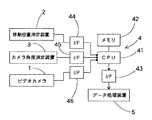
データ収集装置4は、図3に示すように、CPU41、メモリ42、インターフェース43〜46を備え、ビデオカメラ1、移動位置測定装置2、カメラ角度測定装置3、及びデータ処理装置5がインターフェース43〜46を介して接続される。このデータ収集装置4は、ビデオカメラ1が撮影する各画像フレームの作成時に同期して、つまりビデオカメラ1から入力されるタイムコード信号をトリガとして、移動位置測定装置2及びカメラ角度測定装置3から送られる測定データを取り込み、タイムコード信号と共に、緯度、経度、高度の各位置データ、ロール角、ピンチ角、方位角の各カメラ角データをデータ処理装置5に出力する。データ収集装置4からデータ処理装置5への伝送路には、例えばRS232Cが使用され、タイムコード信号と共に、各位置データ、各カメラ角データがシリアルデータとして伝送される。
【0025】
データ処理装置5は、例えばパーソナルコンピュータから構成され、ビデオカメラ1が撮影を行なう間、オンライン処理で、データ収集装置4から送られたタイムコード信号、緯度、経度、高度の各位置データ、ロール角、ピンチ角、方位角の各カメラ角データを、RS232Cポートを通して取り込み、一時メモリにそれを記憶する。その後、オフラインで、記憶した緯度データ、経度データ、高度データを読み出し、データの補正・補間を行なう。
【0026】
データの補間は、ビデオカメラが撮影した画像の各フレーム毎のタイミングで実施する。GPSを用いた移動位置測定装置2は、通常、毎秒1個乃至数個の位置データを出力し、撮影画像の各フレームの発生タイミング(1/30秒)ではデータの更新がない場合が多い。
【0027】
このため、自動車を連続移動させてカメラ撮影を行なう場合、連続して移動するカメラの位置の変化に応じて、緯度データ、経度データ、高度データが変化するように、移動位置測定装置2からの緯度、経度、高度の各位置データを、撮影画像の各フレームの発生タイミング(1/30秒)毎に線形補間或は非線形補間を用いて滑らかに補間する。また、その緯度、経度、高度の各位置データがその前後のデータと比べ大きく相違する場合、そのデータは使用せず、前後のデータに基づき、位置データを修正する。
【0028】
次に、上記構成のビデオカメラ位置角度測定装置の動作を、送電線鉄塔の景観シュミレーションのための景観撮影を例にとって説明する。図1に示す全ての装置、つまりビデオカメラ1、移動位置測定装置2、データ収集装置4、データ処理装置5は、図1のように配線・接続され、自動車内に搭載される。ビデオカメラ1は、カメラ角度測定装置3と共に自動車内の前方を向けて水平に固定され、カメラ角度測定装置3のロール角検出用のX軸(図2)を自動車の前方(直進前進方向)合わる。
【0029】
送電線鉄塔を建設する予定地の景観画像をビデオカメラにより撮影するために、予定地付近を通る道路に自動車を移動し、撮影場所の手前に自動車を止め、装置をリセットする。ジャイロを用いたカメラ角度測定装置3は、相対移動角度のみを測定しカメラの向き(方位)を検出できないため、予めスタート時のカメラの向き(絶対方位)を測定し、データ処理装置5に入力する。ビデオカメラ1つまり自動車を所定の方位(例えば真北など)に向け、そこから移動・撮影をスタートするようにしてもよい。
【0030】
全ての装置に電源投入後、自動車が完全に停止した状態で、カメラ角度測定装置3の初期化を行なう。すなわち、各ジャイロ31、32、33の出力値を収束させ、ロール角、ピッチ角、方位角の各原点を初期化し、次に、自動車のエンジンを始動した状態で、各ジャイロの出力値を測定し、その値をオフセット値として初期設定する(図4のステップ100)。
【0031】
次に、データ収集装置4及びデータ処理装置5が、移動位置測定装置2からの位置データを取り込むと共に、カメラ角度測定装置3からの角度データを取り込んで、カメラの位置と角度の計測を開始する(ステップ110)。続いて、ビデオカメラ1による撮影を開始し(ステップ120)、自動車を道路に沿って移動させながら、予定地付近の風景を撮影する。
【0032】
ビデオカメラ1は、撮影を開始すると、撮影した画像の各フレーム毎(例えば1/30秒毎)にタイムコード信号を出力し、データ収集装置4はこのタイムコード信号を同期信号(トリガ信号)として入力し、移動位置測定装置2及びカメラ角度測定装置3から送られるこの時点の測定データを取り込む(ステップ130〜140)。そして、データ収集装置4は、タイムコード信号と共に、緯度、経度、高度の各位置データ、ロール角、ピンチ角、方位角の各カメラ角データを、所定のフォーマット化されたシリアルデータとして、データ処理装置5に出力する(ステップ150)。
【0033】
データ処理装置5は、ビデオカメラ1が撮影を行なう間、オンライン処理で、データ収集装置4から送られたタイムコード信号、緯度、経度、高度の各位置データ、及びロール角、ピンチ角、方位角の各カメラ角データを取り込み、一時メモリにそれらを順に記憶していく。
【0034】
このようなデータ収集装置4とデータ処理装置5の動作により、自動車が低速で走行しながらビデオカメラ1により周囲の風景が撮影される間、撮影した画像の各フレーム毎(例えば1/30秒毎)に、撮影の視点となるビデオカメラ1の緯度、経度、高度の各位置データ、及び撮影の視線方向となるカメラのロール角、ピンチ角、方位角の各データがデータ処理装置5に蓄積される。
【0035】
そして、撮影を終了した後、データ処理装置5を使用して、カメラの位置のデータを補間・補正処理する。このデータの補間・補正は、GPSを用いた移動位置測定装置2が、通常、毎秒1個乃至数個の位置データを出力し、撮影画像の各フレームの発生タイミング(1/30秒)ではデータの更新がないために実施し、連続して移動するカメラの位置の変化に応じて、その位置(緯度、経度、高度)が連続して変化するように、収集した緯度、経度、高度の各位置データを、撮影画像の各フレームの発生タイミング(1/30秒)毎に、線形補間或は非線形補間を用いて滑らかに補間する。また、その緯度、経度、高度の各位置データがその前後のデータと比べ大きく相違する場合、そのデータは使用せず、前後のデータに基づき、位置データを修正する。
【0036】
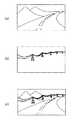
このようにして撮影されたビデオカメラ1の例えば図5aのような画像の画像データは、各フレーム毎に、そのカメラ位置データ及び角度データと共に、CG装置に入力される。そして、CG装置では、図5bのような送電線鉄塔の画像が予め作成され、この送電線鉄塔の3次元グラフィック画像と上記の撮影画像を、画像合成することにより、図5cに示すような合成ビデオ画像が作成され、景観シュミレーションのためのビデオ映像が作られる。
【0037】
画像合成は、撮影された画像データの各フレームについて、その撮影視点となる緯度、経度、高度の各位置データ、及び視線のロール角、ピンチ角、方位角の角度データをCG画像に与えた時の鉄塔の3D画像を合成するように行なわれるため、撮影した動画の風景画像上に、送電線鉄塔を正しい位置に張り付くように合成することができる。
【0038】
また、このようなフレーム毎の画像合成の作業は、各フレーム毎に視点の位置データと視線の角度データがあるため、CG装置により自動的に効率よく行なうことができ、更に、ビデオカメラ1の撮影時に収集され適正に補間・補正された各フレーム毎の位置データと角度データを使用するため、違和感のない滑らかな動画像を作ることができる。
【図面の簡単な説明】
【図1】本発明の一実施形態を示すビデオカメラ位置角度測定装置の構成図である。
【図2】カメラ角度測定装置の構成図である。
【図3】データ収集装置の構成と接続を示すブロック図である。
【図4】データ収集装置の動作を示すフローチャートである。
【図5】ビデオカメラの撮影画像(a)、CGにより作成した画像(b)、及びそれらを合成した画像(c)の説明図である。
【符号の説明】
1−ビデオカメラ
2−移動位置測定装置
3−カメラ角度測定装置
4−データ収集装置
5−データ処理装置[0001]
BACKGROUND OF THE INVENTION
The present invention relates to the position and angle of a video camera used when creating a composite video image used in a landscape simulation or the like, that is, a landscape image taken with a video camera and an image of an object created with CG (computer graphic). The present invention relates to a video camera position angle measuring apparatus for obtaining data.
[0002]
[Prior art]
Conventionally, for example, in order to see the expected completion state of a building to be constructed at the planned construction site on a simulation screen, the predicted appearance of the building is created as a three-dimensional image with CG, and a landscape image of the planned construction site is obtained by a video camera. There has been proposed an apparatus that synthesizes and displays a CG image and an image captured by a video camera (for example, JP-A-5-011727).
[0003]
[Problems to be solved by the invention]
[0004]
However, the conventional image synthesizer obtains camera direction data and position data at a speed corresponding to each frame image of a moving image when a moving image such as a landscape is shot while moving the video camera at a certain speed. There is a bug that cannot be done.
[0005]
In other words, when a video camera is mounted on, for example, an automobile and it is desired to shoot a surrounding landscape image as a moving image, the position data and direction data of the camera that change every moment during the movement are obtained for each frame image (for example, 1 An image synthesizing device obtained every 30 seconds) has not been proposed yet.
[0006]
For this reason, for example, when evaluating a landscape of a planned construction area where a structure such as a steel tower is constructed, the structure can be seen from which position by moving the area by car and photographing the surrounding scenery. There is a problem that it is impossible to create a landscape simulation image that evaluates whether the landscape changes.
[0007]
The present invention has been made in view of the above points, and measures the position and angle of a video camera that moves at the time of shooting, collects these data, and captures the shot moving image and the image of the object created by CG. It is an object of the present invention to provide a video camera position angle measuring device capable of using such data when combining.
[0008]
[Means for Solving the Problems]
In order to achieve the above object, a video camera position angle measuring device of the present invention is a video used when a moving image shot by a moving video camera and an image of an object created by CG are combined by an image combining device. In a video camera position angle measurement device for obtaining camera position and angle data,
A camera position measuring means for measuring the absolute position of the moving video camera and outputting the latitude data, longitude data, and altitude data;
Camera angle measuring means for measuring the roll angle, pitch angle and azimuth angle of the video camera during movement and outputting the roll angle data, pitch angle data and azimuth angle data;
Data collection means for collecting measurement data from the camera position measurement means and camera angle measurement means in synchronization with the creation of each image frame taken by the video camera;
While the video camera is shooting, the latitude data, the longitude data, and the altitude data output from the camera position measuring means are captured through the data collecting means, and the roll angle data and the pitch angle data are output from the camera angle measuring means. And data storage processing means for capturing and storing azimuth angle data;
Data interpolation processing means for interpolating and correcting data at a timing for each frame of an image photographed by the video camera, latitude data, longitude data, altitude data at regular intervals temporarily stored by the data storage processing means;
With
The data interpolation processing means is configured to generate each frame of the captured image at each generation timing so that the latitude data, the longitude data, and the altitude data continuously change according to a change in the position of the video camera that moves continuously. When the latitude data, longitude data and altitude data are interpolated using linear interpolation or non-linear interpolation, andthe latitude data, longitude data or altitude data are significantly different from the preceding and succeeding data, the data before and after The latitude data, longitude data, or altitude data is corrected based on the above.
[0009]
Here, as the camera position measuring means, for example, a moving position measuring device using GPS can be used. When the video camera is mounted on a vehicle and moved, the moving position measuring device is also mounted on the vehicle. As the camera angle measuring means, for example, three gyros that measure the angle of rotation about three axes can be used. Further, a processing device having a CPU as a main part can be used as the data collection means, and a general-purpose personal computer can be used as the data storage processing means and the data interpolation processing means.
[0010]
[Operation and effect of the invention]
The video camera position angle measuring device having such a configuration is mounted on a car or the like and used together with the video camera, and the camera position measuring means is used as the absolute position of the moving video camera while photographing a landscape or the like while moving. The position is measured, and the latitude data, longitude data, and altitude data are output. The camera angle measuring means measures the roll angle, pitch angle and azimuth angle of the video camera during movement, and outputs the roll angle data, pitch angle data and azimuth angle data.
[0011]
At this time, the data collection means collects measurement data from the camera position measurement means and camera angle measurement means in synchronization with the creation of each image frame taken by the video camera, and sends these data to the data storage processing means. . The data storage processing means fetches and stores these latitude data, longitude data, altitude data, roll angle data, pitch angle data, and azimuth angle data.
[0012]
Then, after storing these data, the data interpolation processing means interpolates and corrects the latitude data, longitude data, and altitude data at regular intervals at the timing of each frame of the image taken by the video camera. .
[0013]
The video camera position and angle data collected and corrected as described above are input to the CG device together with the captured image data when the captured moving image and the image of the object created by the CG are combined. And CG image viewpoint position and line-of-sight angle data are used to synthesize moving images.
[0014]
As described above, the image composition is performed by using the CG image for each frame of the captured image data, such as the latitude, longitude, altitude position data, and the gaze roll angle, pinch angle, and azimuth angle data. Therefore, the CG object image can be synthesized so as to stick to the correct position on the captured moving image.
[0015]
Also, the image synthesis work for each frame has viewpoint position data and line-of-sight angle data for each frame, so it can be automatically and efficiently performed by the CG device, and is further collected at the time of video camera shooting. Since the position data and the angle data for each frame that are appropriately interpolated and corrected are used, a smooth moving image without any sense of incongruity can be created, and it can be used effectively for landscape simulation.
[0016]
DETAILED DESCRIPTION OF THE INVENTION
Hereinafter, embodiments of the present invention will be described with reference to the drawings. FIG. 1 shows a block diagram of an apparatus according to an embodiment of the present invention. As shown in FIG. 1, this video camera position angle measuring device is mounted on a car and shoots a landscape or the like and records a moving image on a magnetic tape or the like. A moving
[0017]
Furthermore, the video camera position angle measuring device measures the roll angle, pitch angle and azimuth angle of the
[0018]
The
[0019]
Further, at the time of shooting, the
[0020]
The moving
[0021]
In order to increase the measurement accuracy of GPS, a combination with a self-contained navigation of an automobile can be employed in addition to a map matching method. In the self-contained navigation, the azimuth is measured using a geomagnetic sensor, a gyro, a wheel speed sensor that calculates the azimuth based on the rotation difference between the left and right wheels, and the positioning data by GPS is corrected. A reference station with a known precise position receives a GPS signal from a GPS satellite, calculates the error data by comparing the positioning data calculated from the GPS signal and the known position data, and broadcasts the error data. It is also possible to employ so-called DGPS, which is transmitted to an automobile on radio waves or the like, and a GPS device on the automobile corrects GPS positioning data based on the error data.
[0022]
As shown in FIG. 2, the camera
[0023]
That is, in order to measure the left and right tilt angles (roll angles) with respect to the moving direction of the
[0024]
As shown in FIG. 3, the data collection device 4 includes a
[0025]
The
[0026]
Data interpolation is performed at the timing of each frame of the image captured by the video camera. The moving
[0027]
For this reason, when the camera is photographed by continuously moving the vehicle, the moving
[0028]
Next, the operation of the video camera position angle measuring apparatus having the above-described configuration will be described by taking landscape photography for landscape simulation of a transmission line tower as an example. All the devices shown in FIG. 1, that is, the
[0029]
In order to capture a landscape image of the planned site for constructing the transmission line tower with a video camera, the vehicle is moved to a road passing through the vicinity of the planned site, the vehicle is stopped in front of the shooting site, and the device is reset. Since the camera
[0030]
After turning on all the devices, the camera
[0031]
Next, the data collection device 4 and the
[0032]
When the
[0033]
While the
[0034]
By such operations of the data collection device 4 and the
[0035]
Then, after the photographing is finished, the
[0036]
The image data of the
[0037]
In image synthesis, for each frame of the captured image data, the latitude, longitude, altitude position data as the shooting viewpoint, and angle roll angle, pinch angle, and azimuth angle data are given to the CG image. Since the 3D image of the steel tower is synthesized, it is possible to synthesize the power transmission line tower so as to stick to the correct position on the captured landscape image of the moving image.
[0038]
In addition, since the image composition work for each frame has viewpoint position data and line-of-sight angle data for each frame, it can be automatically and efficiently performed by the CG device. Since the position data and angle data for each frame collected and properly interpolated and corrected at the time of shooting are used, a smooth moving image without a sense of incongruity can be created.
[Brief description of the drawings]
FIG. 1 is a configuration diagram of a video camera position angle measuring apparatus showing an embodiment of the present invention.
FIG. 2 is a configuration diagram of a camera angle measurement apparatus.
FIG. 3 is a block diagram showing the configuration and connection of the data collection device.
FIG. 4 is a flowchart showing the operation of the data collection device.
FIG. 5 is an explanatory diagram of a captured image (a) of a video camera, an image (b) created by CG, and an image (c) obtained by combining them.
[Explanation of symbols]
1-video camera 2-moving position measuring device 3-camera angle measuring device 4-data collecting device 5-data processing device
Claims (2)
Translated fromJapanese移動するビデオカメラの絶対位置を測定し、その緯度データ、経度データ、高度データを出力するカメラ位置測定手段と、
移動時の該ビデオカメラのロール角、ピッチ角及び方位角を測定し、そのロール角データ、ピッチ角データ及び方位角データを出力するカメラ角度測定手段と、
該ビデオカメラが撮影する各画像フレームの作成時に同期して、該カメラ位置測定手段及びカメラ角度測定手段からの測定データを収集するデータ収集手段と、
該ビデオカメラが撮影を行なう間、該データ収集手段を通して該カメラ位置測定手段から出力される緯度データ、経度データ、高度データを取り込み、該カメラ角度測定手段から出力されるロール角データ、ピッチ角データ及び方位角データを取り込み記憶するデータ記憶処理手段と、
該データ記憶処理手段が一時記憶した一定時間毎の緯度データ、経度データ、高度データを、前記ビデオカメラが撮影した画像の各フレーム毎のタイミングでデータの補間及び補正を行なうデータ補間処理手段と、
を備え、
該データ補間処理手段は、連続して移動する該ビデオカメラの位置の変化に応じて、前記緯度データ、経度データ及び高度データが連続して変化するように、撮影画像の各フレームの発生タイミング毎に、線形補間または非線形補間を用いて、該緯度データ、経度データ及び高度データの補間を行い、該緯度データ、経度データまたは高度データがその前後のデータと比べ大きく相違する場合、その前後のデータに基づき、該緯度データ、経度データまたは高度データを修正することを特徴とするビデオカメラ位置角度測定装置。In a video camera position and angle measurement device for obtaining data of position and angle of a video camera used when a moving image shot by a moving video camera and an image of an object created by CG are combined by an image combining device,
A camera position measuring means for measuring the absolute position of the moving video camera and outputting the latitude data, longitude data, and altitude data;
Camera angle measuring means for measuring the roll angle, pitch angle and azimuth angle of the video camera during movement and outputting the roll angle data, pitch angle data and azimuth angle data;
Data collection means for collecting measurement data from the camera position measurement means and camera angle measurement means in synchronization with the creation of each image frame taken by the video camera;
While the video camera is shooting, the latitude data, the longitude data, and the altitude data output from the camera position measuring means are captured through the data collecting means, and the roll angle data and the pitch angle data are output from the camera angle measuring means. And data storage processing means for capturing and storing azimuth angle data;
Data interpolation processing means for interpolating and correcting data at a timing for each frame of an image photographed by the video camera, latitude data, longitude data, altitude data at regular intervals temporarily stored by the data storage processing means;
With
The data interpolation processing means is configured to generate each frame of the captured image at each generation timing so that the latitude data, the longitude data, and the altitude data continuously change according to a change in the position of the video camera that moves continuously. When the latitude data, longitude data and altitude data are interpolated using linear interpolation or non-linear interpolation, andthe latitude data, longitude data or altitude data are significantly different from the preceding and succeeding data, the data before and after A video camera position angle measuring devicewhich corrects the latitude data, longitude data or altitude data based on
Priority Applications (1)
| Application Number | Priority Date | Filing Date | Title |
|---|---|---|---|
| JP07886098AJP3796704B2 (en) | 1998-03-26 | 1998-03-26 | Video camera position angle measuring device |
Applications Claiming Priority (1)
| Application Number | Priority Date | Filing Date | Title |
|---|---|---|---|
| JP07886098AJP3796704B2 (en) | 1998-03-26 | 1998-03-26 | Video camera position angle measuring device |
Publications (2)
| Publication Number | Publication Date |
|---|---|
| JPH11271060A JPH11271060A (en) | 1999-10-05 |
| JP3796704B2true JP3796704B2 (en) | 2006-07-12 |
Family
ID=13673591
Family Applications (1)
| Application Number | Title | Priority Date | Filing Date |
|---|---|---|---|
| JP07886098AExpired - Fee RelatedJP3796704B2 (en) | 1998-03-26 | 1998-03-26 | Video camera position angle measuring device |
Country Status (1)
| Country | Link |
|---|---|
| JP (1) | JP3796704B2 (en) |
Families Citing this family (6)
| Publication number | Priority date | Publication date | Assignee | Title |
|---|---|---|---|---|
| US20120281102A1 (en)* | 2010-02-01 | 2012-11-08 | Nec Corporation | Portable terminal, activity history depiction method, and activity history depiction system |
| JP2014175701A (en)* | 2013-03-06 | 2014-09-22 | Nippon Hoso Kyokai <Nhk> | Imaging apparatus, imaging method, editing apparatus, and editing method |
| JP2015015775A (en)* | 2014-10-22 | 2015-01-22 | レノボ・イノベーションズ・リミテッド(香港) | Geographical feature display system, mobile terminal, geographical feature display method, and program |
| US10682911B2 (en)* | 2016-02-18 | 2020-06-16 | Sony Corporation | Active window for vehicle infomatics and virtual reality |
| JP7102173B2 (en)* | 2018-03-09 | 2022-07-19 | キヤノン株式会社 | Information processing equipment, information processing methods, and programs |
| JP2023062983A (en)* | 2021-10-22 | 2023-05-09 | 中部電力株式会社 | Virtual tower display system |
- 1998
- 1998-03-26JPJP07886098Apatent/JP3796704B2/ennot_activeExpired - Fee Related
Also Published As
| Publication number | Publication date |
|---|---|
| JPH11271060A (en) | 1999-10-05 |
Similar Documents
| Publication | Publication Date | Title |
|---|---|---|
| JP4560128B1 (en) | Map image integrated database generation system and map image integrated database generation program | |
| CN110675450B (en) | Method and system for generating orthoimage in real time based on SLAM technology | |
| KR101223242B1 (en) | Apparatus for drawing digital map | |
| CN1788188B (en) | Captured image display method and captured image display device | |
| JP4010753B2 (en) | Shape measuring system, imaging device, shape measuring method, and recording medium | |
| JP4469471B2 (en) | Wide viewing angle multidirectional image acquisition device for moving body and wide viewing angle multidirectional image acquisition system for moving body | |
| JP3725982B2 (en) | Position acquisition device | |
| JP5738657B2 (en) | Imaging device | |
| KR101308744B1 (en) | System for drawing digital map | |
| JPH08159762A (en) | Method and apparatus for extracting three-dimensional data and stereo image forming apparatus | |
| JP2010014443A (en) | Position measurement method, position measurement device, and program | |
| US20110249095A1 (en) | Image composition apparatus and method thereof | |
| US20030218675A1 (en) | Video picture processing method | |
| JP2019039851A (en) | Photogrammetry system and photogrammetry method | |
| JP3796704B2 (en) | Video camera position angle measuring device | |
| KR20030056284A (en) | Method and system for extraction a road institution body information using a vehicles | |
| KR101296601B1 (en) | The camera control system and method for producing the panorama of map information | |
| JP2019110434A (en) | Image processing apparatus, image processing system, and program | |
| JP6412400B2 (en) | Image composition apparatus and image composition program | |
| JPH099197A (en) | Continuous stereo image data recorder | |
| CN114586335A (en) | Image processing apparatus, image processing method, program, and recording medium | |
| JP4409116B2 (en) | Video / position information recording device | |
| JPH0737065A (en) | Method and device for preparing development picture | |
| JP2020167499A (en) | Photographing support device | |
| JP2003296329A (en) | Information providing apparatus, information providing method, and information processing program |
Legal Events
| Date | Code | Title | Description |
|---|---|---|---|
| A621 | Written request for application examination | Free format text:JAPANESE INTERMEDIATE CODE: A621 Effective date:20040419 | |
| A977 | Report on retrieval | Free format text:JAPANESE INTERMEDIATE CODE: A971007 Effective date:20050714 | |
| A131 | Notification of reasons for refusal | Free format text:JAPANESE INTERMEDIATE CODE: A131 Effective date:20050726 | |
| A521 | Request for written amendment filed | Free format text:JAPANESE INTERMEDIATE CODE: A523 Effective date:20050916 | |
| A131 | Notification of reasons for refusal | Free format text:JAPANESE INTERMEDIATE CODE: A131 Effective date:20051018 | |
| A521 | Request for written amendment filed | Free format text:JAPANESE INTERMEDIATE CODE: A523 Effective date:20051213 | |
| TRDD | Decision of grant or rejection written | ||
| A01 | Written decision to grant a patent or to grant a registration (utility model) | Free format text:JAPANESE INTERMEDIATE CODE: A01 Effective date:20060307 | |
| A61 | First payment of annual fees (during grant procedure) | Free format text:JAPANESE INTERMEDIATE CODE: A61 Effective date:20060406 | |
| R150 | Certificate of patent or registration of utility model | Free format text:JAPANESE INTERMEDIATE CODE: R150 | |
| FPAY | Renewal fee payment (event date is renewal date of database) | Free format text:PAYMENT UNTIL: 20130428 Year of fee payment:7 | |
| LAPS | Cancellation because of no payment of annual fees |