JP3796253B2 - Liquid crystal display - Google Patents
Liquid crystal displayDownload PDFInfo
- Publication number
- JP3796253B2 JP3796253B2JP2004192577AJP2004192577AJP3796253B2JP 3796253 B2JP3796253 B2JP 3796253B2JP 2004192577 AJP2004192577 AJP 2004192577AJP 2004192577 AJP2004192577 AJP 2004192577AJP 3796253 B2JP3796253 B2JP 3796253B2
- Authority
- JP
- Japan
- Prior art keywords
- liquid crystal
- image data
- crystal display
- input image
- display device
- Prior art date
- Legal status (The legal status is an assumption and is not a legal conclusion. Google has not performed a legal analysis and makes no representation as to the accuracy of the status listed.)
- Expired - Fee Related
Links
Images


Landscapes
- Liquid Crystal Display Device Control (AREA)
- Transforming Electric Information Into Light Information (AREA)
- Control Of Indicators Other Than Cathode Ray Tubes (AREA)
- Liquid Crystal (AREA)
Description
Translated fromJapanese本発明は、液晶表示パネルを用いて画像を表示する液晶表示装置に関し、特に液晶表示パネルの応答速度を向上させることができる加速駆動に関するものである。The present inventionrelates to a liquid crystal displaydevice that displays an image by using aliquid crystal display panel, and more particularly relatesto an acceleration drivemovement can improve the response speed of the liquid crystal display panel.
昨今の画像表示装置は、PC用TV用ともにブラウン管(CRT)にとってかわり、液晶表示装置(LCD)が広く使用されるようになってきている。LCDは二つの基板の間に注入されている異方性誘電率を有する液晶層に電界を印加し、この電界の強さを調節して基板を透過する光の量を調節することによって所望の画像信号を得る表示装置である。 Recent image display devices have been replaced by cathode ray tubes (CRT) for both PC TVs, and liquid crystal display devices (LCD) have been widely used. The LCD applies an electric field to a liquid crystal layer having an anisotropic dielectric constant injected between two substrates, and adjusts the amount of light transmitted through the substrate by adjusting the strength of the electric field. A display device that obtains an image signal.
現在、LCDの性能を出来る限りブラウン管に近づけようと様々な研究が行われているが、液晶の応答速度の改善もその一つである。液晶の応答速度を速める方法としては、液晶材の最適化や液晶セルの厚み(セルギャップ)を小さくするなど様々な試みがなされているが、他方、液晶自体の性能によらず、その駆動方法を工夫することで応答速度を速めようとする研究が行われている。 At present, various studies are being made to bring the performance of the LCD as close as possible to the cathode ray tube. Improvement of the response speed of the liquid crystal is one of them. Various attempts have been made to increase the response speed of the liquid crystal, such as optimizing the liquid crystal material and reducing the thickness of the liquid crystal cell (cell gap). On the other hand, the driving method is independent of the performance of the liquid crystal itself. Research is being conducted to improve the response speed by devising.
このような液晶の応答速度の問題を改善するために、1垂直期間前の入力画像信号と現垂直期間の入力画像信号の組み合わせに応じて、予め決められた現垂直期間の入力画像信号に対する階調電圧より高い(オーバーシュートされた)駆動電圧或いはより低い(アンダーシュートされた)駆動電圧を液晶表示パネルに供給する液晶駆動方法が知られている。以下、本願明細書においては、この駆動方式を加速駆動と定義する。 In order to improve such a response speed problem of the liquid crystal, the level of the input image signal in the current vertical period determined in advance according to the combination of the input image signal in the previous vertical period and the input image signal in the current vertical period. There is known a liquid crystal driving method for supplying a liquid crystal display panel with a driving voltage higher (overshooted) or lower (undershooted) than a regulated voltage. Hereinafter, in the present specification, this driving method is defined as acceleration driving.
例えば特開平4−365094号公報には、表示用デジタル画像データを1フレーム分記憶する画像メモリと、上記デジタル画像データと上記画像メモリから1フレーム遅れて読出される画像データの2入力に対応する画像データを格納したテーブルを記憶したROMとを備え、画像データが変化した場合にはその変化の方向と度合いに応じて予め格納してある最適な画像データを読出して液晶パネルを駆動することにより、その光透過率の立上りあるいは立下がりを必要充分な範囲で急峻とさせて、液晶の応答速度を向上させるものが提案されている。 For example, Japanese Patent Laid-Open No. 4-365094 corresponds to two inputs of an image memory for storing display digital image data for one frame, and the digital image data and image data read from the image memory with a delay of one frame. A ROM storing a table storing image data, and when the image data changes, the optimum image data stored in advance is read according to the direction and degree of the change, and the liquid crystal panel is driven. In order to improve the response speed of the liquid crystal, the rise or fall of the light transmittance is made steep within a necessary and sufficient range.
ここで、ROMに格納されるテーブルは、例えば表示信号レベル数すなわち表示データ数が8ビットの256階調である場合、256の全ての階調に対する書込階調データを持っていても良いし、例えば図11に示すように、32階調毎の9つの代表階調についての強調変換パラメータ(実測値)のみを記憶しておき、その他の書込階調データについては、上記強調変換パラメータから線形補完等の演算で求めるようにしても良い。 Here, for example, when the number of display signal levels, that is, the number of display data is 8 bits of 256 gradations, the table stored in the ROM may have write gradation data for all 256 gradations. For example, as shown in FIG. 11, only the enhancement conversion parameters (actually measured values) for nine representative gradations for every 32 gradations are stored, and the other writing gradation data is obtained from the above enhancement conversion parameters. You may make it obtain | require by calculation, such as a linear complement.
一般的に液晶表示パネルにおいては、ある中間調から別の中間調に変更させる時間は長く、中間調を1フィールド(約16.6m秒)内に表示することができず、残像が発生するだけでなく、中間調を正しく表示することができないという課題があったが、上述の加速駆動を用いることにより、液晶表示パネルの光学応答特性を補償して、目標の中間調を短時間で表示することが可能となる。
しかしながら、上述した従来の液晶表示装置においては、1フレーム(フィールド)前に対して現フレーム(フィールド)の入力画像データが最上位データまたは最下位データ付近に遷移した場合、加速駆動が適切に動作しないため、液晶表示パネルの光学応答特性を補償することができず、残像や尾引きの発生を招来するという問題があった。 However, in the above-described conventional liquid crystal display device, when the input image data of the current frame (field) transitions to the uppermost data or the vicinity of the lowermost data with respect to one frame (field) before, the acceleration drive operates appropriately. Therefore, the optical response characteristics of the liquid crystal display panel cannot be compensated, and there is a problem that afterimages and tailing occur.
例えば、表示信号レベル数すなわち表示データ数が8ビットの256階調である場合、最大階調である255以上の階調データや最小階調である0以下の階調データを液晶表示パネルに書き込むことはできず、最大階調データまたは最小階調データ付近に階調遷移した場合、液晶の応答速度を改善することができない。 For example, when the number of display signal levels, that is, the number of display data is 256 bits of 8 bits, the gradation data of 255 or more which is the maximum gradation or the gradation data of 0 or less which is the minimum gradation is written to the liquid crystal display panel. However, the response speed of the liquid crystal cannot be improved when the gradation transitions near the maximum gradation data or the minimum gradation data.
すなわち、1フィールド前の入力画像データが128階調で、現フィールドの入力画像データが255階調である場合、図12に示すように、出力表示階調は1フィールド内に目標到達階調である255階調に到達していない(すなわち、1フィールド内に液晶が応答していない)が、加速駆動を行っても255階調以上にデータ強調することができないため、液晶表示パネルの光学応答特性を補償することができない。 That is, when the input image data of the previous field is 128 gradations and the input image data of the current field is 255 gradations, as shown in FIG. 12, the output display gradation is the target achievement gradation within one field. Although some 255 gradations have not been reached (that is, the liquid crystal has not responded within one field), the data response cannot be enhanced to 255 gradations or more even if acceleration driving is performed, so the optical response of the liquid crystal display panel The characteristic cannot be compensated.
従って、従来の液晶表示装置の場合、中間調に遷移する入力画像データに対しては、加速駆動によるデータ強調を行うことで、液晶表示パネルの光学応答特性を補償して、残像や尾引きの発生を抑制することが可能であるが、低階調または高階調付近に遷移する入力画像データについては、加速駆動によるデータ強調を行うことができず、残像や尾引きが発生して、表示画像の画質を向上させることができないという問題があった。 Therefore, in the case of a conventional liquid crystal display device, the input image data transitioning to a halftone is compensated for the optical response characteristics of the liquid crystal display panel by performing data enhancement by acceleration driving, and thus the afterimage and tailing are corrected. Although it is possible to suppress the occurrence, for input image data that transitions to low gradation or near high gradation, data enhancement by acceleration drive cannot be performed, and afterimages and tailing occur, resulting in a display image There was a problem that the image quality of the camera could not be improved.
本発明は、上記課題に鑑みてなされたものであり、低階調または高階調付近に遷移する入力画像データに対しても、加速駆動によるデータ強調を可能とし、液晶表示パネルの光学応答特性を補償して、残像や尾引きの発生を抑制することができる液晶表示装置を提供するものである。The present invention has been made in view of the above problems, and enables data enhancement by acceleration driving even for input image data transitioning to a low gradation or a high gradation, and the optical response characteristics of a liquid crystal display panel are improved. It is an object of the presentinvention to provide a liquid crystal displaydevice that can compensate for the occurrence of afterimages and tailing.
本願の第1の発明は、少なくとも1垂直期間前の入力画像データと現垂直期間の入力画像データとの比較を行い、該比較結果から得られる強調変換パラメータに基づいて、入力画像データを強調データに変換した上で液晶表示パネルへ出力することにより、前記液晶表示パネルを加速駆動する液晶表示装置であって、前記入力画像データに対して、ダイナミックレンジを小さくする階調変換を行う手段と、前記液晶パネルの温度に基づいて、前記ダイナミックレンジの変換特性を可変制御する手段とを備えたことを特徴とする。Thefirst invention of the present applicationcompares at least one input image data before the vertical period with the input image data of the current vertical period, and converts the input image data into the enhancement data based on the enhancement conversion parameter obtained from the comparison result. A liquid crystal display device for accelerating and driving the liquid crystal display panel by outputting to the liquid crystal display panel and converting the input image data to gradation conversion for reducing a dynamic range; Andmeans for variably controlling the conversion characteristics of the dynamic range based on the temperature of the liquid crystal panel.
本願の第2の発明は、少なくとも1垂直期間前の入力画像データと現垂直期間の入力画像データとの比較を行い、該比較結果から得られる強調変換パラメータに基づいて、入力画像データを強調データに変換した上で液晶表示パネルへ出力することにより、前記液晶表示パネルを加速駆動する液晶表示装置であって、前記入力画像データに対して、ダイナミックレンジを小さくする階調変換を行う手段と、前記入力画像データの特徴に基づいて、前記ダイナミックレンジの変換特性を可変制御する手段とを備えたことを特徴とする。Thesecond invention of the present applicationcompares the input image data of at least one vertical period before the input image data of the current vertical period, and converts the input image data into the emphasis data based on the emphasis conversion parameter obtained from the comparison result. A liquid crystal display device for accelerating and driving the liquid crystal display panel by outputting to the liquid crystal display panel and converting the input image data to gradation conversion for reducing a dynamic range; Andmeans for variably controlling the conversion characteristics of the dynamic range based on the characteristics of the input image data.
本願の第3の発明は、前記入力画像データの特徴が、前記入力画像データの動き量であることを特徴とする。Athird invention of the present application is characterized in that the feature of the input image data is a motion amount of the input image data.
本願の第4の発明は、前記入力画像データの特徴が、前記入力画像データのフレームレートであることを特徴とする。Afourth invention of the present application is characterized in that the feature of the input image data is a frame rate of the input image data.
本願の第5の発明は、前記入力画像データの特徴が、前記入力画像データの発生源であることを特徴とする液晶表示装置。According to afifth aspect of the present invention, in the liquid crystal display device, the feature of the input image data is a source of the input image data.
本願の第6の発明は、前記ダイナミックレンジの変換特性を1画面単位で可変制御することを特徴とする。Asixth invention of the present application is characterized in that the dynamic range conversion characteristics are variably controlled in units of one screen.
本願の第7の発明は、前記ダイナミックレンジの変換特性を画面内の所定領域単位で可変制御することを特徴とする。Theseventh invention of the present application is characterized in that the conversion characteristic of the dynamic range is variably controlled in units of a predetermined area in the screen.
本願の第8の発明は、少なくとも1垂直期間前の入力画像データと現垂直期間の入力画像データとの比較を行い、該比較結果から得られる強調変換パラメータに基づいて、入力画像データを強調データに変換した上で液晶表示パネルへ出力することにより、前記液晶表示パネルを加速駆動する液晶表示装置であって、前記入力画像データに対して、ダイナミックレンジを小さくする階調変換を行う手段と、ユーザによる指示入力に基づいて、前記ダイナミックレンジの変換特性を可変制御する手段とを備えたことを特徴とする。Theeighth invention of the present applicationcompares the input image data of at least one vertical period before the input image data of the current vertical period, and converts the input image data into the emphasis data based on the emphasis conversion parameter obtained from the comparison result. A liquid crystal display device for accelerating and driving the liquid crystal display panel by outputting to the liquid crystal display panel and converting the input image data to gradation conversion for reducing a dynamic range; based on an instruction input by a user,characterized in that the conversion characteristic of the dynamic range and means for variably controlling.
本願発明の液晶表示装置によれば、入力画像データに対して、ダイナミックレンジを小さくする階調変換を行っているので、入力画像データが如何なる階調に遷移した場合であっても適切なデータ強調を行うことが可能であり、残像や尾引きの発生を抑制して、高品質な画像表示を実現することができる。According to the liquid crystal displaydevice of the present invention, gradation conversion that reduces the dynamic range is performed on the input image data, so that appropriate data emphasis can be achieved regardless of the gradation of the input image data. It is possible to perform high-quality image display by suppressing the occurrence of afterimages and tailing.
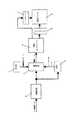
以下、本発明の第1実施形態を、図1乃至図5とともに詳細に説明する。ここで、図1は本実施形態の液晶表示装置における要部概略構成を示すブロック図、図2は本実施形態の液晶表示装置におけるROMのテーブル内容を示す概略説明図、図3は本実施形態の液晶表示装置における階調変換部の変換特性(入出力特性)の一例を示す説明図、図4は本実施形態の液晶表示装置における液晶の応答動作を示す説明図、図5は本実施形態の液晶表示装置における階調変換部の変換特性(入出力特性)他の例を示す説明図である。 Hereinafter, a first embodiment of the present invention will be described in detail with reference to FIGS. Here, FIG. 1 is a block diagram showing a schematic configuration of a main part of the liquid crystal display device of the present embodiment, FIG. 2 is a schematic explanatory diagram showing contents of a ROM table in the liquid crystal display device of the present embodiment, and FIG. FIG. 4 is an explanatory diagram illustrating an example of conversion characteristics (input / output characteristics) of a gradation conversion unit in the liquid crystal display device, FIG. 4 is an explanatory diagram illustrating a liquid crystal response operation in the liquid crystal display device of the present embodiment, and FIG. It is explanatory drawing which shows the other example of the conversion characteristic (input / output characteristic) of the gradation conversion part in the liquid crystal display device.
図1において、1は入力画像データの階調変化に応じた強調変換パラメータを格納しているROM、2はフレームメモリ(FM)、3は現フィールドの画像データとFM2から読出された前フィールドの画像データとを比較し、該比較結果(階調遷移)に対応する強調変換パラメータをROM1から読出して、強調データ(補正画像データ)を決定/出力する演算器、4は演算器3からの強調データに基づいて、液晶パネル5のゲートドライバ6及びソースドライバ7に液晶駆動信号を出力する液晶コントローラである。 In FIG. 1, 1 is a ROM that stores emphasis conversion parameters corresponding to gradation changes of input image data, 2 is a frame memory (FM), 3 is image data of the current field and the previous field read from FM2. An arithmetic unit that compares the image data with each other, reads an emphasis conversion parameter corresponding to the comparison result (gradation transition) from the
また、8は入力画像データの階調数(表示信号レベル数)を、液晶パネル5の表示階調数(表示データ数)より小さくするように変換した上で、フレームメモリ2及び演算器3に出力する階調変換部であり、液晶パネル5の表示データ数が8ビットの256階調である場合、表示信号レベル数を255階調より少ない階調数に変換するものである。
階調変換部8は、例えば図2に示すような入出力特性(階調変換特性)を持つ演算器、LUTテーブルなどによって構成することができる。ここでは、表示信号レベル数が256階調(0〜255)である入力画像データを、液晶表示パネル6の表示データ数(=256階調)より小さな224階調(16〜239)に変換しており、すなわち、入力画像データのダイナミックレンジを狭くする処理を行っている。 The
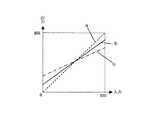
また、ROM1は、1フィールド前後の入力画像データの階調遷移に対応した強調変換パラメータを格納したテーブルが記憶されており、階調変換後の表示信号レベル数がN階調である場合、N×Nの全ての階調遷移パターンに対する強調変換パラメータを持っていても良いが、ここではROM1のメモリ容量を低減するために、例えば図3に示すような、M(<N)階調毎の9つの代表階調についての9×9の強調変換パラメータ(実測値)のみを記憶したテーブルを用いて構成している。 The
尚、ROM1の変換テーブルは、図2に示した階調変換部8の入出力特性に合わせるため、1フィールド前後の16、44、72、100、128、156、184、212、239階調に対する強調変換パラメータを格納している。この強調変換パラメータは、図9に示した従来の変換テーブルにおける0、32、64、96、128、160、192、224、255階調に対するものと同じであり、ROM1の内容は実質変更されていない。 Note that the conversion table of the
演算器3は、1フィールド前後の入力データの階調遷移に応じて、ROM1を参照することにより、対応する強調変換パラメータを読出し、この強調変換パラメータに線形補完等の演算を施すことで、すべての階調遷移に対して液晶コントローラ4に出力する強調データ(補正画像データ)を決定することができる。 The computing unit 3 reads out the corresponding enhancement conversion parameter by referring to the
例えば、1フィールド前の入力画像データが128階調で、現フィールドの入力画像データが255階調である場合、本実施形態においては、現フィールドデータを239階調に変換した上で加速駆動を行って、255階調の強調データ(補正階調データ)を液晶コントローラ4へ出力している。従って、図4に示すように、出力データ(書込階調データ)は図10に示した従来例と同じであるが、目標到達階調が239階調に下がるため、1フィールド内の液晶応答が可能となり、残像や尾引きが発生しない高品位の画像表示を実現することができる。 For example, when the input image data of the previous field has 128 gradations and the input image data of the current field has 255 gradations, in this embodiment, the current field data is converted to 239 gradations and then accelerated driving is performed. As a result, 255 gradation enhancement data (corrected gradation data) is output to the
ここで、上述のように、階調(ダイナミックレンジ)変換処理を行うことによって、階調表現数は減少することになり、表示画像のコントラストが低下することとなるが、その分残像や尾引きの発生を抑制することが可能になるため、総合的な画質は向上する。 Here, as described above, the gradation (dynamic range) conversion processing reduces the number of gradation representations and decreases the contrast of the display image. Therefore, the overall image quality is improved.
また、液晶パネル5の光学応答特性(速度)は、液晶の配向モードや液晶材料に電界を印加するための電極構造などによって変化するので、この液晶パネル5の光学応答特性に応じて、上記階調変換部8の変換特性を設定することで、より有効な画質改善が可能となる。 Further, the optical response characteristic (speed) of the
例えば、ノーマリーブラックモードの液晶パネルであって、低階調(0階調)付近へ遷移する場合の応答速度は速いが、高階調(255階調)付近へ遷移する場合の応答速度が遅い液晶パネルを用いる場合は、階調変換部8の変換特性(入出力特性)を、図5に示すような特性とすることによって、低階調(黒)側のコントラストを維持しつつ、高階調(白)側で発生する残像や尾引きを抑制することが可能となる。 For example, in a normally black mode liquid crystal panel, the response speed is fast when transitioning to a low gradation (0 gradation), but the response speed is slow when transitioning to a high gradation (255 gradation). In the case of using a liquid crystal panel, the conversion characteristics (input / output characteristics) of the
以上のように、本実施形態によれば、入力画像データの階調数を、液晶パネル5の表示階調数より小さくするように変換した上で、加速駆動を行っているため、入力画像データが如何なる階調に遷移した場合であっても、これにデータ強調を施すことが可能となり、残像や尾引きの発生を抑制して、高品質な画像表示を実現することができる。 As described above, according to the present embodiment, since the number of gradations of the input image data is converted to be smaller than the number of display gradations of the
尚、上記実施形態においては、ROM1、演算器3により強調変換処理を行っているが、ROM1を設ける代わりに、例えば遷移前の階調と遷移後の階調とを変数とする2次元関数f(pre,cur)により、液晶パネル5の光学応答特性を補償する強調データを求める構成としても良い。 In the above embodiment, the emphasis conversion process is performed by the
また、上記実施形態では、1フィールド前の画像データと現フィールドの画像データとを比較し、該比較結果から得られる強調変換パラメータを用いて、液晶パネル5の応答速度を改善しているが、例えば2フィールド前、3フィールド前の画像データをも用いて、強調変換パラメータを求めるような構成としても良いことは言うまでもない。 In the above embodiment, the image data of the previous field is compared with the image data of the current field, and the response speed of the
次に、本発明の第2実施形態について、図6乃至図8とともに詳細に説明するが、上述した第1実施形態と同一部分には同一符号を付し、その説明は省略する。ここで、図6は本実施形態の液晶表示装置における要部概略構成の一例を示すブロック図、図7は本実施形態の液晶表示装置における階調変換部の変換特性(入出力特性)を示す説明図、図8は本実施形態の液晶表示装置における要部概略構成の他の例を示すブロック図である。 Next, a second embodiment of the present invention will be described in detail with reference to FIGS. 6 to 8, but the same parts as those in the first embodiment described above are denoted by the same reference numerals, and the description thereof is omitted. Here, FIG. 6 is a block diagram showing an example of a schematic configuration of the main part of the liquid crystal display device of the present embodiment, and FIG. 7 shows the conversion characteristics (input / output characteristics) of the gradation conversion unit in the liquid crystal display device of the present embodiment. FIG. 8 is an explanatory diagram and FIG. 8 is a block diagram showing another example of the schematic configuration of the main part of the liquid crystal display device of the present embodiment.
本実施形態の液晶表示装置は、図6に示すように、入力画像データに対して所定の階調変換処理を施す階調変換部18と、装置内温度を検出するためのサーミスタ9と、サーミスタ9からの電圧値(検出温度)に対してヒステリシス処理を施し、階調変換部18の変換特性(入出力特性)を切替制御するための制御信号を出力するマイコン10とを備えている。尚、サーミスタ9は、できるだけ液晶パネル5の温度を正確に検出することが可能な位置に設けられるのが望ましい。 As shown in FIG. 6, the liquid crystal display device according to the present embodiment includes a
ここで、階調変換部18は、例えば図7に示すように、3つの階調変換特性(入出力特性)a〜cを有する演算器、LUTテーブルなどによって構成されており、この入出力特性a〜cがマイコン10から供給される制御信号に応じて切換えられる。ここで、図7中の破線で示す入出力特性aは、入力データ階調をそのまま無変換で出力する特性であることを示している。 Here, for example, as shown in FIG. 7, the
すなわち、液晶の応答速度は温度依存性が非常に大きく、特に液晶パネル5の温度が低下した状態においては、液晶の応答速度が遅くなるため、残像や尾引きが発生して、表示品位を著しく損なう。そこで、本実施形態においては、環境温度に応じて入力画像データのダイナミックレンジを可変制御することにより、常に良好な画像表示を実現可能としている。 That is, the response speed of the liquid crystal is very temperature-dependent, and particularly when the temperature of the
例えば、通常温度時においては、入出力特性bを選択して、コントラストの低下を最小限に抑えつつ、残像や尾引きの発生を防止する。また、高温使用時においては、液晶の応答速度は早く、残像や尾引きが発生する可能性が低くなるため、入出力特性a(無変換特性)を選択して、コントラストの維持を優先する。一方、低温使用時においては、液晶の応答速度は遅く、残像や尾引きが発生する可能性が高いため、入出力特性cを選択して、コントラストを多少犠牲にしても、残像や尾引きの発生が抑制されるように制御する。 For example, at the normal temperature, the input / output characteristic b is selected to prevent afterimages and tailing while minimizing contrast degradation. In addition, when using at a high temperature, the response speed of the liquid crystal is fast, and the possibility of occurrence of afterimages and tailing is reduced. Therefore, the input / output characteristic a (non-conversion characteristic) is selected and priority is given to maintaining the contrast. On the other hand, when using at low temperatures, the response speed of the liquid crystal is slow, and there is a high possibility that afterimages and tailing will occur. Control so that generation is suppressed.
以上のように、本実施形態によれば、環境温度に応じて、コントラストの維持とトレードオフの関係にある残像や尾引きの抑制処理を適切に制御することができるので、どのような環境下であっても総合的な画質を向上させることが可能である。ここで、上記階調変換特性の切換制御が画面(フレーム)単位で行なわれることは言うまでもない。 As described above, according to the present embodiment, it is possible to appropriately control the afterimage and tailing suppression processing that is in a trade-off relationship with the maintenance of contrast according to the environmental temperature. Even so, it is possible to improve the overall image quality. Here, it goes without saying that the switching control of the gradation conversion characteristics is performed on a screen (frame) basis.
尚、上記実施形態の場合、階調変換部18において無変換パラメータを選択可能に備え、階調変換部18より入力階調データをそのままスルー出力することが可能な構成としているが、図8に示すように、切換スイッチ11により、階調変換部8にて階調変換が施された階調変換データと入力階調データとを選択的に切換出力する構成としても良いことは言うまでもない。 In the case of the above embodiment, the
次に、本発明の第3実施形態について、図9とともに詳細に説明するが、上述した第2実施形態と同一部分には同一符号を付し、その説明は省略する。ここで、図9は本実施形態の液晶表示装置における要部概略構成を示すブロック図である。 Next, the third embodiment of the present invention will be described in detail with reference to FIG. 9, but the same parts as those of the second embodiment described above are denoted by the same reference numerals, and the description thereof is omitted. Here, FIG. 9 is a block diagram showing a schematic configuration of the main part of the liquid crystal display device of the present embodiment.
本実施形態の液晶表示装置は、図9に示すように、入力画像データに対して所定の階調変換処理を施す階調変換部18と、フレームメモリ2に格納されている前フレームの画像データを利用して現フレームの入力画像データの動き量を検出する動き検出部12と、動き検出部12にて検出された動き量に基づいて、階調変換部18の変換特性(入出力特性)を切替制御するための制御信号を出力するマイコン13とを備えている。 As shown in FIG. 9, the liquid crystal display device of this embodiment includes a
すなわち、例えば動きの少ない画像や静止画像を表示する際には、残像や尾引きが発生する可能性は少ないので、入出力特性a(無変換特性)を選択して、コントラストの維持を優先する。一方、大きな動きがある画像データが入力された場合は、残像や尾引きが発生する可能性が高いため、入出力特性cを選択して、コントラストを多少犠牲にしても、残像や尾引きの発生が抑制されるように制御する。 That is, for example, when displaying an image with little motion or a still image, there is little possibility of an afterimage or tailing, so the input / output characteristic a (no conversion characteristic) is selected and priority is given to maintaining contrast. . On the other hand, when image data with a large movement is input, there is a high possibility that afterimages and tailing will occur. Control so that generation is suppressed.
このように、本実施形態においては、入力画像データの動き量に応じて、該入力画像データのダイナミックレンジを可変制御することにより、コントラストの維持とトレードオフの関係にある残像や尾引きの抑制処理を適切に制御することができ、常に良好な画像表示が実現可能である。ここで、上記階調変換特性の切換制御が画面(フレーム)単位で行なわれることは言うまでもない。 As described above, in the present embodiment, by controlling the dynamic range of the input image data variably according to the amount of motion of the input image data, it is possible to suppress afterimages and tailing that have a trade-off relationship with maintaining the contrast. The processing can be appropriately controlled, and a good image display can always be realized. Here, it goes without saying that the switching control of the gradation conversion characteristics is performed on a screen (frame) basis.
尚、本実施形態においては、入力画像データの動き量に応じて、該入力画像データのダイナミックレンジを可変制御するものについて説明したが、これに限らず、入力画像データの特徴に応じて、該入力画像データのダイナミックレンジを適宜可変制御することで、コントラストの維持と残像や尾引きの抑制とを両立させて、高画質の画像表示を実現することが可能となる。 In the present embodiment, the description has been given of the one that variably controls the dynamic range of the input image data according to the amount of movement of the input image data. By appropriately variably controlling the dynamic range of the input image data, it is possible to achieve both high-quality image display while maintaining both contrast and suppressing afterimages and tailing.
例えばPC(パーソナルコンピュータ)の画面出力信号は、ほとんどが静止画であり、液晶の応答速度は問題にならないため、PC画面入力時には入力階調を変換することなく、コントラストを優先するなど、入力画像データのソース(発生源)を検出する手段を設け、この入力ソースに応じて、入力画像データのダイナミックレンジを適宜可変制御するように構成しても良い。 For example, most PC (personal computer) screen output signals are still images, and the response speed of the liquid crystal is not a problem, so input images such as giving priority to contrast without converting the input gradation when inputting to the PC screen. A means for detecting a data source (generation source) may be provided, and the dynamic range of the input image data may be appropriately variably controlled according to the input source.
また、入力画像データのフレームレート(時間解像度)を検出する手段を設け、検出されたフレームレートに応じて、入力画像データのダイナミックレンジを適宜可変制御するように構成しても良い。すなわち、フレームレートが小さい時は、液晶の応答速度は問題にならないため、入力階調を変換することなく、コントラストを優先するようにすれば良い。 Further, a means for detecting the frame rate (time resolution) of the input image data may be provided, and the dynamic range of the input image data may be appropriately variably controlled in accordance with the detected frame rate. That is, when the frame rate is small, the response speed of the liquid crystal does not matter, and therefore, the contrast should be prioritized without converting the input gradation.
さらに、例えば16:9のワイドアスペクトを有する画像を4:3の液晶パネルに表示する際、原画像を液晶パネル画面の中央部に表示するとともに、液晶パネルの上下端部に黒表示を行う(非映像部分に黒信号を書き込む)が、この場合、液晶パネルの画面中央部における映像表示領域に対してのみ、入力画像データの階調変換を行い、上下端部の黒表示領域に対しては階調変換を行なわないように切換制御しても良い。 Further, for example, when an image having a wide aspect of 16: 9 is displayed on a 4: 3 liquid crystal panel, the original image is displayed at the center of the liquid crystal panel screen and black is displayed at the upper and lower ends of the liquid crystal panel ( In this case, the tone conversion of the input image data is performed only for the video display area at the center of the screen of the liquid crystal panel, and for the black display areas at the upper and lower ends. Switching control may be performed so that gradation conversion is not performed.
これによって、動きがある映像表示部分では残像や尾引きの発生を抑制しつつ、上下端部の黒帯表示部分をより黒く表示することで、コントラストを向上させることが可能となる。このように、画面領域毎の特徴に応じて、該画面領域単位で階調変換特性の切換制御を行なうことによって、良好な画像表示を実現することが可能となる。 As a result, it is possible to improve the contrast by displaying the black belt display portions at the upper and lower ends in black while suppressing the occurrence of afterimages and tailing in the moving image display portion. As described above, it is possible to realize a good image display by performing the gradation conversion characteristic switching control in units of the screen area in accordance with the characteristics of each screen area.
次に、本発明の第4実施形態について、図10とともに詳細に説明するが、上述した第2実施形態と同一部分には同一符号を付し、その説明は省略する。ここで、図10は本実施形態の液晶表示装置における要部概略構成を示すブロック図である。 Next, although 4th Embodiment of this invention is described in detail with FIG. 10, the same code | symbol is attached | subjected to the same part as 2nd Embodiment mentioned above, and the description is abbreviate | omitted. Here, FIG. 10 is a block diagram showing a schematic configuration of the main part of the liquid crystal display device of the present embodiment.
本実施形態の液晶表示装置は、図10に示すように、図示しないリモートコントロール装置から出力されたリモコン信号(各種指示信号)を受信するリモコン受光部14と、リモコン受光部14にて受信されたリモコン信号に基づいて、階調変換部8にて変換処理が施された階調変換データと入力階調データとを選択的に切換出力するスイッチ11を切替制御するための制御信号を出力するマイコン15とを備えている。 As shown in FIG. 10, the liquid crystal display device of the present embodiment is received by a remote control
すなわち、当該装置の使用環境や入力画像の種別(ソース)によっては、階調変換によるコントラストの低下が気にならない場合があり、このような場合にユーザがリモコンを用いて、階調変換データを選択出力することで、残像や尾引きの発生を抑制することが可能になる。 In other words, depending on the use environment of the apparatus and the type (source) of the input image, there may be no concern about a decrease in contrast due to gradation conversion. In such a case, the user uses the remote control to convert the gradation conversion data. By selectively outputting, it is possible to suppress the occurrence of afterimages and tailing.
このように、本実施形態においては、ユーザが表示画像を視聴しながら、コントラストの維持と残像や尾引きの抑制とのいずれを優先するかを判断して適宜選択することが可能であるので、常にユーザにとって高画質の画像表示を実現することができる。 As described above, in the present embodiment, the user can appropriately select and determine which of the contrast maintenance and afterimage or tailing suppression is preferred while viewing the display image. A high-quality image display can always be realized for the user.
上述のとおり、本実施形態の液晶表示方法は、入力画像データに対して、ダイナミックレンジを小さくするように階調変換した上で加速駆動を行っているため、入力画像データが如何なる階調に遷移した場合であっても適切なデータ強調を行うことが可能となり、残像や尾引きの発生を抑制して、高品質な画像表示を実現することができる。 As described above, in the liquid crystal display method of the present embodiment, the input image data is subjected to acceleration drive after gradation conversion so as to reduce the dynamic range, so that the input image data transitions to any gradation. Even in such a case, it is possible to perform appropriate data emphasis, and it is possible to realize high-quality image display by suppressing the occurrence of afterimages and tailing.
1 ROM
2 フレームメモリ
3 演算器
4 液晶コントローラ
5 液晶パネル
6 ゲートドライバ
7 ソースドライバ
8、18 階調変換部
9 サーミスタ
10、13、15 マイコン
11 切換スイッチ
12 動き検出部
14 リモコン受光部1 ROM
2 frame memory 3
Claims (8)
Translated fromJapanese前記入力画像データに対して、ダイナミックレンジを小さくする階調変換を行う手段と、
前記液晶パネルの温度に基づいて、前記ダイナミックレンジの変換特性を可変制御する手段とを備えたことを特徴とする液晶表示装置。A comparison is made between the input image data of at least one previous vertical period and the input image data of the current vertical period, and the input image data is converted into enhanced data based on the enhanced conversion parameter obtained from the comparison result, and then the liquid crystal display panel A liquid crystal displaydevice for accelerating the liquid crystal display panel by outputting to
Means for performing gradation conversion for reducing the dynamic range for the input image data;
A liquid crystal displaydevice comprising:means for variably controlling the conversion characteristics of the dynamic range based on the temperature of the liquid crystal panel .
前記入力画像データに対して、ダイナミックレンジを小さくする階調変換を行う手段と、
前記入力画像データの特徴に基づいて、前記ダイナミックレンジの変換特性を可変制御する手段とを備えたことを特徴とする液晶表示装置。A comparison is made between the input image data of at least one previous vertical period and the input image data of the current vertical period, and the input image data is converted into enhanced data based on the enhanced conversion parameter obtained from the comparison result, and then the liquid crystal display panel A liquid crystal display device for accelerating the liquid crystal display panel by outputting to
Means for performing gradation conversion for reducing the dynamic range for the input image data;
A liquid crystal display device comprising: means for variably controlling the conversion characteristics of the dynamic range based on characteristics of the input image data .
前記入力画像データの特徴は、前記入力画像データの動き量であることを特徴とする液晶表示装置。The liquid crystal display device according to claim 2,
A feature of the input image data is a movement amount of the input image data .
前記入力画像データの特徴は、前記入力画像データのフレームレートであることを特徴とする液晶表示装置。The liquid crystal display device according to claim 2,
The liquid crystal display device characterized in that the feature of the input image data is a frame rate of the input image data .
前記入力画像データの特徴は、前記入力画像データの発生源であることを特徴とする液晶表示装置。The liquid crystal display device according to claim 2,
A characteristic of the input image data is a generation source of the input image data .
前記ダイナミックレンジの変換特性を1画面単位で可変制御することを特徴とする液晶表示装置。The liquid crystal display device according to any one of claims 2 to 5,
A liquid crystal display device characterized by variably controlling the conversion characteristics of the dynamic range in units of one screen .
前記ダイナミックレンジの変換特性を画面内の所定領域単位で可変制御することを特徴とする液晶表示装置。The liquid crystal display device according to any one of claims 2 to 5,
A liquid crystal display device, wherein the conversion characteristics of the dynamic range are variably controlled in units of predetermined areas in the screen .
前記入力画像データに対して、ダイナミックレンジを小さくする階調変換を行う手段と、
ユーザによる指示入力に基づいて、前記ダイナミックレンジの変換特性を可変制御する手段とを備えたことを特徴とする液晶表示装置。A comparison is made between the input image data of at least one previous vertical period and the input image data of the current vertical period, and the input image data is converted into enhanced data based on the enhanced conversion parameter obtained from the comparison result, and then the liquid crystal display panel A liquid crystal display device for accelerating the liquid crystal display panel by outputting to
Means for performing gradation conversion for reducing the dynamic range for the input image data;
A liquid crystal display device comprising: means for variably controlling the conversion characteristic of the dynamic range based on an instruction input by a user .
Priority Applications (1)
| Application Number | Priority Date | Filing Date | Title |
|---|---|---|---|
| JP2004192577AJP3796253B2 (en) | 2001-11-09 | 2004-06-30 | Liquid crystal display |
Applications Claiming Priority (2)
| Application Number | Priority Date | Filing Date | Title |
|---|---|---|---|
| JP2001344078 | 2001-11-09 | ||
| JP2004192577AJP3796253B2 (en) | 2001-11-09 | 2004-06-30 | Liquid crystal display |
Related Parent Applications (1)
| Application Number | Title | Priority Date | Filing Date |
|---|---|---|---|
| JP2002267007ADivisionJP2003207762A (en) | 2001-11-09 | 2002-09-12 | Liquid crystal display |
Publications (2)
| Publication Number | Publication Date |
|---|---|
| JP2004348151A JP2004348151A (en) | 2004-12-09 |
| JP3796253B2true JP3796253B2 (en) | 2006-07-12 |
Family
ID=33542913
Family Applications (1)
| Application Number | Title | Priority Date | Filing Date |
|---|---|---|---|
| JP2004192577AExpired - Fee RelatedJP3796253B2 (en) | 2001-11-09 | 2004-06-30 | Liquid crystal display |
Country Status (1)
| Country | Link |
|---|---|
| JP (1) | JP3796253B2 (en) |
Families Citing this family (6)
| Publication number | Priority date | Publication date | Assignee | Title |
|---|---|---|---|---|
| JP5176332B2 (en)* | 2007-01-25 | 2013-04-03 | 船井電機株式会社 | Display device |
| JP4964339B1 (en)* | 2011-03-08 | 2012-06-27 | 株式会社ナナオ | Liquid crystal display driving method and liquid crystal display device using the same |
| JP5966444B2 (en) | 2012-03-01 | 2016-08-10 | セイコーエプソン株式会社 | Control device for electro-optical device, control method for electro-optical device, electro-optical device, and electronic apparatus |
| JP5958003B2 (en) | 2012-03-23 | 2016-07-27 | セイコーエプソン株式会社 | Display device control device, display device control method, display device, and electronic apparatus |
| JP5910259B2 (en) | 2012-04-06 | 2016-04-27 | セイコーエプソン株式会社 | Control device, display device, electronic device, and control method |
| CN114078452B (en)* | 2020-08-14 | 2022-12-27 | 华为技术有限公司 | Method for adjusting content contrast, electronic device and storage medium |
- 2004
- 2004-06-30JPJP2004192577Apatent/JP3796253B2/ennot_activeExpired - Fee Related
Also Published As
| Publication number | Publication date |
|---|---|
| JP2004348151A (en) | 2004-12-09 |
Similar Documents
| Publication | Publication Date | Title |
|---|---|---|
| JP2003207762A (en) | Liquid crystal display | |
| JP4072080B2 (en) | Liquid crystal display | |
| US7592995B2 (en) | Liquid crystal display | |
| US7061511B2 (en) | Liquid crystal device having improved-response-characteristic drivability | |
| EP1507252B1 (en) | Liquid crystal display device | |
| CN102282604B (en) | Image display device | |
| CN100517451C (en) | Display control method, display device drive device, display device | |
| JP2008015123A (en) | Display device and driving method thereof | |
| US7154467B2 (en) | Control circuit of liquid crystal display device for performing driving compensation | |
| EP1353318B1 (en) | Apparatus and method to improve the response speed of an LCD | |
| JP3796253B2 (en) | Liquid crystal display | |
| US7609243B2 (en) | Liquid crystal display device, liquid crystal display control method, program thereof, and recording medium | |
| WO2008035486A1 (en) | Liquid crystal panel drive device, liquid crystal panel drive method, liquid crystal display, and on-vehicle display | |
| KR20070122097A (en) | Overdriving Circuit of Liquid Crystal Display | |
| JP3958162B2 (en) | Liquid crystal display | |
| JP4196580B2 (en) | Display control device and image display device | |
| JP4018007B2 (en) | Liquid crystal display | |
| JP3502627B2 (en) | Liquid crystal display | |
| JP3564123B2 (en) | Liquid crystal display | |
| JP2005070799A (en) | Liquid crystal display | |
| JP2003208140A (en) | Liquid crystal display | |
| JP2004118179A (en) | Liquid crystal display | |
| JP2008292704A (en) | Liquid crystal display | |
| JP5019935B2 (en) | Liquid crystal display | |
| JP4482570B2 (en) | Liquid crystal display |
Legal Events
| Date | Code | Title | Description |
|---|---|---|---|
| A131 | Notification of reasons for refusal | Free format text:JAPANESE INTERMEDIATE CODE: A131 Effective date:20051213 | |
| A521 | Written amendment | Free format text:JAPANESE INTERMEDIATE CODE: A523 Effective date:20060119 | |
| TRDD | Decision of grant or rejection written | ||
| A01 | Written decision to grant a patent or to grant a registration (utility model) | Free format text:JAPANESE INTERMEDIATE CODE: A01 Effective date:20060404 | |
| A61 | First payment of annual fees (during grant procedure) | Free format text:JAPANESE INTERMEDIATE CODE: A61 Effective date:20060414 | |
| R150 | Certificate of patent or registration of utility model | Ref document number:3796253 Country of ref document:JP Free format text:JAPANESE INTERMEDIATE CODE: R150 Free format text:JAPANESE INTERMEDIATE CODE: R150 | |
| FPAY | Renewal fee payment (event date is renewal date of database) | Free format text:PAYMENT UNTIL: 20090421 Year of fee payment:3 | |
| FPAY | Renewal fee payment (event date is renewal date of database) | Free format text:PAYMENT UNTIL: 20100421 Year of fee payment:4 | |
| FPAY | Renewal fee payment (event date is renewal date of database) | Free format text:PAYMENT UNTIL: 20100421 Year of fee payment:4 | |
| FPAY | Renewal fee payment (event date is renewal date of database) | Free format text:PAYMENT UNTIL: 20110421 Year of fee payment:5 | |
| FPAY | Renewal fee payment (event date is renewal date of database) | Free format text:PAYMENT UNTIL: 20120421 Year of fee payment:6 | |
| FPAY | Renewal fee payment (event date is renewal date of database) | Free format text:PAYMENT UNTIL: 20120421 Year of fee payment:6 | |
| FPAY | Renewal fee payment (event date is renewal date of database) | Free format text:PAYMENT UNTIL: 20130421 Year of fee payment:7 | |
| FPAY | Renewal fee payment (event date is renewal date of database) | Free format text:PAYMENT UNTIL: 20130421 Year of fee payment:7 | |
| LAPS | Cancellation because of no payment of annual fees |