JP3793311B2 - Endoscope - Google Patents
EndoscopeDownload PDFInfo
- Publication number
- JP3793311B2 JP3793311B2JP02407497AJP2407497AJP3793311B2JP 3793311 B2JP3793311 B2JP 3793311B2JP 02407497 AJP02407497 AJP 02407497AJP 2407497 AJP2407497 AJP 2407497AJP 3793311 B2JP3793311 B2JP 3793311B2
- Authority
- JP
- Japan
- Prior art keywords
- bending
- switch
- switch group
- operation unit
- thumb
- Prior art date
- Legal status (The legal status is an assumption and is not a legal conclusion. Google has not performed a legal analysis and makes no representation as to the accuracy of the status listed.)
- Expired - Lifetime
Links
- 238000005452bendingMethods0.000claimsdescription144
- 210000003813thumbAnatomy0.000claimsdescription55
- 238000003780insertionMethods0.000claimsdescription47
- 230000037431insertionEffects0.000claimsdescription47
- 230000002093peripheral effectEffects0.000claimsdescription25
- 210000003811fingerAnatomy0.000claimsdescription18
- 210000004932little fingerAnatomy0.000claimsdescription9
- 238000005192partitionMethods0.000claimsdescription7
- 239000004973liquid crystal related substanceSubstances0.000claimsdescription2
- 230000007257malfunctionEffects0.000description10
- 230000000694effectsEffects0.000description9
- 239000000758substrateSubstances0.000description8
- 238000005286illuminationMethods0.000description7
- 238000003384imaging methodMethods0.000description5
- 238000003825pressingMethods0.000description5
- 238000010586diagramMethods0.000description4
- 229920001971elastomerPolymers0.000description3
- 238000002955isolationMethods0.000description3
- 239000000463materialSubstances0.000description3
- 230000003287optical effectEffects0.000description3
- 238000012545processingMethods0.000description3
- 230000006378damageEffects0.000description2
- 238000010292electrical insulationMethods0.000description2
- 230000006870functionEffects0.000description2
- 238000007689inspectionMethods0.000description2
- 238000012986modificationMethods0.000description2
- 230000004048modificationEffects0.000description2
- 230000002265preventionEffects0.000description2
- 230000001105regulatory effectEffects0.000description2
- 230000005236sound signalEffects0.000description2
- 238000011161developmentMethods0.000description1
- 238000003745diagnosisMethods0.000description1
- 239000000428dustSubstances0.000description1
- 230000002349favourable effectEffects0.000description1
- 230000002452interceptive effectEffects0.000description1
- 239000002184metalSubstances0.000description1
- 238000000034methodMethods0.000description1
- 230000001151other effectEffects0.000description1
- 230000002040relaxant effectEffects0.000description1
- 230000035807sensationEffects0.000description1
- 238000000926separation methodMethods0.000description1
- 229920002379silicone rubberPolymers0.000description1
Images


Landscapes
- Endoscopes (AREA)
Description
Translated fromJapanese【0001】
【発明の属する技術分野】
本発明は、操作部に複数のスイッチからなるスイッチ群を設けた内視鏡に関する。
【0002】
【従来の技術】
近年、細長の挿入部を有し、その先端部に照明手段及び観察手段を設けた内視鏡は医療用分野及び工業用分野で広く用いられるようになった。特に軟性の挿入部を有する内視鏡では、挿入部を屈曲した体腔内等に円滑に挿入できるように、挿入部の先端側に湾曲部を設け、挿入部の後端に設けられ、術者が把持する操作部に湾曲操作を行う湾曲操作装置としての湾曲ノブ等を操作することによって、湾曲部を湾曲できる構成にしている。
【0003】
また、撮像手段を備えた電子内視鏡では操作部には画像制御を行うために複数のスイッチが設けられており、これらの操作を片手で行い易くするために、特開平6−142030号公報の内視鏡では複数のスイッチを群とし、操作部側面の挿入部中心軸近傍にそれらのスイッチ群を設けている。
【0004】
そして、各スイッチ面に複数の反射光検出部を位置させこれらの反射光検出部の3つ以上が所定範囲の反射率の反射光を検出したときのみ、そのスイッチ面に割り当てられた操作機能を動作させる限定反射形フォトリフレクタで作動させるようにしている。
【0005】
【発明が解決しようとする課題】
しかし、操作部を手の平と薬指、小指で把持すると、親指は自然状態では湾曲ノブ或いは挿入部中心軸近傍にきてしまう。このため、湾曲ノブから親指を離すと、親指が誤ってスイッチ群を形成するスイッチ面に触れしまい易く、誤作動させることがあった。
【0006】
(発明の目的)
本発明は、上述した点に鑑みてなされたもので、湾曲操作及びスイッチ操作を含めた片手操作が行い易く、且つ湾曲操作装置から親指を離した場合、スイッチに触れて誤作動させることがない内視鏡を提供することを目的とする。
【0007】
【課題を解決するための手段】
前記目的を達成するため本発明の一態様による内視鏡は、細長な挿入部の先端側に湾曲部と先端部とを有し、後端側に操作部を設けた内視鏡において、
前記操作部の中心軸付近における操作面上に設けた親指載置スペースと、
前記親指載置スペースを境にして一方側に設けた前記湾曲部の湾曲操作を行う湾曲操作装置と、
前記親指載置スペースを境にして他方側である前記湾曲操作装置の位置とは反対側の位置であって、その中心を前記操作部の中心軸と直交する前記湾曲操作装置の中心軸より上方に設けて、複数のスイッチを円環状に配置したスイッチ群と、
円環状にスイッチが配置された前記スイッチ群の外周側に前記操作部の操作面に対して突出させて設けた壁部と、
を備え、
前記操作部を手の平と薬指及び小指とで把持した状態において、
前記親指載置スペースは、親指が移動しない状態で置かれる位置に配置し、
前記湾曲操作装置と前記スイッチ群とは、親指が移動した状態のとき該親指により操作できる位置に配置している。
【0008】
【発明の実施の形態】
以下、図面を参照して本発明の実施の形態を説明する。
(第1の実施の形態)
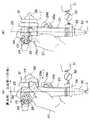
図1ないし図13は本発明の第1の実施の形態に係り、図1は第1の実施の形態を備えた内視鏡装置の全体構成を示し、図2は第1の実施の形態の内視鏡の操作部付近を把持部を把持して操作する様子を示し、図2(A)は把持部を把持して湾曲ノブを操作する様子を示し、図2(B)は把持部を把持してスイッチ群を操作する様子を示し、図3は操作部における湾曲ノブ及びスイッチ群付近を拡大して示し、図4はスイッチ群の内部構造を示し、図5はスイッチ群をエンコード回路を介して接続した構成を示し、図6はエンコード回路によるエンコードの具体例を示し、図7はエンコード回路の有無によりスイッチの数に対する接点数等を示し、図8は操作部における折れ止め部材近傍の構造を示し、図9及び図10はそれぞれ図8のA−A線及びB−B線断面を示し、図11は図8において、LCDを接続する接続装置を接続した状態の構造を示し、図12は図11のC−C線断面を示し、図13は操作部上部のマイク取付部近傍の構造を示す。
【0009】
図1に示すように内視鏡装置1は体腔内に挿入して診断等を行う内視鏡2と、この内視鏡2に照明光を供給する光源装置3と、内視鏡2に内蔵された撮像手段に対する信号処理を行う周辺装置としてのカメラコントロールユニット(以下、CCUと略記)4と、このCCU4から出力される映像信号を表示するカラーモニタ5とから構成される。
【0010】
内視鏡2は体腔内に挿入するための細長の挿入部6と、この挿入部6の後端に設けられた操作部7と、この操作部7の側部から延出されたユニバーサルケーブル(少なくともライトガイドが挿通されるので、ライトガイドケーブルとも呼ぶ)8とを有し、このユニバーサルケーブル8の末端には総合コネクタ(ライトガイドコネクタとも呼ぶ)9が設けられており、この総合コネクタ9の前端に設けたライトガイド口金11は光源装置3のコネクタ受け12に着脱自在で接続される。
【0011】
また、この総合コネクタ9の電気コネクタ受けに信号ケーブル(CCU接続ケーブルとも言う)13の一方の電気コネクタが着脱自在で接続され、他方のCCU接続に用いる電気コネクタ(CCU接続コネクタとも言う)14はCCU4の電気コネクタ受け(内視鏡接続コネクタ受けとも言う)15に着脱自在に接続される。
【0012】
上記ライトガイド口金11を光源装置3に接続することにより、光源装置3内の図示しないランプからの照明光がライトガイド口金11の端面に供給され、ユニバーサルケーブル8、操作部7、挿入部6内に挿通されたライトガイドにより照明光は伝送され、挿入部6の先端部16の照明窓に取り付けられた先端面から伝送された照明光が出射され、体腔内の患部等の対象物側を照明する。
【0013】
この照明窓に隣接して観察窓が設けられており、この観察窓に取り付けた対物レンズにより対象物の光学像をその焦点面に結ぶ。この焦点面には固体撮像素子として例えばCCD(電荷結合素子)が配置されており、光学像を光電変換する。このCCDは挿入部6内等を挿通された信号ケーブルを介して総合コネクタ9の電気コネクタ受けに接続されている。
【0014】
そして、この電気コネクタ受けにCCU接続ケーブル13の一方の電気コネクタを接続し、さらに他方のCCU接続コネクタ14をCCU4の内視鏡接続コネクタ受け15と接続することにより、CCU4内の図示しないCCDドライブ回路からドライブ信号がCCDに印加され、光電変換された信号が読み出されてCCU4内の映像信号処理回路に入力され、標準的な映像信号が生成され、この映像信号はカラーモニタ5に入力され、カラーモニタ5の表示面に対象物の像を表示する。
【0015】
挿入部6はその先端に設けられた硬質の先端部16と、この先端部16の後端に設けられ、湾曲自在の湾曲部17と、この湾曲部17の後端から操作部7の前端に至る可撓性(軟性)の可撓部18とからなる。
【0016】
湾曲部17は複数の湾曲駒を湾曲部17の長手方向に回動自在に連結されて形成され、最先端の湾曲駒或いは先端部16に一端が固定された対の湾曲用ワイヤはその他端が操作部7内に配置されたプーリ等に固定され、プーリの中心軸には湾曲ノブ21の回動軸の基端が取り付けられ、湾曲ノブ21を回動する操作を行うことによって、対となる湾曲用ワイヤの一方を牽引し(他方は弛緩される)各湾曲駒を回動させて湾曲部17全体を湾曲できるようにしている。
【0017】
操作部7はその前端側(つまり挿入部6側)に術者が把持する把持部20が設けられ、その後端側(或いは図2のように把持部20を把持した場合には上側)には湾曲操作を行う湾曲ノブ21と、画像制御を行うための円環状スイッチ部22及びその中央部の中央スイッチ部23とからなる(複数のスイッチを群にまとめた)円板形状のスイッチ群24とが設けられ、湾曲ノブ21の反対側にユニバーサルケーブル8が延出されている。
【0018】
本実施の形態では後述するように円環状スイッチ部22は円環を複数に区分けして複数のスイッチを形成し、この円環状スイッチ部22の円環中央に設けた中央スイッチ部23は単数のスイッチで形成される。
【0019】
湾曲ノブ21は湾曲部17を上下、左右にそれぞれ湾曲操作する上下湾曲ノブ35及び左右湾曲ノブ36(図3参照)を備え、図2に示すように湾曲ノブ21は挿入部6の中心軸(より厳密には挿入部6を真っ直ぐにした状態での中心軸25を操作部7側に延長したもの)25より操作部7の把持部20を把持したときの手の平と反対側(正面側 小指側)に対応する位置に設けている。
【0020】
また、挿入部6の中心軸25より把持部20を把持したときの手の平側(親指側)の側面に対応する位置に複数のスイッチを寄せ集めたスイッチ群24が配置されている。つまり、スイッチ群24は挿入部6の中心軸25を挟んで湾曲ノブ21の反対側の側面に配置されている。
【0021】
また、スイッチ群24の中心は挿入部6の中心軸25と直交する湾曲ノブ21の中心軸26より上方(挿入部6と反対側)になるように配置されている。
【0022】
そして、図2(A)に示すように手の平と薬指28d、小指28eで把持部20を把持し、湾曲ノブ2は把持部20を把持した手の親指28a、中指でそれらを回動させ、湾曲操作を行うことができるようにしている。
【0023】
なお、操作指となる親指28aの移動可能な範囲29を図2(A)の2点鎖線で示し、この範囲29はスイッチ群24の各スイッチ全域を含むし、湾曲ノブ21を親指28aで回動操作するのに必要となる部分を含む。
【0024】
湾曲操作を止め、親指28aを湾曲ノブ21から外すと、自然状態では親指28aは挿入部6の中心軸25近傍(図2(B)の2点線位置)に来て、スイッチ群24が配置された位置に来ることはないように(スイッチ群24を)配置している。
【0025】
そして、スイッチ操作を行うには、図2(B)の実線で示すように親指28aをスイッチ群24側に移動させ、所望のスイッチを操作することができる。
【0026】
従って、湾曲ノブ21より親指28a(又は人差し指)を離し、自然状態となってもスイッチ群24に触れて誤作動させてしまうことを防止或いは解消できる。
【0027】
このように本実施の形態では、操作部7には把持部20を把持した状態で、把持した手27の親指28aが自然状態で位置する中心軸25の付近にはスイッチ群24を誤作動しないようにその操作指となる親指28aを置くスペースを確保し、その両側に湾曲ノブ21とスイッチ群24を配置していることが特徴となっている。
【0028】
また、図1に示すように操作部7の前端及び挿入部6の基端の境界部分には折れ止めの機能を備えた折れ止め部材30が設けられ、この折れ止め部材30と把持部20の前端との間にはLCD31がLCD−三脚穴接続具32を介して接続或いは取り付けられるようにした接続装置33が取り付けられている。
【0029】
また、操作部7の後端(或いは図2等に示すように上部)は湾曲ノブ21よりも上側に突出し、音声入力を行うためのマイク85(図13参照)を収納したマイク取付部34が設けられている。
【0030】
図3は操作部7における湾曲ノブ21及び円板状スイッチ24付近を拡大して示し、図4はスイッチ群24の具体的な構造を示す。
図3に示すように挿入部6の中心軸25と直交する方向に突出する湾曲ノブ21は中心軸26の回りで回動自在であり、中心軸25を挟むように湾曲ノブ21と反対側には湾曲ノブ21の中心軸26よりも少し後端寄りにその中心が位置するように円板状スイッチ群24が設けられている。換言すると、湾曲ノブ21の中心軸26はスイッチ群24の中心よりも挿入部6側になるように配置されている。
【0031】
湾曲ノブ21は上下方向に湾曲する操作を行う上下湾曲ノブ35と、左右方向に湾曲する操作を行う左右湾曲ノブ36を有し、湾曲ノブ21を操作することにより湾曲部17を上下、左右の任意の方向に湾曲することができる。
【0032】
円板状スイッチ群24は円環状スイッチ部22と、このスイッチ部22の円環中央に設けられた中央スイッチ部23とを有する。円環状スイッチ部22はその周方向に複数(具体的には4個)のスイッチが設けられている。
【0033】
円環状スイッチ部22における各スイッチの境界には各スイッチの区切りを示す凸状の仕切41が設けられ、隣接する仕切41で区切られた各スイッチの中央にはスイッチであることを示す三角の突起42が設けられている。
【0034】
そして、突起42と仕切41により指で触っただけで各スイッチの位置を知ることができるようになっている。また、三角の突起42部分を押圧することにより、スイッチ操作を行うことができるようにしている。
【0035】
円環状スイッチ部22の各スイッチの具体例を説明すると、円環の上側部分にはメニュー(図面表記はMENU)、円環の下側部分にはストア(図面表記はSTR)、円環の左側にはズーム(図面表記はZM)、円環の右側には明るさ調整(図面表記はBRT)、中心には比較的使用頻度の高いフリーズ(図面表記はFRZ)のスイッチがそれぞれ設けられている。
【0036】
図4に示すように操作部7の外装部材43には円形の開口が設けられ、スイッチ群24の本体44がスイッチ外周壁45となるスイッチ固定リングによって螺合で取り付けられている。
【0037】
このスイッチ外周壁45はその周囲の操作部7の外装部材43の表面よりも外側に突出している。また、スイッチ外周壁45の突出する端面をその内側に2点鎖線で延長した高さから分かるように、突起42、仕切41を含む円環状スイッチ部22及び中央スイッチ部23よりも高くなっている。
【0038】
また、中央スイッチ部23と円環状スイッチ部22の隣接する部分の高さは中央スイッチ部23の方が高くなっており(図4ではhだけ高い)、指で触っただけで中央スイッチ部23を認識できるようになっている。そのことで、使用頻度の高い中央スイッチ部23の操作性が高くなる。
【0039】
円環状スイッチ部22の表面は円環状で突起42、仕切41を形成する薄板46で形成され、この薄板46はその下のベース部材47の上面に接着等の手段で取り付けられている。
【0040】
また、この薄板46の外径は、端面を内周側に僅かに突出させたスイッチ外周壁45の開口より若干大きくなっており、塵埃がスイッチ外周壁45の開口と薄板46の間に侵入するのを防止している。
【0041】
絶縁部材からなるベース部材47には下方に延びる4本の突棒部48(図4では2本のみ図示されている)が設けてある。また、絶縁部材からなる中央スイッチ部23にも下方に延びる突棒部49が設けてある。
【0042】
これら突棒部48、49の下端付近にはシート状のシリコンゴム等の弾性を有するゴム部材50が本体44に取り付けてあり、下方に突出する突棒部48、49に対応する位置に突棒部48、49の直径より若干小さい穴が開いており、突棒部48、49が圧入等で差し込まれ水密を確保している。
また、その他の部材とも水密の接着が施されている。また、詳細は省くが、複数のOリングを介挿し、スイッチ群24近傍は水密が確保されている。
【0043】
更に突棒部48、49の下方には若干の隙間を設けて、断面が中華鍋のように凸面形状になった変形可能な薄い導電性の金属板で形成された5個のダイアフラム51(図4では3個図示)がフレキシブル基板52の上面に配置され、このフレキシブル基板52にその下に配置した硬い板53の上に配置され、これらはその外周側を固定リング54により板53の上の周縁に配置したOリング55側に押しつけるようにして本体44に取り付けられている。
【0044】
フレキシブル基板52は円環状スイッチ部22や中央スイッチ部23の各スイッチを押すと突棒部48、49がダイアフラム51の頂部を押圧により変形させ、その下のフレキシブル基板52に設けた離間した2接点に変形したダイアフラム51が接触して通電状態となるようなパターン(回路)が形成されている。各スイッチを押すのを止めるとゴム部材50の弾性により図4の状態に復帰し、そのスイッチは非導通の状態に復帰するようになっている。
【0045】
図2(A)のように湾曲ノブ21を操作している状態から或いは図2(B)の2点鎖線で示すように湾曲ノブ21及びスイッチ群24を操作しない状態からスイッチを押す操作を行うために、親指28aをスイッチ群24の方に操作部7の外表面に沿って移動させると、スイッチ群24の周囲には突出するスイッチ外周壁45があるので、触感でスイッチ群24の位置を知ることができる。次に親指28aを所望のスイッチの上面に移動させて三角の突起42部分を押すことにより、そのスイッチをONすることができるようにしている。
【0046】
親指28aをスイッチ群24の方に移動させる際、各スイッチよりも突出するスイッチ外周壁45が各スイッチの外周に設けてあるため、誤ってスイッチを押して誤作動することを防止できる。
【0047】
なお、例えばスイッチ群24の中心から湾曲ノブ21の基端付近に沿うように親指28aを円滑に移動させることができるように両者の間の操作部7の外周面に触感で識別できるガイド部を設けるようにしても良い。そして、術者は親指28aをガイド部(例えばガイド用凸部或いはガイド用溝部)に沿って移動することにより、スイッチ群24から誤りなく、湾曲ノブ21の所定の位置に移動したり、逆に湾曲ノブ21側から誤りなくスイッチ群24の所定の位置に移動したりできるようにしても良い。
【0048】
図1で説明したように操作部7から延出されたユニバーサルケーブル8は、総合コネクタ9からCCU接続ケーブル13の端部の電気コネクタ14をCCU4の電気コネクタ受け15に着脱自在で接続される。
【0049】
図1に示すように本実施の形態ではこの総合コネクタ9内にはエンコード回路57を内蔵し、スイッチ群24の各スイッチの出力をエンコードし、このエンコード出力はCCU接続ケーブル13を介して電気コネクタ14の電気接点に接続されている。
つまり、図5に示すようにエンコード回路57はスイッチ群24とCCU接続コネクタ14に電気的に接続されている。
【0050】
具体的な接続は以下の通りである。スイッチ群24から電気ケーブルがユニバーサルケーブル8内を通り、エンコード回路57に接続され、このエンコード回路57とCCU接続コネクタ14の電気接点(ピン)とは電気ケーブルで接続されている。
【0051】
本実施の形態では5個のスイッチがあり、図5に示すようにそれぞれSW1〜5とするとエンコード回路57とスイッチ群24とはスイッチSW1〜5と+15Vの計6箇所の接続が必要になり、それらの接続に使用される電気ケーブルの数はそれと同数の6本となる。
【0052】
一方、このエンコード回路57とCCU接続コネクタ14とはSWQ0〜2の3個(3bit)のエンコード出力とエンコード回路57の駆動用の電源+15V、GNDの計5箇所の接続が必要となり、CCU接続コネクタ14内の電気接点(図5ではP1〜P5)に電気ケーブルを介してそれぞれ接続される。そのため、それらの接続に使用される電気ケーブルの数はそれと同数の5本となる。 従って、内視鏡側のCCU接続コネクタ14及びCCU側の内視鏡接続コネクタ受け15におけるスイッチ群24用の電気接点の数は5個となる。
【0053】
具体的な回路は示さないが、エンコード回路57は例えば図6に示すようにSW1〜5のON/OFF状態によりSWQ0〜2の信号出力パターンが得られるように回路設計が行われている。ここで図6中の「L」と「H」はそれぞれ「LOW」と「HIGH」を示す。
【0054】
エンコード出力の数とスイッチの関係は、エンコード出力の数をX個とするとスイッチの数は2のX乗−1個まで増やすことができ、そのときのスイッチに必要なCCU接続コネクタ14と内視鏡接続コネクタ受け15の電気接点の数はX+2(回路駆動用電源分)個となる。
【0055】
尚、今回ではスイッチの数を5個としたが、3個のエンコード出力(SWQ0〜2)を使っているので信号出力パターンは2の3乗の8通りあるため、スイッチの数は7個(どのスイッチも押されない状態が1個必要なため8−1で7)まで増やすことが出来る。
【0056】
つまり、スイッチの数が7個となっても内視鏡側のCCU接続コネクタ14、CCU側の内視鏡接続コネクタ受け15の電気接点の数は5個で済む。
また、スイッチ群24とエンコード回路57の間の電気的接続に使用される電気ケーブルの数はスイッチの数をNとするとN+1個となる。従って今回のものの電気ケーブルの数はN=5であるから6本必要となる。
【0057】
また、エンコード回路57とCCU接続コネクタ14の間の電気的接続に使用される電気ケーブルの数はエンコード出力の数をXとするとX+2個となる。従って今回のものの電気ケーブルの数はX=3であるから5本必要となる。
【0058】
一方、エンコード回路57を設けなかった場合の内視鏡側のCCU接続コネクタ14、CCU側の内視鏡接続コネクタ受け15にスイッチ群24に必要な電気接点の数はスイッチの数をNとするとN+1個必要となる。
【0059】
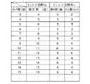
図7は以上の関係を整理して「エンコード回路57の有無によるスイッチの数とCCU接続コネクタ14の電気接点の数」を表にしたものである。図7からスイッチ数が5個以上となるとエンコード回路57がある方が、CCU接続コネクタ14の電気接点数が少なくて済むことがわかる。そのため内視鏡側のCCU接続コネクタ14及びCCU4側の内視鏡接続コネクタ受け15を小さくすることが可能である。
【0060】
具体的な回路は示さないがCCU4には各信号出力パターンを識別してデコードするデコード回路と、対応する動作を行わせる回路が設けられており、SW1〜5の任意のスイッチを押すと図6に示す何れかの信号出力パターンが発生し、CCU4でそのパターンを識別し対応する動作を行うようになっている。
【0061】
次に折れ止め部材30近傍の構造を説明する。本実施の形態では把持部20の前部側にLCD(液晶ディスプレイ)31の取付可能とするための接続装置33を取付け、接続装置33及びLCD31が把持の邪魔にならないようにすると共に、スイッチ操作等の邪魔にもならないようにしたものである。
【0062】
図8に示すように、軟性の挿入部6の後端には内周面をテーパ状にした口金62が取り付けてあり、この口金62は挿入部固定リング63を介し、操作部7の前端にある円筒形状の受け部材64に螺合で固定されている。
【0063】
この受け部材64の外周には図9に示すように、2箇所のピン65で回転位置が規制されたリング66が被さっており、このリング66の先端側は、図8及び図10に示すように外周面の例えば4箇所を切り欠いて形成した平面部66aが設けてある。
【0064】
図8に示すようにリング66は折れ止め部材30を固定する固定部材67に固定されている。この固定部材67はその後端内周に設けた雌ネジ部が受け部材64の外周にある雄ネジ部に螺合により固定されている。
【0065】
また、リング66の後端付近の外周には雄ネジ部があり、それと係合するネジ環68が取り付けられており、操作部7の外装部材いる。尚、この近傍は複数のOリングが介挿され、水密が確保された構造にしている。
【0066】
本実施の形態ではこのネジ環68を取り外して図1に示すように接続装置33を取り付けることができる。この接続装置33を取り付けた場合の構造を図11及び図12に示す。
【0067】
接続装置33はリング形状の接続装置本体71と、この接続装置本体71に嵌合し操作部7のリング66に螺合により固定するネジ環72と、この接続装置本体71に固定され、LCD−三脚穴接続具32が取り付けられる取付部材73とからなる。
【0068】
接続装置本体71の後端にはフランジが設けられ、このフランジに係合する係合凸部を前端に設けたネジ環72がその後端側の内周に設けた雌ネジでリング66の雄ネジ部に螺合により取り付けられる。
【0069】
図12に示すように接続装置本体71の前端には2つのネジ74により、取付部材73が固定されている。この取付部材73は接続装置本体71の横断面に対し、直交する方向(操作部7の長手方向)に延出するように取り付けられ、その外側の面が平面となる取付面73aを有する。
【0070】
そして、この取付面73aには三脚穴75が設けられ、図1に示したようにLCD−三脚穴接続具32を介してLCD31を接続することができる。
また、図12に示すように接続装置本体71の前端には周方向の例えば3箇所にネジ70が設けられ、リング66の平面部66aに固定することができるようにしている。
【0071】
従って、接続装置33を接続するには図8のネジ環68を回しネジ部の係合を外す。次に接続装置33を挿入部6、折れ止め部材30に通し、リング66の平面部66aと接続装置33の平面部の回転位置を合わせる。図示の例では平面部66aが90°づつずれて4箇所あるため、操作部7に対し回転位置を90°づつずらすことが可能である。
【0072】
LCD31を上に持ってきたい場合は三脚穴75が上にくるように合わせ、次にネジ環72を回し、リング66の外周の雄ネジ部とネジ環72の後端内周の雌ネジ部を係合させ接続装置33を操作部7に固定する。
【0073】
両端に三脚ネジを持つLCD−三脚穴接続具32を三脚穴75を取り付け、もう一方の三脚ネジをLCD31に取り付けることにより、図1のように設定できる。
【0074】
LCD31、接続装置33が把持部20と折れ止め部材30の間(つまり、把持部20より挿入部6側)にあるため、把持した手にそれらが干渉しないようにできると共に、湾曲操作や各種のスイッチ操作が可能となる。
【0075】
尚、当然のことながら接続装置33はLCD31を接続するばかりではなく、三脚に固定することが可能である。そうした場合、操作部7を把持しないでも観察することが可能となる。
【0076】
三脚に固定する場合、湾曲操作や各種スイッチ操作が行い易い回転位置になるように、接続装置33を取り付けることは言うまでもない。
また、操作部7の後端(上部)に設けたマイク取付部34の具体的な構造を図13に示す。
【0077】
モールド等でできた操作部7の外装を構成し、モールド等で形成された外装部材43の上面部分に設けた開口には2枚の固定板82,83がビス81等で取り付けられている。その上にはモールド等でできたマイクカバー部材84が配置され、その内側の凹部にマイク85がゴム等でできた防振部材86に囲まれた状態で固定されている。このマイク85の上方には複数の通気孔87があり、音声を拾うようになっている。
【0078】
マイク85の下方にはマイク押さえ部材88が配置され、さらにその下にはマイクカバー固定部材89が配置され、このマイクカバー固定部材89をビス90でマイクカバー84に固定することによって、マイク85、防振部材86を固定している。
【0079】
マイク85には電気ケーブル91が接続され、CCU接続コネクタ14の電気接点に接続されている。そして、このCCU接続コネクタ14が接続される内視鏡接続コネクタ受け15を介してCCU4はマイク85で発生した音声信号を受け取り、このCCU4の裏面の端子に伝送する。
【0080】
また、このマイクカバー84の内側にはOリング92、93が適宜使われ水密性を確保しながら、固定板82の下方からボルト等でマイクカバー固定部材89が接続されている。マイク85は防滴構造になっており、マイク85と防振部材86、防振部材86とマイクカバー部材84は水密接着されている。以上のようにしてマイク85近傍の防滴性が確保されている。
【0081】
マイク85で拾った音声は電気ケーブル91を通ってCCU4に至り、図示しない裏面の端子にビデオテープレコーダ等の装置が接続されていれば、記録している映像に音声をメモとしてタイムリ且つ簡単に同時記録することができるようにしている。
【0082】
上述したように本実施の形態によれば、湾曲ノブ21は挿入部6の中心軸25より操作部7の把持部20を把持したときの手の平と反対側に対応する位置に配置し、且つスイッチ群24の中心は挿入部6の中心軸25より把持部20を把持したときの手の平側の側面側に対応する位置に配置しているので、把持部20を自然に把持した状態では図2(B)の2点鎖線で示すように湾曲ノブ21とスイッチ群24との間に親指28aを置くスペースを確保し、この状態から親指28aを右側に移動すると中指とで湾曲ノブ21を回動することにより湾曲操作でき、左側に移動してスイッチ群24の位置まで移動すると所望とするスイッチの操作を行うことができるようにして、把持した片手で湾曲操作及びスイッチ操作を簡単に操作可能にすると共に、湾曲ノブ21から親指28aを離してもスイッチ群24のスイッチの誤作動させてしまうことを確実に防止できる。
【0083】
なお、第1の実施の形態では湾曲操作により、湾曲ノブ21を回動させることにより、湾曲用ワイヤを牽引/弛緩させて湾曲部17を手動で駆動するメカニカル駆動方式であるので、湾曲ノブ21に親指28aが自然状態で届く位置となっても良い。つまり、湾曲ノブ21に親指28aが自然状態で届いていても、人差し指とで回動させる操作力量を加えない限り湾曲させてしまい虞を回避できるからである(後述するように湾曲部17を電気的に駆動させる駆動装置を採用し、湾曲操作を単なるスイッチのON/OFFにした場合には親指28aが自然状態では届かない位置に設定することにより誤作動を防止できる)。
【0084】
なお、第1の実施の形態ではエンコード回路57を総合コネクタ9に設けているが、その変形例として図1の2点鎖線の符号57′で示すように操作部7内に設けるようにしても良い。
【0085】
この場合の動作は第1の実施の形態と同じとなる。
第1の実施の形態ではユニバーサルケーブル8を通るスイッチ関係の電気ケーブルはスイッチ群24からエンコード回路57の間のものであるのに対し、本変形例ではユニバーサルケーブル8を通るスイッチ関係の電気ケーブルはエンコード回路57′からCCU接続コネクタ14に接続されるものとなる。今回示したものではその本数は第1の実施の形態における6本から5本に削減できる。
【0086】
以上のように、操作部7内にエンコード回路57′を設けることでユニバーサルケーブル8内を通す電気ケーブルの本数を減らすことが可能である。一般的にユニバーサルケーブル8は操作性を考えると柔軟な方が良い。電気ケーブルの本数を減らすことが可能なため、ユニバーサルケーブル8を細くして柔軟にすることが可能となり、その結果操作性を向上させることができるという効果を有する。
【0087】
なお、本実施の形態では術者は左の手27で把持部20を把持してその手の親指28aでスイッチ群24を操作し易いように湾曲ノブ21及びスイッチ群24を配置したが、右の手で把持して操作する術者のために、図2におけるスイッチ群24が設けられた左側面の反対側の右側面で、同じ位置にスイッチ群24を設ける(図2で実線のスイッチ群24を破線にした位置)ようにしていも良い。
【0088】
また、本実施の形態では親指28aを操作指としてスイッチ群24を操作するタイプについて説明したが、人差し指で操作する場合には操作部7における図2のスイッチ群24の反対側の右側面に設けるようにしても良い。
【0089】
(第2の実施の形態)
図14は本発明の第2の実施の形態の内視鏡2Bにおける操作部7周辺を示す。本実施の形態では図14に示すように第1の実施の形態と同じスイッチ群24が湾曲ノブ21側から見た場合の操作部7の左の側面に設けられている他に、この操作部7の右の側面にもスイッチ群24と同じ構造のスイッチ群24′が設けてある。
【0090】
つまり、操作部7は挿入部6の中心軸25に対して左右対称形であり、かつ左右対称な位置に2組の同じスイッチ群24、24′が設けてある。
従って、本実施の形態では例えばスイッチ群24を正面となるように左側面側から見た場合には第1の実施の形態と同じ位置に一方のスイッチ群24が位置し、その場合の裏面となる右側面には他方のスイッチ群24′が位置することになる。
【0091】
その他の構成は第1の実施の形態と同様の構成であり、同じ部材には同じ符号を付けてその説明を省略する。
この様な構成にすることにより、左右どちらの手で把持しても片手操作で第1の実施の形態と同様の操作を行うことができるし、スイッチの誤作動なども防止できる。
【0092】
(第3の実施の形態)
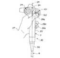
図15は本発明の第3の実施の形態の内視鏡2Cにおける操作部7の周辺を示す。本実施の形態ではスイッチ群24の配置は第1の実施の形態と同じであり、電気的に湾曲部17を駆動する電動式湾曲駆動装置を採用している。
【0093】
従って、メカニカルに湾曲駆動操作する湾曲ノブ21の代わりに円板状の湾曲スイッチ群101が操作部7の側面に設けてある。また、操作部7内には図示しないモータ等の湾曲用ワイヤを電気的に駆動する動力装置を備え、湾曲スイッチ群101は上下左右の4方向の湾曲操作を行う4種のスイッチと湾曲の固定・解除を行うスイッチとが円環の周方向及び円環の中央に配置されて群となったものである。
【0094】
本実施の形態では円環の上側部分(図面表記はU)には湾曲方向、円環部分の下側には湾曲下方向、円環部分の左側(図面表記はL)には湾曲左方向、円環部分の右側(図面表記はR)には湾曲右方向、円環の中央には湾曲の固定(図面表記はF)の各スイッチが設けられている。
【0095】
図15に示すようにスイッチ群24を正面に見た左側面図では挿入部6の中心軸25に対し、その左側にはスイッチ群24、右側には湾曲スイッチ群101が配置されている。
【0096】
換言すると、中心軸25を挟んでスイッチ群24の反対側(正面側或いは図15で中心軸25の右側)に湾曲スイッチ群101が配置されている。また、湾曲スイッチ群101の中心を通る中心軸102は挿入部6の中心軸25と直交し、かつスイッチ群24の中心より挿入部6側(図15では下側)にある。
【0097】
湾曲を操作するときは親指28aを湾曲スイッチ群101の適宜位置に移動して行い、スイッチ操作をするときは親指28aをスイッチ群24側に移動して操作しようとするスイッチを押圧する。
【0098】
このように本実施の形態では把持部20を手で把持した場合、その手の親指の自然状態で位置する中心軸25付近を避けてその両側にスイッチ群24及び湾曲スイッチ群101を配置(勿論親指が届く範囲内)し、把持した片手でいずれのスイッチも操作可能にすると共に、自然状態ではいずれのスイッチに触れてしまうことがなく、誤作動させないようにしている。
なお、湾曲スイッチ群101の構造は例えばスイッチ群24と同じ構造にしても良い。
【0099】
また、本実施の形態では図16に示すように操作部7の外装部材43で囲まれた内側には湾曲操作及び湾曲駆動等に必要な種々の部品を取り付けるための取付板112を配置している。この場合、以下に説明するように操作部7内の電気基板の短絡等を防止して電気基板を取り付ける構造にしている。
【0100】
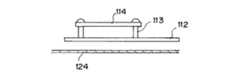
図17に示すように取付板112の一方には湾曲操作用に必要な複数の湾曲用ワイヤ124が通っており、取付板112を挟んで反対側の上面に電気絶縁性のある足113を介し、隙間をあけてエンコード回路等の電気基板114がビス115を使って固定されている。
【0101】
電気基板114から複数の電気ケーブル116が出ている。また、電気基板114には電気ケーブル束やフレキシブル基板と電気的接続、取り外しを容易にするためのコネクタ117が設けてある。
【0102】
複数の電気ケーブルをシート状の束にしたケーブル束118の一端はスイッチ群24のフレキシブル基板と電気的に接続され、操作部7で適宜折り畳まれており、もう一方の端がコネクタ117に電気的に接続されている。
尚、ケーブル束118を使わないで、フレキシブル基板が適宜折り畳まれ、直接接続されていても良い。
【0103】
ライトガイド119や撮像手段を形成するCCDからの信号ケーブル120は湾曲用ワイヤ124の移動が引っかかることがないように取付板112を挟んで湾曲用ワイヤ124と反対側、つまり電気基板114が取り付けた側を通っている。
【0104】
CCDからの信号ケーブル120は電気ノイズの影響を受けないようにするために導電性のあるシールドが被覆されている。図18に示すような電気絶縁シート121を点線で示す部分で「コの字状」に折曲げ、取付板112にビス122を使って固定されている。ライトガイド119やCCDからの信号ケーブル120は電気絶縁シート121で移動可能な位置が規制され、電気基板114上に移動しない規制手段が形成されるようになっている。
【0105】
図18に示すように電気絶縁シート121には切り欠き123が設けてあり、図16に示すようにケーブル束118はその部分を通ってコネクタ117に接続されている。
【0106】
本実施の形態では湾曲駆動を行うのにモータ等の電気的駆動装置を使用しているため、余り大きな力量で操作を行う必要がない効果がある。また、把持した手の自然状態の親指が位置する付近の右側に湾曲スイッチ群101を配置しているので、誤って湾曲スイッチを作動させてしまうことを防止できる。その他は第1の実施の形態と同様の効果がある。
【0107】
なお、上記実施の形態では電気絶縁シート121による規制手段を操作部7内に設けてライトガイド119、信号ケーブル120が電気基板114上に移動しないようにして、電気基板114に実装された部品や、パターンを損傷させること等を防止しているが、電気基板が操作部7以外の内視鏡内(例えば図1の総合コネクタ9、CCU接続コネクタ14)に設けられた場合にも適用できる。
【0108】
なお、図14に示す第2の実施の形態と同様に、正面から見て挿入部6の中心軸25に関し左右対称となるようにスイッチ群24、24′と湾曲スイッチ群101、101′を2組づつ設けるようにしても良い。このようにすると、湾曲駆動を電気的に行う構造にした場合の湾曲操作装置となる湾曲スイッチ群101、101′の操作を左右の手のいずれで把持して操作する場合にも、良好な湾曲操作を軽い湾曲操作で行うことができる。勿論、スイッチ操作も左右の手のいずれで把持した場合にも良好な操作ができる。
【0109】
図14に示す第2の実施の形態と同様に、正面から見て挿入部6の中心軸25と対称となるようにスイッチ群24、24′の他に湾曲スイッチ群101、101′を2組づつ設けるようにしても良い。このようにすると、湾曲駆動を電気的に行う構造にした場合の湾曲操作装置となる湾曲スイッチ群の操作を左右の手のいずれで把持して操作する場合にも、良好な湾曲操作を軽い湾曲操作で行うことができる。
【0110】
尚、電気絶縁シートは折曲げ可能な部材であったが、電気絶縁性のあるものであればどんなものでも良い。また、今回は電気基板が操作部内にある場合について記載したが、CCUコネクタ内にあっても同様である。
【0111】
なお、本発明は撮像手段を内蔵しないで、光学像を伝送するイメージガイドを備えた内視鏡の場合にも適用できる。
なお、上述した実施の形態等を部分的等で組み合わせて構成される実施の形態等も本発明に属する。
【0112】
[付記]
1.操作部に湾曲操作を行う湾曲操作装置と複数のスイッチを寄せて群としたスイッチ群とを有する内視鏡において、
湾曲操作装置は挿入部の中心軸より操作部を把持したときの手の平と反対側に対応する位置に配置し、且つスイッチ群の中心は挿入部の中心軸より操作部を把持したときの手の平側の側面側に対応する位置に配置したことを特徴とする内視鏡。
(付記1の効果)
湾曲操作や各種のスイッチ操作を含めた片手操作が行い易く、且つ湾曲ノブから親指を離しても、誤ってスイッチに触れて誤作動することがない。
【0113】
2.挿入部の中心軸と直交する湾曲操作装置の中心軸が、挿入部の中心軸と直交するスイッチ群の中心より挿入部側にあることを特徴とする付記1記載の内視鏡。
【0114】
3.操作部にスイッチを設けた内視鏡において、
前記スイッチを操作する操作面の周りに、その操作面より高い壁部を設けた内視鏡。
(付記3の背景)
特開昭63−280213号公報では操作部の面より出っ張ったスイッチが取り付けられている。この場合、スイッチは押し易いが、逆に誤って押して誤作動させるという問題があった。
【0115】
(付記3の目的)
スイッチが押し易く、且つ誤ってスイッチを押してしまい誤作動することがないスイッチを有する内視鏡の提供。この目的を達成するために付記3の構成にした。
(付記3の効果)
スイッチが押し易く、且つ誤ってスイッチを押してしまい誤作動することがない。
【0116】
4.複数のスイッチと周辺装置に接続する周辺装置接続コネクタの間に電気的に接続されたエンコード回路を設け、前記エンコード回路は各スイッチの出力をエンコードして対応する信号パターンを出力し、周辺装置は各信号出力パターンを識別し、作動させる回路を有する内視鏡装置。
【0117】
(付記4の背景)
CCU(カメラコントロールユニット)や画像処理装置等の周辺装置にあるスイッチを操作部にも設けると操作性が向上する。しかし、その場合、内視鏡とCCU等の周辺装置を電気的に接続する内視鏡側、周辺装置側何れのコネクタも電気接点(ピン)の数が多くなり、大きくなってしまうという問題があった。
【0118】
(付記4の目的)
内視鏡側のスイッチを増やしても、周辺装置接続コネクタの電気接点(ピン)の数を余り増やさず、内視鏡側、周辺装置側のコネクタがあまり大きくならない内視鏡装置の提供。この目的を達成するために付記4の構成にした。
(付記4の効果)
内視鏡側のスイッチを増やしても、周辺装置接続コネクタの電気接点(ピン)の数を余り増やさず、内視鏡側、周辺装置側のコネクタがあまり大きくならないようにできる。
【0119】
5. 操作部における把持部より挿入部側の位置にLCDを固定する接続装置を取り付け可能とする取付部を設けた内視鏡。
(付記5の背景)
TVモニタを使って検査する場合、LCDを操作部に付けて検査すると検査装置が小型化して、運搬や設置が容易になる。特開平7−031580号公報では操作部にLCDの保持部を設け、LCDが着脱可能なものが開示されている。
しかし、取り付けた接続部やLCDが邪魔になって操作部を把持できないため、片手で操作部を把持した状態で湾曲操作や各種スイッチの操作がし難いという問題があった。
【0120】
(付記5の目的)
操作部にLCDを取り付けても操作部を把持でき、把持した手で湾曲操作や各種のスイッチ操作がLCDが邪魔になることなく行える内視鏡の提供。この目的を達成するために付記5の構成にした。
(付記5の効果)
操作部にLCDを取り付けても操作部を把持でき、把持した手で湾曲操作や各種のスイッチ操作がLCDが邪魔になることなく行える。
【0121】
6. 撮像手段を備えた内視鏡において、
操作部や総合コネクタや周辺装置接続コネクタ内にある電気基板の近傍に電気絶縁部材を設け、前記電気絶縁部材により信号ケーブルが電気基板上に移動しないように規制する規制手段を設けた内視鏡。
(付記6の背景)
撮像手段を内蔵した内視鏡の操作部や総合コネクタやCCU等の周辺装置に接続するCCU接続コネクタ(周辺装置接続コネクタ)内にはCCDから出た信号ケーブルが通っている。その信号ケーブルには電気ノイズの影響を受けないようにするため電気シールドが被覆されている。
操作部や総合コネクタやCCU接続コネクタ内に電気基板を設けた場合、振動で信号ケーブルが移動して電気基板の活電部に触れ、電気シールドを介し、短絡して誤動作や電気基板やその他の破壊を招くという問題があった。
【0122】
(付記6の目的)
操作部や総合コネクタやCCU接続コネクタ内に電気基板を設けた場合、振動で信号ケーブルが移動して電気基板の活電部に触れ、電気シールドを介し、短絡して誤動作や電気基板やその他の破壊を招くことがない内視鏡の提供。この目的を達成するために付記6の構成にした。
(付記6の効果)
操作部や総合コネクタや周辺装置接続コネクタ内に電気基板を設けた場合、振動で信号ケーブルが移動して電気基板の活電部に触れ、信号ケーブルを被覆する電気シールドを介し、短絡して誤動作や電気基板やその他の破壊を招くことを防止できる。
【0123】
7.挿入部の後端の操作部にマイクを設けた内視鏡において、
マイクの周りを防振材で囲み、固定したことを特徴とする内視鏡。
(付記7の背景)
音声を入力しながら内視鏡検査をするとき、マイクを操作部に設けると非常に便利であり、特開平6−178756では内視鏡の操作部にマイクを設けたものが示されている。しかし、操作部をぶつけて発生するノイズや湾曲操作を行ったりして発生するノイズ等を拾ったりするという問題があった。
【0124】
(付記7の目的)
このため、操作部に設けたマイクがノイズを拾わないようにできる内視鏡の提供。この目的を達成するために付記7の構成にして、防振材によりマイクがノイズを拾わないようにした。
(付記7の効果)
操作部をぶつけて発生するノイズや湾曲操作を行ったりして発生するノイズ等を防振材で吸収し、マイクがノイズとして拾うことを解消できる。
【0125】
【発明の効果】
以上説明したように本発明によれば、操作部を把持して親指を動かさない状態では、親指が親指載置スペースに位置していてスイッチ群の各スイッチ、及び湾曲操作装置に触れることがないので、誤操作を防止でき、また前記親指を移動させることによって前記スイッチ及び湾曲操作装置を操作できるので操作性が良好であるといった効果を有する。
【図面の簡単な説明】
【図1】本発明の第1の実施の形態を備えた内視鏡装置の全体構成図。
【図2】第1の実施の形態の内視鏡の操作部付近を把持部を把持して湾曲ノブを操作する状態とスイッチ群を操作する状態を示す側面図。
【図3】操作部における湾曲ノブとスイッチ群周辺を拡大して示す側面図。
【図4】スイッチ群の内部構造を示す断面図。
【図5】スイッチ群の出力をエンコード回路でエンコードしてCCU接続コネクタに伝送する構成を示す図。
【図6】エンコード回路でスイッチ群の出力をエンコードする具体例を示す図。
【図7】エンコード回路の有無によりスイッチの数に対する接点数等の関係を示す図。
【図8】操作部における折れ止め部材近傍の構造を示す断面図。
【図9】図8のA−A線断面図。
【図10】図8のB−B線断面図。
【図11】図8において、接続装置を取り付けた構造を示す断面図。
【図12】図11のC−C線断面図。
【図13】操作部上部のマイク取付部近傍の構造を示す断面図。
【図14】本発明の第2の実施の形態の内視鏡の操作部付近を示す正面図。
【図15】本発明の第3の実施の形態の内視鏡の操作部付近を示す正面図。
【図16】操作部内に配置された湾曲操作の制御回路等を取り付けた取付板付近を示す平面図。
【図17】図16の側方から見た場合にその下側に湾曲用ワイヤが配置される様子を示す図。
【図18】折り曲げる前の電気絶縁シートを示す展開図。
【符号の説明】
1…内視鏡装置
2…内視鏡
3…光源装置
4…CCU
5…カラーモニタ
6…挿入部
7…操作部
8…ユニバーサルケーブル
9…総合コネクタ
13…CCU接続ケーブル
14…CCU接続コネクタ
20…把持部
21…湾曲ノブ
22…円環状スイッチ部
23…中央スイッチ
24…スイッチ群
25、26…中心軸
27…手
28a…親指
30…折れ止め部材
34…マイク取付部
41…仕切
42…突起
57…エンコード回路[0001]
BACKGROUND OF THE INVENTION
The present invention relates to an endoscope in which a switch group including a plurality of switches is provided in an operation unit.
[0002]
[Prior art]
In recent years, endoscopes having an elongated insertion portion and provided with illumination means and observation means at the distal end thereof have been widely used in the medical field and the industrial field. In particular, in an endoscope having a flexible insertion portion, a bending portion is provided on the distal end side of the insertion portion and provided at the rear end of the insertion portion so that the insertion portion can be smoothly inserted into a bent body cavity or the like. The bending portion can be bent by operating a bending knob or the like as a bending operation device that performs a bending operation on the operation portion held by the.
[0003]
Further, in an electronic endoscope provided with an imaging means, a plurality of switches are provided in an operation unit for image control, and in order to make these operations easy with one hand, Japanese Patent Application Laid-Open No. 6-142030. In this endoscope, a plurality of switches are grouped, and these switch groups are provided near the central axis of the insertion portion on the side surface of the operation portion.
[0004]
Only when a plurality of reflected light detectors are positioned on each switch surface and three or more of these reflected light detectors detect reflected light with a predetermined range of reflectance, the operation function assigned to that switch surface is It is made to operate by the limited reflection type photo reflector to be operated.
[0005]
[Problems to be solved by the invention]
However, when the operation unit is gripped with the palm, the ring finger, and the little finger, the thumb comes to the vicinity of the bending knob or the central axis of the insertion unit in a natural state. For this reason, when the thumb is released from the bending knob, the thumb easily touches the switch surface forming the switch group, which may cause malfunction.
[0006]
(Object of invention)
The present invention has been made in view of the above points, and is easy to perform a one-hand operation including a bending operation and a switch operation, and when the thumb is released from the bending operation device, the switch is not touched to cause a malfunction. An object is to provide an endoscope.
[0007]
[Means for Solving the Problems]
In order to achieve the above object, an endoscope according to one aspect of the present invention includes a bending portion and a distal end portion on a distal end side of an elongated insertion portion, and an operation portion provided on a rear end side.
A thumb placement space provided on the operation surface in the vicinity of the central axis of the operation unit;
A bending operation device that performs a bending operation of the bending portion provided on one side with respect to the thumb placement space;
The position opposite to the position of the bending operation device on the other side with respect to the thumb placement space, the center of which is above the central axis of the bending operation device orthogonal to the central axis of the operation unit A switch group in which a plurality of switches are arranged in an annular shape,
A wall portion provided on the outer peripheral side of the switch group in which the switches are arranged in an annular shape and projecting from the operation surface of the operation portion;
With
In a state where the operation unit is gripped with a palm, a ring finger, and a little finger,
The thumb placement space is arranged at a position where the thumb is placed without moving,
The bending operation device and the switch group are arranged at positions where the thumb can be operated when the thumb is moved.
[0008]
DETAILED DESCRIPTION OF THE INVENTION
Embodiments of the present invention will be described below with reference to the drawings.
(First embodiment)
FIGS. 1 to 13 relate to a first embodiment of the present invention, FIG. 1 shows an overall configuration of an endoscope apparatus including the first embodiment, and FIG. 2 shows the first embodiment. FIG. 2 (A) shows a state where a gripping part is gripped and operated near the operation part of the endoscope, FIG. 2 (A) shows a state where a gripping part is operated and a bending knob is operated, and FIG. 2 (B) shows a gripping part. FIG. 3 shows an enlarged view of the bending knob and the vicinity of the switch group in the operation unit, FIG. 4 shows the internal structure of the switch group, and FIG. 5 shows an encoding circuit for the switch group. 6 shows a specific example of encoding by the encoding circuit, FIG. 7 shows the number of contacts with respect to the number of switches depending on the presence or absence of the encoding circuit, and FIG. 8 shows the vicinity of the folding prevention member in the operation unit. FIG. 9 and FIG. 10 show the structure of FIG. 11 shows a cross section taken along the line BB, FIG. 11 shows the structure in the state where the connecting device for connecting the LCD is connected in FIG. 8, FIG. 12 shows the cross section taken along the line CC in FIG. The structure near the microphone mounting part at the top of the part is shown.
[0009]
As shown in FIG. 1, an
[0010]
The
[0011]
In addition, one electrical connector of a signal cable (also referred to as CCU connection cable) 13 is detachably connected to the electrical connector receptacle of the
[0012]
By connecting the
[0013]
An observation window is provided adjacent to the illumination window, and an optical image of the object is connected to the focal plane by an objective lens attached to the observation window. On this focal plane, for example, a CCD (charge coupled device) is disposed as a solid-state imaging device, and photoelectrically converts the optical image. This CCD is connected to the electrical connector receptacle of the
[0014]
Then, one electrical connector of the
[0015]
The
[0016]
The bending
[0017]
The
[0018]
In this embodiment, as will be described later, the
[0019]
The bending
[0020]
In addition, a
[0021]
The center of the
[0022]
Then, as shown in FIG. 2A, the
[0023]
Note that a
[0024]
When the bending operation is stopped and the
[0025]
In order to perform the switch operation, a desired switch can be operated by moving the
[0026]
Accordingly, it is possible to prevent or eliminate the erroneous operation by touching the
[0027]
As described above, in the present embodiment, the
[0028]
Further, as shown in FIG. 1, a
[0029]
Further, the rear end (or the upper part as shown in FIG. 2 and the like) of the
[0030]
FIG. 3 shows an enlarged view of the vicinity of the bending
As shown in FIG. 3, the bending
[0031]
The bending
[0032]
The disk-
[0033]
A
[0034]
And the position of each switch can be known just by touching with the finger by the
[0035]
A specific example of each switch of the
[0036]
As shown in FIG. 4, a circular opening is provided in the
[0037]
The switch outer
[0038]
Further, the height of the adjacent portions of the
[0039]
The surface of the
[0040]
Further, the outer diameter of the
[0041]
The
[0042]
A
Further, watertight adhesion is applied to other members. Although details are omitted, a plurality of O-rings are inserted, and the vicinity of the
[0043]
Further, five diaphragms 51 (Fig. 5) are formed of a deformable thin conductive metal plate with a slight gap provided below the projecting
[0044]
When the
[0045]
The operation of pressing the switch is performed from the state where the bending
[0046]
When the
[0047]
For example, a guide portion that can be identified by tactile sensation on the outer peripheral surface of the
[0048]
As described with reference to FIG. 1, the
[0049]
As shown in FIG. 1, in this embodiment, an
That is, as shown in FIG. 5, the
[0050]
The specific connection is as follows. An electrical cable from the
[0051]
In the present embodiment, there are five switches. As shown in FIG. 5, when SW1 to SW5 are used, the
[0052]
On the other hand, the
[0053]
Although a specific circuit is not shown, the
[0054]
The relationship between the number of encode outputs and the switches is that if the number of encode outputs is X, the number of switches can be increased to 2 to the power of X-1 and the
[0055]
In this example, the number of switches is 5. However, since 3 encode outputs (SWQ0 to 2) are used, there are 8 signal output patterns of 2 to the 3rd power, so the number of switches is 7 ( Since one switch is not pressed, it can be increased to 7) in 8-1.
[0056]
That is, even if the number of switches is seven, only five electrical contacts are required for the
The number of electrical cables used for electrical connection between the
[0057]
The number of electrical cables used for electrical connection between the encode
[0058]
On the other hand, when the
[0059]
FIG. 7 is a table in which “the number of switches depending on the presence / absence of the
[0060]
Although a specific circuit is not shown, the
[0061]
Next, the structure near the folding
[0062]
As shown in FIG. 8, a
[0063]
As shown in FIG. 9, a
[0064]
As shown in FIG. 8, the
[0065]
The outer periphery of the
[0066]
In the present embodiment, the
[0067]
The
[0068]
A flange is provided at the rear end of the connecting device
[0069]
As shown in FIG. 12, the
[0070]
The mounting
Also, as shown in FIG. 12, screws 70 are provided at, for example, three locations in the circumferential direction at the front end of the connection device
[0071]
Accordingly, to connect the connecting
[0072]
If you want to bring the
[0073]
By attaching the
[0074]
Since the
[0075]
As a matter of course, the
[0076]
Needless to say, when fixing to a tripod, the connecting
FIG. 13 shows a specific structure of the
[0077]
Two fixing
[0078]
A
[0079]
An
[0080]
Further, inside the
[0081]
The sound picked up by the
[0082]
As described above, according to the present embodiment, the bending
[0083]
In the first embodiment, since the bending
[0084]
In the first embodiment, the
[0085]
The operation in this case is the same as that of the first embodiment.
In the first embodiment, the switch-related electric cable passing through the
[0086]
As described above, by providing the
[0087]
In this embodiment, the surgeon holds the
[0088]
Further, in the present embodiment, the type in which the
[0089]
(Second Embodiment)
FIG. 14 shows the periphery of the
[0090]
That is, the
Therefore, in the present embodiment, for example, when the
[0091]
Other configurations are the same as those of the first embodiment, and the same members are denoted by the same reference numerals and the description thereof is omitted.
By adopting such a configuration, the same operation as that of the first embodiment can be performed by one-hand operation regardless of whether the hand is held by either the left or right hand, and malfunction of the switch can be prevented.
[0092]
(Third embodiment)
FIG. 15 shows the periphery of the
[0093]
Therefore, a disk-shaped
[0094]
In the present embodiment, the upper part of the ring (the drawing notation is U) is the bending direction, the lower part of the annular part is the bending downward direction, the left side of the annular part (the drawing notation is L) is the bending left direction, On the right side (R in the drawing) of the ring portion, there are switches for the right direction of the curve, and in the center of the ring, a switch for fixing the curve (F in the drawing).
[0095]
As shown in FIG. 15, in the left side view when the
[0096]
In other words, the bending
[0097]
When the bending is operated, the
[0098]
As described above, in the present embodiment, when the
The bending
[0099]
Further, in the present embodiment, as shown in FIG. 16, an
[0100]
As shown in FIG. 17, a plurality of bending
[0101]
A plurality of
[0102]
One end of a
Note that the flexible substrate may be appropriately folded and directly connected without using the
[0103]
The
[0104]
The
[0105]
As shown in FIG. 18, the
[0106]
In this embodiment, since an electric drive device such as a motor is used to perform the bending drive, there is an effect that it is not necessary to perform an operation with an excessively large force. In addition, since the bending
[0107]
In the above-described embodiment, the control means by the electric insulating
[0108]
As in the second embodiment shown in FIG. 14, two
[0109]
As in the second embodiment shown in FIG. 14, two sets of bending
[0110]
The electrical insulating sheet is a foldable member, but any material having electrical insulation properties may be used. In addition, the case where the electric board is in the operation unit has been described this time, but the same applies to the case in the CCU connector.
[0111]
Note that the present invention can also be applied to an endoscope provided with an image guide for transmitting an optical image without incorporating an imaging means.
Note that embodiments and the like configured by partially combining the above-described embodiments and the like also belong to the present invention.
[0112]
[Appendix]
1. In an endoscope having a bending operation device that performs a bending operation on an operation unit and a switch group in which a plurality of switches are brought together,
The bending operation device is arranged at a position corresponding to the opposite side of the palm when the operation unit is gripped from the central axis of the insertion unit, and the center of the switch group is the palm side when the operation unit is gripped from the central axis of the insertion unit An endoscope characterized in that it is arranged at a position corresponding to the side surface of the endoscope.
(Effects of Appendix 1)
One-handed operation including bending operation and various switch operations is easy to perform, and even if the thumb is removed from the bending knob, the switch is not touched by mistake and malfunctions are not caused.
[0113]
2. The endoscope according to
[0114]
3. In an endoscope provided with a switch in the operation unit,
The endoscope which provided the wall part higher than the operation surface around the operation surface which operates the said switch.
(Background to Appendix 3)
In Japanese Patent Laid-Open No. 63-280213, a switch protruding from the surface of the operation unit is attached. In this case, the switch is easy to push, but there is a problem that it is erroneously pushed to make it malfunction.
[0115]
(Purpose of Appendix 3)
Provided is an endoscope having a switch that is easy to press and does not malfunction because the switch is accidentally pressed. In order to achieve this purpose, the configuration of
(Effects of Appendix 3)
The switch is easy to push and does not malfunction because the switch is pushed by mistake.
[0116]
4). An encoding circuit electrically connected is provided between a plurality of switches and a peripheral device connection connector connected to the peripheral device, and the encoding circuit encodes an output of each switch and outputs a corresponding signal pattern. An endoscope apparatus having a circuit for identifying and operating each signal output pattern.
[0117]
(Background of Appendix 4)
If a switch in a peripheral device such as a CCU (camera control unit) or an image processing device is also provided in the operation unit, the operability is improved. However, in that case, there is a problem that the number of electrical contacts (pins) increases in both the endoscope-side and peripheral-device-side connectors that electrically connect the endoscope and peripheral devices such as the CCU. there were.
[0118]
(Purpose of Appendix 4)
Providing an endoscope apparatus in which the number of electrical contacts (pins) of a peripheral device connection connector does not increase so much even if the number of switches on the endoscope side is increased, and the connectors on the endoscope side and the peripheral device side do not become too large. In order to achieve this object, the configuration of
(Effects of Appendix 4)
Even if the number of switches on the endoscope side is increased, the number of electrical contacts (pins) of the peripheral device connection connector is not increased so much that the connectors on the endoscope side and the peripheral device side can be prevented from becoming too large.
[0119]
5). An endoscope provided with an attachment portion that enables attachment of a connection device that fixes the LCD at a position closer to the insertion portion than the grip portion in the operation portion.
(Background to Appendix 5)
When inspecting using a TV monitor, if the inspection is performed with the LCD attached to the operation unit, the inspection apparatus is reduced in size and is easy to transport and install. Japanese Patent Application Laid-Open No. 7-031580 discloses a device in which a LCD holding portion is provided in the operation portion and the LCD is detachable.
However, there is a problem in that it is difficult to perform a bending operation and various switch operations while holding the operation unit with one hand because the attached connection unit or LCD is in the way and cannot hold the operation unit.
[0120]
(Purpose of Appendix 5)
Providing an endoscope in which an operation unit can be gripped even if an LCD is attached to the operation unit, and a bending operation and various switch operations can be performed without obstructing the LCD with the gripped hand. In order to achieve this object, the configuration of
(Effects of Appendix 5)
Even if an LCD is attached to the operation unit, the operation unit can be grasped, and the bending operation and various switch operations can be performed without obstructing the LCD with the grasped hand.
[0121]
6). In an endoscope provided with imaging means,
An endoscope provided with an electric insulating member in the vicinity of an electric board in an operation unit, a general connector, or a peripheral device connecting connector, and provided with a regulating means for restricting the signal cable from moving on the electric board by the electric insulating member. .
(Background to Appendix 6)
A signal cable from the CCD passes through a CCU connection connector (peripheral device connection connector) connected to a peripheral device such as an operation unit of the endoscope incorporating the imaging means, a general connector, or a CCU. The signal cable is covered with an electric shield so as not to be affected by electric noise.
When an electric board is provided in the operation unit, general connector, or CCU connector, the signal cable is moved by vibration and touches the live part of the electric board. There was a problem of causing destruction.
[0122]
(Purpose of Appendix 6)
When an electric board is provided in the operation unit, general connector, or CCU connector, the signal cable is moved by vibration and touches the live part of the electric board. Providing an endoscope that does not cause destruction. In order to achieve this object, the configuration of
(Effects of Appendix 6)
When an electric board is installed in the operation unit, general connector, or peripheral device connection connector, the signal cable moves due to vibration, touches the live part of the electric board, and malfunctions due to a short circuit through the electric shield that covers the signal cable. In addition, it is possible to prevent the electric substrate and other parts from being destroyed.
[0123]
7). In an endoscope provided with a microphone in the operation part at the rear end of the insertion part,
An endoscope characterized in that the microphone is surrounded by a vibration-proof material and fixed.
(Background to Appendix 7)
When performing an endoscopic examination while inputting voice, it is very convenient to provide a microphone in the operation unit. Japanese Patent Application Laid-Open No. 6-178756 discloses a method in which a microphone is provided in the operation unit of the endoscope. However, there has been a problem of picking up noise generated by hitting the operation unit, noise generated by performing a bending operation, and the like.
[0124]
(Purpose of Appendix 7)
For this reason, the provision of the endoscope which can prevent the microphone provided in the operation unit from picking up noise. In order to achieve this purpose, the microphone is prevented from picking up noise by using the vibration isolating material in the configuration of
(Effects of Appendix 7)
Noise generated by hitting the operation unit, noise generated by performing a bending operation, etc. can be absorbed by the vibration isolator, and the microphone can be prevented from picking up as noise.
[0125]
【The invention's effect】
As described above, according to the present invention, in a state where the operation unit is gripped and the thumb is not moved, the thumb is positioned in the thumb placement space and does not touch each switch of the switch group and the bending operation device. Therefore, an erroneous operation can be prevented, and the switch and the bending operation device can be operated by moving the thumb, so that the operability is good.Has an effect.
[Brief description of the drawings]
FIG. 1 is an overall configuration diagram of an endoscope apparatus provided with a first embodiment of the present invention.
FIGS. 2A and 2B are side views showing a state in which the grip knob is gripped near the operating portion of the endoscope according to the first embodiment and a bending knob is operated and a switch group is operated.
FIG. 3 is an enlarged side view showing the bending knob and the vicinity of a switch group in the operation unit.
FIG. 4 is a sectional view showing an internal structure of a switch group.
FIG. 5 is a diagram showing a configuration in which an output of a switch group is encoded by an encoding circuit and transmitted to a CCU connector.
FIG. 6 is a diagram showing a specific example in which the output of the switch group is encoded by the encoding circuit.
FIG. 7 is a diagram showing the relationship between the number of contacts and the number of switches depending on the presence or absence of an encoding circuit.
FIG. 8 is a cross-sectional view showing a structure in the vicinity of a bend preventing member in an operation unit.
9 is a cross-sectional view taken along line AA in FIG.
10 is a sectional view taken along line BB in FIG.
11 is a cross-sectional view showing a structure in which a connection device is attached in FIG.
12 is a cross-sectional view taken along line CC in FIG.
FIG. 13 is a cross-sectional view showing a structure in the vicinity of the microphone mounting portion at the top of the operation portion.
FIG. 14 is a front view showing the vicinity of an operation unit of an endoscope according to a second embodiment of the present invention.
FIG. 15 is a front view showing the vicinity of an operation unit of an endoscope according to a third embodiment of the present invention.
FIG. 16 is a plan view showing the vicinity of a mounting plate on which a control circuit or the like for bending operation disposed in the operation unit is mounted.
17 is a view showing a state in which a bending wire is arranged on the lower side when viewed from the side of FIG. 16;
FIG. 18 is a development view showing the electrical insulating sheet before being bent.
[Explanation of symbols]
1. Endoscope device
2. Endoscope
3. Light source device
4 ... CCU
5. Color monitor
6 ... Insertion section
7. Operation unit
8 ... Universal cable
9 ... General connector
13 ... CCU connection cable
14 ... CCU connector
20 ... gripping part
21 ... Curving knob
22 ... Annular switch
23 ... Center switch
24 ... Switch group
25, 26 ... central axis
27 ... hand
28a ... thumb
30 ... Folding prevention member
34 ... Microphone mounting part
41 ... Partition
42 ... Protrusions
57. Encoding circuit
Claims (8)
Translated fromJapanese前記操作部の中心軸付近における操作面上に設けた親指載置スペースと、 A thumb placement space provided on the operation surface in the vicinity of the central axis of the operation unit;
前記親指載置スペースを境にして一方側に設けた前記湾曲部の湾曲操作を行う湾曲操作装置と、 A bending operation device that performs a bending operation of the bending portion provided on one side with respect to the thumb placement space;
前記親指載置スペースを境にして他方側である前記湾曲操作装置の位置とは反対側の位置であって、その中心を前記操作部の中心軸と直交する前記湾曲操作装置の中心軸より上方に設けて、複数のスイッチを円環状に配置したスイッチ群と、 The position opposite to the position of the bending operation device on the other side with respect to the thumb placement space, the center of which is above the central axis of the bending operation device orthogonal to the central axis of the operation unit A switch group in which a plurality of switches are arranged in an annular shape,
円環状にスイッチが配置された前記スイッチ群の外周側に前記操作部の操作面に対して突出させて設けた壁部と、 A wall portion provided on the outer peripheral side of the switch group in which the switches are arranged in an annular shape and projecting from the operation surface of the operation portion;
を備え、 With
前記操作部を手の平と薬指及び小指とで把持した状態において、 In a state where the operation unit is gripped with a palm, a ring finger, and a little finger,
前記親指載置スペースは、親指が移動しない状態で置かれる位置に配置し、 The thumb placement space is arranged at a position where the thumb is placed without moving,
前記湾曲操作装置と前記スイッチ群とは、親指が移動した状態のとき該親指により操作できる位置に配置したことを特徴とする内視鏡。 The endoscope according to claim 1, wherein the bending operation device and the switch group are arranged at positions where the thumb can be operated when the thumb is moved.
前記スイッチ群は、前記湾曲ノブが設けられている面に対して直交する面に設けられていることを特徴とする請求項1から5の何れか一つに記載の内視鏡。 The endoscope according to any one of claims 1 to 5, wherein the switch group is provided on a surface orthogonal to a surface on which the bending knob is provided.
Priority Applications (1)
| Application Number | Priority Date | Filing Date | Title |
|---|---|---|---|
| JP02407497AJP3793311B2 (en) | 1997-02-06 | 1997-02-06 | Endoscope |
Applications Claiming Priority (1)
| Application Number | Priority Date | Filing Date | Title |
|---|---|---|---|
| JP02407497AJP3793311B2 (en) | 1997-02-06 | 1997-02-06 | Endoscope |
Publications (3)
| Publication Number | Publication Date |
|---|---|
| JPH10216069A JPH10216069A (en) | 1998-08-18 |
| JPH10216069A5 JPH10216069A5 (en) | 2005-01-06 |
| JP3793311B2true JP3793311B2 (en) | 2006-07-05 |
Family
ID=12128286
Family Applications (1)
| Application Number | Title | Priority Date | Filing Date |
|---|---|---|---|
| JP02407497AExpired - LifetimeJP3793311B2 (en) | 1997-02-06 | 1997-02-06 | Endoscope |
Country Status (1)
| Country | Link |
|---|---|
| JP (1) | JP3793311B2 (en) |
Cited By (1)
| Publication number | Priority date | Publication date | Assignee | Title |
|---|---|---|---|---|
| JP2009247791A (en)* | 2008-04-10 | 2009-10-29 | Olympus Medical Systems Corp | Endoscope |
Families Citing this family (4)
| Publication number | Priority date | Publication date | Assignee | Title |
|---|---|---|---|---|
| JP3579615B2 (en)* | 1999-05-07 | 2004-10-20 | 富士写真光機株式会社 | Endoscope with variable magnification function |
| JP5148067B2 (en)* | 2006-02-20 | 2013-02-20 | オリンパスメディカルシステムズ株式会社 | Endoscope |
| JP4747070B2 (en)* | 2006-10-13 | 2011-08-10 | テルモ株式会社 | manipulator |
| JP5395282B2 (en)* | 2011-06-16 | 2014-01-22 | オリンパスメディカルシステムズ株式会社 | Endoscope |
- 1997
- 1997-02-06JPJP02407497Apatent/JP3793311B2/ennot_activeExpired - Lifetime
Cited By (1)
| Publication number | Priority date | Publication date | Assignee | Title |
|---|---|---|---|---|
| JP2009247791A (en)* | 2008-04-10 | 2009-10-29 | Olympus Medical Systems Corp | Endoscope |
Also Published As
| Publication number | Publication date |
|---|---|
| JPH10216069A (en) | 1998-08-18 |
Similar Documents
| Publication | Publication Date | Title |
|---|---|---|
| CN101357060B (en) | Endoscope | |
| US20180070803A1 (en) | Imaging device and endoscope system | |
| US20160028926A1 (en) | Endoscope apparatus | |
| US12042131B2 (en) | Endoscope distal end portion having conductive elastically deformable member and endoscope having the distal end portion | |
| JP3793311B2 (en) | Endoscope | |
| JP3190499B2 (en) | Endoscope imaging device | |
| JP4197975B2 (en) | Medical device operation mechanism | |
| US11000181B2 (en) | Endoscope camera head | |
| JP3684156B2 (en) | Ultrasound endoscope | |
| JP7216034B2 (en) | Endoscope and how to disassemble the endoscope | |
| US10517465B2 (en) | Cable connection structure and endoscope apparatus | |
| JP2016214660A (en) | Medical camera head and medical camera device | |
| US12336691B2 (en) | Distal end portion of endoscope, distal end frame, endoscope, and electric conduction confirmation method | |
| CN208541278U (en) | Portable endoscope for ENT | |
| US20180296076A1 (en) | Imageing device and endoscope | |
| JP3631314B2 (en) | Endoscope | |
| JP3300135B2 (en) | Endoscope imaging device | |
| US11918188B2 (en) | Endoscope | |
| JPH01138854A (en) | Image pickup device | |
| JP2000023901A (en) | Endoscope | |
| JP2585832Y2 (en) | Endoscope connector device | |
| CN219374586U (en) | Detection apparatus for endoscope image processing system | |
| JP3226340B2 (en) | Endoscope bending operation device | |
| JP4253619B2 (en) | Connector, connector device and ultrasonic endoscope device | |
| JP3938772B2 (en) | Ultrasound endoscope |
Legal Events
| Date | Code | Title | Description |
|---|---|---|---|
| A977 | Report on retrieval | Free format text:JAPANESE INTERMEDIATE CODE: A971007 Effective date:20051221 | |
| A131 | Notification of reasons for refusal | Free format text:JAPANESE INTERMEDIATE CODE: A131 Effective date:20051227 | |
| A521 | Written amendment | Free format text:JAPANESE INTERMEDIATE CODE: A523 Effective date:20060227 | |
| TRDD | Decision of grant or rejection written | ||
| A01 | Written decision to grant a patent or to grant a registration (utility model) | Free format text:JAPANESE INTERMEDIATE CODE: A01 Effective date:20060404 | |
| A61 | First payment of annual fees (during grant procedure) | Free format text:JAPANESE INTERMEDIATE CODE: A61 Effective date:20060407 | |
| FPAY | Renewal fee payment (event date is renewal date of database) | Free format text:PAYMENT UNTIL: 20090414 Year of fee payment:3 | |
| FPAY | Renewal fee payment (event date is renewal date of database) | Free format text:PAYMENT UNTIL: 20170414 Year of fee payment:11 | |
| S531 | Written request for registration of change of domicile | Free format text:JAPANESE INTERMEDIATE CODE: R313531 | |
| R350 | Written notification of registration of transfer | Free format text:JAPANESE INTERMEDIATE CODE: R350 | |
| EXPY | Cancellation because of completion of term |