JP3792662B2 - Multi-hop transfer method and mobile terminal capable of multi-hop transfer - Google Patents
Multi-hop transfer method and mobile terminal capable of multi-hop transferDownload PDFInfo
- Publication number
- JP3792662B2 JP3792662B2JP2003052184AJP2003052184AJP3792662B2JP 3792662 B2JP3792662 B2JP 3792662B2JP 2003052184 AJP2003052184 AJP 2003052184AJP 2003052184 AJP2003052184 AJP 2003052184AJP 3792662 B2JP3792662 B2JP 3792662B2
- Authority
- JP
- Japan
- Prior art keywords
- mobile terminal
- access point
- data
- hop
- channel
- Prior art date
- Legal status (The legal status is an assumption and is not a legal conclusion. Google has not performed a legal analysis and makes no representation as to the accuracy of the status listed.)
- Expired - Fee Related
Links
Images


Classifications
- H—ELECTRICITY
- H04—ELECTRIC COMMUNICATION TECHNIQUE
- H04W—WIRELESS COMMUNICATION NETWORKS
- H04W48/00—Access restriction; Network selection; Access point selection
- H04W48/08—Access restriction or access information delivery, e.g. discovery data delivery
- H04W48/10—Access restriction or access information delivery, e.g. discovery data delivery using broadcasted information
- H—ELECTRICITY
- H04—ELECTRIC COMMUNICATION TECHNIQUE
- H04W—WIRELESS COMMUNICATION NETWORKS
- H04W74/00—Wireless channel access
- H04W74/08—Non-scheduled access, e.g. ALOHA
- H04W74/0866—Non-scheduled access, e.g. ALOHA using a dedicated channel for access
- H—ELECTRICITY
- H04—ELECTRIC COMMUNICATION TECHNIQUE
- H04W—WIRELESS COMMUNICATION NETWORKS
- H04W88/00—Devices specially adapted for wireless communication networks, e.g. terminals, base stations or access point devices
- H04W88/02—Terminal devices
- H04W88/04—Terminal devices adapted for relaying to or from another terminal or user
Landscapes
- Engineering & Computer Science (AREA)
- Computer Networks & Wireless Communication (AREA)
- Signal Processing (AREA)
- Computer Security & Cryptography (AREA)
- Mobile Radio Communication Systems (AREA)
- Small-Scale Networks (AREA)
Description
Translated fromJapanese【0001】
【発明が属する技術分野】
本発明は、多重ホップ(Multi−hop)に関する情報を有する多重ホップデータフレームを処理する多重ホップ転送方法と、この方法が行える移動端末に関する。
【0002】
【従来の技術】
多重ホップ転送はアクセスポイント(AP:Access Point)と移動端末(MT:Mobile Terminal)とが直接的に通信をして情報を伝送するのではなく、一つ以上の移動端末MTやあらかじめ設置しておいた中継ターミナルを介して通信をする方式を意味する。
【0003】
図1は、多重ホップ転送方法の概念図である。図1において、第1移動端末MT1 101は、アクセスポイントAP 102との遠い距離または減衰によるチャネル品質の低下によりアクセスポイントAP 102と直接通信ができない。この場合、第1移動端末MT1 101は、周りに存在する移動端末MTのうちチャネル品質が最も良好な第2移動端末 MT2 103に、アクセスポイントAP 102に送信しようとする情報を送信する。この情報を受信した第2移動端末MT2 103は、アクセスポイントAP 102に、受信した情報を転送する。
【0004】
もし、周りに多重ホップを転送する他の移動端末が存在しないか、あるいはチャネル品質が不良であってこれを転送できない場合、多重ホップ転送のための中継器SEED 104を設けることもある。
【0005】
図1において、第4移動端末MT4 105が、アクセスポイントAP 102と直接通信ができず、周りにチャネル品質が良好な移動端末MTも存在しないとすると、この場合には、あらかじめ設置しておいた中継器SEED 104に情報を送信し、中継器SEED 104はこれを受信してアクセスポイントAP 102に転送する。このようにして移動端末MTがアクセスポイントAP 102のカバーリッジ外に位置している場合にもアクセスポイントAP 102と通信できるようになり、一つのアクセスポイントAP 102がカバーできる範囲を広げることができる。
【0006】
このような方式の多重ホップ転送のための従来の方法では、多重ホップ転送のために特定の時間または特定の周波数を割り当てることにより、多重ホップ転送信号と直接送信信号との干渉を除去できるよう構成されている。
【0007】
しかしながら、新しい周波数を別途に割り当てる場合、各移動端末MT別にこの割り当てられた周波数を使用する送信機及び受信機が別途必要となり、新たな別の周波数を使用するために周波数資源を浪費するという短所がある。また、特定の時間を割り当てる場合にはこの時間中に他の移動端末MTからアクセスポイントAPへと情報伝送を直接的に行えないためにシステム全体の効率が落ちる。
【0008】
近年、ローカル・エーリア・ネットワーク(LAN)の普及が進み、その利用が一般化するに伴い、オフィススペースや工場内の生産施設などの再配置時にケーブルを再び敷設する必要がない無線LANに対する関心が高まりつつある。無線LANは、固定された端末ではなく、常に移動している端末、例えば工場内の無人搬送車や証券取引所で用いられるハンドヘルド型コンピュータ端末などを用いて、無線LANインフラに接続して各種の制御情報の送受信及びデータベース検索などを可能にする。
【0009】
このように有線LANを無線化させた時に得られる利点として、配線が必要ではなく、端末機の再配置が容易であることはもちろん、端末が移動中にも通信が可能であり、短時間でLAN構築が可能であるという点があるのに対し、有線LANに比べると、相対的に伝送速度が遅く、信号干渉が生じる恐れがあるという短所を有している。
【0010】
電機電子分野に関する標準案を制定するIEEE(Institute of Electrical and Electronics Engineers)802委員会でも無線LANの標準化の必要性を認識し、1991年5月にIEEE 802.11委員会を構成して標準化作業に取りかかった。その後、96年に仮標準(DS:Draft standard)3.0規格を制定し、97年に最終標準が制定されている。第3段階である現在、IEEE802.11最終標準が確定された後の段階に入っており、標準化の制定により得られる利点、すなわち、相互運用性の確保、関連部品の開発などに基づいて本格的な無線LAN市場が活発に展開していく見込みである。
【0011】
無線LANの標準は、IEEE 802.11標準と、ヨーロッパ電気通信標準協会(ETSI:European telecommunications Standards Institute)RES10で作成されたハイパーLAN(Hiper LAN)規格とに大別することができる。IEEE 801.11は産業、科学及び医療分野の周波数バンド(ISM:Industrial/Scientific/Medical)で最大2Mbps速度を提供する無線LANを目標としているのに対し、ハイパーLANは5.2GHz帯域でユーザに最大15Mbpsの伝送速度を提供することができる。
【0012】
一般に、ハイパーLAN2は多数のアクセスポイントAPよりなる。移動端末MTはネットワーク内で最も良好な無線リンクを有するアクセスポイントAPと接続される。この時、端末機は自由に移動することが可能で、無線リンクの性能が低下する場合にはハンドオーバ法を用いて他のアクセスポイントAPと接続することができるよう構成されている。
【0013】
ハイパーLAN2のプロトコル基準モデルをアクセスポイントAPから見れば、収束層(convergence layer)、データリンク制御層(data link control layer: DLC layer)及び物理層(physical layer)よりなっており、このうちデータリンク制御層は媒体アクセス制御層(media access control sublayer: MAC sublayer)、エラー制御層(error control sublayer)及び無線リンク制御副層(wireless link control sublayer)よりなる。
【0014】
ハイパーLAN2のMACはIEEE 802.11の非接続性構造であるキャリアセンス多重アクセス/衝突防止(CSMA/CD:Carrier Sense Multiple Access/Collision Detection)方式とは異なって時分割多重化方式の接続性構造となっているため、帯域幅、時間遅延、ビットエラー率などの品質保証(QoS:Quality of Service)提供機能がある。このようなQoS提供機能のために映像、音声、データなどの各種のデータを同時に伝送できる。MACフレームは何れも2msecの同一長さに構成され、6個のチャネルを含む。
【0015】
図2は、ハイパーLAN2のMACフレーム構造を示す図面である。図2に示すように、MACフレーム201は2msecの周期を有し、ブロードキャストチャネル(BCH:Broadcast CHannel)202、フレームチャネル(FCH:Frame CHannel)203、アクセスフィードバックチャネル(ACH:Access feedback CHannel)204などのブロードキャスト制御チャネルとダウンリンクチャネルDOWNLINK 205、アップリンクチャネルUPLINK 206、及びランダムチャネル(RCH:Random CHannel)207よりなる。
【0016】
ブロードキャストチャネルBCH 202のフォーマットは120ビットよりなり、ブロードキャスト制御チャネル(BCCH:Broadcast Control CHannel)情報を格納している。ブロードキャスト制御チャネルBCCHとは、現在のMACフレームに対応する制御情報をブロードキャストする論理チャネルをいう。
【0017】
フレームチャネルFCH 203がブロードキャストされると、フレーム制御チャネル情報(FCCH:Frame Control CHannel)が送信される。フレーム制御チャネルFCCHはシステムの資源がどのように現在のMACフレームに割り当てられているかを定義する情報を含む。
【0018】
アクセスフィードバックチャネル(ACH:Access feedback CHannel)204は以前のMACフレームをランダムアクセスする段階で行われたアクセス結果が伝送されるチャネルである。
【0019】
ダウンリンクチャネルDOWNLINK 205はアクセスポイントAPから移動端末MTへとデータを伝送するチャネルであり、アップリンクチャネルUPLINK 206は移動端末MTからアクセスポイントAPへとデータを伝送するチャネルである。
【0020】
ランダムチャネルRCH 207はショートトランスポートチャネル(SCH:Short transport CHannel)208を介して制御情報の伝送が可能でない時に移動端末MTがアクセスポイントAPに制御情報を伝送するチャネルである。
【0021】
中でも、ダウンリンクチャネルDOWNLINK 205及びアップリンクチャネルUPLINK 206は、各々ロングトランスポートチャネル(LCH:Long transport CHannel)209及びショートトランスポートチャネルSCH 208よりなる。ロングトランスポートチャネルLCH 209はユーザデータが伝送されるチャネルであり、ショートトランスポートチャネルSCH 208は短い制御情報が伝送されるチャネルである。
【0022】
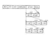
図3は、N個のセクター・アンテナがある場合のハイパーLAN2のMACフレームの構造図である。基本的には図2のMACフレームと構造が類似している。但し、N個のセクターが存在するため、セクター順に第1ブロードキャストチャネルBCH1301から第NブロードキャストチャネルBCHN 302が先に現れ、第1フレームチャネルFCH1 303、第1アクセスフィードバックチャネルACH1304から第NアクセスフィードバックチャネルACHNまでの情報が現れ、第1ダウンリンクチャネルDOWN1310から第NダウンリンクチャネルDOWNN 311、第1アップリンクチャネルUP1 320から第NアップリンクチャネルUPN 321、そして第1ランダムチャネルRCH1 330から第NランダムチャネルRCHN 331が現れる。各々の機能は前記図2において説明したものと同様なので、重ねての説明は省略する。
【0023】
図4は、N個のセクター・アンテナがある場合、各セクターにおける伝送信号列を示す図面である。図3及び図4に示すように、各セクターに対応するチャネルを各アンテナに伝送し、他のセクターがチャネルを使用していれば残りのセクターにはいかなる信号も伝送しない。従って、アクセスポイントAPに含まれる一つのトランスミッタをもってもセクタリングを行うことができるとはいえ、残りのセクターを休止させるために周波数効率が下がる。
【0024】
図5は、従来の多重ホップ転送のためのMACフレームの構造を示す図面である。図5に示すように、多重ホップ転送は、多重ホップMH 502を処理している間、アップリンクUPLINK 501が始まる直前まで、実行される。
【0025】
多重ホップ転送フレームには、中継が可能な端末機または中継器に関する全てのMACフレーム情報をブロードキャストするフォワードブロードキャストチャネル(F−BCH:Forward-Broadcast CHannel)503、中継が可能な端末機または中継器に関する予約データを格納するMACフレーム情報を伝送するフレームチャネル(F−FCH:Forward-Frame CHannel)504、及びMACフレームのアクセス段階で行われたアクセス試行の結果が伝送されるアクセスフィードバックチャネル(F−ACH:Forward-Access feedback CHannel)505の伝送制御チャネルがまず現れる。
【0026】
次に、フォワーディング専用のダウンリンク(F−DL:Forward-Downlink)510及びアップリンク(F−UL:Forward-Downlink)511チャネルが現れ、最後に移動端末が中継できる端末機または中継器に制御情報を伝送するためのフォワードランダムチャネル(F−RCH:Forward-Random CHannel)512が現れる。
【0027】
端末と端末との通信、あるいは端末と中継器との通信にかかる時間と、アクセスポイントAPと端末との送受信にかかる時間とが異なるため、直接伝送される信号と多重ホップ転送信号との干渉を除去することができる。しかし、多重ホップ転送にかかる時間分だけ伝送効率が低下する。
【0028】
【特許文献1】
米国特許第5719868号明細書
【特許文献2】
米国特許第6285857号明細書
【0029】
【発明が解決しようとする課題】
多重ホップデータ転送方法により、一つのアクセスポイントがカバーできる範囲を広げつつ、伝送効率、ひいてはシステム全体の効率を下げず、周波数資源の浪費を低減できる方法が望まれる。
【0030】
そこで、本発明は、多重ホップに関する情報を有する多重ホップデータフレームを処理する多重ホップ転送方法、装置及びその方法に使われる多重ホップフレームを含むMACデータの構造を提供することを目的とする。
【0031】
【課題を解決するための手段】
前記目的を達成するために、本発明では、アクセスポイントと、アクセスポイントと直接通信できる範囲の外に位置している第1移動端末及びアクセスポイントと直接通信できる範囲内に位置している第2移動端末を備えるシステムにおいて、前記アクセスポイントが前記第2移動端末の属しているセクター外にある他の移動端末とデータを送受信する時間中に第1移動端末のデータを前記第2移動端末に伝送する段階と、前記第2移動端末がアクセスポイントとの既存の送受信方法により前記第1移動端末のデータを伝送する段階と、アクセスポイントが前記段階で伝送されるデータを受信する段階と、を含むことを特徴とする多重ホップ転送方法を提供する。前記第2移動端末は、好ましくは、アクセスポイントと通信できる範囲の外に位置している移動端末からのデータをアクセスポイントに伝送する中継器である。また、前記第2端末は、第1移動端末との通信チャネルを設定し、前記アクセスポイントが前記第2移動端末の属しているセクター外にある移動端末とデータを送受信しているか否かを判断し、その判断の結果、前記アクセスポイントが前記第2移動端末の属しているセクター外にある移動端末とデータを送受信している場合、前記第1移動端末のデータを前記第2移動端末が受信するよう構成することが望ましい。
【0032】
前記目的を達成するために、本発明では、アクセスポイントと、アクセスポイントと直接通信できる範囲の外に位置している第1移動端末及びアクセスポイントと直接通信できる範囲内に位置している第2移動端末を備えるシステムにおいて、前記アクセスポイントが既存の送受信方法により前記第1移動端末のデータを第2移動端末に伝送する段階と、前記アクセスポイントが前記第2移動端末の属しているセクター外にある移動端末とデータを送受信する時間中に前記第2移動端末が前記第1移動端末にデータを伝送する段階と、前記第1移動端末が前記段階で伝送されるデータを受信する段階と、を含むことを特徴とする多重ホップ転送方法を提供する。
【0033】
前記目的を達成するために、本発明では、アクセスポイントと通信できる範囲の外に位置している他の第1移動端末との通信チャネルを設定する通信チャネル設定部と、前記アクセスポイントが第2移動端末の属しているセクター外にある移動端末とデータを送受信しているか否かを判断する状態判断部と、前記状態判断部における判断の結果、前記アクセスポイントが前記第2移動端末の属しているセクター外にある移動端末とデータを送受信している場合、前記第1移動端末のデータを前記第2移動端末と送受信する多重ホップデータ伝送部と、を備えることを特徴とする多重ホップ転送が可能な移動端末を提供する。
【0034】
前記目的を達成するために、本発明では、前記多重ホップ転送方法に適用されるMACデータ構造が、現在のMACフレームに対応する制御情報をブロードキャストするブロードキャストチャネル情報値と、システムの資源がどのように現在のMACフレームに割り当てられるかを定義しているフレーム制御チャネル情報を貯蔵しているフレームチャネル情報値と、以前のMACフレームをランダムアクセスする段階で行われたアクセス結果を表わすアクセスフィードバックチャネル情報値と、アクセスポイントから移動端末へと伝送されるダウンデータ値と、アクセスポイントと直接通信できる範囲の外に位置している移動端末からの第1多重ホップデータ値と、移動端末からアクセスポイントへと伝送されるアップデータ値と、アクセスポイントと直接通信できる範囲の外に位置している移動端末からの第2多重ホップデータ値と、ショートトランスポートチャネルが可能でない時に移動端末がアクセスポイントに制御情報を伝送するランダムチャネル値と、を含むことを特徴とする多重ホップ転送方法を提供する。
【0035】
前記第1多重ホップデータ及び第2多重ホップデータは、好ましくは、現在MACフレームに対応する制御情報をブロードキャストするフォワードブロードキャスト制御チャネル情報値と、アクセスポイントからデータを受信して移動端末にデータをフォワーディングするフォワードダウンリンクチャネル情報値と、移動端末からデータを受信してアクセスポイントにデータをフォワーディングするフォワードアップリンクチャネル情報値と、移動端末がアクセスポイントに制御情報を転送するフォワードランダムチャネル情報値と、を含む。また、前記フォワードブロードキャスト制御チャネル情報値は、好ましくは、各セクターに関する全てのMACフレーム情報をブロードキャストするブロードキャストチャネル情報値と、各セクターに関する予約データを表わすMACフレーム情報を転送するフレームチャネル情報値と、MACフレームのアクセス段階で行われたアクセス試行の結果が転送されるアクセスフィードバックチャネル情報値と、を含む。
【0036】
なお、前記多重ホップ転送方法は、コンピュータを手段として実現するためのプログラムとして提供可能であり、該コンピュータプログラムは、コンピュータによって読取可能な記録媒体に格納して、あるいは伝送媒体を通じて提供することができる。同様に、前記本発明によるMACデータ構造は、コンピュータによって読取可能な記録媒体に格納して、あるいは伝送媒体を通じて提供することができる。
【0037】
【発明の実施の形態】
以下、添付した図面に基づき本発明の好適な実施形態について詳細に説明する。図6は、本発明が適用される多重ホップ転送ネットワークの構造図である。図6に示すように、第1移動端末MT1 601がアクセスポイントAP 602と通信をしているとき、第3移動端末MT3 603は、第1中継器SEED1 604や第2移動端末MT2 605に情報を伝送する。同じ時間に、第5移動端末MT5 606もまた、第4移動端末MT4 607または他の第2中継器SEED2 608に情報を伝送できる。第2移動端末MT2 605または第4移動端末MT4 607は、第3移動端末MT3 603または第5移動端末MT5 606から受信した情報をアクセスポイントAP 602に転送する。
【0038】
もし、第3移動端末MT3 603または第5移動端末MT5 606が、第1中継器SEED1 604または第2中継器SEED2 608を用いたとしても、前述同様の過程が行われる。
【0039】
図7Aは、多重ホップ転送ネットワークにおいてアクセスポイントが多重ホップデータを受信する方法を示すフローチャートである。
【0040】
多重ホップ転送ネットワークには、アクセスポイントAPと直接通信できる移動端末MTも存在すれば、その範囲外に位置している移動端末MTも存在する。
【0041】
アクセスポイントAPと直接通信できる範囲の外に位置している移動端末MTは、アクセスポイントAPと通信できる範囲内に位置している移動端末MTまたは中継器SEEDにデータを伝送する。
【0042】
そして、アクセスポイントAPと直接通信できる範囲内に位置している移動端末MTまたは中継器SEEDは、移動端末MT自体または中継器SEEDのデータをアクセスポイントAPに転送する。しかし、常に自分が属しているセクターの移動端末MTとアクセスポイントAPとが通信しているわけではないため、他のセクターにおける移動端末MTとアクセスポイントAPとが通信している時間が生じる。
【0043】
このため、この時間(F−DL時間)中に、移動端末MTまたは中継器SEEDは、アクセスポイントAPと直接通信できる範囲の外に位置している移動端末MTと、多重ホップデータをやり取りする(ステップ710)。そして、多重ホップデータを受信した移動端末MTまたは中継器SEEDは、アクセスポイントAPと通常の方法により多重ホップデータをやり取りする(ステップ711)。
【0044】
そして、アクセスポイントAPは、伝送されたデータを受信して処理する(712)。
【0045】
図7Bは、多重ホップ転送ネットワークにおいてアクセスポイントが多重ホップデータを送信する方法を示すフローチャートである。
【0046】
まず、アクセスポイントAPが、アクセスポイントAPと直接通信できない移動端末MTのデータを、アクセスポイントAPと通信できる移動端末MTに、既存の送受信方法により伝送する(ステップ720)。
【0047】
次に、前記アクセスポイントAPと直接通信できる移動端末MTが属しているセクター外にある移動端末MTとアクセスポイントAPとがデータを送受信する時間(F−UL時間)中に、前記ステップ720で伝送されたデータを、アクセスポイントAPと直接通信できない移動端末MTに伝送する(ステップ721)。
【0048】
これにより、前記アクセスポイントAPと直接通信できない移動端末MTは、前記ステップ721で伝送されたデータ(つまりアクセスポイントAPから伝送されたデータ)を受信する(ステップ722)。
【0049】
図8は、アクセスポイントAPと直接通信できない移動端末MTが、アクセスポイントAPにデータを伝送する方法を示すフローチャートである。
【0050】
まず、アクセスポイントAPと通信できる範囲内に位置している隣接した移動端末MTを選択する(ステップ810)。
【0051】
次に、アクセスポイントAPが前記ステップ810で選択された移動端末MTが属しているセクター外の移動端末MTとデータを送受信しているか否かを判断する(ステップ820)。
【0052】
もし、前記判断の結果、アクセスポイントAPが前記ステップ810で選択された移動端末MTが属しているセクター外の移動端末MTとデータを送受信している場合には、前記選択された移動端末にデータを伝送し(ステップ840)、そうでなければ、通常のデータ伝送を行う(ステップ830)。すなわち、選択された移動端末MT自体がアクセスポイントAPと移動端末MT自体のデータを送受信していたならば、その過程を行う。
【0053】
図9は、アクセスポイントAPと直接通信できない移動端末MTからのデータを他の移動端末MTが中継する方法を示すフローチャートである。
【0054】
アクセスポイントAPと通信できる範囲の外に位置している隣接した移動端末MTとの通信チャネルを設定する(ステップ910)。
【0055】
そして、アクセスポイントAPが前記移動端末MTの属しているセクター外にある他の移動端末とデータを送受信しているか否かを判断する(ステップ920)。これは、前述したように、アクセスポイントAPは他のセクター内の移動端末MTともデータを送受信するため、この時間を用いるためである。
【0056】
前記判断の結果、前記アクセスポイントAPが前記移動端末MTの属しているセクター外にある他の移動端末MTとデータを送受信しているときには、通信チャネルを設定したアクセスポイントAPと通信できる範囲の外に位置している隣接した移動端末のデータを前記移動端末が受信し(ステップ930)、そうでなければ通常のデータ伝送を行う(ステップ940)。すなわち、移動端末MT自体がアクセスポイントAPと移動端末MT自体のデータを送受信していたならば、その過程を行う。
【0057】
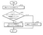
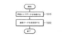
図10は、アクセスポイントAPの多重ホップデータ処理方法を示すフローチャートである。
【0058】
現在アクセスポイントAPがある移動端末MTの属しているセクター外にある他の移動端末MTとデータを送受信している場合には、アクセスポイントAPと通信できる範囲の外に位置している隣接した移動端末のデータを通信できる範囲内に位置している移動端末MTを介して受信し(ステップ1010)、そうでなければ、通信しているセクターの移動端末MTからの通常のデータ送受信を行う(ステップ1020)。
【0059】
図11は、本発明の各セクター別伝送信号列を示す図面である。これは、図4に示した伝送信号列と比べると、基本的構成は類似しているが、アクセスポイントAPと通信しないセクターで多重ホップフレームを割り当てて多重ホップ転送を行う点で違いがある。また、多重ホップフレームが連続的に存在せず、与えられたセクターにアクセスポイントAPとの通信のための資源が割り当てられた場合、普通のダウンリンクまたはアップリンク通信を行った後に再び元の多重ホップフレームに戻る構造を有しているという点で違いがある。
【0060】
ハイパーLAN2に前記方法を適用するために、図5における多重ホップフレーム構造を使用する。多重ホップ伝送フレームには、各セクターに関する全てのMACフレーム情報をブロードキャストするフォワードブロードキャストチャネルF−BCH 503、各セクターに関する予約データを貯蔵しているMACフレーム情報を伝送するフレームチャネルF−FCH 504、及びMACフレームのアクセス段階で行われたアクセス試行の結果が伝送されるアクセスフィードバックチャネルF−ACH 505の伝送制御チャネルが最初に現れる。
【0061】
次に、フォワーディング専用のダウンリンクF−DL 510及びアップリンクF−UL 511チャネルが現れ、最後に移動端末がアクセスポイントに制御情報を伝送するためのフォワードランダムチャネルF−RCH 512が現れる。
【0062】
図12は、アクセスポイントAPと直接通信できない移動端末MTがアクセスポイントAPにデータを伝送するための装置を示す図面である。
【0063】
移動端末選択部1210は、アクセスポイントAPと通信できる範囲内に位置している隣接した移動端末MTを選択する。
【0064】
状態判断部1220は、前記移動端末選択部1210で選択された移動端末MTが属しているセクター外にある移動端末MTとアクセスポイントAPとがデータを送受信しているか否かを判断する。
【0065】
多重ホップデータ伝送部1230は、前記状態判断部1220における判断の結果、前記アクセスポイントAPが前記移動端末の属しているセクター外にある他の移動端末MTとデータを送受信している時間中に、多重ホップデータを送受信する機能を行う。従って、アクセスポイントAPと直接通信できない移動端末MTをアクセスポイントAPと通信可能にする。
【0066】
図13は、アクセスポイントAPと直接通信できない移動端末MTからのデータをアクセスポイントAPに転送するための移動端末MT装置を示す図面である。
【0067】
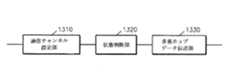
通信チャネル設定部1310は、アクセスポイントAPと通信できる範囲の外に位置している隣接した移動端末MTとの通信チャネルを設定する。
【0068】
状態判断部1320は、他のセクターに位置している移動端末MTと前記アクセスポイントAPとがデータを送受信しているか否かを判断する。
【0069】
多重ホップデータ伝送部1330は、他のセクターに位置している移動端末MTと前記アクセスポイントAPとがデータを送受信している場合、アクセスポイントAPと通信できる範囲の外に位置している隣接した移動端末MTとデータを送受信する。
【0070】
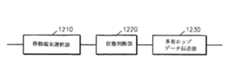
図14は、多重ホップデータを処理するためのアクセスポイントAP装置を示す図面である。
【0071】
多重ホップデータ処理部1410は、現在アクセスポイントAPがある移動端末MTの属しているセクター外にある他の移動端末MTとデータを送受信している場合には、そのアクセスポイントAPと通信できる範囲の外に位置している隣接した移動端末のデータを通信可能な範囲内に位置している移動端末MTを介して受信する、
【0072】
そうでない場合、通常データ送受信部1420は、通信しているセクターの移動端末MTからの通常のデータ送受信を行う。
【0073】
図15ないし図20は、本発明により提案された多重ホップ転送方法を行った場合の性能向上を示すグラフである。実施条件は下記の通りである。まず、チャネルはログディスタンスモデル及びログノーマルフェ−ジングである場合を仮定する。この時、経路損失は下記式1の通りである。
【0074】
【数1】
ここで、dは送信機と受信機とのメートル距離であり、αは経路損失指数である。
【0076】
また、ターゲットアウテージ確率は10%であり、信号対雑音比(SNR)は10-7ビットエラー率(BER)であり、送受信セルは均一な分布を有しており、ユーザ数はポアソン分布を有している。
【0077】
図15は、本発明により提案された多重ホップ転送方法を使用した場合、ユーザ数による性能範囲の向上度を示すグラフである。この時、経路損失指数αは3であると仮定した。
【0078】
図15から見られるように、多重ホップを提供していない場合(centered)、性能範囲は平均ユーザ数と関係なく、多重ホップを提供する場合(forward)に利得を得ることができた。特に、ログノーマルフェ−ジングが存在する場合にログノーマルフェ−ジングに対する発散効果により性能範囲の増加が2倍以上にもなる。
【0079】
図16は、平均ユーザ数を12に固定して経路損失指数を変えたときの性能範囲の変化を示すグラフであり、図17は、平均ユーザ数を12に固定して経路損失指数を変えたときに、多重ホップを使用しない場合と多重ホップを使用する場合とで得られる性能範囲の比率を示すグラフである。
【0080】
図16及び図17から分かるように、ログノーマルフェ−ジングが大きい場合に最大3倍ほどの性能範囲を広げることができた。また、経路損失指数が大きくなる場合より小さい場合に性能範囲の増加度が一層高くなるということが分かる。
【0081】
図18ないし図20は、図15ないし図17と同じ条件であり、端末が多重ホップを支援できず、単に中継器SEEDのみを使用した場合の結果図である。
【0082】
図18は、本発明により提案された多重ホップ転送方法を行うために中継器SEEDのみを使用した場合のユーザ数による性能範囲の向上度を示すグラフである。
【0083】
図面から見られるように、中継器SEEDの数が増えれば性能範囲の増加度が一層高くなるということが分かり、ユーザ数と性能範囲の増加度とは関係ないということがわかる。
【0084】
図19は、中継器SEEDのみを使用した時、平均ユーザ数を12に固定して経路損失指数を変える場合の性能範囲の変化を示すグラフであり、図20は、中継器SEEDのみを使用し、且つ、平均ユーザ数を12に固定して経路損失指数を変える場合、多重ホップを使用しない場合と多重ホップを使用する場合とに得られる性能範囲の比率を示すグラフである。
【0085】
全ての移動端末が多重ホップを支援する場合に比べて性能範囲の改善度が高いとは限らないものの、中継器SEEDの数が約4になれば、全ての移動端末が多重ホップを提供する場合に相当するくらいの性能範囲の改善が見込めるということがわかる。
【0086】
一方、上述した本発明の実施形態はコンピュータにて実行できるプログラムにて作成可能であり、コンピュータにて読取り可能な記録媒体を用いて前記プログラムを動作させる汎用デジタルコンピュータにより具現できる。
【0087】
また、上述した本発明の実施形態で使われたデータの構造はコンピュータにて読取り可能な記録媒体に各種の手段を通じて記録できる。
【0088】
前記コンピュータにて読取り可能な記録媒体は磁気記憶媒体(例えば、ROM、フロッピーディスク、ハードディスクなど)、光学的判読媒体(例えば、CD−ROM、DVD等)及びキャリアウェーブ(例えば、インターネットを介した伝送)などの記憶・伝送媒体を含む。
【0089】
以上、本発明についてその好適な実施形態を中心として説明した。本発明が属する技術分野における当業者であれば、本発明が本発明の本質的な特性から逸脱しない範囲内で変形された形態に具現できるということが理解できる。よって、開示された実施形態は限定的な観点ではなく、説明的な観点から考慮さるべきである。本発明の範囲は前述した説明ではなく特許請求の範囲上に開示されており、それと同等な範囲内にあるあらゆる違いは本発明に含まれたものとして解釈さるべきである。
【0090】
【発明の効果】
上述したように、本発明によれば、複数のセクターのうちアクセスポイントと通信しているセクターはダウンリンク及びアップリンクを通じてアクセスポイントにデータを伝送し、それと同時にアクセスポイントと通信していないセクターは多重ホップに関する情報を有している多重ホップデータフレームを処理することにより、一つのアクセスポイントAPがカバーできる範囲を広げられ、システムを一層経済的に構築でき、周波数資源の浪費を低減できる。
【図面の簡単な説明】
【図1】多重ホップ転送方法の概念図である。
【図2】従来のハイパーLAN2MACフレームの構造図である。
【図3】N個のセクター・アンテナがある場合のハイパーLAN2MACフレームの構造図である。
【図4】N個のセクター・アンテナがある場合の各セクターにおける伝送信号列を示す図面である。
【図5】従来の多重ホップ転送のためのMACフレームの構造図である。
【図6】本発明が適用される多重ホップ転送ネットワークの構造図である。
【図7A】多重ホップ転送ネットワークにおいてアクセスポイントが多重ホップデータを受信する方法を示す図面である。
【図7B】多重ホップ転送ネットワークにおいてアクセスポイントが多重ホップデータを送信する方法を示す図面である。
【図8】アクセスポイントAPと直接通信できない移動端末MTがアクセスポイントAPにデータを伝送するための方法を示す図面である。
【図9】アクセスポイントAPと直接通信できない移動端末MTからのデータを他の移動端末MTが中継する方法を示す図面である。
【図10】アクセスポイントAPの多重ホップデータ処理方法を示す図面である。
【図11】本発明の各セクター別伝送信号列を示す図面である。
【図12】アクセスポイントAPと直接通信できない移動端末MTがアクセスポイントAPにデータを伝送するための装置を示す図面である。
【図13】アクセスポイントAPと直接通信できない移動端末MTからのデータをアクセスポイントAPに転送するための移動端末MT装置を示す図面である。
【図14】多重ホップデータを処理するためのアクセスポイントAP装置を示す図面である。
【図15】本発明の多重ホップ転送方法を使用した場合、ユーザ数による性能範囲の向上度を示す図面である。
【図16】平均ユーザ数を12に固定して経路損失指数を変える場合の性能範囲の変化を示す図面である。
【図17】平均ユーザ数を12に固定して経路損失指数を変える場合、多重ホップを使用しない場合と多重ホップを使用する場合とに得られる性能範囲の比を示す図面である。
【図18】本発明の多重ホップ転送方法を行うために中継器SEEDのみを使用した場合のユーザ数による性能範囲の向上度を示す図面である。
【図19】中継器SEEDのみを使用した時、平均ユーザ数を12に固定して経路損失指数を変える場合の性能範囲の変化を示す図面である。
【図20】中継器SEEDのみを使用し、且つ、平均ユーザ数を12に固定して経路損失指数を変える場合、多重ホップを使用しない場合と多重ホップを使用する場合とに得られる性能範囲の比を示す図面である。
【符号の説明】
BCH1,…,BCHN 第1ブロードキャストチャネル,…,第Nブロードキャストチャネル
FCH1,…,FCHN 第1フレームチャネル,…,第Nフレームチャネル
ACH1,…,ACHN 第1アクセスフィードバックチャネル,…, 第Nアクセスフィードバックチャネル
DOWN1,…,DOWNN 第1ダウンリンクチャネル,…,第Nダウンリンクチャネル
RCH1,…,RCHN 第1ランダムチャネル,…,第Nランダムチャネル
UP1,…,UPN 第1アップリンクチャネル,…,第Nアップリンクチャネル[0001]
[Technical field to which the invention belongs]
The present invention relates to a multi-hop transfer method for processing a multi-hop data frame having information on multi-hop, and a mobile end capable of performing this method.The end of the Related.
[0002]
[Prior art]
In multi-hop transfer, an access point (AP: Access Point) and a mobile terminal (MT: Mobile Terminal) do not directly communicate to transmit information, but one or more mobile terminals MT or pre-installed. It means a method of communication through Oita relay terminal.
[0003]
FIG. 1 is a conceptual diagram of a multi-hop transfer method. In FIG. 1, the first mobile terminal MT1 101 cannot directly communicate with the
[0004]
If there are no other mobile terminals that transfer multiple hops around, or if the channel quality is poor and cannot be transferred, a repeater SEED 104 for multiple hop transfer may be provided.
[0005]
In FIG. 1, if the fourth
[0006]
The conventional method for multi-hop transfer of such a scheme is configured to eliminate interference between the multi-hop transfer signal and the direct transmission signal by assigning a specific time or a specific frequency for the multi-hop transfer. Has been.
[0007]
However, when a new frequency is allocated separately, a transmitter and a receiver that use this allocated frequency are separately required for each mobile terminal MT, and frequency resources are wasted in order to use a new different frequency. There is. In addition, when a specific time is allocated, information transmission cannot be performed directly from another mobile terminal MT to the access point AP during this time, so that the efficiency of the entire system decreases.
[0008]
In recent years, with the spread of local area networks (LANs) and the generalization of their use, there is an interest in wireless LANs that do not require cables to be laid again when relocating office spaces or production facilities in factories. It is growing. A wireless LAN is not a fixed terminal, but a terminal that is constantly moving, such as an automated guided vehicle in a factory or a hand-held computer terminal used in a stock exchange, is connected to a wireless LAN infrastructure and various types of wireless LAN are used. Allows transmission / reception of control information and database search.
[0009]
As an advantage obtained when the wired LAN is made wireless in this way, wiring is not necessary and the terminal can be easily rearranged, and communication is possible even while the terminal is moving. While there is a point that it is possible to construct a LAN, it has a disadvantage that the transmission speed is relatively slow and signal interference may occur compared to a wired LAN.
[0010]
The IEEE (Institute of Electrical and Electronics Engineers) 802 Committee, which establishes a standard proposal for the electrical and electronics field, recognized the need for wireless LAN standardization, and formed the IEEE 802.11 Committee in May 1991 to standardize the work. I started. Thereafter, the provisional standard (DS: Draft standard) 3.0 standard was established in 1996, and the final standard was established in 1997. The third stage is now in the stage after finalization of the IEEE 802.11 final standard, and it is in full swing based on the advantages obtained by establishing standardization, that is, ensuring interoperability, developing related parts, etc. The wireless LAN market is expected to develop actively.
[0011]
Wireless LAN standards can be broadly divided into IEEE 802.11 standards and hyper LAN (Hiper LAN) standards created by the European Telecommunications Standards Institute (ETSI) RES10. IEEE 801.11 is aimed at wireless LANs that provide speeds up to 2 Mbps in the industrial, scientific and medical frequency bands (ISM: Industrial / Scientific / Medical), whereas hyper LANs are intended for users in the 5.2 GHz band. A transmission rate of up to 15 Mbps can be provided.
[0012]
In general, the
[0013]
When the protocol reference model of the
[0014]
Unlike the Carrier Sense Multiple Access / Collision Detection (CSMA / CD) method, which is a non-connectivity structure of IEEE 802.11, the Hyper LAN 2 MAC is a time division multiplex method connectivity structure. Therefore, there is a function of providing quality assurance (QoS: Quality of Service) such as bandwidth, time delay, and bit error rate. Various data such as video, audio, and data can be transmitted simultaneously for such a QoS providing function. Each MAC frame is configured to have the same length of 2 msec and includes six channels.
[0015]
FIG. 2 is a diagram illustrating a MAC frame structure of the
[0016]
The format of the broadcast channel BCH 202 consists of 120 bits and stores broadcast control channel (BCCH) information. The broadcast control channel BCCH is a logical channel that broadcasts control information corresponding to the current MAC frame.
[0017]
When the frame channel FCH 203 is broadcast, frame control channel information (FCCH: Frame Control CHannel) is transmitted. The frame control channel FCCH contains information defining how system resources are allocated to the current MAC frame.
[0018]
An access feedback channel (ACH) 204 is a channel through which an access result obtained at the stage of randomly accessing a previous MAC frame is transmitted.
[0019]
The
[0020]
The
[0021]
Among them, the
[0022]
FIG. 3 is a structural diagram of a MAC frame of the
[0023]
FIG. 4 is a diagram illustrating a transmission signal sequence in each sector when there are N sector antennas. As shown in FIGS. 3 and 4, a channel corresponding to each sector is transmitted to each antenna, and if other sectors use the channel, no signal is transmitted to the remaining sectors. Therefore, although the sectoring can be performed even with one transmitter included in the access point AP, the frequency efficiency is lowered in order to suspend the remaining sectors.
[0024]
FIG. 5 is a diagram illustrating a structure of a conventional MAC frame for multi-hop transfer. As shown in FIG. 5, multi-hop forwarding is performed while processing
[0025]
The multi-hop transfer frame includes a forward-broadcast channel (F-BCH) 503 that broadcasts all MAC frame information related to a relayable terminal or relay, and a relayable terminal or relay. A frame channel (F-FCH) 504 for transmitting MAC frame information for storing reservation data, and an access feedback channel (F-ACH) for transmitting a result of an access attempt performed at the MAC frame access stage : Forward-Access feedback CHannel) 505 transmission control channel appears first.
[0026]
Next, a downlink (F-DL) 510 and an uplink (F-UL) 511 channel dedicated to forwarding appear, and finally control information is transmitted to a terminal or a repeater to which a mobile terminal can relay. Appears as a forward random channel (F-RCH: Forward-Random CHannel) 512.
[0027]
Since the time required for communication between the terminal and the communication between the terminal and the repeater is different from the time required for transmission / reception between the access point AP and the terminal, interference between the directly transmitted signal and the multi-hop transfer signal is reduced. Can be removed. However, the transmission efficiency is reduced by the time required for multi-hop transfer.
[0028]
[Patent Document 1]
US Pat. No. 5,719,868
[Patent Document 2]
US Pat. No. 6,285,857
[0029]
[Problems to be solved by the invention]
There is a need for a method that can reduce the waste of frequency resources without reducing the transmission efficiency and thus the efficiency of the entire system while expanding the range that can be covered by one access point by the multi-hop data transfer method.
[0030]
Accordingly, an object of the present invention is to provide a multi-hop transfer method and apparatus for processing a multi-hop data frame having information on multiple hops, and a structure of MAC data including the multi-hop frame used in the method.
[0031]
[Means for Solving the Problems]
In order to achieve the above object, according to the present invention, the access point and the first mobile terminal located outside the range where direct communication with the access point can be performed and the second mobile terminal located within the range where direct communication with the access point can be performed. In a system including a mobile terminal, the data of the first mobile terminal is transmitted to the second mobile terminal during a time when the access point transmits / receives data to / from another mobile terminal outside the sector to which the second mobile terminal belongs. And the second mobile terminal transmits the data of the first mobile terminal by an existing transmission / reception method with the access point, and the access point receives the data transmitted in the step. A multi-hop transfer method is provided. The second mobile terminal is preferably a relay that transmits data from a mobile terminal located outside the range where communication with the access point is possible to the access point. The second terminal sets a communication channel with the first mobile terminal, and determines whether the access point is transmitting / receiving data to / from a mobile terminal outside the sector to which the second mobile terminal belongs. If the access point is transmitting / receiving data to / from a mobile terminal outside the sector to which the second mobile terminal belongs, the second mobile terminal receives the data of the first mobile terminal. It is desirable to configure so as to.
[0032]
In order to achieve the above object, according to the present invention, the access point and the first mobile terminal located outside the range where direct communication with the access point can be performed and the second mobile terminal located within the range where direct communication with the access point can be performed. In a system including a mobile terminal, the access point transmits data of the first mobile terminal to a second mobile terminal using an existing transmission / reception method, and the access point is outside a sector to which the second mobile terminal belongs. The second mobile terminal transmits data to the first mobile terminal during a time for transmitting / receiving data to / from a certain mobile terminal, and the first mobile terminal receives data transmitted in the step. A multi-hop transfer method is provided.
[0033]
In order to achieve the above object, according to the present invention, a communication channel setting unit for setting a communication channel with another first mobile terminal located outside the range where communication with an access point is possible, and the access point is a second A state determination unit that determines whether or not data is transmitted / received to / from a mobile terminal outside the sector to which the mobile terminal belongs; and, as a result of the determination in the state determination unit, the access point belongs to the second mobile terminal A multi-hop transmission comprising: a multi-hop data transmission unit that transmits / receives data of the first mobile terminal to / from the second mobile terminal when data is transmitted / received to / from a mobile terminal outside a certain sector; Provide a possible mobile terminal.
[0034]
In order to achieve the above object, in the present invention,The MAC data structure applied to the multi-hop transfer method is: Frame channel information storing broadcast channel information values for broadcasting control information corresponding to the current MAC frame and frame control channel information defining how system resources are allocated to the current MAC frame A value, an access feedback channel information value indicating an access result performed at the stage of randomly accessing a previous MAC frame, a downdata value transmitted from the access point to the mobile terminal, and a range in which communication can be performed directly with the access point The first multi-hop data value from the mobile terminal located outside, the updater value transmitted from the mobile terminal to the access point, and the mobile terminal located outside the range where direct communication with the access point is possible Second multi-hop data value and show Characterized in that it comprises a random channel value the mobile terminal transmits the control information to the access point when not possible transport channelMulti-hop transfer method I will provide a.
[0035]
The first multi-hop data and the second multi-hop data are preferably forward broadcast control channel information values for broadcasting control information corresponding to the current MAC frame, and data is received from the access point and forwarded to the mobile terminal. Forward downlink channel information value, forward uplink channel information value for receiving data from the mobile terminal and forwarding the data to the access point, forward random channel information value for the mobile terminal to transfer control information to the access point, including. The forward broadcast control channel information value is preferably a broadcast channel information value for broadcasting all MAC frame information for each sector, a frame channel information value for transferring MAC frame information representing reservation data for each sector, and And an access feedback channel information value to which a result of an access attempt performed in the access step of the MAC frame is transferred.
[0036]
The multi-hop transfer method can be provided as a program for realizing a computer as means, and the computer program can be stored in a computer-readable recording medium or provided through a transmission medium. . Similarly, the MAC data structure according to the present invention may be stored in a computer-readable recording medium or provided through a transmission medium.
[0037]
DETAILED DESCRIPTION OF THE INVENTION
Hereinafter, preferred embodiments of the present invention will be described in detail with reference to the accompanying drawings. FIG. 6 is a structural diagram of a multi-hop transfer network to which the present invention is applied. As shown in FIG. 6, when the first
[0038]
If the third
[0039]
FIG. 7A is a flowchart illustrating a method for an access point to receive multi-hop data in a multi-hop transport network.
[0040]
In the multi-hop transfer network, there are mobile terminals MT that can directly communicate with the access point AP, and there are mobile terminals MT located outside the range.
[0041]
The mobile terminal MT located outside the range that can directly communicate with the access point AP transmits data to the mobile terminal MT or the repeater SEED located within the range that can communicate with the access point AP.
[0042]
Then, the mobile terminal MT or repeater SEED located within a range where it can communicate directly with the access point AP transfers the data of the mobile terminal MT itself or the repeater SEED to the access point AP. However, since the mobile terminal MT in the sector to which the mobile terminal MT belongs does not always communicate with the access point AP, a time for communication between the mobile terminal MT and the access point AP in another sector occurs.
[0043]
For this reason, during this time (F-DL time), the mobile terminal MT or the relay SEED exchanges multi-hop data with the mobile terminal MT located outside the range where it can directly communicate with the access point AP ( Step 710). The mobile terminal MT or the relay SEED that has received the multi-hop data exchanges the multi-hop data with the access point AP by a normal method (step 711).
[0044]
Then, the access point AP receives and processes the transmitted data (712).
[0045]
FIG. 7B is a flowchart illustrating a method for an access point to transmit multi-hop data in a multi-hop transport network.
[0046]
First, the access point AP transmits data of the mobile terminal MT that cannot directly communicate with the access point AP to the mobile terminal MT that can communicate with the access point AP by an existing transmission / reception method (step 720).
[0047]
Next, transmission is performed in
[0048]
As a result, the mobile terminal MT that cannot directly communicate with the access point AP receives the data transmitted in the step 721 (that is, data transmitted from the access point AP) (step 722).
[0049]
FIG. 8 is a flowchart showing a method for transmitting data to the access point AP by the mobile terminal MT that cannot directly communicate with the access point AP.
[0050]
First, an adjacent mobile terminal MT located within a range where communication with the access point AP can be performed is selected (step 810).
[0051]
Next, it is determined whether or not the access point AP is transmitting / receiving data to / from a mobile terminal MT outside the sector to which the mobile terminal MT selected in
[0052]
If it is determined that the access point AP is transmitting / receiving data to / from a mobile terminal MT outside the sector to which the mobile terminal MT selected in
[0053]
FIG. 9 is a flowchart illustrating a method in which another mobile terminal MT relays data from the mobile terminal MT that cannot directly communicate with the access point AP.
[0054]
A communication channel with an adjacent mobile terminal MT located outside the range where communication with the access point AP can be performed is set (step 910).
[0055]
Then, it is determined whether the access point AP is transmitting / receiving data to / from another mobile terminal outside the sector to which the mobile terminal MT belongs (step 920). As described above, this is because the access point AP uses this time because it transmits and receives data to and from the mobile terminals MT in other sectors.
[0056]
As a result of the determination, when the access point AP is transmitting / receiving data to / from another mobile terminal MT outside the sector to which the mobile terminal MT belongs, the access point AP is out of the range that can communicate with the access point AP that has set a communication channel. The mobile terminal receives the data of the adjacent mobile terminal located at (step 930), otherwise performs normal data transmission (step 940). That is, if the mobile terminal MT itself transmits and receives data between the access point AP and the mobile terminal MT itself, the process is performed.
[0057]
FIG. 10 is a flowchart showing a multi-hop data processing method of the access point AP.
[0058]
When data is being transmitted / received to / from another mobile terminal MT outside the sector to which the mobile terminal MT to which the access point AP currently belongs is located, the adjacent mobile located outside the range that can communicate with the access point AP The terminal data is received via the mobile terminal MT located within a communicable range (step 1010). Otherwise, normal data transmission / reception is performed from the mobile terminal MT of the communicating sector (step 1010). 1020).
[0059]
FIG. 11 shows a transmission signal sequence for each sector according to the present invention. This is similar in basic structure to the transmission signal sequence shown in FIG. 4, but differs in that multiple hop frames are assigned to a sector that does not communicate with the access point AP and multiple hop transfer is performed. In addition, when multiple hop frames are not continuously present and resources for communication with the access point AP are allocated to a given sector, the original multiplex frame is again transmitted after performing normal downlink or uplink communication. There is a difference in that it has a structure returning to a hop frame.
[0060]
In order to apply the method to the
[0061]
Next, a downlink F-
[0062]
FIG. 12 is a diagram illustrating an apparatus for transmitting data to an access point AP by a mobile terminal MT that cannot directly communicate with the access point AP.
[0063]
The mobile
[0064]
The
[0065]
As a result of the determination in the
[0066]
FIG. 13 is a diagram showing a mobile terminal MT apparatus for transferring data from the mobile terminal MT that cannot directly communicate with the access point AP to the access point AP.
[0067]
The communication
[0068]
The
[0069]
The multi-hop
[0070]
FIG. 14 is a diagram illustrating an access point AP apparatus for processing multi-hop data.
[0071]
The multi-hop
[0072]
Otherwise, the normal data transmission /
[0073]
15 to 20 are graphs showing performance improvement when the multi-hop transfer method proposed by the present invention is performed. The implementation conditions are as follows. First, it is assumed that the channel is a log distance model and log normal fading. At this time, the path loss is as shown in
[0074]
[Expression 1]
Here, d is a meter distance between the transmitter and the receiver, and α is a path loss index.
[0076]
The target outage probability is 10%, and the signal-to-noise ratio (SNR) is 10-7 It is a bit error rate (BER), the transmission and reception cells have a uniform distribution, and the number of users has a Poisson distribution.
[0077]
FIG. 15 is a graph showing the improvement of the performance range according to the number of users when the multi-hop transfer method proposed by the present invention is used. At this time, the path loss index α was assumed to be 3.
[0078]
As can be seen from FIG. 15, when multiple hops are not provided (centered), the performance range can be gained when multiple hops are provided (forward) regardless of the average number of users. In particular, when log normal fading exists, the performance range increases more than twice due to the divergence effect on log normal fading.
[0079]
FIG. 16 is a graph showing a change in performance range when the average number of users is fixed at 12 and the path loss index is changed. FIG. 17 is a graph showing the change in the path loss index when the average number of users is fixed at 12. It is a graph which shows the ratio of the performance range obtained when not using multiple hops and using multiple hops.
[0080]
As can be seen from FIGS. 16 and 17, when the log normal fading is large, the performance range can be expanded up to three times. It can also be seen that the degree of increase in the performance range is further increased when the path loss index is smaller than when the path loss index is increased.
[0081]
FIG. 18 to FIG. 20 are the same conditions as FIG. 15 to FIG. 17, and are results when the terminal cannot support multiple hops and uses only the repeater SEED.
[0082]
FIG. 18 is a graph showing the improvement of the performance range according to the number of users when only the repeater SEED is used to perform the multi-hop transfer method proposed by the present invention.
[0083]
As can be seen from the drawing, it can be seen that as the number of repeaters SEED increases, the degree of increase in the performance range becomes higher, and the number of users and the degree of increase in the performance range are not related.
[0084]
FIG. 19 is a graph showing a change in the performance range when the average number of users is fixed at 12 and the path loss index is changed when only the repeater SEED is used, and FIG. 20 uses only the repeater SEED. When the average number of users is fixed to 12 and the path loss index is changed, it is a graph showing the ratio of the performance range obtained when not using multiple hops and when using multiple hops.
[0085]
Although the improvement in the performance range is not always higher than when all mobile terminals support multiple hops, all mobile terminals provide multiple hops if the number of repeaters SEED is about 4. It can be seen that an improvement in the performance range corresponding to is expected.
[0086]
On the other hand, the above-described embodiment of the present invention can be created by a program that can be executed by a computer, and can be realized by a general-purpose digital computer that operates the program using a computer-readable recording medium.
[0087]
In addition, the data structure used in the above-described embodiment of the present invention can be recorded on a computer-readable recording medium through various means.
[0088]
The computer-readable recording medium is a magnetic storage medium (for example, ROM, floppy disk, hard disk, etc.), an optical interpretation medium (for example, CD-ROM, DVD, etc.) and carrier wave (for example, transmission via the Internet). ) And other storage / transmission media.
[0089]
In the above, this invention was demonstrated centering on the preferable embodiment. Those skilled in the art to which the present invention pertains can understand that the present invention can be embodied in a modified form without departing from the essential characteristics of the present invention. Thus, the disclosed embodiments are to be considered from an illustrative rather than a limiting perspective. The scope of the present invention is disclosed not in the foregoing description but in the claims, and any difference that falls within the equivalent scope should be construed as being included in the present invention.
[0090]
【The invention's effect】
As described above, according to the present invention, a sector communicating with an access point among a plurality of sectors transmits data to the access point through the downlink and uplink, and at the same time, a sector not communicating with the access point By processing a multi-hop data frame having information on multiple hops, the range that one access point AP can cover can be expanded, the system can be constructed more economically, and waste of frequency resources can be reduced.
[Brief description of the drawings]
FIG. 1 is a conceptual diagram of a multi-hop transfer method.
FIG. 2 is a structural diagram of a conventional
FIG. 3 is a structural diagram of a
FIG. 4 is a diagram illustrating a transmission signal sequence in each sector when there are N sector antennas.
FIG. 5 is a structural diagram of a MAC frame for conventional multi-hop transfer.
FIG. 6 is a structural diagram of a multi-hop transfer network to which the present invention is applied.
FIG. 7A illustrates a method for an access point to receive multi-hop data in a multi-hop transport network.
FIG. 7B illustrates a method for an access point to transmit multi-hop data in a multi-hop transport network.
FIG. 8 is a diagram illustrating a method for a mobile terminal MT that cannot directly communicate with an access point AP to transmit data to the access point AP.
FIG. 9 is a diagram illustrating a method in which another mobile terminal MT relays data from a mobile terminal MT that cannot directly communicate with an access point AP.
FIG. 10 is a diagram illustrating a multi-hop data processing method of an access point AP.
FIG. 11 is a diagram illustrating a transmission signal sequence for each sector according to the present invention.
FIG. 12 shows an apparatus for transmitting data to an access point AP by a mobile terminal MT that cannot directly communicate with the access point AP.
FIG. 13 is a diagram showing a mobile terminal MT device for transferring data from a mobile terminal MT that cannot directly communicate with the access point AP to the access point AP.
FIG. 14 shows an access point AP apparatus for processing multi-hop data.
FIG. 15 is a diagram illustrating the improvement in the performance range depending on the number of users when the multi-hop transfer method of the present invention is used.
FIG. 16 is a diagram showing changes in the performance range when the average number of users is fixed at 12 and the path loss index is changed.
FIG. 17 is a diagram showing a ratio of performance ranges obtained when a multipath is not used and when a multihop is used when the path loss index is changed while fixing the average number of users to 12;
FIG. 18 is a diagram illustrating the improvement of the performance range according to the number of users when only the repeater SEED is used to perform the multi-hop transfer method of the present invention.
FIG. 19 is a diagram showing a change in performance range when the average number of users is fixed at 12 and the path loss index is changed when only the repeater SEED is used.
FIG. 20 shows the range of performance obtained when only the repeater SEED is used and the path loss index is changed by fixing the average number of users to 12 and when multiple hops are not used and when multiple hops are used. It is drawing which shows ratio.
[Explanation of symbols]
BCH1 , ..., BCHN 1st broadcast channel, ..., Nth broadcast channel
FCH1 , ..., FCHN 1st frame channel, ..., Nth frame channel
ACH1 , ..., ACHN 1st access feedback channel, ..., Nth access feedback channel
DOWN1 , ..., DOWNN 1st downlink channel, ..., Nth downlink channel
RCH1 , ..., RCHN 1st random channel, ..., Nth random channel
UP1 , ..., UPN 1st uplink channel, ..., Nth uplink channel
Claims (9)
Translated fromJapanese(a)前記アクセスポイントが前記第2移動端末の属しているセクター外にある他の移動端末とデータを送受信する時間中に第1移動端末のデータを前記第2移動端末に送信する段階と、
(b)前記第2移動端末がアクセスポイントとの既存の送受信方法により前記第1移動端末のデータを送信する段階と、
(c)アクセスポイントが前記(b)段階で送信されたデータを受信する段階と、を含むことを特徴とする多重ホップ転送方法。In a system comprising an access point, a first mobile terminal located outside a range that can directly communicate with the access point, and a second mobile terminal located within a range that can communicate directly with the access point,
(A) transmitting the data of the first mobile terminal to the second mobile terminal during a time when the access point transmits / receives data to / from another mobile terminal outside the sector to which the second mobile terminal belongs;
(B) the second mobile terminal transmitting data of the first mobile terminal by an existing transmission / reception method with an access point;
(C) The access point includes the step of receiving the data transmitted in the step (b).
アクセスポイントと通信できる範囲の外に位置している移動端末からのデータをアクセスポイントに送信する中継器であることを特徴とする請求項1に記載の多重ホップ転送方法。The second mobile terminal is
The multi-hop transfer method according to claim 1, wherein the multi-hop transfer method is a repeater that transmits data from a mobile terminal located outside a range in which communication with the access point is possible to the access point.
(a)第1移動端末との通信チャネルを設定する段階と、
(b)前記アクセスポイントが前記第2移動端末の属しているセクター外にある移動端末とデータを送受信しているか否かを判断する段階と、
(c)前記(b)段階における判断の結果、前記アクセスポイントが前記第2移動端末の属しているセクター外にある移動端末とデータを送受信している場合、前記第1移動端末のデータを前記第2移動端末が受信する段階と、を含むことを特徴とする請求項1に記載の多重ホップ転送方法。The second mobile terminal is
(A) setting a communication channel with the first mobile terminal;
(B) determining whether the access point is transmitting / receiving data to / from a mobile terminal outside the sector to which the second mobile terminal belongs;
(C) As a result of the determination in the step (b), when the access point transmits / receives data to / from a mobile terminal outside the sector to which the second mobile terminal belongs, the data of the first mobile terminal is The multi-hop transfer method according to claim 1, further comprising a step of receiving by the second mobile terminal.
(a)前記アクセスポイントが既存の送受信方法により前記第1移動端末のデータを第2移動端末に送信する段階と、
(b)前記アクセスポイントが前記第2移動端末の属しているセクター外にある移動端末とデータを送受信する時間中に前記第2移動端末が前記第1移動端末にデータを送信する段階と、
(c)前記第1移動端末が前記(b)段階で送信されたデータを受信する段階と、を含むことを特徴とする多重ホップ転送方法。In a system comprising an access point, a first mobile terminal located outside a range that can directly communicate with the access point, and a second mobile terminal located within a range that can communicate directly with the access point,
(A) the access point transmits data of the first mobile terminal to a second mobile terminal by an existing transmission / reception method;
(B) the second mobile terminal transmits data to the first mobile terminal during a time when the access point transmits / receives data to / from a mobile terminal outside the sector to which the second mobile terminal belongs;
(C) The first mobile terminal includes the step of receiving the data transmitted in the step (b).
前記アクセスポイントが第2移動端末の属しているセクター外にある移動端末とデータを送受信しているか否かを判断する状態判断部と、
前記状態判断部における判断の結果、前記アクセスポイントが前記第2移動端末の属しているセクター外にある移動端末とデータを送受信している場合、前記第1移動端末のデータを前記第2移動端末と送受信する多重ホップデータ送信部と、を備えることを特徴とする多重ホップ転送が可能な移動端末。A communication channel setting unit for setting a communication channel with another first mobile terminal located outside the range capable of communicating with the access point;
A state determination unit for determining whether the access point is transmitting / receiving data to / from a mobile terminal outside the sector to which the second mobile terminal belongs;
If the access point transmits / receives data to / from a mobile terminal outside the sector to which the second mobile terminal belongs as a result of the determination in the state determination unit, the data of the first mobile terminal is transferred to the second mobile terminal And a multi-hop data transmitter for transmitting and receiving the mobile terminal.
現在のMACフレームに対する制御情報をブロードキャストするブロードキャストチャネル情報値と、
システム資源がどのように現在のMACフレームに割り当てられるかを定義しているフレーム制御チャネル情報を貯蔵しているフレームチャネル情報値と、
以前のMACフレームをランダムアクセスする段階で行なわれたアクセス結果を貯蔵しているアクセスフィードバックチャネル情報値と、
アクセスポイントから移動端末へと送信されるダウンデータ値と、
アクセスポイントと直接通信できる範囲の外に位置している移動端末からの第1多重ホップデータ値と、
移動端末からアクセスポイントへと送信されるアップデータ値と、
アクセスポイントと直接通信できる範囲の外に位置している移動端末からの第2多重ホップデータ値と、
ショートトランスポートチャネルが可能でない時に移動端末がアクセスポイントに制御情報を送信するランダムチャネル値と、
を含むことを特徴とする請求項1ないし請求項4のいずれか1項に記載の多重ホップ転送方法。The MAC data structure applied to the multi-hop transfer method is:
A broadcast channel information value for broadcasting control information for the current MAC frame;
A frame channel information value storing frame control channel information defining how system resources are allocated to the current MAC frame; and
An access feedback channel information value storing an access result made in the stage of randomly accessing a previous MAC frame;
A downdata value transmitted from the access point to the mobile terminal;
A first multi-hop data value from a mobile terminal located outside the range that can communicate directly with the access point;
An updater value transmitted from the mobile terminal to the access point;
A second multi-hop data value from a mobile terminal located outside the range that can communicate directly with the access point;
A random channel value for the mobile terminal to send control information to the access point when a short transport channel is not possible; and
5. The multi-hop transfer method according toclaim 1 , comprising:
現在MACフレームに対応する制御情報をブロードキャストするフォワードブロードキャスト制御チャネル情報値と、
アクセスポイントからデータを受信して移動端末にデータをフォワーディングするフォワードダウンリンクチャネル情報値と、
移動端末からデータを受信してアクセスポイントにデータをフォワーディングするフォワードアップリンクチャネル情報値と、
移動端末がアクセスポイントに制御情報を転送するフォワードランダムチャネル情報値と、
を含むことを特徴とする請求項7に記載の多重ホップ転送方法。The first multi-hop data andthe second multi-hop data,
A forward broadcast control channel information value for broadcasting control information corresponding to the current MAC frame;
A forward downlink channel information value for receiving data from the access point and forwarding the data to the mobile terminal;
A forward uplink channel information value for receiving data from the mobile terminal and forwarding the data to the access point;
A forward random channel information value in which the mobile terminal transfers control information to the access point; and
Themulti-hop transfer method according to claim 7, further comprising:
各セクターに関する全てのMACフレーム情報をブロードキャストするブロードキャストチャネル情報値と、
各セクターに関する予約データを表わすMACフレーム情報を転送するフレームチャネル情報値と、
MACフレームのアクセス段階で行なわれたアクセス試行の結果が転送されるアクセスフィードバックチャネル情報値と、
を含むことを特徴とする請求項8に記載の多重ホップ転送方法。The forward broadcast control channel information value is:
A broadcast channel information value that broadcasts all MAC frame information for each sector;
A frame channel information value for transferring MAC frame information representing reservation data for each sector;
An access feedback channel information value to which a result of an access attempt made in the access step of the MAC frame is transferred;
Themulti-hop transfer method according to claim 8, comprising:
Applications Claiming Priority (1)
| Application Number | Priority Date | Filing Date | Title |
|---|---|---|---|
| KR1020020019722AKR100856045B1 (en) | 2002-04-11 | 2002-04-11 | Multi-hop forwarding method, apparatus, and media access control data data structure used in the method |
Publications (2)
| Publication Number | Publication Date |
|---|---|
| JP2004007440A JP2004007440A (en) | 2004-01-08 |
| JP3792662B2true JP3792662B2 (en) | 2006-07-05 |
Family
ID=28450140
Family Applications (1)
| Application Number | Title | Priority Date | Filing Date |
|---|---|---|---|
| JP2003052184AExpired - Fee RelatedJP3792662B2 (en) | 2002-04-11 | 2003-02-28 | Multi-hop transfer method and mobile terminal capable of multi-hop transfer |
Country Status (5)
| Country | Link |
|---|---|
| US (1) | US20050259676A1 (en) |
| EP (1) | EP1353482A3 (en) |
| JP (1) | JP3792662B2 (en) |
| KR (1) | KR100856045B1 (en) |
| CN (1) | CN1233107C (en) |
Families Citing this family (30)
| Publication number | Priority date | Publication date | Assignee | Title |
|---|---|---|---|---|
| JP3712996B2 (en)* | 2002-07-19 | 2005-11-02 | 松下電器産業株式会社 | Communication terminal apparatus and handover method |
| US7646752B1 (en)* | 2003-12-31 | 2010-01-12 | Nortel Networks Limited | Multi-hop wireless backhaul network and method |
| DE102004019106B4 (en)* | 2004-04-20 | 2009-03-12 | Nokia Siemens Networks Gmbh & Co.Kg | Method for multiple use of a cellular radio interface |
| SE0401574D0 (en)* | 2004-06-18 | 2004-06-18 | Henrik Ehrnlund | Wireless sensor network |
| KR100899751B1 (en)* | 2005-03-09 | 2009-05-27 | 삼성전자주식회사 | Signal relay system and method in communication system |
| US7486928B2 (en) | 2005-04-14 | 2009-02-03 | Kddi Corporation | Methods and apparatus for wireless communications |
| KR100644690B1 (en)* | 2005-04-15 | 2006-11-10 | 삼성전자주식회사 | Method and apparatus for efficient frame transmission in wireless mesh network |
| US7548517B2 (en)* | 2005-04-25 | 2009-06-16 | Motorola, Inc. | Method and apparatus for determining the location of a node in a wireless system |
| US8040826B2 (en)* | 2006-03-03 | 2011-10-18 | Samsung Electronics Co., Ltd | Apparatus and method for supporting relay service in a multi-hop relay broadband wireless access communication system |
| KR100781521B1 (en)* | 2006-05-03 | 2007-12-03 | 삼성전자주식회사 | Method and apparatus for detecting change of device under wireless network environment |
| EP1855492B1 (en)* | 2006-05-12 | 2008-06-04 | NTT DoCoMo, Inc. | Method, apparatus and system for reusing resources in a telecommunication network using repeaters. |
| WO2008002436A2 (en)* | 2006-06-23 | 2008-01-03 | Bae Systems Information And Electronic Systems Integration Inc. | Supporting mobile ad-hoc network (manet) and point to multi-point (pmp) communications among nodes in a wireless network |
| EP2055022A1 (en)* | 2006-07-27 | 2009-05-06 | Telefonaktiebolaget LM Ericsson (PUBL) | Hierarchical broadcast transmission via multiple transmitters |
| KR100983942B1 (en)* | 2006-08-18 | 2010-09-27 | 후지쯔 가부시끼가이샤 | Communication method for use in multi-hop wireless communication system, multi-hop wireless communication system, base station apparatus, intermediate apparatus, and use equipment |
| US20080075017A1 (en)* | 2006-09-21 | 2008-03-27 | Stephen Patrick Kramer | System and Method for Analyzing Dynamics of Communications in a Network |
| CN101166055B (en)* | 2006-10-18 | 2011-06-01 | 华为技术有限公司 | Multi-hop relay method and multi-hop relay system |
| US20080181176A1 (en)* | 2006-10-30 | 2008-07-31 | Hyunjeong Lee | Framework to design new mac message exchange procedure related to mobile station (ms) handover in multi-hop relay broadband wireless access network |
| US8681743B2 (en) | 2006-12-08 | 2014-03-25 | Samsung Electronics Co., Ltd. | Apparatus and method for selecting frame structure in multihop relay broadband wireless access communication system |
| KR100985396B1 (en)* | 2006-12-08 | 2010-10-05 | 삼성전자주식회사 | Apparatus and method for selecting frame structure in broadband wireless access communication system using multi-hop relay method |
| US8224272B1 (en)* | 2006-12-15 | 2012-07-17 | Marvell International Ltd. | System for signal metric based receive selection |
| US20080165881A1 (en)* | 2007-01-08 | 2008-07-10 | Zhifeng Tao | Method for Accessing Channels in OFDMA Mobile Multihop Relay Networks |
| KR100949986B1 (en) | 2007-02-26 | 2010-03-30 | 삼성전자주식회사 | Apparatus and method for transmitting and receiving control information in broadband wireless communication system using multi-hop relay method |
| KR101434317B1 (en)* | 2008-02-01 | 2014-08-27 | 삼성전자주식회사 | Service repeater relaying service, service receiving apparatus relaying the service, and methods thereof |
| US8335466B2 (en)* | 2008-12-19 | 2012-12-18 | Research In Motion Limited | System and method for resource allocation |
| CN102271016B (en)* | 2010-06-07 | 2015-09-23 | 上海无线通信研究中心 | A kind of collocation method of novel TDD HARQ UL Un subframe |
| WO2012059049A1 (en)* | 2010-11-02 | 2012-05-10 | 中国移动通信集团公司 | Method, device and system for data transmission |
| CN102469509A (en)* | 2010-11-02 | 2012-05-23 | 中国移动通信集团公司 | Data transmission method, device and system |
| CN103209468B (en) | 2012-01-17 | 2016-05-18 | 华为终端有限公司 | Method, access point and the website of wireless transmission |
| US9585078B2 (en)* | 2013-01-20 | 2017-02-28 | Apple Inc. | Offloading traffic via a wireless peer-to-peer connection |
| CN108112013B (en)* | 2013-03-13 | 2020-12-15 | 华为技术有限公司 | Data transmission method, device and system |
Family Cites Families (9)
| Publication number | Priority date | Publication date | Assignee | Title |
|---|---|---|---|---|
| US5268933A (en)* | 1991-09-27 | 1993-12-07 | Motorola, Inc. | Data packet alignment in a communication system |
| US5719868A (en)* | 1995-10-05 | 1998-02-17 | Rockwell International | Dynamic distributed, multi-channel time division multiple access slot assignment method for a network of nodes |
| US5924033A (en)* | 1996-05-03 | 1999-07-13 | Telefonaktiebolaget L/M Ericsson (Publ) | Communication control circuitry and method for a group of commonly-moving mobile transceiver units |
| US5937357A (en)* | 1996-05-15 | 1999-08-10 | Nec Corporation | Network comprising base stations for selectivity calling mobile units by call radio signals of different bit rates in phase coincidence |
| US6067297A (en)* | 1996-06-28 | 2000-05-23 | Symbol Technologies, Inc. | Embedded access point supporting communication with mobile unit operating in power-saving mode |
| BR9808149A (en)* | 1997-03-03 | 2000-03-28 | Salbu Res & Dev Pty Ltd | Process of transmitting data between stations in a cellular wireless communication system and its cellular wireless communication system |
| US6285857B1 (en)* | 1997-05-01 | 2001-09-04 | At&T Corp. | Multi-hop telecommunications system and method |
| DE19950005A1 (en)* | 1999-10-18 | 2001-04-19 | Bernhard Walke | Range enhancement operating method for mobile radio communications base station uses mobile stations within normal range as relay stations for reaching mobile stations outside normal operating range |
| US6804521B2 (en)* | 2000-01-18 | 2004-10-12 | Nortel Networks Limited | Multi-beam antenna system for high speed data |
- 2002
- 2002-04-11KRKR1020020019722Apatent/KR100856045B1/ennot_activeExpired - Fee Related
- 2003
- 2003-02-13EPEP03250883Apatent/EP1353482A3/ennot_activeWithdrawn
- 2003-02-13CNCNB031038522Apatent/CN1233107C/ennot_activeExpired - Fee Related
- 2003-02-28JPJP2003052184Apatent/JP3792662B2/ennot_activeExpired - Fee Related
- 2003-04-01USUS10/402,945patent/US20050259676A1/ennot_activeAbandoned
Also Published As
| Publication number | Publication date |
|---|---|
| EP1353482A3 (en) | 2003-12-17 |
| CN1450728A (en) | 2003-10-22 |
| US20050259676A1 (en) | 2005-11-24 |
| EP1353482A2 (en) | 2003-10-15 |
| KR100856045B1 (en) | 2008-09-02 |
| JP2004007440A (en) | 2004-01-08 |
| CN1233107C (en) | 2005-12-21 |
| KR20030080874A (en) | 2003-10-17 |
Similar Documents
| Publication | Publication Date | Title |
|---|---|---|
| JP3792662B2 (en) | Multi-hop transfer method and mobile terminal capable of multi-hop transfer | |
| KR100922078B1 (en) | Link Capacity Increase with Simultaneous Transmissions in Centralized Wireless Local Area Networks | |
| EP2157808B1 (en) | Adaptive management method for wireless transfer network containing base station and wireless relay stations | |
| US8255714B2 (en) | System and method for establishing a direct link on the high throughput channel of a multi-rate channel wireless communications network | |
| CA2339636C (en) | Mobile terminal initiated and assisted antenna selection | |
| US7920825B2 (en) | Method and apparatus for transmitting and receiving data using multi-user superposition coding in a wireless relay system | |
| US20090232049A1 (en) | System and method for a multiple hop wireless network | |
| JP4976858B2 (en) | Resource allocation method and apparatus in relay-based cellular configuration | |
| EP2157806A1 (en) | Method for joining a wireless communication device to a wireless transmission network | |
| JP2008295014A (en) | System and method for channel selection management in a wireless communication network | |
| EP1448011B1 (en) | A method of selecting a path to establish a telecommunication link | |
| JP5683723B2 (en) | Method for improving topology mapping in a wireless communication network | |
| WO2017084485A1 (en) | System broadcast message transmission method and apparatus | |
| JP2010056652A (en) | Radio communication system, base station, and scheduling method | |
| CN112637789B (en) | VHF and UHF section fusion intelligent ad hoc network method | |
| Irnich et al. | Capacity of a relaying infrastructure for broadband radio coverage of urban areas | |
| US9510381B2 (en) | Scheduling method and apparatus in system performing device-to-device communication | |
| US20240089761A1 (en) | Advertisement of wireless connection quality estimation | |
| CN106131887B (en) | Distributed topology control method based on serial interference cancellation | |
| Chen et al. | An opportunistic multiradio MAC protocol in multirate wireless ad hoc networks | |
| Lee et al. | A fully-distributed control time slot assignment protocol for large wireless mesh networks | |
| JP2005341344A (en) | Wireless communication method, wireless communication apparatus, and wireless communication system | |
| Kumar et al. | An Improved Network Topology Acquisition process in IEEE 802.16 j non-transparent mode relay networks | |
| Toham et al. | Multi-interfaces and multi-channels multi-hop ad hoc networks: Overview and challenges | |
| JP6082995B2 (en) | Communication method and communication system |
Legal Events
| Date | Code | Title | Description |
|---|---|---|---|
| A977 | Report on retrieval | Free format text:JAPANESE INTERMEDIATE CODE: A971007 Effective date:20050815 | |
| A131 | Notification of reasons for refusal | Free format text:JAPANESE INTERMEDIATE CODE: A131 Effective date:20050817 | |
| A521 | Written amendment | Free format text:JAPANESE INTERMEDIATE CODE: A523 Effective date:20051117 | |
| TRDD | Decision of grant or rejection written | ||
| A01 | Written decision to grant a patent or to grant a registration (utility model) | Free format text:JAPANESE INTERMEDIATE CODE: A01 Effective date:20060315 | |
| A61 | First payment of annual fees (during grant procedure) | Free format text:JAPANESE INTERMEDIATE CODE: A61 Effective date:20060405 | |
| R150 | Certificate of patent or registration of utility model | Free format text:JAPANESE INTERMEDIATE CODE: R150 | |
| FPAY | Renewal fee payment (event date is renewal date of database) | Free format text:PAYMENT UNTIL: 20090414 Year of fee payment:3 | |
| FPAY | Renewal fee payment (event date is renewal date of database) | Free format text:PAYMENT UNTIL: 20100414 Year of fee payment:4 | |
| FPAY | Renewal fee payment (event date is renewal date of database) | Free format text:PAYMENT UNTIL: 20110414 Year of fee payment:5 | |
| FPAY | Renewal fee payment (event date is renewal date of database) | Free format text:PAYMENT UNTIL: 20120414 Year of fee payment:6 | |
| FPAY | Renewal fee payment (event date is renewal date of database) | Free format text:PAYMENT UNTIL: 20130414 Year of fee payment:7 | |
| FPAY | Renewal fee payment (event date is renewal date of database) | Free format text:PAYMENT UNTIL: 20130414 Year of fee payment:7 | |
| FPAY | Renewal fee payment (event date is renewal date of database) | Free format text:PAYMENT UNTIL: 20140414 Year of fee payment:8 | |
| R250 | Receipt of annual fees | Free format text:JAPANESE INTERMEDIATE CODE: R250 | |
| R250 | Receipt of annual fees | Free format text:JAPANESE INTERMEDIATE CODE: R250 | |
| R250 | Receipt of annual fees | Free format text:JAPANESE INTERMEDIATE CODE: R250 | |
| LAPS | Cancellation because of no payment of annual fees |