JP3792511B2 - Conduit end graft - Google Patents
Conduit end graftDownload PDFInfo
- Publication number
- JP3792511B2 JP3792511B2JP2000530166AJP2000530166AJP3792511B2JP 3792511 B2JP3792511 B2JP 3792511B2JP 2000530166 AJP2000530166 AJP 2000530166AJP 2000530166 AJP2000530166 AJP 2000530166AJP 3792511 B2JP3792511 B2JP 3792511B2
- Authority
- JP
- Japan
- Prior art keywords
- inflatable
- proximal
- graft
- cuff
- conduit
- Prior art date
- Legal status (The legal status is an assumption and is not a legal conclusion. Google has not performed a legal analysis and makes no representation as to the accuracy of the status listed.)
- Expired - Lifetime
Links
- 239000012530fluidSubstances0.000claimsabstractdescription30
- 238000004891communicationMethods0.000claimsabstractdescription12
- 229910001285shape-memory alloyInorganic materials0.000claimsabstractdescription8
- 239000007943implantSubstances0.000claimsdescription51
- 230000017531blood circulationEffects0.000claims1
- 239000012634fragmentSubstances0.000claims1
- 210000004369bloodAnatomy0.000abstractdescription6
- 239000008280bloodSubstances0.000abstractdescription6
- 238000006073displacement reactionMethods0.000abstractdescription2
- 230000004888barrier functionEffects0.000abstract1
- 239000000463materialSubstances0.000description33
- 239000007788liquidSubstances0.000description25
- 238000000034methodMethods0.000description17
- 238000002347injectionMethods0.000description13
- 239000007924injectionSubstances0.000description13
- 230000006870functionEffects0.000description8
- 208000007474aortic aneurysmDiseases0.000description7
- 239000005020polyethylene terephthalateSubstances0.000description7
- 229920004934Dacron®Polymers0.000description6
- 239000004677NylonSubstances0.000description5
- 210000000709aortaAnatomy0.000description5
- 210000001367arteryAnatomy0.000description5
- 229910001000nickel titaniumInorganic materials0.000description5
- HLXZNVUGXRDIFK-UHFFFAOYSA-Nnickel titaniumChemical compound[Ti].[Ti].[Ti].[Ti].[Ti].[Ti].[Ti].[Ti].[Ti].[Ti].[Ti].[Ni].[Ni].[Ni].[Ni].[Ni].[Ni].[Ni].[Ni].[Ni].[Ni].[Ni].[Ni].[Ni].[Ni]HLXZNVUGXRDIFK-UHFFFAOYSA-N0.000description5
- 229920001778nylonPolymers0.000description5
- 238000007789sealingMethods0.000description5
- 206010002329AneurysmDiseases0.000description4
- 235000014676Phragmites communisNutrition0.000description4
- 238000004873anchoringMethods0.000description4
- 229920000295expanded polytetrafluoroethylenePolymers0.000description4
- 239000000499gelSubstances0.000description4
- 229910052751metalInorganic materials0.000description4
- 239000002184metalSubstances0.000description4
- 229920000642polymerPolymers0.000description4
- 239000010935stainless steelSubstances0.000description4
- 229910001220stainless steelInorganic materials0.000description4
- 238000001356surgical procedureMethods0.000description4
- 210000005166vasculatureAnatomy0.000description4
- 239000004809TeflonSubstances0.000description3
- 229920006362Teflon®Polymers0.000description3
- 208000002223abdominal aortic aneurysmDiseases0.000description3
- 210000004204blood vesselAnatomy0.000description3
- 239000002131composite materialSubstances0.000description3
- 239000007789gasSubstances0.000description3
- 230000001788irregularEffects0.000description3
- -1particulatesSubstances0.000description3
- 229920002635polyurethanePolymers0.000description3
- 239000004814polyurethaneSubstances0.000description3
- 229920000915polyvinyl chloridePolymers0.000description3
- 239000004698PolyethyleneSubstances0.000description2
- 239000000853adhesiveSubstances0.000description2
- 230000001070adhesive effectEffects0.000description2
- 230000008901benefitEffects0.000description2
- 210000001124body fluidAnatomy0.000description2
- 238000005056compactionMethods0.000description2
- 230000007423decreaseEffects0.000description2
- 238000004880explosionMethods0.000description2
- 239000004744fabricSubstances0.000description2
- 239000000835fiberSubstances0.000description2
- 229920002313fluoropolymerPolymers0.000description2
- 239000004811fluoropolymerSubstances0.000description2
- 230000007246mechanismEffects0.000description2
- 239000004033plasticSubstances0.000description2
- 229920003023plasticPolymers0.000description2
- BASFCYQUMIYNBI-UHFFFAOYSA-NplatinumChemical compound[Pt]BASFCYQUMIYNBI-UHFFFAOYSA-N0.000description2
- 229920000573polyethylenePolymers0.000description2
- 239000004800polyvinyl chlorideSubstances0.000description2
- 230000000930thermomechanical effectEffects0.000description2
- 230000037317transdermal deliveryEffects0.000description2
- 201000003126AnuriaDiseases0.000description1
- 229920001651CyanoacrylatePolymers0.000description1
- 239000004593EpoxySubstances0.000description1
- YCKRFDGAMUMZLT-UHFFFAOYSA-NFluorine atomChemical compound[F]YCKRFDGAMUMZLT-UHFFFAOYSA-N0.000description1
- 208000001953HypotensionDiseases0.000description1
- 208000002847Surgical WoundDiseases0.000description1
- 206010047289Ventricular extrasystolesDiseases0.000description1
- 230000003187abdominal effectEffects0.000description1
- 230000009471actionEffects0.000description1
- 230000003213activating effectEffects0.000description1
- 229910045601alloyInorganic materials0.000description1
- 239000000956alloySubstances0.000description1
- WYTGDNHDOZPMIW-RCBQFDQVSA-NalstonineNatural productsC1=CC2=C3C=CC=CC3=NC2=C2N1C[C@H]1[C@H](C)OC=C(C(=O)OC)[C@H]1C2WYTGDNHDOZPMIW-RCBQFDQVSA-N0.000description1
- 210000003484anatomyAnatomy0.000description1
- 229910052788bariumInorganic materials0.000description1
- DSAJWYNOEDNPEQ-UHFFFAOYSA-Nbarium atomChemical compound[Ba]DSAJWYNOEDNPEQ-UHFFFAOYSA-N0.000description1
- 238000005452bendingMethods0.000description1
- 229910052797bismuthInorganic materials0.000description1
- JCXGWMGPZLAOME-UHFFFAOYSA-Nbismuth atomChemical compound[Bi]JCXGWMGPZLAOME-UHFFFAOYSA-N0.000description1
- 239000010839body fluidSubstances0.000description1
- 238000010276constructionMethods0.000description1
- 238000007796conventional methodMethods0.000description1
- NLCKLZIHJQEMCU-UHFFFAOYSA-Ncyano prop-2-enoateChemical classC=CC(=O)OC#NNLCKLZIHJQEMCU-UHFFFAOYSA-N0.000description1
- 230000006866deteriorationEffects0.000description1
- 238000011161developmentMethods0.000description1
- 208000037265diseases, disorders, signs and symptomsDiseases0.000description1
- 238000005516engineering processMethods0.000description1
- 125000003700epoxy groupChemical group0.000description1
- 238000011156evaluationMethods0.000description1
- 229910052731fluorineInorganic materials0.000description1
- 239000011737fluorineSubstances0.000description1
- XUCNUKMRBVNAPB-UHFFFAOYSA-NfluoroetheneChemical classFC=CXUCNUKMRBVNAPB-UHFFFAOYSA-N0.000description1
- 238000002594fluoroscopyMethods0.000description1
- PCHJSUWPFVWCPO-UHFFFAOYSA-NgoldChemical compound[Au]PCHJSUWPFVWCPO-UHFFFAOYSA-N0.000description1
- 229910052737goldInorganic materials0.000description1
- 239000010931goldSubstances0.000description1
- 239000008187granular materialSubstances0.000description1
- 230000036541healthEffects0.000description1
- 230000036543hypotensionEffects0.000description1
- 210000001621ilium boneAnatomy0.000description1
- 230000002427irreversible effectEffects0.000description1
- 238000004519manufacturing processMethods0.000description1
- 239000012528membraneSubstances0.000description1
- 238000012986modificationMethods0.000description1
- 230000004048modificationEffects0.000description1
- 238000003032molecular dockingMethods0.000description1
- 238000005457optimizationMethods0.000description1
- 210000000056organAnatomy0.000description1
- 239000011236particulate materialSubstances0.000description1
- 230000002093peripheral effectEffects0.000description1
- 230000035699permeabilityEffects0.000description1
- 229910052697platinumInorganic materials0.000description1
- 229920000647polyepoxidePolymers0.000description1
- 229920000139polyethylene terephthalatePolymers0.000description1
- 229920001343polytetrafluoroethylenePolymers0.000description1
- 239000004810polytetrafluoroethyleneSubstances0.000description1
- 239000000843powderSubstances0.000description1
- 230000008569processEffects0.000description1
- 230000002787reinforcementEffects0.000description1
- 230000003014reinforcing effectEffects0.000description1
- 210000002254renal arteryAnatomy0.000description1
- 229920005989resinPolymers0.000description1
- 239000011347resinSubstances0.000description1
- 230000000630rising effectEffects0.000description1
- 238000000926separation methodMethods0.000description1
- 239000007787solidSubstances0.000description1
- 239000000243solutionSubstances0.000description1
- 239000002904solventSubstances0.000description1
- 239000003351stiffenerSubstances0.000description1
- 239000000126substanceSubstances0.000description1
- 230000008961swellingEffects0.000description1
- 229910052715tantalumInorganic materials0.000description1
- GUVRBAGPIYLISA-UHFFFAOYSA-Ntantalum atomChemical compound[Ta]GUVRBAGPIYLISA-UHFFFAOYSA-N0.000description1
- 238000002560therapeutic procedureMethods0.000description1
- 210000001519tissueAnatomy0.000description1
- XLYOFNOQVPJJNP-UHFFFAOYSA-NwaterSubstancesOXLYOFNOQVPJJNP-UHFFFAOYSA-N0.000description1
Images


Classifications
- A—HUMAN NECESSITIES
- A61—MEDICAL OR VETERINARY SCIENCE; HYGIENE
- A61F—FILTERS IMPLANTABLE INTO BLOOD VESSELS; PROSTHESES; DEVICES PROVIDING PATENCY TO, OR PREVENTING COLLAPSING OF, TUBULAR STRUCTURES OF THE BODY, e.g. STENTS; ORTHOPAEDIC, NURSING OR CONTRACEPTIVE DEVICES; FOMENTATION; TREATMENT OR PROTECTION OF EYES OR EARS; BANDAGES, DRESSINGS OR ABSORBENT PADS; FIRST-AID KITS
- A61F2/00—Filters implantable into blood vessels; Prostheses, i.e. artificial substitutes or replacements for parts of the body; Appliances for connecting them with the body; Devices providing patency to, or preventing collapsing of, tubular structures of the body, e.g. stents
- A61F2/95—Instruments specially adapted for placement or removal of stents or stent-grafts
- A61F2/958—Inflatable balloons for placing stents or stent-grafts
- A—HUMAN NECESSITIES
- A61—MEDICAL OR VETERINARY SCIENCE; HYGIENE
- A61F—FILTERS IMPLANTABLE INTO BLOOD VESSELS; PROSTHESES; DEVICES PROVIDING PATENCY TO, OR PREVENTING COLLAPSING OF, TUBULAR STRUCTURES OF THE BODY, e.g. STENTS; ORTHOPAEDIC, NURSING OR CONTRACEPTIVE DEVICES; FOMENTATION; TREATMENT OR PROTECTION OF EYES OR EARS; BANDAGES, DRESSINGS OR ABSORBENT PADS; FIRST-AID KITS
- A61F2/00—Filters implantable into blood vessels; Prostheses, i.e. artificial substitutes or replacements for parts of the body; Appliances for connecting them with the body; Devices providing patency to, or preventing collapsing of, tubular structures of the body, e.g. stents
- A61F2/02—Prostheses implantable into the body
- A61F2/04—Hollow or tubular parts of organs, e.g. bladders, tracheae, bronchi or bile ducts
- A61F2/06—Blood vessels
- A61F2/07—Stent-grafts
- A—HUMAN NECESSITIES
- A61—MEDICAL OR VETERINARY SCIENCE; HYGIENE
- A61F—FILTERS IMPLANTABLE INTO BLOOD VESSELS; PROSTHESES; DEVICES PROVIDING PATENCY TO, OR PREVENTING COLLAPSING OF, TUBULAR STRUCTURES OF THE BODY, e.g. STENTS; ORTHOPAEDIC, NURSING OR CONTRACEPTIVE DEVICES; FOMENTATION; TREATMENT OR PROTECTION OF EYES OR EARS; BANDAGES, DRESSINGS OR ABSORBENT PADS; FIRST-AID KITS
- A61F2/00—Filters implantable into blood vessels; Prostheses, i.e. artificial substitutes or replacements for parts of the body; Appliances for connecting them with the body; Devices providing patency to, or preventing collapsing of, tubular structures of the body, e.g. stents
- A61F2/82—Devices providing patency to, or preventing collapsing of, tubular structures of the body, e.g. stents
- A61F2/86—Stents in a form characterised by the wire-like elements; Stents in the form characterised by a net-like or mesh-like structure
- A61F2/90—Stents in a form characterised by the wire-like elements; Stents in the form characterised by a net-like or mesh-like structure characterised by a net-like or mesh-like structure
- A61F2/91—Stents in a form characterised by the wire-like elements; Stents in the form characterised by a net-like or mesh-like structure characterised by a net-like or mesh-like structure made from perforated sheets or tubes, e.g. perforated by laser cuts or etched holes
- A61F2/915—Stents in a form characterised by the wire-like elements; Stents in the form characterised by a net-like or mesh-like structure characterised by a net-like or mesh-like structure made from perforated sheets or tubes, e.g. perforated by laser cuts or etched holes with bands having a meander structure, adjacent bands being connected to each other
- A—HUMAN NECESSITIES
- A61—MEDICAL OR VETERINARY SCIENCE; HYGIENE
- A61F—FILTERS IMPLANTABLE INTO BLOOD VESSELS; PROSTHESES; DEVICES PROVIDING PATENCY TO, OR PREVENTING COLLAPSING OF, TUBULAR STRUCTURES OF THE BODY, e.g. STENTS; ORTHOPAEDIC, NURSING OR CONTRACEPTIVE DEVICES; FOMENTATION; TREATMENT OR PROTECTION OF EYES OR EARS; BANDAGES, DRESSINGS OR ABSORBENT PADS; FIRST-AID KITS
- A61F2/00—Filters implantable into blood vessels; Prostheses, i.e. artificial substitutes or replacements for parts of the body; Appliances for connecting them with the body; Devices providing patency to, or preventing collapsing of, tubular structures of the body, e.g. stents
- A61F2/82—Devices providing patency to, or preventing collapsing of, tubular structures of the body, e.g. stents
- A61F2/94—Stents retaining their form, i.e. not being deformable, after placement in the predetermined place
- A61F2/945—Stents retaining their form, i.e. not being deformable, after placement in the predetermined place hardenable, e.g. stents formed in situ
- A—HUMAN NECESSITIES
- A61—MEDICAL OR VETERINARY SCIENCE; HYGIENE
- A61F—FILTERS IMPLANTABLE INTO BLOOD VESSELS; PROSTHESES; DEVICES PROVIDING PATENCY TO, OR PREVENTING COLLAPSING OF, TUBULAR STRUCTURES OF THE BODY, e.g. STENTS; ORTHOPAEDIC, NURSING OR CONTRACEPTIVE DEVICES; FOMENTATION; TREATMENT OR PROTECTION OF EYES OR EARS; BANDAGES, DRESSINGS OR ABSORBENT PADS; FIRST-AID KITS
- A61F2/00—Filters implantable into blood vessels; Prostheses, i.e. artificial substitutes or replacements for parts of the body; Appliances for connecting them with the body; Devices providing patency to, or preventing collapsing of, tubular structures of the body, e.g. stents
- A61F2/02—Prostheses implantable into the body
- A61F2/04—Hollow or tubular parts of organs, e.g. bladders, tracheae, bronchi or bile ducts
- A61F2/06—Blood vessels
- A61F2002/065—Y-shaped blood vessels
- A—HUMAN NECESSITIES
- A61—MEDICAL OR VETERINARY SCIENCE; HYGIENE
- A61F—FILTERS IMPLANTABLE INTO BLOOD VESSELS; PROSTHESES; DEVICES PROVIDING PATENCY TO, OR PREVENTING COLLAPSING OF, TUBULAR STRUCTURES OF THE BODY, e.g. STENTS; ORTHOPAEDIC, NURSING OR CONTRACEPTIVE DEVICES; FOMENTATION; TREATMENT OR PROTECTION OF EYES OR EARS; BANDAGES, DRESSINGS OR ABSORBENT PADS; FIRST-AID KITS
- A61F2/00—Filters implantable into blood vessels; Prostheses, i.e. artificial substitutes or replacements for parts of the body; Appliances for connecting them with the body; Devices providing patency to, or preventing collapsing of, tubular structures of the body, e.g. stents
- A61F2/02—Prostheses implantable into the body
- A61F2/04—Hollow or tubular parts of organs, e.g. bladders, tracheae, bronchi or bile ducts
- A61F2/06—Blood vessels
- A61F2/07—Stent-grafts
- A61F2002/075—Stent-grafts the stent being loosely attached to the graft material, e.g. by stitching
- A—HUMAN NECESSITIES
- A61—MEDICAL OR VETERINARY SCIENCE; HYGIENE
- A61F—FILTERS IMPLANTABLE INTO BLOOD VESSELS; PROSTHESES; DEVICES PROVIDING PATENCY TO, OR PREVENTING COLLAPSING OF, TUBULAR STRUCTURES OF THE BODY, e.g. STENTS; ORTHOPAEDIC, NURSING OR CONTRACEPTIVE DEVICES; FOMENTATION; TREATMENT OR PROTECTION OF EYES OR EARS; BANDAGES, DRESSINGS OR ABSORBENT PADS; FIRST-AID KITS
- A61F2220/00—Fixations or connections for prostheses classified in groups A61F2/00 - A61F2/26 or A61F2/82 or A61F9/00 or A61F11/00 or subgroups thereof
- A61F2220/0025—Connections or couplings between prosthetic parts, e.g. between modular parts; Connecting elements
- A61F2220/0075—Connections or couplings between prosthetic parts, e.g. between modular parts; Connecting elements sutured, ligatured or stitched, retained or tied with a rope, string, thread, wire or cable
- A—HUMAN NECESSITIES
- A61—MEDICAL OR VETERINARY SCIENCE; HYGIENE
- A61F—FILTERS IMPLANTABLE INTO BLOOD VESSELS; PROSTHESES; DEVICES PROVIDING PATENCY TO, OR PREVENTING COLLAPSING OF, TUBULAR STRUCTURES OF THE BODY, e.g. STENTS; ORTHOPAEDIC, NURSING OR CONTRACEPTIVE DEVICES; FOMENTATION; TREATMENT OR PROTECTION OF EYES OR EARS; BANDAGES, DRESSINGS OR ABSORBENT PADS; FIRST-AID KITS
- A61F2230/00—Geometry of prostheses classified in groups A61F2/00 - A61F2/26 or A61F2/82 or A61F9/00 or A61F11/00 or subgroups thereof
- A61F2230/0002—Two-dimensional shapes, e.g. cross-sections
- A61F2230/0028—Shapes in the form of latin or greek characters
- A61F2230/0034—D-shaped
- A—HUMAN NECESSITIES
- A61—MEDICAL OR VETERINARY SCIENCE; HYGIENE
- A61F—FILTERS IMPLANTABLE INTO BLOOD VESSELS; PROSTHESES; DEVICES PROVIDING PATENCY TO, OR PREVENTING COLLAPSING OF, TUBULAR STRUCTURES OF THE BODY, e.g. STENTS; ORTHOPAEDIC, NURSING OR CONTRACEPTIVE DEVICES; FOMENTATION; TREATMENT OR PROTECTION OF EYES OR EARS; BANDAGES, DRESSINGS OR ABSORBENT PADS; FIRST-AID KITS
- A61F2250/00—Special features of prostheses classified in groups A61F2/00 - A61F2/26 or A61F2/82 or A61F9/00 or A61F11/00 or subgroups thereof
- A61F2250/0003—Special features of prostheses classified in groups A61F2/00 - A61F2/26 or A61F2/82 or A61F9/00 or A61F11/00 or subgroups thereof having an inflatable pocket filled with fluid, e.g. liquid or gas
- A—HUMAN NECESSITIES
- A61—MEDICAL OR VETERINARY SCIENCE; HYGIENE
- A61F—FILTERS IMPLANTABLE INTO BLOOD VESSELS; PROSTHESES; DEVICES PROVIDING PATENCY TO, OR PREVENTING COLLAPSING OF, TUBULAR STRUCTURES OF THE BODY, e.g. STENTS; ORTHOPAEDIC, NURSING OR CONTRACEPTIVE DEVICES; FOMENTATION; TREATMENT OR PROTECTION OF EYES OR EARS; BANDAGES, DRESSINGS OR ABSORBENT PADS; FIRST-AID KITS
- A61F2250/00—Special features of prostheses classified in groups A61F2/00 - A61F2/26 or A61F2/82 or A61F9/00 or A61F11/00 or subgroups thereof
- A61F2250/0014—Special features of prostheses classified in groups A61F2/00 - A61F2/26 or A61F2/82 or A61F9/00 or A61F11/00 or subgroups thereof having different values of a given property or geometrical feature, e.g. mechanical property or material property, at different locations within the same prosthesis
- A61F2250/0039—Special features of prostheses classified in groups A61F2/00 - A61F2/26 or A61F2/82 or A61F9/00 or A61F11/00 or subgroups thereof having different values of a given property or geometrical feature, e.g. mechanical property or material property, at different locations within the same prosthesis differing in diameter
- A—HUMAN NECESSITIES
- A61—MEDICAL OR VETERINARY SCIENCE; HYGIENE
- A61F—FILTERS IMPLANTABLE INTO BLOOD VESSELS; PROSTHESES; DEVICES PROVIDING PATENCY TO, OR PREVENTING COLLAPSING OF, TUBULAR STRUCTURES OF THE BODY, e.g. STENTS; ORTHOPAEDIC, NURSING OR CONTRACEPTIVE DEVICES; FOMENTATION; TREATMENT OR PROTECTION OF EYES OR EARS; BANDAGES, DRESSINGS OR ABSORBENT PADS; FIRST-AID KITS
- A61F2250/00—Special features of prostheses classified in groups A61F2/00 - A61F2/26 or A61F2/82 or A61F9/00 or A61F11/00 or subgroups thereof
- A61F2250/0058—Additional features; Implant or prostheses properties not otherwise provided for
- A61F2250/0071—Additional features; Implant or prostheses properties not otherwise provided for breakable or frangible
Landscapes
- Health & Medical Sciences (AREA)
- Engineering & Computer Science (AREA)
- Biomedical Technology (AREA)
- Heart & Thoracic Surgery (AREA)
- Public Health (AREA)
- Transplantation (AREA)
- Cardiology (AREA)
- Veterinary Medicine (AREA)
- Oral & Maxillofacial Surgery (AREA)
- Vascular Medicine (AREA)
- Life Sciences & Earth Sciences (AREA)
- Animal Behavior & Ethology (AREA)
- General Health & Medical Sciences (AREA)
- Gastroenterology & Hepatology (AREA)
- Pulmonology (AREA)
- Prostheses (AREA)
- Materials For Medical Uses (AREA)
- Graft Or Block Polymers (AREA)
- Pharmaceuticals Containing Other Organic And Inorganic Compounds (AREA)
Abstract
Description
Translated fromJapanese【0001】
(技術分野)
本発明は脈管構造の障害者の治療のためのシステムおよび方法に関する。より詳細には、本発明は腹部大動脈瘤および同様なものの治療のためのシステムおよび方法に関し、この大動脈瘤はダイヤフラムの下側の大動脈の膨張および劣化により明らかにされる状態である。このような状態は、しばしば死を招く後遺症の苦しさのために処置を必要とする。
【0002】
(背景技術)
大動脈瘤の治療の従来の方法は、動脈の補強部材として大動脈内に移植片を埋設する外科方法であった。しかしながら、そのような処置は血管へ接近するための外科的な切開が必要であり、これは大動脈を取り囲む器官や組織からの外部圧力の減少による動脈瘤の悲劇的な破裂を招くことがあり、大動脈は治療中に血管への接近を図るために動かされるからである。従って、外科処置は他のファクターに加えて、上述の破裂の可能性により高い死亡率を来す。他のファクターには、腹部大動脈瘤に伴う血液損失、無尿症、および低血圧による患者の健康状態の低下が包含され得る。外科的治療の一例が1986年、W.B.サンダース カンパニー発行、デントン A. クーリー M.D.著の大動脈瘤の外科的治療と称する本に記載されている。
【0003】
外科的処置の固有な危険と複雑さのために、大動脈瘤内に移植片を配備する別方法の開発に関する各種の試みがなされてきた。そのような方法の一つはカテーテル依拠システムによる経皮配送の非侵入技術である。そのような方法はローレンス、Jr.他による放射線医学(1987年5月)の“経皮導管端移植片:実験的評価”に記載されている。ローレンスはその中で米国特許第4580568号に開示されているジャイアンターコ ステント(Gianturco stento)の使用を記載している。このステントはダクロン織物移植片を血管内に配置するために使用される。ダクロン移植片はカテーテル内で圧縮され、それから処置されるべき導管内に配備される。同様な処置がミルヒ他により放射線医学(1989年3月)の“大動脈瘤のための経皮的に配置された導管端移植片:企業化調査”に記載されている。ミルヒはその中でナイロン織物で被覆された自己拡張型金属構造体を記載し、その構造体は基端部と末端部でさかとげにより投錨固定されている。
【0004】
従来ある経皮装置および方法の主要な欠点の一つは移植片および移植片の搬送に使用される搬送カテーテルが外形で比較的に大きく、しばしば24フレンチ(French)以下かつ、それより大きく、曲げに対して剛い。大きい輪郭と曲げ剛性は病人の不規則なかつ曲がりくねった動脈を通しての搬送を困難かつ危険にする。特に、腸骨の近くにある動脈はしばしば経皮装置の通路としては狭すぎまたは不規則すぎる。このため、大動脈瘤の処置のための移植片の非進入的経皮搬送はそれから利益を受けるであろう多くの患者に対して適用できない。
【0005】
最近の経皮移植片方法および装置に対する他の禁忌は導管処置場所が高い首角を備え、そこでは移植片と導管壁との間の適切な適合が阻止されることである。移植片と導管壁との間の不適当な適合またはシールは病人の導管上に漏れまたは高いストレス領域を生じ、これは移植片の効率低下を来し、かつ動脈瘤の破裂の可能性を生ずる。
【0006】
(発明の開示)
(発明が解決しようとする技術的課題)
上述の各種方法は非侵入法による腹部大動脈瘤の治療に関して幾らかの見込みを示してきたが、小径の可撓性カテーテルシステム内で経皮的に展開され得る導管端移植片システムの必要性が残されている。その上、しばしば極めて不規則で湾曲しかつ患者毎に異なる大動脈瘤の形状によりしっくりと適合する移植片に対する要求がある。本発明はこれらのおよびその他のニーズを満足させるものである。
【0007】
(その解決方法)
本発明は概ね導管治療のための導管端移植片および移植片の製造方法および使用方法に指向されている。この移植片は膨張可能な1個の筒状フレーム体を備え、このフレーム体は治療されるべき患者の導管の形態に適合するように形成されている。フレーム体は1個の基端部と1個の末端部を備え、少なくとも一方かつ好ましくは双方の端部上には膨張可能な袖口が配置されている。膨張可能な袖口は、カテーテル依拠の搬送システムまたは他の適当な手段により患者の脈管構造内に導入するために収縮された時には直径と輪郭が減少され得る。膨張可能な袖口は膨張時に充分な剛直な構造を備え、その時移植片を支持しかつ移植片が配備される導管の内面に対して移植片をシールする。1個またはそれより多い膨張可能な伸長通路も移植片上に配置され得る。好ましくは、伸長通路は膨張可能な基端袖口と末端袖口の間にそれらの袖口と液密連通状態で配置される。この通路は膨張時に所望の剛性を提供し、移植片フレームの捩れを防ぎ、かつ患者の体内通路への移植片の配備を容易にする。膨張可能な伸長通路は移植片に対して長手または直線形状とすることができるが、好ましくは移植片に対して1個の螺旋状に配置される。相互に連結した格子またはリングのような他の方向定位体も伸長通路のためには適している。膨張可能な袖口と伸長通路は液密室を備えており、これらの液密室は互いに液体連通状態にあるが、これらはその中の弁または破裂デイスクにより分離され、膨張または展開の順序を選択的に制御するようにしてもよい。両液密室は典型的には噴射ポートにより接近可能であり、噴射ポートはガス、流体、微粒子、ゲルまたはそれらの複合物の加圧源を受け得るように形成され、かつ少なくとも1個の液密室と液体連通状態にある。時間の経過により固化し、硬化しまたはゲル化する流体も使用可能である。伸長通路の数は与えられた指示に対し採用される移植片の特殊形状により変わり得るが、通路の数は概ね1ないし25個、好ましくは2ないし8個になる。
【0008】
1個の基端首部が膨張可能な基端袖口に固着され得る。基端首部は1個の可撓性筒体を備え、この筒体は膨張可能な基端袖口と同じ直径を有する。基端首部は1個の直線的な筒状部として形成され、または基端側または末端側へ直径が増加または減少するテーパー状に形成され得る。好ましくは、基端首部は膨張可能な基端袖口および基端側へ直径が増加するテーパー部へ固着されかつシールされ、従って導管壁の内面に噛み合い、これが膨張可能な基端袖口と共にシール機能を提供する。またこのような構造は患者の導管から導管端移植片内のルーメンまたは通路への液体流を円滑化する。基端首部は1個の入口軸を備え、この入口角は好ましくは移植片の長手軸に対して角偏倚を有している。
【0009】
好ましくは、移植片は一体構造を備え、その中で膨張可能な袖口および通路を形成している材料はこれらの要素間で可撓性薄層の形で延び、この薄層はその中を通る血液または他の流体の流れを限定する長手ルーメンを構成している。そのような一体構造はPVC、ポリウレタン、ポリエチレンおよびTFE、PTFEおよびePTFEのようなフルオロエチレンを含む各種の適当なポリマーで作り得る。移植片に対する追加の剛性または補強は、移植片に対して金属または樹脂のインサートまたは補強板を加えることにより増すことができ、これらのインサート等は移植片の膨張部の膨張前に移植片の位置決めおよび配備をも容易にし得る。
【0010】
別の実施例では、可撓性薄層が、1個の膨張可能な基端袖口と、1個の末端袖口およびフレームの1個の膨張可能な伸長通路の上または間に配置されている。可撓薄層は袖口または伸長通路の材料と異なる材料で作られる。境界はその中を通る血液の流れを限定する1個の長手ルーメンまたは通路を区画する筒状構造を形成するように形が定められている。可撓性の境界はダクロン、ナイロン、またはテフロンまたは同種のもののようなフルオロポリマーのような各種の適当な材料で作られ得る。
【0011】
本発明の特徴を有する導管端移植片は、ダクロン、ナイロンまたは上述のフルオロポリマーのような可撓性層材料で筒状に作られ得る。膨張可能な袖口および伸長通路は別に形成され互いに接着される。膨張可能な袖口および通路は同じ層材料、即ち、ダクロン、テフロンまたはナイロンで、液密にするために袖口または通路内に配置される液不透過性の膜または内袋と共に作ることもできる。透過性を制限するために、袖口および通路の領域内の材料はコーテイング処理されるかまたは別に熱−機械的密圧のような方法で処理され得る。
【0012】
本発明の1実施例では、1個の拡張部材が移植片のフレーム体の基端部または移植片の基端首部に固着される。拡張部材はまた移植片の末端部にも固着され得る。好ましくは、拡張部材は1個の拡張可能リングまたは連結された形状記憶合金まがいの複数の拡張リングで作られており、この拡張部材は自己拡張性がありかつ移植片の身体通路に対する機械的投錨を助け、移植片が一旦装着された後の軸方向移動を阻止している。基端袖口とは別個の拡張部材を持つことにより、袖口のシール機能を拡張部材の投錨機能から分離することができ、上記の袖口は過大な半径方向の力を加えることなく導管に対する柔軟な適合が要求され、上記の拡張部材は大きい半径方向の力を与えることができる。これは他方の機能に妥協することなく各機能の最適化を許容する。これは袖口よりも動脈瘤からより基端側に位置している導管壁上へのより大きい半径方向の力を要する投錨機能をも許容し、かつ従って導管のより健康な部分に配置でき、その場所は投錨機能に要する半径方向の力に良く耐え得る。更に、袖口および拡張部材は長手方向に離すことができ、その時、移植片は配送のために潰れた状態にあり、これは経皮配送のためには低いより可撓性輪郭を許容する。そのような構造によると潰された搬送輪郭を12−16フレンチ、好ましくは12フレンチ未満に保ち得る。
【0013】
拡張部材の拡張可能リングまたはリング群は輪の周縁に沿う蛇状またはジグザグ状パターンを有する連続ループ形に形成され得る。リングの半径方向の拡張を許容する他の同様な輪郭も使用し得る。拡張部材はステンレススチール、ニチノールまたは他の形状記憶合金のような適当な高強度金属、または他の適当な高強度の複合体またはポリマーで製造され得る。拡張部材は、導管端移植片の輪郭、展開場所の形態、および移植片の配送および配備モードにより、ニチノールのような高塑性復元性材料またはステンレススチールのような低塑性復元性材料で製造し得る。
【0014】
拡張部材は好ましくは1個の入口軸を備え、この入口軸は移植片の長手軸に対して入口軸角を形成する。角度付きの入口軸は、角度付き首の動脈瘤形態を有する患者の脈管構造の形態に移植片がより良く適合することを許容する。入口軸角は約0ないし約90度、好ましくは約20ないし約30度であり得る。一部または全ての入口軸角は、拡張部材が装着され得る、移植片の基端首部に構成され得る。1個の拡張部材または拡張部材群は移植片の末端部に装着され得る。
【0015】
本発明の別の実施例では、移植片は移植片の主本体部の末端部で二股にされ、かつ主本体部の長手ルーメンに対して液体連通した長手ルーメンを有する少なくとも2個の二股部を備えている。第1二股部および第2二股部は主本体部と同一構造に形成されることができ、基端部または末端部の何れかに膨張可能なオプショナル袖口を備えている。膨張可能な両袖口間に1個またはそれより多い伸長通路が配置され得る。
【0016】
両二股部のサイズおよび方向角度は変わり得るが、それらは通常1個の外径を持つように形成されており、その外径は患者の腸骨近傍の動脈の内径に適合する。二股部は患者の腎臓動脈または他の適当な適応症内で使用するために適用され得る。二股部の末端部はそれに固着された拡張部材を持つことができ、その目的は投錨または拡張であり、または治療されるべき身体通路内への上記末端部の投錨または拡張である。二股部の末端部のための拡張部材は主本体部の基端部または基端首部に固着された拡張部材と同様な構造を備え得る。拡張部材は好ましくはニチノールのような形状記憶合金で作られる。
【0017】
本発明の特徴を備えかつ1個の傾斜基端部を有する移植片の二股化された実施例では、1個の入口軸角を形成し、傾斜または角度の方向は、移植片と展開場所の形態との間の適切な適合のために重要であり得る。一般に、移植片の基端部、基端首部または基端拡張部材の角度偏倚は何れの方向であってもよい。好ましくは、この角度偏倚は主本体部の長手軸、第1二股部および第2二股部で限定される面に対して直交している。
【0018】
本発明の別の実施例において、破裂デイスクまたは他の一時的閉塞部材が膨張可能な袖口の液密室と移植片の伸長通路または通路群の間に配置され、室間のシールを形成する。この破裂デイスクはもし充分な力または圧力がデイスクまたは一時的閉塞部材の一側に掛けられると破裂または破損させられる。ひとたび移植片が患者の身体通路内の治療されるべき場所に配置されると、加圧されたガス、流体またはゲルが膨張カテーテルにより噴射ポートを通して移植片の液密室の一つ内に噴射され得る。袖口はそれが配備される導管の形に適合し得るものであるが、膨張可能な袖口内に加圧物質を注入すると袖口は概ね環状になり、治療されるべき身体通路の内面に対して充分な半径方向外向きの力を及ぼし、所望のシール機能を提供する。
【0019】
複数の破裂デイスクを移植片の各種の場所に配置することができ、かつ異なる圧力または爆発限界で破裂するように構成して、身体通路内での移植片の配備を容易化することができる。本発明の特殊な二股実施例では、主本体部の膨張可能な基端袖口は患者の腹部大動脈の枝部と腸骨近傍の動脈の間の連結部の基端に配置され得る。基端袖口は適当な物質を液密室に連通した噴射ポート内に噴射することにより展開されるので、それは半径方向に拡張し、大動脈の二股部基端に軸方向にかつシール状に適合される。1個の破裂デイスクが基端袖口の液密室と膨張可能な伸長通路との間に配置され、従って基端袖口は破裂デイスクが破裂しかつ伸長通路が噴射された物質で満たされ始める前に実質的に展開される。伸長通路はそれから充満しかつ充分に剛直になりかつ拡張してその中に長手ルーメンを創生する。液密室内の圧力が増すに連れて、伸長通路の液密室と主本体部の膨張可能なオプショナル末端袖口の液密室または末端マニホールドの間の破裂デイスクが破裂しかつ膨張可能な末端袖口またはマニホールドが展開しかつ加圧状態になる。移植片の二股部の一つは破裂デイスクとして展開され、その液密室を移植片の主本体部の膨張可能な末端袖口またはマニホールドからシールするが、膨張圧力が増加すると破裂する。最後に、移植片の第2二股部はその液密室を主本体部からシールしている破裂デイスクが破裂した後に展開する。
【0020】
移植片の上に配置された噴射ポートを介して移植片の液密室に固着されかつ液体連通状態の噴射カテーテルは、圧力を予め定めた値より上に上げることにより、膨張を完了した後に噴射ポートから切離され得る。上昇圧力は切離し機構を起動することにより噴射ポートとの結合を破壊する。代わりに、膨張カテーテルはその結合状態からねじを緩めて外され得る。噴射ポートはチェックバルブ、シールまたはプラグを包含して、ひとたび膨張カテーテルが外された時に膨張材料の流出を止めることができる。噴射ポートはまたそれを遮断するために接着されるかまたは捩られる。
【0021】
本発明の特徴を有する移植片はカテーテル依拠のシステムを有する経皮配送手段により配備されることができ、このシステムは移植片の拡張部材内に収縮状態で配置された膨張可能なバルーン部材を備えている。移植片は所望の場所に経皮的に配送される。移植片がひとたび軸方向に配置されると、バルーンの膨張可能な部材が拡張されかつ拡張部材がそれが配置される身体通路の内面に対して半径方向外方へ押し付けられる。拡張部材は抑制がひとたび除去されると束縛姿勢から自己拡張される。移植片がカテーテルシステムにより位置決めされた後、移植片の膨張可能な袖口または袖口群および伸長通路または通路群は加圧される。
【0022】
本発明のこれらおよびその他の利点は、添付の例示的な図面を参照すると、以下の詳細な記述からより明らかになるであろう。
【0023】
(発明を実施するための最良の形態)
図1は本発明の特徴を有する1個の導管端移植片10の斜視図であり、この導管端移植片は基端部11および末端部12を備えている。この移植片は1個の膨張可能フレーム13により支持されており、このフレームは基端部14と末端部15とを備えかつ配備状態で示されている。この膨張可能フレーム構造13は基端部14の1個の基端膨張可能袖口16と末端部15の1個のオプショナル膨張可能袖口17とを備えている。膨張可能袖口16、17は配備時に環状形状であることができ、しかし両袖口はそれらが配備された時にそれらの中に通路形状を形成することができ、かつ約10ないし約45mm、好ましくは約16ないし約28mmの外径または横断直径を備え得る。少なくとも1個の膨張可能な伸長通路18が膨張可能な基端袖口16と膨張可能な末端袖口17との間に配置されている。膨張可能フレーム13の長さは約5ないし約30cm、好ましくは約10ないし約20cmである。基端膨張可能袖口16、末端膨張可能袖口17および膨張可能伸長通路18の間には長手ルーメン(管腔)22を形成する可撓性薄層21が配置されており、ルーメンはその中を通る液体の流れを制限し得る。この可撓性薄層21は膨張可能袖口16、17および伸長通路18と同じ材料で作られ、かつこれらの要素の構造と一体で継ぎ目のない構造を形成し得る。可撓性薄層21とフレーム構造13の形成に使用される材料の厚さは約0.1ないし約0.5mm、好ましくは約0.15ないし約0.25mmである。膨張可能フレーム13は適当な医療用ポリマーまたは他の材料の何れかで構成されることができ、それらの材料にはフツ素重合体、PVCs、ポリウレタン、PET、ePTFEおよび同種のものが包含されている。好ましくは膨張可能フレーム13および可撓性薄層21はePTFEで作られる。1個の基端首部23は膨張可能フレーム構造13の基端部に対して固着されており、かつ移植片の体内通路に対する追加シール手段として機能し、移植片11の基端部付勢手段を提供し、かつ長手ルーメン22内への円滑な流れ変位を提供する。
【0024】
1個の基端部25と1個の末端部26を有する1個の拡張部材24の上記末端部はフレーム13の基端部14に対して固着されている。拡張部材の末端部26は基端首部23に対して固着されてもよい。拡張部材24はジグザグパターンに形成されかつ輪28により連結された伸長可能リング27で製造され得る。拡張部材24は好ましくは自己拡張性部材であり、拘束状態から解放されると同時に拡張して体内通路の内壁に接触する。拡張部材24は拘束状態からの拡張が許容される任意の適当な材料、好ましくはニチノールのような形状記憶合金で製造され得る。拡張部材24は拘束状態から自力で拡張するように形成され、または内側から半径方向外向きの力が作用すると拡張するように形成され得る。拡張部材24の構成に適した他の材料は、ステンレススチール、MP35N合金、ニチロール以外の形状記憶合金、繊維複合物および同種の物を包含している。輪28は拡張部材24を連結して搬送中と正常所在との双方間で患者の解剖学的湾曲面を横切ることを許容する。この拡張部材24は普通は筒形状を備えているが、体内通路の内面に係合するように設計された外向き突起32を備えてもよい。拡張部材24は配備された時は普通筒形状であるが、この拡張部材はそれが配備される導管の形に適合することができ、かつ約0.5ないし約5cm、好ましくは約1ないし約4cmの長さを持ち得る。拡張部材24の直径は典型的には膨張可能袖口16、17のそれと同じであり、約10ないし約35mm、好ましくは約16ないし約28mmであり得る。拡張部材24が作られる高強度材料は直径約0.1ないし約1.5mm、好ましくは約0.25ないし約1mmであり得る。
【0025】
移植片10は普通噴射ポート33を通して噴射される加圧状態の固形粒子材料、ガス、流体またはゲルにより膨張可能構造体13の膨張により配備される。この加圧状態の材料は対照的な媒体を包含することができ、その媒体は患者の体内に展開された時に装置の識別を容易にする。例えば、ビスマス、バリウム、金、プラチナ、タンタルまたは同種な物のような放射線不透過性の材料を微粒または粉の形で使用することができ、蛍光透視法により移植片の視認が容易になる。移植片内に固定放射線不透過性マークを同じ目的のために固着するかまたは一体に鋳込むことができ、または上述のと同じ放射線不透過性材料で作り得る。
【0026】
図2は図1に示されている導管端移植片の長手縦断面を示している。基端膨張可能袖口16内には液密室41があり、この液密室は膨張可能伸長通路18の液密室42と連通している。膨張可能伸長通路の液密室42はオプショナル末端膨張可能袖口17内の液密室43と連通している。移植片10の長手軸44が基端入口軸45の他に示されており、基端入口軸は長手軸に対して入口軸角46を形成している。傾斜した入口軸45は概ね基端首部23により創生されておりかつ移植片に輪郭を提供し、この輪郭は患者の脈管構造の形態に適合し得る。膨張部材24は1個の長手軸47を備え、この長手軸は基端入口軸45と概ね同芯であるが、病に侵された導管の首角を含む部分的解剖構造に適合するように更に湾曲し得る。
【0027】
図3は図2内に示されている移植片10の基端部11の一部の長手縦断面拡大図である。基端膨張可能袖口16の液密室41の詳細を見ることができ、同時に膨張部材24の基端部26の基端首部23への取付け構造の詳細も見ることができる。可撓性薄層21が基端膨張可能袖口16と膨張可能伸長通路18の間に配置されているのを見ることができる。拡張部材24の伸長可能リング27は輪28により連結されており、この輪は拡張部材と同じ材料または生物学的適合性を有する繊維のような他の適当な材料またはステンレススチールまたはニチノールのような金属で製造し得る。
【0028】
図4は本発明の特徴を有する導管端移植片の1実施例の横断面図である。膨張可能基端袖口52、膨張可能末端袖口53および膨張可能伸長通路54は筒体56上にストリップ材55を液密に接着することにより形成されている。このストリップ55は縁57部分で接着され、内部に液密室58を形成している。筒体56に対して接着されるストリップ55の材料が透水性であれば、液密室の内側を別の材料で被覆して液体に対して不透水性にすることができる。別に、ストリップ55の材料とそれに隣接した伸長筒体56の材料を更なる熱的、機械的または化学的処置を施すことにより不透水性にし得る。好ましくは、熱的−機械的圧密作用により液密室58を液体に対して不透水性にすることができ、それは移植片51の膨張のためには適している。
【0029】
移植片51の基端部61は基端首部62を備え、この首部の入口軸63は移植片の長手軸65に対して入口軸角64を形成している。入口軸角64は移植片51が患者の導管通路の形態によく適合することを許容する。拡張部材66が移植片51の基端部61に配置されておりかつ輪68により保持された拡張可能リング67が形成されている。拡張部材66は長手軸71を備え、この長手軸は基端首部62の入口軸63と合致し得る。移植片51は可撓性薄層72を備え、この薄層は移植片51の末端部73から基端首部62を含む移植片61の基端部へと延びている。可撓性薄層72はその移植片の配備時に長手ルーメンまたは通路74を形成し、この通路はその中を通る血液または体液を規制する。
【0030】
図5は図4の導管端移植片の長手縦断面拡大図である。膨張可能基端袖口の液密室58および膨張可能伸長通路の詳細を見ることができる。膨張可能基端袖口52と膨張可能伸長通路54を形成しているストリップ57の縁はその縁の部分で接着剤、溶剤または熱のような適当な技術により接着される。適当な接着剤はエポキシおよびシアノアクリレートまたは同種のものを包含し得る。可撓性薄層72またはストリップ55としての使用に適した材料としては、ダクロン、ナイロン、テフロン、およびPVC、ポリエチレン、ポリウレタンおよびePTFEのような材料を包含している。
【0031】
図6および7は本発明の特徴を有する導管端移植片81を示しており、この移植片は第1の二股部82と第2の二股部83を備えている。この移植片81の主本体部84は1個の基端部85と1個の末端部86とを備え、基端部には基端首部87と拡張部材91が配置され、拡張部材は互いに連結された適当材料の拡張リング92で形成され得る。主本体部84の末端部86には1個の膨張可能なオプショナル末端袖口93があり、この袖口は膨張可能な伸長通路95を介して膨張可能な基端袖口94に液密に接続されている。膨張可能な末端袖口93は1個のマニホールドまたは他の適当な構造体に選択的に取替えられ、膨張可能な伸長通路95と第1の二股部82または第2の二股部83を接続するように構成されている。
【0032】
第1の二股部82は1個の基端部96と末端に配置された1個の膨張可能なオプショナル末端袖口98を有する1個の末端部97とを備えている。第1の二股部97の末端部には膨張可能な末端袖口98に接続してまたはその代わりに1個の拡張部材を備えうる。第1の二股部82の基端部96は移植片81の主本体部84の末端部86に固着されている。第1の二股部82は膨張可能なオプショナル伸長通路101を備え、この通路は第1の二股部82の膨張可能な末端袖口98を主本体部84の膨張可能な末端袖口93に接続している。この膨張可能な伸長通路101は第1の二股部82のための支持を提供している。
【0033】
第2の二股部83は概ね第1の二股部82と同じ構造を備え、1個の基端部102と1個の末端部103を有する。末端部103は膨張可能なオプショナル末端袖口104を備えている。第2の二股部83の基端部102は移植片81の主本体部84の末端部86に接続されている。第2の二股部103の末端部には膨張可能な末端袖口104に接続してまたはその代わりに1個の拡張部材を備え得る。第2の二股部83は膨張可能なオプショナル伸長通路105を備え、この通路は第2の二股部83の膨張可能な末端袖口104を主本体部84の膨張可能な末端袖口93に接続している。この膨張可能な伸長通路105は第2の二股部83のための支持を提供している。第1の二股部101の膨張可能な伸長通路および第2の二股部105の膨張可能な伸長通路は図示のような直線状輪郭、主本体部84と同様な螺旋状、または他の適当な輪郭を備えることができる。膨張可能な基端袖口94と、膨張可能な末端袖口93と移植片81の主本体部84の膨張可能な伸長通路95との間に配置されているのは可撓性薄層106であり、この薄層は1個の長手ルーメン107を形成し、その中を通る血液または体液の流れを規制する。第1二股部82の膨張可能末端袖口98および膨張可能な伸長通路101と主本体部84の末端袖口93の間には可撓性第1薄層108が配置されており、この薄層は長手ルーメン109を形成し、このルーメンは主本体部84の長手ルーメン107と連通している。第2二股部は主本体部とは別に形成されかつ主本体部にドッキング方法により径皮的な解放の後に結合される。第1および第2の二股部82、83は配備時には概ね筒状であるが、それらが配備される導管の形状に適合することができ、かつ約1ないし約10cmの長さを備え得る。第1および第2の二股部82、83の末端部の外径は約2ないし約30mm、好ましくは約5ないし約20mmであり得る。
【0034】
可撓性第2薄層111は第2二股部83の膨張可能末端袖口104および膨張可能な伸長通路105と主本体部84の膨張可能末端袖口93との間に配置されている。可撓性第2薄層111は主本体部84の長手ルーメン107に連通した長手ルーメン112を形成している。第1二股部の可撓性薄層は第1二股部の伸長ルーメンを包囲している。第2二股部の可撓性薄層は第2二股部の伸長ルーメンを包囲している。
【0035】
図8A−8Cは各種段階へ展開した本発明の特徴を有する導管端移植片121を描いている。図8Aにおいて、1個の可撓性カテーテル122が導管端移植片121の第1二股部124内の噴射ポート123に接続されている。噴射ポート123は第1二股部124の膨張可能末端袖口125に接続されておりかつその中の液密室126に連通している。第1二股部124および主本体部127は図8Aでは実質的に拡張されているが、第2二股部128は破裂デイスク131により展開が阻止されており、破裂デイスクは主本体部127の膨張可能な伸長通路133の液密室132内に配置されており、主本体部は第2二股部128の膨張可能な伸長通路135の液密室134に接続されている。図8Bでは、第2二股部128は膨張可能な伸長通路133、135の液密室132、134内に配置された破裂デイスク131の破裂または爆発の後に実質的に配備されており、これがそれらの中での加圧物質の流れを許容している。図8Cは導管端移植片の全配備状態を示しておりかつ膨張可能カテーテル122の末端部136が噴射ポート123から離れた状態を示しており、この状態は膨張可能カテーテル内の圧力を分離機構137が起動するまで増すことにより達成される。
【0036】
図9Aは図8Aの9−9縦断面を示している。一方向膨張弁141は1個の外壁142、1個の内側ルーメン143、1個の環状ばね止め144、1個の環状ボールシート145、1個のシール体146および1個のシールばね147を備えている。図9Aに示されている構造では膨張媒体の矢印148方向の進入は許容するが、ひとたび圧力が除去されると媒体の排出が阻止される。
【0037】
図9Bは別の一方向弁を示している。一方向膨張弁149は1個の外壁149A、1個の内側ルーメン149B、1個の第1リード弁149Cおよび1個の第2リード弁149Dを備えており、第2リード弁は自由状態で第1リード弁と共に液密にシールされている。図9Bに示されている構造では膨張媒体の矢印149E方向の進入は許容するが、ひとたび圧力が除去されると媒体の排出が阻止される。
【0038】
図9Cは別のシール150を示している。このシールは1個の外壁150A、1個の内側ルーメン150B、1個のプラグ150Cおよび1個のシール面150Dを備えている。このプラグ150Cは1個のシールヘッド150Eを備え、このシールヘッドはプラグへ矢印150F方向に掛ける力の不可逆展開によりシール面150Dに液密に係合する。
【0039】
図10は図8Cの10−10線で見た破裂デイスク151の縦断面である。破裂デイスク151は1個の壁部材152を備え、この壁部材は液密室154の内面153に液密に固着されている。壁部材152は液密室154の周壁155が圧力で破損する前に圧力で破損するように構成されている。破裂デイスク151は破裂デイスクによりシールする他、液密室の展開と膨張を許容する。破裂デイスクの壁152に対して破損を起こすのに充分な力または圧力がひとたび掛けられると、破裂デイスク151は破損しかつ膨張媒体の進入とそれまでは破裂デイスクによりシールされていた膨張可能移植片の部分の展開を許容する。
【0040】
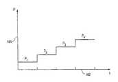
図11は展開工程における図8A−8Cに示されている膨張可能移植片の噴射ポート部分の膨張圧力161と時間162の関係を示すグラフである。P1は導管端移植片内の何れの破裂デイスクも破裂する前の噴射ポートにおける膨張圧力を示している。P2は導管端移植片内の最も弱い破裂デイスクが破損または破裂を生ずるのに必要な圧力を示しており、その後、それまで最も弱い破裂デイスクによりシールされていた導管端移植片の部分が膨張されかつ展開される。時間の経過につれて圧力はP3まで増加し、それは第2の破裂デイスクの破損または爆発を起こすに必要な圧力レベルである。P4は膨張カテーテルの末端部の分離機構を起動するのに必要な圧力レベルである。
【0041】
本発明の特殊な形態が図示されかつ説明されてきたが、本発明の精神と範囲から離れることなく各種の変形が可能なことは明らかであろう。従って、本発明は添付請求の範囲を越えて限定されることは意図されていない。
【図面の簡単な説明】
【図1】 本発明の特徴を有する導管端移植片の斜視図である。
【図2】 一体構造を有する導管端移植片の縦断面図である。
【図3】 図2の導管端移植片縦断面の拡大図である。
【図4】 本発明の特徴を有する導管端移植片の縦断面図である。
【図5】 図4に示されている導管端移植片の部分拡大図である。
【図6】 本発明の特徴を有する二股の導管端移植片の斜視図である。
【図7】 図6の導管端移植片の二股部分の7−7横断面図である。
【図8A−図8C】 本発明の特徴を有する二股導管端移植片の各種展開状態を示す斜視図である。
【図9A】 導管端移植片内の液密室の膨張状態保持のために使用し得るバルブの図8Aの9−9拡大縦断面図である。
【図9B】 導管端移植片内の液密室の膨張状態保持のために使用し得る別シールの図8Aの9−9拡大縦断面図である。
【図9C】 導管端移植片内の液密室の膨張状態保持のために使用し得る別のシールプラグの図8Aの9−9拡大縦断面図である。
【図10】 膨張可能な導管端移植片の膨張順序制御に使用し得る破裂デイスクの図8Cの10−10拡大縦断面図である。
【図11】 本発明の特徴を有する導管端移植片であって予め定められた各種圧力で屈服するように設計された破裂デイスクを包含している膨張可能な導管端移植片の時間に対する膨張圧力のプロット図である。
【符号の説明】
10 導管端移植片
11 基端部
12 末端部
16 膨張可能袖口
18 膨張可能伸長通路
21 可撓性薄層
24 拡張部材
45 基端入口軸
46 入口軸角[0001]
(Technical field)
The present invention relates to systems and methods for the treatment of persons with vasculature disorders. More particularly, the present invention relates to a system and method for the treatment of abdominal aortic aneurysms and the like, where the aortic aneurysm is a condition manifested by swelling and deterioration of the aorta below the diaphragm. Such a condition requires treatment because of the morbidity of sequelae that often leads to death.
[0002]
(Background technology)
The conventional method for treating an aortic aneurysm has been a surgical method in which a graft is embedded in the aorta as a reinforcing member for the artery. However, such procedures require a surgical incision to gain access to the blood vessels, which can lead to a tragic rupture of the aneurysm due to a decrease in external pressure from the organs and tissues surrounding the aorta, This is because the aorta is moved to gain access to the blood vessels during treatment. Thus, surgical procedures result in higher mortality due to the above-described rupture potential, in addition to other factors. Other factors may include blood loss associated with abdominal aortic aneurysms, anuria, and reduced patient health due to hypotension. An example of surgical treatment is described in 1986, W.W. B. Issued by Sanders Company, Denton Coolie M. D. It is described in a book called Surgical Treatment of Aortic Aneurysms.
[0003]
Because of the inherent risks and complexity of surgical procedures, various attempts have been made to develop alternative methods of deploying grafts within an aortic aneurysm. One such method is a non-intrusive technique for transdermal delivery with a catheter-based system. Such a method is described in Lawrence, Jr. Et al., Radiology (May 1987), "Percutaneous Conduit End Graft: Experimental Evaluation". Lawrence describes therein the use of a Giant Turco stent as disclosed in US Pat. No. 4,580,568. This stent is used to place a Dacron fabric graft in a blood vessel. The Dacron graft is compressed within the catheter and then deployed within the conduit to be treated. A similar procedure is described by Mirhi et al. In Radiology (March 1989), “Percutaneously placed conduit end graft for aortic aneurysms: A commercialized study”. Mirhi describes therein a self-expanding metal structure coated with a nylon fabric, the structure being anchored by flipping at the proximal and distal ends.
[0004]
One of the major drawbacks of conventional percutaneous devices and methods is that the graft and the delivery catheter used to deliver the graft are relatively large in profile, often less than or equal to 24 French, and bent Stiff against. Large contours and bending stiffness make it difficult and dangerous for the sick to carry through irregular and tortuous arteries. In particular, arteries near the iliac are often too narrow or irregular as a passage for percutaneous devices. For this reason, non-invasive percutaneous delivery of an implant for the treatment of an aortic aneurysm is not applicable to many patients who would benefit from it.
[0005]
Another contraindication to recent percutaneous graft methods and devices is that the conduit treatment site has a high neck angle where proper fit between the graft and the conduit wall is prevented. Inappropriate fit or seal between the graft and the conduit wall creates a leak or high stress area on the sick's conduit, which results in reduced graft efficiency and the possibility of rupture of the aneurysm .
[0006]
(Disclosure of the Invention)
(Technical problem to be solved by the invention)
While the various methods described above have shown some promise for the treatment of abdominal aortic aneurysms by non-invasive methods, there is a need for a conduit end graft system that can be deployed percutaneously within a small diameter flexible catheter system. It is left. Moreover, there is a need for an implant that is often very irregular and curved and fits better with different aortic aneurysm shapes from patient to patient. The present invention satisfies these and other needs.
[0007]
(Solution)
The present invention is generally directed to conduit end grafts and methods of manufacturing and using the grafts for conduit therapy. The implant includes an inflatable cylindrical frame that is configured to conform to the shape of the patient's conduit to be treated. The frame body has a proximal end and a distal end, and an inflatable cuff is disposed on at least one and preferably both ends. The inflatable cuff may be reduced in diameter and contour when contracted for introduction into a patient's vasculature by a catheter-based delivery system or other suitable means. The inflatable cuff has a sufficiently rigid structure when inflated, which then supports the implant and seals the implant against the inner surface of the conduit in which the implant is deployed. One or more inflatable elongate passages can also be disposed on the implant. Preferably, the elongate passage is disposed between the inflatable proximal cuff and the distal cuff in fluid tight communication with the cuffs. This passage provides the desired stiffness when inflated, prevents twisting of the graft frame, and facilitates deployment of the graft into the patient's body passage. The inflatable elongate passage can be longitudinal or linear with respect to the implant, but is preferably arranged in one spiral with respect to the implant. Other orientations such as interconnected lattices or rings are also suitable for the extension passage. The inflatable cuffs and extension passages are provided with fluid tight chambers that are in fluid communication with each other, which are separated by a valve or rupture disk therein, and selectively in the order of inflation or deployment. You may make it control. Both liquid tight chambers are typically accessible by a jet port, the jet port being configured to receive a pressurized source of gas, fluid, particulates, gel or a composite thereof, and at least one liquid tight chamber And in fluid communication. Fluids that solidify, cure or gel over time can also be used. The number of elongate passages can vary depending on the particular shape of the implant employed for a given instruction, but the number of passages will generally be 1 to 25, preferably 2 to 8.
[0008]
One proximal neck can be secured to the inflatable proximal cuff. The proximal neck includes a single flexible cylinder that has the same diameter as the inflatable proximal cuff. The proximal neck may be formed as a single straight tube, or may be tapered such that the diameter increases or decreases proximally or distally. Preferably, the proximal neck is secured and sealed to an inflatable proximal cuff and a taper that increases in diameter toward the proximal side, thus engaging the inner surface of the conduit wall, which together with the inflatable proximal cuff provides a sealing function. provide. Such a structure also facilitates fluid flow from the patient's conduit to the lumen or passage in the conduit end graft. The proximal neck includes a single entrance shaft, which entrance angle is preferably angularly offset with respect to the longitudinal axis of the implant.
[0009]
Preferably, the implant has a unitary structure in which the material forming the inflatable cuffs and passages extends between these elements in the form of a flexible thin layer through which the thin layer passes. It constitutes a longitudinal lumen that restricts the flow of blood or other fluid. Such monolithic structures can be made of a variety of suitable polymers including PVC, polyurethane, polyethylene and fluoroethylenes such as TFE, PTFE and ePTFE. Additional stiffness or reinforcement to the implant can be increased by adding metal or resin inserts or stiffeners to the implant, such as inserts that position the implant prior to expansion of the expansion portion of the implant. And can also facilitate deployment.
[0010]
In another embodiment, a thin flexible layer is disposed on or between one inflatable proximal cuff and one distal cuff and one inflatable elongated passage in the frame. The flexible thin layer is made of a material that is different from the material of the cuff or elongated passage. The boundary is shaped to form a cylindrical structure that defines a single longitudinal lumen or passage that limits the flow of blood therethrough. The flexible boundary can be made of any suitable material such as a fluoropolymer such as Dacron, Nylon, or Teflon or the like.
[0011]
A conduit end graft having features of the present invention can be made tubular with a flexible layer material such as Dacron, Nylon or the fluoropolymer described above. The inflatable cuff and the elongated passage are formed separately and bonded together. The inflatable cuffs and passages can be made of the same layer material, namely Dacron, Teflon or nylon, with a liquid impermeable membrane or inner bag placed in the cuffs or passages for liquid tightness. In order to limit permeability, the material in the cuff and passage areas can be coated or otherwise processed in a manner such as thermo-mechanical compaction.
[0012]
In one embodiment of the invention, one expansion member is secured to the proximal end of the graft frame or the proximal neck of the graft. The expansion member can also be secured to the distal end of the implant. Preferably, the expansion member is made of a single expandable ring or a plurality of expansion rings of connected shape memory alloy straps, the expansion member being self-expandable and mechanical anchoring to the body passage of the implant. And prevent axial movement once the implant is mounted. By having an expansion member separate from the proximal cuff, the cuff sealing function can be separated from the anchoring function of the expansion member, and the above cuff is a flexible fit to the conduit without applying excessive radial force And the expansion member can provide a large radial force. This allows optimization of each function without compromising the other function. This also allows a throwing function that requires a greater radial force on the conduit wall located more proximally from the aneurysm than the cuff and can therefore be placed in a healthier part of the conduit, The place can withstand the radial force required for the throwing function. In addition, the cuffs and expansion members can be longitudinally separated, at which time the implant is in a collapsed state for delivery, which allows a lower, more flexible profile for percutaneous delivery. With such a structure, the collapsed transport profile can be kept at 12-16 French, preferably less than 12 French.
[0013]
The expandable ring or ring group of expansion members may be formed in a continuous loop with a serpentine or zigzag pattern along the periphery of the ring. Other similar contours that allow radial expansion of the ring may also be used. The expansion member can be made of a suitable high strength metal, such as stainless steel, nitinol or other shape memory alloy, or other suitable high strength composite or polymer. The expansion member can be made of a high plastic resilience material such as Nitinol or a low plastic resilience material such as stainless steel, depending on the contour of the conduit end graft, the configuration of the deployment location, and the delivery and deployment mode of the graft. .
[0014]
The expansion member preferably comprises a single entrance shaft, which forms an entrance shaft angle with respect to the longitudinal axis of the implant. The angled entry shaft allows the implant to better conform to the form of the vasculature of a patient having an angled neck aneurysm configuration. The inlet shaft angle can be about 0 to about 90 degrees, preferably about 20 to about 30 degrees. Some or all of the entrance shaft angles can be configured at the proximal neck of the implant to which the expansion member can be attached. A single expansion member or group of expansion members can be attached to the distal end of the implant.
[0015]
In another embodiment of the invention, the graft is bifurcated at the distal end of the main body portion of the graft and has at least two bifurcated portions having a longitudinal lumen in fluid communication with the longitudinal lumen of the main body portion. I have. The first bifurcated portion and the second bifurcated portion can be formed in the same structure as the main body portion, and have an optional cuff that can be inflated at either the proximal end portion or the distal end portion. One or more elongated passages may be disposed between the inflatable cuffs.
[0016]
Although the size and orientation angle of both bifurcations can vary, they are usually formed to have a single outer diameter that matches the inner diameter of the artery near the patient's iliac bone. The bifurcation may be adapted for use within the patient's renal artery or other suitable indication. The distal end of the bifurcated portion can have an expansion member secured thereto, the purpose of which is the anchoring or expansion, or the anchoring or expansion of the distal end into the body passage to be treated. The expansion member for the distal end of the bifurcated portion may have the same structure as the expansion member fixed to the proximal end portion or the proximal end neck portion of the main body portion. The expansion member is preferably made of a shape memory alloy such as Nitinol.
[0017]
In a bifurcated embodiment of an implant having features of the present invention and having a single inclined proximal end, it forms a single entrance axis angle, the direction of the inclination or angle being that of the implant and deployment site. It may be important for a proper fit between the forms. In general, the angular deviation of the proximal end, proximal neck or proximal expansion member of the graft can be in any direction. Preferably, this angular deviation is orthogonal to a plane defined by the longitudinal axis of the main body portion, the first bifurcated portion and the second bifurcated portion.
[0018]
In another embodiment of the present invention, a rupture disk or other temporary occlusion member is disposed between the inflatable cuff fluid tight chamber and the graft elongate passage or channels to form a seal between the chambers. The rupture disk is ruptured or broken if sufficient force or pressure is applied to one side of the disk or temporary closure member. Once the implant is placed in the patient's body passage to be treated, pressurized gas, fluid or gel can be injected by the dilatation catheter through the injection port into one of the implant's fluid tight chambers. . The cuff can be adapted to the shape of the conduit in which it is deployed, but when pressurized material is injected into the inflatable cuff, the cuff becomes generally annular and sufficient for the inner surface of the body passage to be treated. Exerts a radially outward force and provides the desired sealing function.
[0019]
Multiple rupture disks can be placed at various locations on the implant and can be configured to rupture at different pressures or explosion limits to facilitate deployment of the implant within the body passageway. In a special bifurcated embodiment of the present invention, the inflatable proximal cuff of the main body may be placed at the proximal end of the connection between the patient's abdominal aortic branch and the artery near the iliac. The proximal cuff is deployed by injecting the appropriate material into an injection port that communicates with the fluid tight chamber, so that it expands radially and is fitted axially and sealably into the bifurcated proximal end of the aorta. . A rupture disk is disposed between the liquid tight chamber of the proximal cuff and the inflatable extension passage so that the proximal cuff is substantially before the rupture disk ruptures and the extension passage begins to fill with the injected material. Expanded. The elongated passage then fills and becomes sufficiently rigid and expands to create a longitudinal lumen therein. As the pressure in the liquid tight chamber increases, the rupture disk between the liquid tight chamber of the extension passage and the liquid tight chamber or end manifold of the expandable optional end cuff of the main body ruptures and the expandable end cuff or manifold Deploy and pressurize. One of the bifurcated portions of the graft is deployed as a rupture disk that seals its fluid tight chamber from the inflatable end cuff or manifold of the main body portion of the graft, but ruptures when the inflation pressure increases. Finally, the second bifurcated portion of the implant develops after the rupture disc that seals the liquid tight chamber from the main body portion ruptures.
[0020]
The injection catheter secured to the fluid tight chamber of the implant via an injection port disposed on the implant and in fluid communication is completed after the inflation is completed by raising the pressure above a predetermined value. Can be disconnected from. The rising pressure breaks the connection with the injection port by activating the disconnect mechanism. Alternatively, the dilatation catheter can be unscrewed from its combined state. The injection port can include a check valve, seal or plug to stop the flow of inflation material once the inflation catheter is removed. The injection port is also glued or twisted to block it.
[0021]
An implant having the features of the present invention can be deployed by a transdermal delivery means having a catheter-based system, the system comprising an inflatable balloon member disposed in a deflated state within the expansion member of the implant. ing. The implant is delivered percutaneously to the desired location. Once the implant is axially positioned, the inflatable member of the balloon is expanded and the expansion member is pressed radially outward against the inner surface of the body passage in which it is positioned. The expansion member is self-expanded from the constrained position once the restraint is removed. After the implant is positioned by the catheter system, the inflatable cuff or cuff group and the elongated passage or group of passages of the implant are pressurized.
[0022]
These and other advantages of the present invention will become more apparent from the following detailed description when taken in conjunction with the accompanying exemplary drawings.
[0023]
(Best Mode for Carrying Out the Invention)
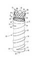
FIG. 1 is a perspective view of a single
[0024]
The distal end of one
[0025]
The
[0026]
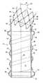
FIG. 2 shows a longitudinal longitudinal section of the conduit end graft shown in FIG. Within the proximal
[0027]
FIG. 3 is an enlarged longitudinal longitudinal sectional view of a part of the
[0028]
FIG. 4 is a cross-sectional view of one embodiment of a conduit end graft having features of the present invention. The inflatable
[0029]
The
[0030]
FIG. 5 is an enlarged longitudinal longitudinal cross-sectional view of the conduit end graft of FIG. Details of the inflatable proximal cuff liquid
[0031]
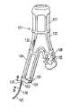
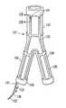
6 and 7 show a
[0032]
The first
[0033]
The second
[0034]
The flexible second
[0035]
8A-8C depict a
[0036]
FIG. 9A shows a 9-9 longitudinal section of FIG. 8A. The one-
[0037]
FIG. 9B shows another one-way valve. The one-
[0038]
FIG. 9C shows another
[0039]
FIG. 10 is a longitudinal section of the
[0040]
FIG. 11 is a graph showing the relationship between inflation pressure 161 and
[0041]
While particular forms of the invention have been illustrated and described, it will be apparent that various modifications can be made without departing from the spirit and scope of the invention. Accordingly, the invention is not intended to be limited beyond the scope of the appended claims.
[Brief description of the drawings]
FIG. 1 is a perspective view of a conduit end graft having features of the present invention.
FIG. 2 is a longitudinal cross-sectional view of a conduit end graft having a unitary structure.
FIG. 3 is an enlarged view of the longitudinal section of the conduit end graft of FIG. 2;
FIG. 4 is a longitudinal cross-sectional view of a conduit end graft having features of the present invention.
5 is a partial enlarged view of the conduit end graft shown in FIG. 4. FIG.
FIG. 6 is a perspective view of a bifurcated conduit end graft having features of the present invention.
7 is a 7-7 cross-sectional view of the bifurcated portion of the conduit end graft of FIG. 6. FIG.
8A-8C are perspective views showing various deployed states of a bifurcated conduit end graft having features of the present invention.
9A is a 9-9 enlarged longitudinal cross-sectional view of FIG. 8A of a valve that can be used to maintain an expanded state of a fluid tight chamber within a conduit end graft.
9B is a 9-9 enlarged longitudinal cross-sectional view of FIG. 8A of another seal that may be used to maintain the expanded state of the fluid tight chamber within the conduit end graft.
9C is a 9-9 enlarged longitudinal cross-sectional view of FIG. 8A of another seal plug that can be used to maintain the expanded state of the fluid tight chamber within the conduit end graft.
FIG. 10 is a 10-10 enlarged longitudinal cross-sectional view of FIG. 8C of a rupture disk that can be used to control the expansion sequence of the expandable conduit end graft.
FIG. 11 is an inflation pressure over time of an inflatable conduit end graft having a feature of the present invention and including a rupture disc designed to yield at various predetermined pressures. FIG.
[Explanation of symbols]
10 Conduit end graft
11 Base end
12 Terminal part
16 Inflatable cuffs
18 Inflatable extension passage
21 Flexible thin layer
24 Expansion member
45 Base inlet shaft
46 Entrance shaft angle
Claims (26)
Translated fromJapanesea)1個の基端部と1個の末端部を有する膨張可能なフレーム体であって、基端部に配置された膨張可能な基端袖口と、膨張可能な基端袖口に連通した少なくとも1個の膨張可能な伸長通路とを備え;
b)膨張可能な基端袖口と、フレームの膨張可能な伸長通路の間に配置されて長手通路を形成する可撓性薄層;および
c)膨張可能な基端袖口の基端に配置され膨張可能なフレーム体の基端でそこから基端側へ延びかつ膨張可能なフレーム体とは独立して半径方向外方への力を及ぼすように構成されている拡張部材を包含している、導管端移植片。Conduit end graft:
a) an inflatable frame having one proximal end and one distal end, an inflatable proximal cuff disposed at the proximal end, and at least communicating with the inflatable proximal cuff One inflatable extension passage;
b) a flexible thin layer disposed between the inflatable proximal cuff and the inflatable elongated passage of the frame to form a longitudinal passage; and c) inflated disposed at the proximal end of the inflatable proximal cuff. A conduit including an expansion member extending proximally therefrom and proximally of the possible frame body and configured to exert a radially outward force independent of the inflatable frame body End graft.
a)1個の主本体部であって、1個の末端部とその上に膨張可能な基端袖口を持つ1個の基端部と、膨張可能な基端袖口の基端に配置され膨張可能なフレーム体の基端でそこから基端側へ延びかつ筒状主ボデー部分とは独立して半径方向外方への力を及ぼすように構成されている拡張部材と、膨張可能な基端袖口と液体連通した少なくとも1個の膨張可能な伸長通路と、膨張可能な基端袖口と膨張可能な伸長通路との間に配置されその中を通る液体流を限定する通路を形成する可撓性薄層とを備えており;
b)移植片が主ボデー部分の末端部で二股状とされかつ、第1および第2の二股筒状部を包含し、各二股部が主本体部の通路と液体連通している構成を包含している、導管端移植片。Conduit end graft:
a) One main body portion, one distal end portion, one proximal end portion having an inflatable proximal cuff thereon, and an inflatable base end portion of the inflatable proximal end cuff An expandable member configured to extend proximally at the proximal end of the possible frame body and to exert a radially outward force independent of the cylindrical main body portion; and an inflatable proximal end Flexibility to form at least one inflatable extension passage in fluid communication with the cuff and a passage disposed between the inflatable proximal cuff and the inflatable extension passage to limit fluid flow therethrough. A thin layer;
b) Includes a configuration in which the graft is bifurcated at the end of the main body portion and includes first and second bifurcated tubular portions, each bifurcated portion being in fluid communication with the passage of the main body portion. A conduit end graft.
a)その上に配置された膨張可能な基端袖口を有する1個の基端部と、
膨張可能な基端袖口の基端に配置され膨張可能なフレーム体の基端でそこから基端側へ延びかつ膨張可能なフレーム体とは独立して半径方向外方への力を及ぼすように構成されている拡張部材と、
1個の末端部と、
膨張可能な基端袖口と液体連通している少なくとも1個の膨張可能な伸長通路と、
主本体部の末端部に配置された第1二股部であって、
その上に配置されている膨張可能な末端袖口を有する1個の末端部と、および
膨張可能な基端袖口と液体連通されている少なくとも1個の膨張可能な伸長通路と、
主本体部の末端部に配置された1個の第2二股部であって、
その上に配置されている膨張可能な末端袖口を有する1個の末端部と、
膨張可能な基端袖口と液体連通している少なくとも1個の膨張可能な伸長通路とを有する1個の主本体部を包含している1個の膨張可能なフレーム体と;
b)膨張可能な基端袖口と、主本体部の膨張可能な伸長通路との間に配置されている可撓性薄層、および第1二股部と第2二股部の膨張可能な末端袖口および膨張可能な伸長通路は二股に分かれた筒状構造を形成するために1個の長手通路を備え、上記部分の夫々を通る血液の流れを限定している構成とを包含している、導管端移植片。Conduit end graft:
a) one proximal end having an inflatable proximal cuff disposed thereon;
Located at the proximal end of the inflatable proximal cuff so as to extend proximally from the inflatable frame body and exert a radially outward force independent of the inflatable frame body A configured expansion member;
One end,
At least one inflatable elongate passage in fluid communication with the inflatable proximal cuff;
A first bifurcated portion disposed at the end of the main body,
A distal end having an inflatable distal cuff disposed thereon, and at least one inflatable elongate passage in fluid communication with the inflatable proximal cuff;
One second bifurcated portion disposed at the end of the main body,
One end having an inflatable end cuff disposed thereon;
An inflatable frame body including a main body having an inflatable proximal cuff and at least one inflatable elongated passage in fluid communication;
b) a flexible thin layer disposed between the inflatable proximal cuff and the inflatable elongate passage of the main body, and the inflatable end cuffs of the first and second forks and An inflatable elongate passage having a longitudinal passage to form a bifurcated tubular structure and including a configuration that restricts blood flow through each of the portions; Graft.
Applications Claiming Priority (5)
| Application Number | Priority Date | Filing Date | Title |
|---|---|---|---|
| US7411298P | 1998-02-09 | 1998-02-09 | |
| US60/074,112 | 1998-02-09 | ||
| US09/133,978US6395019B2 (en) | 1998-02-09 | 1998-08-14 | Endovascular graft |
| US09/133,978 | 1998-08-14 | ||
| PCT/US1999/002698WO1999039662A1 (en) | 1998-02-09 | 1999-02-09 | Endovascular graft |
Related Child Applications (1)
| Application Number | Title | Priority Date | Filing Date |
|---|---|---|---|
| JP2005190044ADivisionJP4303223B2 (en) | 1998-02-09 | 2005-06-29 | Conduit end graft |
Publications (2)
| Publication Number | Publication Date |
|---|---|
| JP2002502629A JP2002502629A (en) | 2002-01-29 |
| JP3792511B2true JP3792511B2 (en) | 2006-07-05 |
Family
ID=26755268
Family Applications (2)
| Application Number | Title | Priority Date | Filing Date |
|---|---|---|---|
| JP2000530166AExpired - LifetimeJP3792511B2 (en) | 1998-02-09 | 1999-02-09 | Conduit end graft |
| JP2005190044AExpired - LifetimeJP4303223B2 (en) | 1998-02-09 | 2005-06-29 | Conduit end graft |
Family Applications After (1)
| Application Number | Title | Priority Date | Filing Date |
|---|---|---|---|
| JP2005190044AExpired - LifetimeJP4303223B2 (en) | 1998-02-09 | 2005-06-29 | Conduit end graft |
Country Status (11)
| Country | Link |
|---|---|
| US (8) | US6395019B2 (en) |
| EP (3) | EP1464301B1 (en) |
| JP (2) | JP3792511B2 (en) |
| AT (1) | ATE269678T1 (en) |
| AU (1) | AU2663699A (en) |
| CA (2) | CA2501892C (en) |
| DE (1) | DE69918272T2 (en) |
| DK (1) | DK1054648T3 (en) |
| ES (1) | ES2220048T3 (en) |
| PT (1) | PT1054648E (en) |
| WO (1) | WO1999039662A1 (en) |
Families Citing this family (254)
| Publication number | Priority date | Publication date | Assignee | Title |
|---|---|---|---|---|
| US5609627A (en)* | 1994-02-09 | 1997-03-11 | Boston Scientific Technology, Inc. | Method for delivering a bifurcated endoluminal prosthesis |
| US6051020A (en)* | 1994-02-09 | 2000-04-18 | Boston Scientific Technology, Inc. | Bifurcated endoluminal prosthesis |
| US5871537A (en)* | 1996-02-13 | 1999-02-16 | Scimed Life Systems, Inc. | Endovascular apparatus |
| GB9713624D0 (en)* | 1997-06-28 | 1997-09-03 | Anson Medical Ltd | Expandable device |
| US6395019B2 (en) | 1998-02-09 | 2002-05-28 | Trivascular, Inc. | Endovascular graft |
| US7491232B2 (en) | 1998-09-18 | 2009-02-17 | Aptus Endosystems, Inc. | Catheter-based fastener implantation apparatus and methods with implantation force resolution |
| DE69933560T2 (en) | 1998-06-19 | 2007-08-30 | Endologix, Inc., Irvine | SELF-EXPANDING, CRUSHING, ENOVOVASCULAR PROSTHESIS |
| US6042597A (en) | 1998-10-23 | 2000-03-28 | Scimed Life Systems, Inc. | Helical stent design |
| US6733523B2 (en)* | 1998-12-11 | 2004-05-11 | Endologix, Inc. | Implantable vascular graft |
| WO2000033769A1 (en)* | 1998-12-11 | 2000-06-15 | Endologix, Inc. | Endoluminal vascular prosthesis |
| US6660030B2 (en) | 1998-12-11 | 2003-12-09 | Endologix, Inc. | Bifurcation graft deployment catheter |
| CA2329213C (en) | 1999-01-22 | 2005-08-09 | Gore Enterprise Holdings, Inc. | Low profile stent and graft combination |
| GB9904722D0 (en)* | 1999-03-03 | 1999-04-21 | Murch Clifford R | A tubular intraluminal graft |
| US8034100B2 (en) | 1999-03-11 | 2011-10-11 | Endologix, Inc. | Graft deployment system |
| US6261316B1 (en) | 1999-03-11 | 2001-07-17 | Endologix, Inc. | Single puncture bifurcation graft deployment system |
| US6258117B1 (en)* | 1999-04-15 | 2001-07-10 | Mayo Foundation For Medical Education And Research | Multi-section stent |
| US6585756B1 (en)* | 1999-05-14 | 2003-07-01 | Ernst P. Strecker | Implantable lumen prosthesis |
| US7892246B2 (en)* | 1999-07-28 | 2011-02-22 | Bioconnect Systems, Inc. | Devices and methods for interconnecting conduits and closing openings in tissue |
| FR2797388B1 (en)* | 1999-08-09 | 2001-11-30 | Novatech Inc | STRUCTURE OF A PROSTHESIS INTENDED TO BE IMPLANTED IN A HUMAN OR ANIMAL DUCT AND PROSTHESIS PROVIDED WITH SUCH A STRUCTURE |
| US6312462B1 (en)* | 1999-09-22 | 2001-11-06 | Impra, Inc. | Prosthesis for abdominal aortic aneurysm repair |
| EP1108400A1 (en)* | 1999-12-13 | 2001-06-20 | Biomedix S.A. | Removable fixation apparatus for a prosthesis in a body vessel |
| US6663667B2 (en)* | 1999-12-29 | 2003-12-16 | Edwards Lifesciences Corporation | Towel graft means for enhancing tissue ingrowth in vascular grafts |
| NL1014095C2 (en)* | 2000-01-17 | 2001-07-18 | Cornelis Hendrikus Anna Witten | Implant valve for implantation into a blood vessel. |
| US6602280B2 (en) | 2000-02-02 | 2003-08-05 | Trivascular, Inc. | Delivery system and method for expandable intracorporeal device |
| CN1268306C (en)* | 2000-02-07 | 2006-08-09 | S&G生物工程株式会社 | Vascular graft and graft guide |
| AU769900B2 (en)* | 2000-03-03 | 2004-02-05 | Cook Medical Technologies Llc | Endovascular device having a stent |
| US6454799B1 (en) | 2000-04-06 | 2002-09-24 | Edwards Lifesciences Corporation | Minimally-invasive heart valves and methods of use |
| US6695833B1 (en)* | 2000-09-27 | 2004-02-24 | Nellix, Inc. | Vascular stent-graft apparatus and forming method |
| US20020042644A1 (en)* | 2000-10-10 | 2002-04-11 | Greenhalgh E. Skott | Bifurcated fabric sleeve stent graft with junction region strengthening elements |
| DE10065824B4 (en) | 2000-12-28 | 2018-10-31 | Jotec Gmbh | Endovascular stent for implantation in the ascending branch of the aorta |
| US6761733B2 (en)* | 2001-04-11 | 2004-07-13 | Trivascular, Inc. | Delivery system and method for bifurcated endovascular graft |
| US9937066B2 (en) | 2001-04-11 | 2018-04-10 | Andre Kerr | Stent/graft assembly |
| US20040138734A1 (en)* | 2001-04-11 | 2004-07-15 | Trivascular, Inc. | Delivery system and method for bifurcated graft |
| US20040215322A1 (en)* | 2001-07-06 | 2004-10-28 | Andrew Kerr | Stent/graft assembly |
| US10105209B2 (en) | 2001-04-11 | 2018-10-23 | Andrew Kerr | Stent/graft assembly |
| US7175651B2 (en)* | 2001-07-06 | 2007-02-13 | Andrew Kerr | Stent/graft assembly |
| US6994722B2 (en)* | 2001-07-03 | 2006-02-07 | Scimed Life Systems, Inc. | Implant having improved fixation to a body lumen and method for implanting the same |
| US7892247B2 (en) | 2001-10-03 | 2011-02-22 | Bioconnect Systems, Inc. | Devices and methods for interconnecting vessels |
| CA2462509A1 (en) | 2001-10-04 | 2003-04-10 | Neovasc Medical Ltd. | Flow reducing implant |
| US7033389B2 (en)* | 2001-10-16 | 2006-04-25 | Scimed Life Systems, Inc. | Tubular prosthesis for external agent delivery |
| US7192441B2 (en)* | 2001-10-16 | 2007-03-20 | Scimed Life Systems, Inc. | Aortic artery aneurysm endovascular prosthesis |
| US20060292206A1 (en) | 2001-11-26 | 2006-12-28 | Kim Steven W | Devices and methods for treatment of vascular aneurysms |
| US8231639B2 (en) | 2001-11-28 | 2012-07-31 | Aptus Endosystems, Inc. | Systems and methods for attaching a prosthesis within a body lumen or hollow organ |
| US20050177180A1 (en) | 2001-11-28 | 2005-08-11 | Aptus Endosystems, Inc. | Devices, systems, and methods for supporting tissue and/or structures within a hollow body organ |
| US20070073389A1 (en) | 2001-11-28 | 2007-03-29 | Aptus Endosystems, Inc. | Endovascular aneurysm devices, systems, and methods |
| US9320503B2 (en) | 2001-11-28 | 2016-04-26 | Medtronic Vascular, Inc. | Devices, system, and methods for guiding an operative tool into an interior body region |
| US20090112303A1 (en)* | 2001-11-28 | 2009-04-30 | Lee Bolduc | Devices, systems, and methods for endovascular staple and/or prosthesis delivery and implantation |
| AU2002353807B2 (en) | 2001-11-28 | 2008-08-14 | Aptus Endosystems, Inc. | Endovascular aneurysm repair system |
| US7147657B2 (en)* | 2003-10-23 | 2006-12-12 | Aptus Endosystems, Inc. | Prosthesis delivery systems and methods |
| US20090138072A1 (en)* | 2001-11-28 | 2009-05-28 | Michael William Gendreau | Devices, systems, and methods for endovascular staple and/or prosthesis delivery and implantation |
| US20100016943A1 (en) | 2001-12-20 | 2010-01-21 | Trivascular2, Inc. | Method of delivering advanced endovascular graft |
| US7125464B2 (en)* | 2001-12-20 | 2006-10-24 | Boston Scientific Santa Rosa Corp. | Method for manufacturing an endovascular graft section |
| EP1465685B1 (en)* | 2001-12-20 | 2010-03-17 | TriVascular2, Inc. | Method and apparatus for manufacturing an endovascular graft section |
| JP4331610B2 (en)* | 2001-12-20 | 2009-09-16 | トリバスキュラー2,インコーポレイティド | Advanced endovascular graft |
| US7147661B2 (en) | 2001-12-20 | 2006-12-12 | Boston Scientific Santa Rosa Corp. | Radially expandable stent |
| US20030236565A1 (en)* | 2002-06-21 | 2003-12-25 | Dimatteo Kristian | Implantable prosthesis |
| US11890181B2 (en)* | 2002-07-22 | 2024-02-06 | Tmt Systems, Inc. | Percutaneous endovascular apparatus for repair of aneurysms and arterial blockages |
| WO2004014257A1 (en)* | 2002-08-08 | 2004-02-19 | Neovasc Medical Ltd. | Geometric flow regulator |
| US7175652B2 (en)* | 2002-08-20 | 2007-02-13 | Cook Incorporated | Stent graft with improved proximal end |
| US7550004B2 (en)* | 2002-08-20 | 2009-06-23 | Cook Biotech Incorporated | Endoluminal device with extracellular matrix material and methods |
| US7335218B2 (en) | 2002-08-28 | 2008-02-26 | Heart Leaflet Technologies, Inc. | Delivery device for leaflet valve |
| US7879085B2 (en) | 2002-09-06 | 2011-02-01 | Boston Scientific Scimed, Inc. | ePTFE crimped graft |
| EP1542616B1 (en) | 2002-09-20 | 2015-04-22 | Endologix, Inc. | Stent-graft with positioning anchor |
| US7481821B2 (en) | 2002-11-12 | 2009-01-27 | Thomas J. Fogarty | Embolization device and a method of using the same |
| US20040260382A1 (en) | 2003-02-12 | 2004-12-23 | Fogarty Thomas J. | Intravascular implants and methods of using the same |
| US7025779B2 (en)* | 2003-02-26 | 2006-04-11 | Scimed Life Systems, Inc. | Endoluminal device having enhanced affixation characteristics |
| US7150758B2 (en)* | 2003-03-06 | 2006-12-19 | Boston Scientific Santa Rosa Corp. | Kink resistant endovascular graft |
| US20050033416A1 (en)* | 2003-05-02 | 2005-02-10 | Jacques Seguin | Vascular graft and deployment system |
| US7632291B2 (en)* | 2003-06-13 | 2009-12-15 | Trivascular2, Inc. | Inflatable implant |
| US20050015140A1 (en)* | 2003-07-14 | 2005-01-20 | Debeer Nicholas | Encapsulation device and methods of use |
| US20050015110A1 (en)* | 2003-07-18 | 2005-01-20 | Fogarty Thomas J. | Embolization device and a method of using the same |
| US20050090804A1 (en)* | 2003-10-22 | 2005-04-28 | Trivascular, Inc. | Endoluminal prosthesis endoleak management |
| US7530994B2 (en)* | 2003-12-30 | 2009-05-12 | Scimed Life Systems, Inc. | Non-porous graft with fastening elements |
| US7803178B2 (en) | 2004-01-30 | 2010-09-28 | Trivascular, Inc. | Inflatable porous implants and methods for drug delivery |
| US8088139B2 (en)* | 2004-02-17 | 2012-01-03 | Boston Scientific Scimed, Inc. | Endoscopic tissue stabilization device and related methods of use |
| JP4852033B2 (en)* | 2004-03-11 | 2012-01-11 | トリバスキュラー インコーポレイテッド | Modular endovascular graft |
| US20050216043A1 (en)* | 2004-03-26 | 2005-09-29 | Blatter Duane D | Stented end graft vessel device for anastomosis and related methods for percutaneous placement |
| US7641686B2 (en)* | 2004-04-23 | 2010-01-05 | Direct Flow Medical, Inc. | Percutaneous heart valve with stentless support |
| CA2563426C (en) | 2004-05-05 | 2013-12-24 | Direct Flow Medical, Inc. | Unstented heart valve with formed in place support structure |
| US7758626B2 (en)* | 2004-07-20 | 2010-07-20 | Medtronic Vascular, Inc. | Device and method for delivering an endovascular stent-graft having a longitudinally unsupported portion |
| US8048145B2 (en) | 2004-07-22 | 2011-11-01 | Endologix, Inc. | Graft systems having filling structures supported by scaffolds and methods for their use |
| ATE540640T1 (en) | 2004-07-22 | 2012-01-15 | Nellix Inc | SYSTEMS FOR THE TREATMENT OF ENDOVASCULAR ANEURYSMS |
| US8403955B2 (en)* | 2004-09-02 | 2013-03-26 | Lifescreen Sciences Llc | Inflatable intravascular filter |
| US7018403B1 (en)* | 2004-09-14 | 2006-03-28 | Advanced Cardiovascular Systems, Inc. | Inclined stent pattern for vulnerable plaque |
| US20070179600A1 (en)* | 2004-10-04 | 2007-08-02 | Gil Vardi | Stent graft including expandable cuff |
| US20060074481A1 (en)* | 2004-10-04 | 2006-04-06 | Gil Vardi | Graft including expandable cuff |
| EP1807022A2 (en)* | 2004-11-03 | 2007-07-18 | Jacques Seguin | Vascular graft and deployment system |
| US8048144B2 (en)* | 2004-11-30 | 2011-11-01 | Scimed Life Systems, Inc. | Prosthesis fixation device and method |
| US20060149364A1 (en)* | 2004-12-31 | 2006-07-06 | Steven Walak | Low profile vascular graft |
| US20060222596A1 (en)* | 2005-04-01 | 2006-10-05 | Trivascular, Inc. | Non-degradable, low swelling, water soluble radiopaque hydrogel polymer |
| US20060224232A1 (en) | 2005-04-01 | 2006-10-05 | Trivascular, Inc. | Hybrid modular endovascular graft |
| US20060233991A1 (en) | 2005-04-13 | 2006-10-19 | Trivascular, Inc. | PTFE layers and methods of manufacturing |
| CA2599460A1 (en) | 2005-04-28 | 2006-11-02 | Nellix, Inc. | Graft systems having filling structures supported by scaffolds and methods for their use |
| CA2610669A1 (en) | 2005-06-07 | 2006-12-14 | Direct Flow Medical, Inc. | Stentless aortic valve replacement with high radial strength |
| JP2009500121A (en) | 2005-07-07 | 2009-01-08 | ネリックス・インコーポレーテッド | System and method for treatment of an intraluminal aneurysm |
| DE102006020687A1 (en)* | 2005-07-19 | 2007-02-08 | Aesculap Ag & Co. Kg | Stent graft prosthesis for treating abdominal aneurisms and aneurisms of the thoracal aorta comprises a sleeve formed as a folding toroid and having a shape in the unfolded state which fits the shape of the aneurism |
| US20070038292A1 (en)* | 2005-08-09 | 2007-02-15 | Moise Danielpour | Bio-absorbable stent |
| US7731741B2 (en) | 2005-09-08 | 2010-06-08 | Boston Scientific Scimed, Inc. | Inflatable bifurcation stent |
| US20070061003A1 (en)* | 2005-09-15 | 2007-03-15 | Cappella, Inc. | Segmented ostial protection device |
| CN101466316B (en) | 2005-10-20 | 2012-06-27 | 阿普特斯内系统公司 | Devices systems and methods for prosthesis delivery and implantation including the use of a fastener tool |
| CA2535552A1 (en)* | 2006-02-03 | 2007-08-03 | Ever D. Grech | Bifurcation stent |
| US7481836B2 (en)* | 2006-03-30 | 2009-01-27 | Medtronic Vascular, Inc. | Prosthesis with coupling zone and methods |
| US7790273B2 (en)* | 2006-05-24 | 2010-09-07 | Nellix, Inc. | Material for creating multi-layered films and methods for making the same |
| US7872068B2 (en)* | 2006-05-30 | 2011-01-18 | Incept Llc | Materials formable in situ within a medical device |
| US8480557B2 (en)* | 2006-07-27 | 2013-07-09 | Refine, Llc | Nonaugmentive mastopexy |
| US9408607B2 (en) | 2009-07-02 | 2016-08-09 | Edwards Lifesciences Cardiaq Llc | Surgical implant devices and methods for their manufacture and use |
| EP3360509B1 (en) | 2006-07-31 | 2022-06-22 | Syntheon TAVR, LLC | Sealable endovascular implants |
| US9585743B2 (en) | 2006-07-31 | 2017-03-07 | Edwards Lifesciences Cardiaq Llc | Surgical implant devices and methods for their manufacture and use |
| US8216297B2 (en)* | 2006-08-14 | 2012-07-10 | Trivascular, Inc. | Dual chamber cuff structure |
| US20080082113A1 (en) | 2006-10-03 | 2008-04-03 | Alure Medical, Inc. | Minimally invasive tissue support |
| US8133213B2 (en) | 2006-10-19 | 2012-03-13 | Direct Flow Medical, Inc. | Catheter guidance through a calcified aortic valve |
| US7935144B2 (en)* | 2006-10-19 | 2011-05-03 | Direct Flow Medical, Inc. | Profile reduction of valve implant |
| US8052732B2 (en)* | 2006-11-14 | 2011-11-08 | Medtronic Vascular, Inc. | Delivery system for stent-graft with anchoring pins |
| US8523931B2 (en) | 2007-01-12 | 2013-09-03 | Endologix, Inc. | Dual concentric guidewire and methods of bifurcated graft deployment |
| US20080188923A1 (en)* | 2007-02-01 | 2008-08-07 | Jack Fa-De Chu | Endovascular devices to protect aneurysmal wall |
| PL2124831T3 (en) | 2007-03-15 | 2017-03-31 | Ortho-Space Ltd. | Prosthetic devices |
| US20080228259A1 (en)* | 2007-03-16 | 2008-09-18 | Jack Fa-De Chu | Endovascular devices and methods to protect aneurysmal wall |
| US20080294237A1 (en)* | 2007-04-04 | 2008-11-27 | Jack Fa-De Chu | Inflatable devices and methods to protect aneurysmal wall |
| US20080255678A1 (en)* | 2007-04-13 | 2008-10-16 | Cully Edward H | Medical apparatus and method of making the same |
| US9717584B2 (en)* | 2007-04-13 | 2017-08-01 | W. L. Gore & Associates, Inc. | Medical apparatus and method of making the same |
| US9642693B2 (en)* | 2007-04-13 | 2017-05-09 | W. L. Gore & Associates, Inc. | Medical apparatus and method of making the same |
| US20080262590A1 (en)* | 2007-04-19 | 2008-10-23 | Medtronic Vascular, Inc. | Delivery System for Stent-Graft |
| WO2009003049A2 (en) | 2007-06-25 | 2008-12-31 | Micro Vention, Inc. | Self-expanding prosthesis |
| US9566178B2 (en) | 2010-06-24 | 2017-02-14 | Edwards Lifesciences Cardiaq Llc | Actively controllable stent, stent graft, heart valve and method of controlling same |
| US9814611B2 (en) | 2007-07-31 | 2017-11-14 | Edwards Lifesciences Cardiaq Llc | Actively controllable stent, stent graft, heart valve and method of controlling same |
| EP2173259A4 (en) | 2007-08-02 | 2015-07-08 | Bio Connect Systems | Implantable flow connector |
| US20130197546A1 (en) | 2007-08-02 | 2013-08-01 | Bioconnect Systems, Inc. | Implantable flow connector |
| WO2009026563A2 (en) | 2007-08-23 | 2009-02-26 | Direct Flow Medical, Inc. | Translumenally implantable heart valve with formed in place support |
| AU2012258319B2 (en)* | 2007-09-13 | 2014-08-14 | W. L. Gore & Associates, Inc. | Stented vascular graft |
| US8906081B2 (en) | 2007-09-13 | 2014-12-09 | W. L. Gore & Associates, Inc. | Stented vascular graft |
| US8066755B2 (en) | 2007-09-26 | 2011-11-29 | Trivascular, Inc. | System and method of pivoted stent deployment |
| US8663309B2 (en) | 2007-09-26 | 2014-03-04 | Trivascular, Inc. | Asymmetric stent apparatus and method |
| BRPI0817566A2 (en)* | 2007-09-26 | 2015-04-07 | Trivascular Inc | Devices and methods of stenting |
| US8226701B2 (en) | 2007-09-26 | 2012-07-24 | Trivascular, Inc. | Stent and delivery system for deployment thereof |
| US10159557B2 (en) | 2007-10-04 | 2018-12-25 | Trivascular, Inc. | Modular vascular graft for low profile percutaneous delivery |
| US8083789B2 (en) | 2007-11-16 | 2011-12-27 | Trivascular, Inc. | Securement assembly and method for expandable endovascular device |
| US8328861B2 (en) | 2007-11-16 | 2012-12-11 | Trivascular, Inc. | Delivery system and method for bifurcated graft |
| US8608792B2 (en)* | 2007-11-30 | 2013-12-17 | Scitech Produtos Medicos Ltda | Endoprosthesis and delivery system for delivering the endoprosthesis within a vessel of a patient |
| BRPI0704464A2 (en)* | 2007-11-30 | 2009-07-28 | Melchiades Da Cunha Neto | endoprosthesis, delivery system within a patient's vessel and uses of said delivery system and said endoprosthesis |
| US8568468B2 (en)* | 2007-12-06 | 2013-10-29 | Cook Medical Technologies Llc | Stent-graft comprising at least one reinforced hole |
| CN101969883B (en)* | 2007-12-26 | 2014-07-30 | 梅德学会公司 | Stent and method of making a stent |
| US7862538B2 (en)* | 2008-02-04 | 2011-01-04 | Incept Llc | Surgical delivery system for medical sealant |
| WO2009105699A1 (en) | 2008-02-22 | 2009-08-27 | Endologix, Inc. | Design and method of placement of a graft or graft system |
| WO2009111802A1 (en)* | 2008-03-07 | 2009-09-11 | Alure Medical, Inc. | Minimally invasive tissue support |
| US8236040B2 (en) | 2008-04-11 | 2012-08-07 | Endologix, Inc. | Bifurcated graft deployment systems and methods |
| EP2278939B1 (en) | 2008-04-25 | 2021-04-14 | Endologix LLC | Stent graft delivery system |
| US10028747B2 (en) | 2008-05-01 | 2018-07-24 | Aneuclose Llc | Coils with a series of proximally-and-distally-connected loops for occluding a cerebral aneurysm |
| US10716573B2 (en) | 2008-05-01 | 2020-07-21 | Aneuclose | Janjua aneurysm net with a resilient neck-bridging portion for occluding a cerebral aneurysm |
| US20090281634A1 (en)* | 2008-05-08 | 2009-11-12 | The University Of Mississippi Medical Center Research Development Foundation | Gut prosthetic |
| US20100305686A1 (en)* | 2008-05-15 | 2010-12-02 | Cragg Andrew H | Low-profile modular abdominal aortic aneurysm graft |
| EP2299931B1 (en) | 2008-06-04 | 2020-01-08 | Endologix, Inc. | Sealing apparatus |
| PL4223257T3 (en) | 2008-06-06 | 2024-09-23 | Edwards Lifesciences Corporation | LOW-PROFILE TRANSCATHETIC HEART VALVE |
| EP2520320B1 (en) | 2008-07-01 | 2016-11-02 | Endologix, Inc. | Catheter system |
| US20100010518A1 (en)* | 2008-07-09 | 2010-01-14 | Joshua Stopek | Anastomosis Sheath And Method Of Use |
| WO2010006243A2 (en)* | 2008-07-10 | 2010-01-14 | Atrial Systems, Llc | Endovascular conduit device for increasing safety of cardiac lead extraction and other vascular procedures |
| US8454680B2 (en)* | 2008-07-10 | 2013-06-04 | Atrial Systems, Llc | Endovascular conduit device with low profile occlusion members |
| WO2010044854A1 (en)* | 2008-10-16 | 2010-04-22 | Aptus Endosystems, Inc. | Devices, systems, and methods for endovascular staple and/or prosthesis delivery and implantation |
| CA2740867C (en) | 2008-10-16 | 2018-06-12 | Aptus Endosystems, Inc. | Devices, systems, and methods for endovascular staple and/or prosthesis delivery and implantation |
| EP2352435B1 (en)* | 2008-10-31 | 2019-11-27 | Sinclair Pharmaceuticals Limited | Minimally invasive tissue support system with a superior tissue support and an inferior anchor |
| US20110054587A1 (en) | 2009-04-28 | 2011-03-03 | Endologix, Inc. | Apparatus and method of placement of a graft or graft system |
| JP2012525239A (en) | 2009-05-01 | 2012-10-22 | エンドロジックス、インク | Transcutaneous methods and devices for treating dissociation (priority information and incorporation by reference) |
| US10772717B2 (en) | 2009-05-01 | 2020-09-15 | Endologix, Inc. | Percutaneous method and device to treat dissections |
| WO2011008989A2 (en) | 2009-07-15 | 2011-01-20 | Endologix, Inc. | Stent graft |
| WO2011017123A2 (en) | 2009-07-27 | 2011-02-10 | Endologix, Inc. | Stent graft |
| GB2472603B (en)* | 2009-08-11 | 2011-12-14 | Cook Medical Technologies Llc | Implantable medical device |
| US9358140B1 (en) | 2009-11-18 | 2016-06-07 | Aneuclose Llc | Stent with outer member to embolize an aneurysm |
| EP2506799A4 (en)* | 2009-12-01 | 2014-10-29 | Altura Medical Inc | Modular endograft devices and associated systems and methods |
| US20110276078A1 (en) | 2009-12-30 | 2011-11-10 | Nellix, Inc. | Filling structure for a graft system and methods of use |
| US20110218609A1 (en)* | 2010-02-10 | 2011-09-08 | Trivascular, Inc. | Fill tube manifold and delivery methods for endovascular graft |
| US8454682B2 (en) | 2010-04-13 | 2013-06-04 | Medtronic Vascular, Inc. | Anchor pin stent-graft delivery system |
| US9433501B2 (en) | 2010-05-19 | 2016-09-06 | Direct Flow Medical, Inc. | Inflation media for implants |
| US9603708B2 (en) | 2010-05-19 | 2017-03-28 | Dfm, Llc | Low crossing profile delivery catheter for cardiovascular prosthetic implant |
| US8696738B2 (en) | 2010-05-20 | 2014-04-15 | Maquet Cardiovascular Llc | Composite prosthesis with external polymeric support structure and methods of manufacturing the same |
| US8961501B2 (en) | 2010-09-17 | 2015-02-24 | Incept, Llc | Method for applying flowable hydrogels to a cornea |
| WO2012040240A1 (en) | 2010-09-20 | 2012-03-29 | Altura Medical, Inc. | Stent graft delivery systems and associated methods |
| US20120109279A1 (en) | 2010-11-02 | 2012-05-03 | Endologix, Inc. | Apparatus and method of placement of a graft or graft system |
| EP2640319B1 (en) | 2010-11-16 | 2016-10-19 | TriVascular, Inc. | Advanced endovascular graft and delivery system |
| US9393100B2 (en) | 2010-11-17 | 2016-07-19 | Endologix, Inc. | Devices and methods to treat vascular dissections |
| US20120179097A1 (en)* | 2011-01-06 | 2012-07-12 | Cully Edward H | Methods and apparatus for an adjustable stiffness catheter |
| US8801768B2 (en) | 2011-01-21 | 2014-08-12 | Endologix, Inc. | Graft systems having semi-permeable filling structures and methods for their use |
| US8808350B2 (en) | 2011-03-01 | 2014-08-19 | Endologix, Inc. | Catheter system and methods of using same |
| EP2693980B1 (en) | 2011-04-06 | 2022-07-13 | Endologix LLC | System for endovascular aneurysm treatment |
| FR2975000B1 (en)* | 2011-05-10 | 2013-06-14 | Guro Bjoernstad | VASCULAR ENDOPROSTHESIS |
| US10335296B2 (en) | 2011-05-17 | 2019-07-02 | The University Of Kentucky Research Foundation | Graft within a graft endoluminal graft |
| US8636810B2 (en)* | 2011-09-28 | 2014-01-28 | Ethicon, Inc. | Negative pressure intestinal anastomosis protection devices |
| US8978448B2 (en) | 2011-10-11 | 2015-03-17 | Trivascular, Inc. | In vitro testing of endovascular device |
| US9289307B2 (en) | 2011-10-18 | 2016-03-22 | Ortho-Space Ltd. | Prosthetic devices and methods for using same |
| US9827093B2 (en) | 2011-10-21 | 2017-11-28 | Edwards Lifesciences Cardiaq Llc | Actively controllable stent, stent graft, heart valve and method of controlling same |
| US8992595B2 (en) | 2012-04-04 | 2015-03-31 | Trivascular, Inc. | Durable stent graft with tapered struts and stable delivery methods and devices |
| US9498363B2 (en) | 2012-04-06 | 2016-11-22 | Trivascular, Inc. | Delivery catheter for endovascular device |
| US10434293B2 (en) | 2012-04-15 | 2019-10-08 | Tva Medical, Inc. | Implantable flow connector |
| US9314600B2 (en) | 2012-04-15 | 2016-04-19 | Bioconnect Systems, Inc. | Delivery system for implantable flow connector |
| US9445897B2 (en) | 2012-05-01 | 2016-09-20 | Direct Flow Medical, Inc. | Prosthetic implant delivery device with introducer catheter |
| US9132025B2 (en) | 2012-06-15 | 2015-09-15 | Trivascular, Inc. | Bifurcated endovascular prosthesis having tethered contralateral leg |
| US9066828B2 (en) | 2012-06-15 | 2015-06-30 | Trivascular, Inc. | Endovascular delivery system with flexible and torqueable hypotube |
| US9233015B2 (en) | 2012-06-15 | 2016-01-12 | Trivascular, Inc. | Endovascular delivery system with an improved radiopaque marker scheme |
| CA2881535A1 (en) | 2012-08-10 | 2014-02-13 | Altura Medical, Inc. | Stent delivery systems and associated methods |
| WO2014045428A1 (en)* | 2012-09-24 | 2014-03-27 | テルモ株式会社 | Indwelling device |
| US20140194973A1 (en) | 2013-01-10 | 2014-07-10 | Trivascular, Inc. | Sac liner for aneurysm repair |
| WO2014110254A1 (en) | 2013-01-10 | 2014-07-17 | Trivascular, Inc. | Gate wire for contralateral leg access |
| US9655754B2 (en) | 2013-01-10 | 2017-05-23 | Trivascular, Inc. | Systems and methods for guidewire crossover for bifurcated prostheses |
| US10327778B2 (en)* | 2013-02-28 | 2019-06-25 | Boston Scientific Scimed, Inc. | Stent with balloon for repair of anastomosis surgery leaks |
| US9839543B2 (en)* | 2013-03-14 | 2017-12-12 | Cook Medical Technologies Llc | Multi-stage balloon catheter |
| BR112015022688B1 (en) | 2013-03-14 | 2020-10-06 | Endologix, Inc. | METHOD FOR FORMING A MATERIAL IN SITU THROUGH INCREASING THE VOLUME OF AN EXPANDABLE MEMBER OF A MEDICAL DEVICE |
| WO2014144809A1 (en) | 2013-03-15 | 2014-09-18 | Altura Medical, Inc. | Endograft device delivery systems and associated methods |
| US9907684B2 (en) | 2013-05-08 | 2018-03-06 | Aneuclose Llc | Method of radially-asymmetric stent expansion |
| CN105979913B (en) | 2013-06-05 | 2018-09-14 | 俄奥梯科创新有限公司 | Variable sunken holder(VDS)It is grafted component with waveform |
| US11123205B2 (en)* | 2013-09-24 | 2021-09-21 | Trivascular, Inc. | Tandem modular endograft |
| CN104586537B (en)* | 2013-10-31 | 2017-05-10 | 微创心脉医疗科技(上海)有限公司 | Covered stent |
| WO2015105530A1 (en) | 2014-01-09 | 2015-07-16 | Trivascular, Inc. | Systems and methods for guidewire crossover for bifurcated prostheses |
| JP6959003B2 (en) | 2014-03-10 | 2021-11-02 | トリバスキュラー インコーポレイテッド | Inflatable occlusion wire balloon for aortic applications |
| KR101628711B1 (en)* | 2014-06-26 | 2016-06-09 | 주식회사 에스앤지바이오텍 | Stent With External Flow Path |
| US10849774B2 (en) | 2014-10-23 | 2020-12-01 | Trivascular, Inc. | Stent graft delivery system with access conduit |
| WO2016090112A1 (en) | 2014-12-04 | 2016-06-09 | Trivascular, Inc. | Internal iliac preservation devices and methods |
| US10166126B2 (en) | 2014-12-08 | 2019-01-01 | Boston Scientific Scimed, Inc. | Inflatable balloon stent |
| RU2580168C1 (en)* | 2015-02-20 | 2016-04-10 | Игорь Валерьевич Михайлов | Article for formation of stent and method for formation thereof |
| CN107530162B (en) | 2015-05-11 | 2020-01-24 | 曲瓦斯库勒股份有限公司 | Stent graft with improved flexibility |
| JP6803340B2 (en) | 2015-05-27 | 2020-12-23 | トリバスキュラー・インコーポレイテッドTriVascular, INC. | Balloon support intraluminal prosthesis deployment |
| WO2017004265A1 (en) | 2015-06-30 | 2017-01-05 | Endologix, Inc. | Locking assembly for coupling guidewire to delivery system |
| JP7083249B2 (en) | 2015-07-30 | 2022-06-10 | トリバスキュラー・インコーポレイテッド | Intraluminal prosthesis deployment device and method |
| US20170042551A1 (en)* | 2015-08-13 | 2017-02-16 | The Brain Protection Company PTY LTD | Implantable damping devices for treating dementia and associated systems and methods of use |
| WO2017046647A1 (en) | 2015-09-18 | 2017-03-23 | Ortho-Space Ltd. | Intramedullary fixated subacromial spacers |
| US20170281331A1 (en)* | 2016-03-31 | 2017-10-05 | Medtronic Vascular, Inc. | Endoluminal prosthetic devices having fluid-absorbable compositions for repair of a vascular tissue defect |
| WO2017222875A1 (en) | 2016-06-21 | 2017-12-28 | Medtronic Vascular Inc. | Coated endovascular prostheses for aneurism treatment |
| US11376121B2 (en) | 2016-11-04 | 2022-07-05 | Highlife Sas | Transcatheter valve prosthesis |
| US10188514B2 (en) | 2016-11-04 | 2019-01-29 | Highlife Sas | Transcatheter valve prosthesis |
| US10456247B2 (en) | 2016-11-04 | 2019-10-29 | Highlife Sas | Transcatheter valve prosthesis |
| US9999502B2 (en) | 2016-11-04 | 2018-06-19 | Highlife Sas | Transcather valve prosthesis |
| US10195027B2 (en) | 2016-11-04 | 2019-02-05 | Highlife Sas | Transcatheter valve prosthesis |
| US11406522B2 (en)* | 2016-11-09 | 2022-08-09 | Boston Scientific Scimed, Inc. | Deployable sleeves and related methods |
| EP3538031A1 (en) | 2016-11-09 | 2019-09-18 | Boston Scientific Scimed, Inc. | Stent including displacement capabilities |
| EP3573806A4 (en) | 2017-01-30 | 2019-12-11 | Ortho-Space Ltd. | Processing machine and methods for processing dip-molded articles |
| US11883273B2 (en)* | 2017-04-28 | 2024-01-30 | Regents Of The University Of Minnesota | Compliant aortic stent grafts and related systems and methods |
| CA3066361A1 (en) | 2017-06-07 | 2018-12-13 | Shifamed Holdings, Llc | Intravascular fluid movement devices, systems, and methods of use |
| US11051824B2 (en)* | 2017-09-28 | 2021-07-06 | Microvention, Inc. | Embolic delivery |
| WO2019094963A1 (en) | 2017-11-13 | 2019-05-16 | Shifamed Holdings, Llc | Intravascular fluid movement devices, systems, and methods of use |
| US10517713B2 (en) | 2018-01-10 | 2019-12-31 | Cook Medical Technologies Llc | Vascular graft with helical flow compliance compartments |
| US10893929B2 (en)* | 2018-01-10 | 2021-01-19 | Cook Medical Technologies Llc | Vascular graft with compartments for compliance matching |
| CN112004563B (en) | 2018-02-01 | 2024-08-06 | 施菲姆德控股有限责任公司 | Intravascular blood pump and methods of use and manufacture |
| US12161857B2 (en) | 2018-07-31 | 2024-12-10 | Shifamed Holdings, Llc | Intravascular blood pumps and methods of use |
| WO2020073047A1 (en) | 2018-10-05 | 2020-04-09 | Shifamed Holdings, Llc | Intravascular blood pumps and methods of use |
| CN109431650B (en)* | 2018-11-27 | 2021-08-17 | 深圳市先健畅通医疗有限公司 | Covered stent |
| WO2020117562A1 (en) | 2018-12-04 | 2020-06-11 | The Brain Protection Company PTY LTD | Combinatorial therapies including implantable damping devices and therapeutic agents for treating a condition and associated systems and methods of use |
| CN113891686B (en) | 2019-01-23 | 2024-12-27 | 冲击波医疗公司 | Flow changing device with cover |
| AU2020211601B2 (en)* | 2019-01-24 | 2023-08-17 | Shockwave Medical, Inc. | Flow modifying implants |
| US11672681B2 (en)* | 2019-01-28 | 2023-06-13 | Mubin I. Syed | Variable flow stent |
| WO2021011473A1 (en) | 2019-07-12 | 2021-01-21 | Shifamed Holdings, Llc | Intravascular blood pumps and methods of manufacture and use |
| US11654275B2 (en) | 2019-07-22 | 2023-05-23 | Shifamed Holdings, Llc | Intravascular blood pumps with struts and methods of use and manufacture |
| EP4501393A3 (en) | 2019-09-25 | 2025-04-09 | Shifamed Holdings, LLC | Catheter blood pumps and collapsible pump housings |
| WO2021062265A1 (en) | 2019-09-25 | 2021-04-01 | Shifamed Holdings, Llc | Intravascular blood pump systems and methods of use and control thereof |
| US12121713B2 (en) | 2019-09-25 | 2024-10-22 | Shifamed Holdings, Llc | Catheter blood pumps and collapsible blood conduits |
| EP4072650A4 (en) | 2019-12-11 | 2024-01-10 | Shifamed Holdings, LLC | Descending aorta and vena cava blood pumps |
| US11786355B2 (en) | 2020-01-30 | 2023-10-17 | Boston Scientific Scimed, Inc. | Radial adjusting self-expanding stent with anti-migration features |
| WO2021231574A1 (en)* | 2020-05-12 | 2021-11-18 | Shifamed Holdings, Llc | Inflatable medical devices, methods of manufacture and use |
Family Cites Families (494)
| Publication number | Priority date | Publication date | Assignee | Title |
|---|---|---|---|---|
| US3540431A (en) | 1968-04-04 | 1970-11-17 | Kazi Mobin Uddin | Collapsible filter for fluid flowing in closed passageway |
| US3631854A (en) | 1969-05-19 | 1972-01-04 | Robert Howard Fryer | Inflatable medical assemblies |
| US3657744A (en) | 1970-05-08 | 1972-04-25 | Univ Minnesota | Method for fixing prosthetic implants in a living body |
| CA962021A (en) | 1970-05-21 | 1975-02-04 | Robert W. Gore | Porous products and process therefor |
| US3991797A (en) | 1970-10-03 | 1976-11-16 | Seitz-Werke Gmbh | Rinsing device for circulating one-chamber vessel filling machines |
| US3818511A (en) | 1972-11-17 | 1974-06-25 | Medical Prod Corp | Medical prosthesis for ducts or conduits |
| US3814137A (en) | 1973-01-26 | 1974-06-04 | Baxter Laboratories Inc | Injection site for flow conduits containing biological fluids |
| US3991767A (en)* | 1973-11-02 | 1976-11-16 | Cutter Laboratories, Inc. | Tubular unit with vessel engaging cuff structure |
| US3900027A (en) | 1974-01-02 | 1975-08-19 | Pall Corp | Process for preparing integral absorbent pad bandages and product |
| US3902198A (en) | 1974-05-20 | 1975-09-02 | Gore & Ass | Method of replacing a body part with expanded porous polytetrafluoroethylene |
| US6436135B1 (en) | 1974-10-24 | 2002-08-20 | David Goldfarb | Prosthetic vascular graft |
| US4374669A (en) | 1975-05-09 | 1983-02-22 | Mac Gregor David C | Cardiovascular prosthetic devices and implants with porous systems |
| US4208745A (en) | 1976-01-21 | 1980-06-24 | Sumitomo Electric Industries, Ltd. | Vascular prostheses composed of polytetrafluoroethylene and process for their production |
| DE2760437C2 (en) | 1976-04-05 | 1990-03-22 | Agence Nationale De Valorisation De La Recherche (Anvar), Paris, Fr | |
| US4140126A (en) | 1977-02-18 | 1979-02-20 | Choudhury M Hasan | Method for performing aneurysm repair |
| US4183102A (en) | 1977-09-08 | 1980-01-15 | Jacques Guiset | Inflatable prosthetic device for lining a body duct |
| DE2806030C2 (en) | 1978-02-14 | 1984-02-02 | B. Braun Melsungen Ag, 3508 Melsungen | Process for the production of a tubular blood vessel prosthesis |
| SE424045B (en) | 1979-01-12 | 1982-06-28 | Tesi Ab | CATHETER |
| US4214587A (en) | 1979-02-12 | 1980-07-29 | Sakura Chester Y Jr | Anastomosis device and method |
| US4604762A (en) | 1981-02-13 | 1986-08-12 | Thoratec Laboratories Corporation | Arterial graft prosthesis |
| SE445884B (en) | 1982-04-30 | 1986-07-28 | Medinvent Sa | DEVICE FOR IMPLANTATION OF A RODFORM PROTECTION |
| GB2121286B (en) | 1982-06-02 | 1985-11-06 | Ethicon Inc | Improvements in synthetic vascular grafts, and methods of manufacturing such grafts |
| US4512338A (en) | 1983-01-25 | 1985-04-23 | Balko Alexander B | Process for restoring patency to body vessels |
| US4647416A (en) | 1983-08-03 | 1987-03-03 | Shiley Incorporated | Method of preparing a vascular graft prosthesis |
| US4550447A (en) | 1983-08-03 | 1985-11-05 | Shiley Incorporated | Vascular graft prosthesis |
| US4592754A (en) | 1983-09-09 | 1986-06-03 | Gupte Pradeep M | Surgical prosthetic vessel graft and catheter combination and method |
| US4665906A (en) | 1983-10-14 | 1987-05-19 | Raychem Corporation | Medical devices incorporating sim alloy elements |
| US5190546A (en) | 1983-10-14 | 1993-03-02 | Raychem Corporation | Medical devices incorporating SIM alloy elements |
| US5275622A (en) | 1983-12-09 | 1994-01-04 | Harrison Medical Technologies, Inc. | Endovascular grafting apparatus, system and method and devices for use therewith |
| US5669936A (en) | 1983-12-09 | 1997-09-23 | Endovascular Technologies, Inc. | Endovascular grafting system and method for use therewith |
| US5693083A (en) | 1983-12-09 | 1997-12-02 | Endovascular Technologies, Inc. | Thoracic graft and delivery catheter |
| US4787899A (en) | 1983-12-09 | 1988-11-29 | Lazarus Harrison M | Intraluminal graft device, system and method |
| US5749920A (en) | 1983-12-09 | 1998-05-12 | Endovascular Technologies, Inc. | Multicapsule intraluminal grafting system and method |
| US5104399A (en) | 1986-12-10 | 1992-04-14 | Endovascular Technologies, Inc. | Artificial graft and implantation method |
| US6221102B1 (en) | 1983-12-09 | 2001-04-24 | Endovascular Technologies, Inc. | Intraluminal grafting system |
| US5108424A (en) | 1984-01-30 | 1992-04-28 | Meadox Medicals, Inc. | Collagen-impregnated dacron graft |
| US4562596A (en) | 1984-04-25 | 1986-01-07 | Elliot Kornberg | Aortic graft, device and method for performing an intraluminal abdominal aortic aneurysm repair |
| US4617932A (en) | 1984-04-25 | 1986-10-21 | Elliot Kornberg | Device and method for performing an intraluminal abdominal aortic aneurysm repair |
| US4580568A (en) | 1984-10-01 | 1986-04-08 | Cook, Incorporated | Percutaneous endovascular stent and method for insertion thereof |
| US4655769A (en) | 1984-10-24 | 1987-04-07 | Zachariades Anagnostis E | Ultra-high-molecular-weight polyethylene products including vascular prosthesis devices and methods relating thereto and employing pseudo-gel states |
| US4577631A (en) | 1984-11-16 | 1986-03-25 | Kreamer Jeffry W | Aneurysm repair apparatus and method |
| US4705517A (en) | 1985-09-03 | 1987-11-10 | Becton, Dickinson And Company | Percutaneously deliverable intravascular occlusion prosthesis |
| US4733665C2 (en) | 1985-11-07 | 2002-01-29 | Expandable Grafts Partnership | Expandable intraluminal graft and method and apparatus for implanting an expandable intraluminal graft |
| US4740207A (en) | 1986-09-10 | 1988-04-26 | Kreamer Jeffry W | Intralumenal graft |
| JPH0696023B2 (en) | 1986-11-10 | 1994-11-30 | 宇部日東化成株式会社 | Artificial blood vessel and method for producing the same |
| US4816028A (en) | 1987-07-01 | 1989-03-28 | Indu Kapadia | Woven vascular graft |
| US4830003A (en) | 1988-06-17 | 1989-05-16 | Wolff Rodney G | Compressive stent and delivery system |
| US5226913A (en) | 1988-09-01 | 1993-07-13 | Corvita Corporation | Method of making a radially expandable prosthesis |
| US5019090A (en) | 1988-09-01 | 1991-05-28 | Corvita Corporation | Radially expandable endoprosthesis and the like |
| CA1322628C (en) | 1988-10-04 | 1993-10-05 | Richard A. Schatz | Expandable intraluminal graft |
| US4856516A (en) | 1989-01-09 | 1989-08-15 | Cordis Corporation | Endovascular stent apparatus and method |
| US4902423A (en) | 1989-02-02 | 1990-02-20 | W. L. Gore & Associates, Inc. | Highly air permeable expanded polytetrafluoroethylene membranes and process for making them |
| US4957669A (en) | 1989-04-06 | 1990-09-18 | Shiley, Inc. | Method for producing tubing useful as a tapered vascular graft prosthesis |
| US5100422A (en) | 1989-05-26 | 1992-03-31 | Impra, Inc. | Blood vessel patch |
| US5104400A (en) | 1989-05-26 | 1992-04-14 | Impra, Inc. | Blood vessel patch |
| US4955899A (en) | 1989-05-26 | 1990-09-11 | Impra, Inc. | Longitudinally compliant vascular graft |
| US5152782A (en) | 1989-05-26 | 1992-10-06 | Impra, Inc. | Non-porous coated ptfe graft |
| US5609626A (en) | 1989-05-31 | 1997-03-11 | Baxter International Inc. | Stent devices and support/restrictor assemblies for use in conjunction with prosthetic vascular grafts |
| US5171262A (en) | 1989-06-15 | 1992-12-15 | Cordis Corporation | Non-woven endoprosthesis |
| US5207695A (en) | 1989-06-19 | 1993-05-04 | Trout Iii Hugh H | Aortic graft, implantation device, and method for repairing aortic aneurysm |
| WO1991000792A1 (en) | 1989-07-06 | 1991-01-24 | Ramset Fasteners (Aust.) Pty. Limited | Aligning members |
| GB8927282D0 (en) | 1989-12-01 | 1990-01-31 | Univ Strathclyde | Vascular surgical devices |
| DK0441516T3 (en) | 1990-02-08 | 1995-06-12 | Howmedica | Inflatable catheter |
| US5344426A (en) | 1990-04-25 | 1994-09-06 | Advanced Cardiovascular Systems, Inc. | Method and system for stent delivery |
| US5123917A (en) | 1990-04-27 | 1992-06-23 | Lee Peter Y | Expandable intraluminal vascular graft |
| US5360443A (en) | 1990-06-11 | 1994-11-01 | Barone Hector D | Aortic graft for repairing an abdominal aortic aneurysm |
| US5578071A (en) | 1990-06-11 | 1996-11-26 | Parodi; Juan C. | Aortic graft |
| US5064435A (en) | 1990-06-28 | 1991-11-12 | Schneider (Usa) Inc. | Self-expanding prosthesis having stable axial length |
| US5405379A (en) | 1990-07-26 | 1995-04-11 | Lane; Rodney J. | Self expanding vascular endoprosthesis for aneurysms |
| US5122154A (en) | 1990-08-15 | 1992-06-16 | Rhodes Valentine J | Endovascular bypass graft |
| US5139480A (en) | 1990-08-22 | 1992-08-18 | Biotech Laboratories, Inc. | Necking stents |
| US5234447A (en) | 1990-08-28 | 1993-08-10 | Robert L. Kaster | Side-to-end vascular anastomotic staple apparatus |
| AR246020A1 (en) | 1990-10-03 | 1994-03-30 | Hector Daniel Barone Juan Carl | A ball device for implanting an intraluminous aortic prosthesis, for repairing aneurysms. |
| DE9117152U1 (en) | 1990-10-09 | 1996-07-11 | Cook Inc., Bloomington, Ind. | Stent |
| US5156620A (en) | 1991-02-04 | 1992-10-20 | Pigott John P | Intraluminal graft/stent and balloon catheter for insertion thereof |
| US5171252A (en) | 1991-02-05 | 1992-12-15 | Friedland Thomas W | Surgical fastening clip formed of a shape memory alloy, a method of making such a clip and a method of using such a clip |
| DE4104702C2 (en) | 1991-02-15 | 1996-01-18 | Malte Neuss | Implants for organ pathways in spiral form |
| US5116365A (en) | 1991-02-22 | 1992-05-26 | Cordis Corporation | Stent apparatus and method for making |
| US5282847A (en) | 1991-02-28 | 1994-02-01 | Medtronic, Inc. | Prosthetic vascular grafts with a pleated structure |
| US5628783A (en) | 1991-04-11 | 1997-05-13 | Endovascular Technologies, Inc. | Bifurcated multicapsule intraluminal grafting system and method |
| CA2065634C (en) | 1991-04-11 | 1997-06-03 | Alec A. Piplani | Endovascular graft having bifurcation and apparatus and method for deploying the same |
| JPH07500122A (en) | 1991-06-14 | 1995-01-05 | ダブリュ.エル.ゴア アンド アソシエーツ,インコーポレイティド | Surface-modified porous expanded expanded polytetrafluoroethylene and its manufacturing method |
| NL9101159A (en) | 1991-07-03 | 1993-02-01 | Industrial Res Bv | FORMATTABLE EXPANDABLE RING, CYLINDER OR SLEEVE. |
| US5411550A (en) | 1991-09-16 | 1995-05-02 | Atrium Medical Corporation | Implantable prosthetic device for the delivery of a bioactive material |
| US5197976A (en) | 1991-09-16 | 1993-03-30 | Atrium Medical Corporation | Manually separable multi-lumen vascular graft |
| US5443498A (en) | 1991-10-01 | 1995-08-22 | Cook Incorporated | Vascular stent and method of making and implanting a vacsular stent |
| US5500013A (en) | 1991-10-04 | 1996-03-19 | Scimed Life Systems, Inc. | Biodegradable drug delivery vascular stent |
| US5151105A (en) | 1991-10-07 | 1992-09-29 | Kwan Gett Clifford | Collapsible vessel sleeve implant |
| US5366504A (en) | 1992-05-20 | 1994-11-22 | Boston Scientific Corporation | Tubular medical prosthesis |
| US5662713A (en) | 1991-10-09 | 1997-09-02 | Boston Scientific Corporation | Medical stents for body lumens exhibiting peristaltic motion |
| US5290305A (en) | 1991-10-11 | 1994-03-01 | Kanji Inoue | Appliance collapsible for insertion into human organs and capable of resilient restoration |
| US5338295A (en) | 1991-10-15 | 1994-08-16 | Scimed Life Systems, Inc. | Dilatation catheter with polyimide-encased stainless steel braid proximal shaft |
| JP3356447B2 (en) | 1991-10-16 | 2002-12-16 | テルモ株式会社 | Vascular lesion embolic material composed of dried polymer gel |
| US5456713A (en) | 1991-10-25 | 1995-10-10 | Cook Incorporated | Expandable transluminal graft prosthesis for repairs of aneurysm and method for implanting |
| US5387235A (en) | 1991-10-25 | 1995-02-07 | Cook Incorporated | Expandable transluminal graft prosthesis for repair of aneurysm |
| US5720776A (en) | 1991-10-25 | 1998-02-24 | Cook Incorporated | Barb and expandable transluminal graft prosthesis for repair of aneurysm |
| US5693084A (en) | 1991-10-25 | 1997-12-02 | Cook Incorporated | Expandable transluminal graft prosthesis for repair of aneurysm |
| CA2081424C (en) | 1991-10-25 | 2008-12-30 | Timothy A. Chuter | Expandable transluminal graft prosthesis for repair of aneurysm |
| CA2079417C (en) | 1991-10-28 | 2003-01-07 | Lilip Lau | Expandable stents and method of making same |
| FR2683449A1 (en) | 1991-11-08 | 1993-05-14 | Cardon Alain | ENDOPROTHESIS FOR TRANSLUMINAL IMPLANTATION. |
| JP3191964B2 (en) | 1991-12-11 | 2001-07-23 | 有限会社日本総合医学研究所 | Internal fixation type artificial blood vessel and transplantation set including the same |
| US5316023A (en) | 1992-01-08 | 1994-05-31 | Expandable Grafts Partnership | Method for bilateral intra-aortic bypass |
| DK6192A (en) | 1992-01-20 | 1993-07-21 | Engineers & Doctors As | SEGMENTALLY EXPANDABLE TUBULAR ENDOLUMINAL PROSTHESIS |
| US5683448A (en) | 1992-02-21 | 1997-11-04 | Boston Scientific Technology, Inc. | Intraluminal stent and graft |
| US5405377A (en) | 1992-02-21 | 1995-04-11 | Endotech Ltd. | Intraluminal stent |
| FR2688401B1 (en) | 1992-03-12 | 1998-02-27 | Thierry Richard | EXPANDABLE STENT FOR HUMAN OR ANIMAL TUBULAR MEMBER, AND IMPLEMENTATION TOOL. |
| US5282823A (en) | 1992-03-19 | 1994-02-01 | Medtronic, Inc. | Intravascular radially expandable stent |
| EP0633798B1 (en) | 1992-03-31 | 2003-05-07 | Boston Scientific Corporation | Vascular filter |
| US5354329A (en) | 1992-04-17 | 1994-10-11 | Whalen Biomedical, Inc. | Vascular prosthesis having enhanced compatibility and compliance characteristics |
| DE69308568T2 (en) | 1992-08-06 | 1997-10-02 | Cook William Europ | PROSTHESIS FOR SUPPORTING A BLOOD VESSEL OR A LUMEN OF A CAVE ORGAN |
| EP0586717B1 (en) | 1992-08-13 | 2001-12-12 | Terumo Kabushiki Kaisha | Endotracheal tube and the method of manufacturing it |
| US5562725A (en) | 1992-09-14 | 1996-10-08 | Meadox Medicals Inc. | Radially self-expanding implantable intraluminal device |
| US5628782A (en) | 1992-12-11 | 1997-05-13 | W. L. Gore & Associates, Inc. | Method of making a prosthetic vascular graft |
| US5716395A (en) | 1992-12-11 | 1998-02-10 | W.L. Gore & Associates, Inc. | Prosthetic vascular graft |
| BE1006440A3 (en) | 1992-12-21 | 1994-08-30 | Dereume Jean Pierre Georges Em | Luminal endoprosthesis AND METHOD OF PREPARATION. |
| US5370691A (en) | 1993-01-26 | 1994-12-06 | Target Therapeutics, Inc. | Intravascular inflatable stent |
| US5334201A (en) | 1993-03-12 | 1994-08-02 | Cowan Kevin P | Permanent stent made of a cross linkable material |
| US5354310A (en) | 1993-03-22 | 1994-10-11 | Cordis Corporation | Expandable temporary graft |
| NL9300500A (en) | 1993-03-22 | 1994-10-17 | Industrial Res Bv | Expandable hollow sleeve for locally supporting and / or strengthening a body vessel, as well as a method for manufacturing it. |
| US5843167A (en) | 1993-04-22 | 1998-12-01 | C. R. Bard, Inc. | Method and apparatus for recapture of hooked endoprosthesis |
| AU689094B2 (en) | 1993-04-22 | 1998-03-26 | C.R. Bard Inc. | Non-migrating vascular prosthesis and minimally invasive placement system therefor |
| DE69317548T2 (en) | 1993-04-23 | 1998-08-13 | Schneider (Europe) Gmbh, Buelach | Stent with a coating of elastic material and method for applying the coating on the stent |
| US5370682A (en) | 1993-04-26 | 1994-12-06 | Meadox Medicals, Inc. | Solid woven tubular prosthesis |
| US20020055710A1 (en) | 1998-04-30 | 2002-05-09 | Ronald J. Tuch | Medical device for delivering a therapeutic agent and method of preparation |
| US5480423A (en) | 1993-05-20 | 1996-01-02 | Boston Scientific Corporation | Prosthesis delivery |
| US5464449A (en) | 1993-07-08 | 1995-11-07 | Thomas J. Fogarty | Internal graft prosthesis and delivery system |
| GR930100328A (en) | 1993-07-30 | 1995-03-31 | Grigorios Skalkeas | Vascular graft for the replacement of the aortic arch and the superior part of the abdominal aorta. |
| CA2125258C (en) | 1993-08-05 | 1998-12-22 | Dinah B Quiachon | Multicapsule intraluminal grafting system and method |
| AU6987594A (en) | 1993-08-18 | 1995-03-14 | W.L. Gore & Associates, Inc. | A tubular intraluminal graft |
| US6025044A (en) | 1993-08-18 | 2000-02-15 | W. L. Gore & Associates, Inc. | Thin-wall polytetrafluoroethylene tube |
| US5735892A (en) | 1993-08-18 | 1998-04-07 | W. L. Gore & Associates, Inc. | Intraluminal stent graft |
| US6159565A (en) | 1993-08-18 | 2000-12-12 | W. L. Gore & Associates, Inc. | Thin-wall intraluminal graft |
| US6027779A (en) | 1993-08-18 | 2000-02-22 | W. L. Gore & Associates, Inc. | Thin-wall polytetrafluoroethylene tube |
| EP0958795A3 (en) | 1993-08-20 | 2001-04-04 | Kanji Inoue | Appliance to be implanted and device for introducing the collapsed appliance into a catheter |
| WO1995008966A1 (en) | 1993-09-30 | 1995-04-06 | White Geoffrey H | Intraluminal graft |
| US6685736B1 (en) | 1993-09-30 | 2004-02-03 | Endogad Research Pty Limited | Intraluminal graft |
| AU8012394A (en) | 1993-10-01 | 1995-05-01 | Emory University | Self-expanding intraluminal composite prosthesis |
| US6039754A (en) | 1993-10-01 | 2000-03-21 | Imperial College Of Science Technology & Medicine | Vascular prostheses |
| US5609624A (en) | 1993-10-08 | 1997-03-11 | Impra, Inc. | Reinforced vascular graft and method of making same |
| WO1995010989A1 (en) | 1993-10-19 | 1995-04-27 | Scimed Life Systems, Inc. | Intravascular stent pump |
| US5632772A (en) | 1993-10-21 | 1997-05-27 | Corvita Corporation | Expandable supportive branched endoluminal grafts |
| US5723004A (en) | 1993-10-21 | 1998-03-03 | Corvita Corporation | Expandable supportive endoluminal grafts |
| US5855598A (en) | 1993-10-21 | 1999-01-05 | Corvita Corporation | Expandable supportive branched endoluminal grafts |
| US5639278A (en) | 1993-10-21 | 1997-06-17 | Corvita Corporation | Expandable supportive bifurcated endoluminal grafts |
| US5389106A (en) | 1993-10-29 | 1995-02-14 | Numed, Inc. | Impermeable expandable intravascular stent |
| ES2135520T3 (en) | 1993-11-04 | 1999-11-01 | Bard Inc C R | NON-MIGRANT VASCULAR PROSTHESIS. |
| AU1091095A (en)* | 1993-11-08 | 1995-05-29 | Harrison M. Lazarus | Intraluminal vascular graft and method |
| US5527353A (en) | 1993-12-02 | 1996-06-18 | Meadox Medicals, Inc. | Implantable tubular prosthesis |
| DE9319267U1 (en) | 1993-12-15 | 1994-02-24 | Günther, Rudolf W., Prof. Dr., 52074 Aachen | Aortic endoprosthesis |
| US5789047A (en) | 1993-12-21 | 1998-08-04 | Japan Gore-Tex, Inc | Flexible, multilayered tube |
| IT1269443B (en) | 1994-01-19 | 1997-04-01 | Stefano Nazari | VASCULAR PROSTHESIS FOR THE REPLACEMENT OR INTERNAL COATING OF MEDIUM AND LARGE DIAMETER BLOOD VESSELS AND DEVICE FOR ITS APPLICATION WITHOUT INTERRUPTION OF BLOOD FLOW |
| US5476506A (en) | 1994-02-08 | 1995-12-19 | Ethicon, Inc. | Bi-directional crimped graft |
| US5609627A (en) | 1994-02-09 | 1997-03-11 | Boston Scientific Technology, Inc. | Method for delivering a bifurcated endoluminal prosthesis |
| US6051020A (en) | 1994-02-09 | 2000-04-18 | Boston Scientific Technology, Inc. | Bifurcated endoluminal prosthesis |
| US6165213A (en) | 1994-02-09 | 2000-12-26 | Boston Scientific Technology, Inc. | System and method for assembling an endoluminal prosthesis |
| US5507769A (en) | 1994-10-18 | 1996-04-16 | Stentco, Inc. | Method and apparatus for forming an endoluminal bifurcated graft |
| US6039749A (en) | 1994-02-10 | 2000-03-21 | Endovascular Systems, Inc. | Method and apparatus for deploying non-circular stents and graftstent complexes |
| US5423851A (en) | 1994-03-06 | 1995-06-13 | Samuels; Shaun L. W. | Method and apparatus for affixing an endoluminal device to the walls of tubular structures within the body |
| US5653746A (en) | 1994-03-08 | 1997-08-05 | Meadox Medicals, Inc. | Radially expandable tubular prosthesis |
| US5556413A (en) | 1994-03-11 | 1996-09-17 | Advanced Cardiovascular Systems, Inc. | Coiled stent with locking ends |
| US6464722B2 (en) | 1994-03-17 | 2002-10-15 | Medinol, Ltd. | Flexible expandable stent |
| US6165210A (en) | 1994-04-01 | 2000-12-26 | Gore Enterprise Holdings, Inc. | Self-expandable helical intravascular stent and stent-graft |
| US6001123A (en) | 1994-04-01 | 1999-12-14 | Gore Enterprise Holdings Inc. | Folding self-expandable intravascular stent-graft |
| CA2157575C (en) | 1994-04-01 | 2000-03-07 | Lilip Lau | Self-expandable stent and stent-graft and method of using them |
| US5824044A (en) | 1994-05-12 | 1998-10-20 | Endovascular Technologies, Inc. | Bifurcated multicapsule intraluminal grafting system |
| DK63894A (en) | 1994-06-06 | 1996-01-08 | Meadox Medicals Inc | Stent catheter and method for making such a stent catheter |
| US5683451A (en) | 1994-06-08 | 1997-11-04 | Cardiovascular Concepts, Inc. | Apparatus and methods for deployment release of intraluminal prostheses |
| DE69518435T3 (en) | 1994-06-08 | 2004-07-22 | CardioVascular Concepts, Inc., Portola Valley | A branching graft manufacturing system |
| US5824041A (en) | 1994-06-08 | 1998-10-20 | Medtronic, Inc. | Apparatus and methods for placement and repositioning of intraluminal prostheses |
| DE69530842T2 (en) | 1994-06-13 | 2004-01-22 | Endomed, Inc., Phoenix | EXPANDABLE ENDOVASCULAR TRANSPLANT AND METHOD FOR THE PRODUCTION THEREOF |
| US5522881A (en) | 1994-06-28 | 1996-06-04 | Meadox Medicals, Inc. | Implantable tubular prosthesis having integral cuffs |
| US5397355A (en) | 1994-07-19 | 1995-03-14 | Stentco, Inc. | Intraluminal stent |
| US5636641A (en) | 1994-07-25 | 1997-06-10 | Advanced Cardiovascular Systems, Inc. | High strength member for intracorporeal use |
| US5556426A (en) | 1994-08-02 | 1996-09-17 | Meadox Medicals, Inc. | PTFE implantable tubular prostheses with external coil support |
| US5575817A (en) | 1994-08-19 | 1996-11-19 | Martin; Eric C. | Aorto femoral bifurcation graft and method of implantation |
| US6331188B1 (en) | 1994-08-31 | 2001-12-18 | Gore Enterprise Holdings, Inc. | Exterior supported self-expanding stent-graft |
| US5527355A (en) | 1994-09-02 | 1996-06-18 | Ahn; Sam S. | Apparatus and method for performing aneurysm repair |
| US5707378A (en) | 1994-09-02 | 1998-01-13 | Sam S. Ahn | Apparatus and method for performing aneurysm repair |
| US5843170A (en) | 1994-09-02 | 1998-12-01 | Ahn; Sam Seunghae | Apparatus and method for performing aneurysm repair |
| US6015429A (en) | 1994-09-08 | 2000-01-18 | Gore Enterprise Holdings, Inc. | Procedures for introducing stents and stent-grafts |
| US5649977A (en) | 1994-09-22 | 1997-07-22 | Advanced Cardiovascular Systems, Inc. | Metal reinforced polymer stent |
| US5562727A (en) | 1994-10-07 | 1996-10-08 | Aeroquip Corporation | Intraluminal graft and method for insertion thereof |
| US5534024A (en) | 1994-11-04 | 1996-07-09 | Aeroquip Corporation | Intraluminal stenting graft |
| EP0790810B1 (en) | 1994-11-09 | 2004-04-28 | Endotex Interventional Systems, Inc. | Kit of delivery catheter and graft for aneurysm repair |
| AU3783195A (en) | 1994-11-15 | 1996-05-23 | Advanced Cardiovascular Systems Inc. | Intraluminal stent for attaching a graft |
| US5891558A (en) | 1994-11-22 | 1999-04-06 | Tissue Engineering, Inc. | Biopolymer foams for use in tissue repair and reconstruction |
| US5507770A (en) | 1994-11-23 | 1996-04-16 | Aeroquip Corporation | Intraluminal grafting stent and method for implanting same in a blood vessel |
| CA2301351C (en) | 1994-11-28 | 2002-01-22 | Advanced Cardiovascular Systems, Inc. | Method and apparatus for direct laser cutting of metal stents |
| US5630829A (en) | 1994-12-09 | 1997-05-20 | Intervascular, Inc. | High hoop strength intraluminal stent |
| IT1273855B (en) | 1994-12-16 | 1997-07-11 | Xtrode Srl | PROSTHESIS FOR VENOUS CAVITY |
| US5571079A (en) | 1994-12-30 | 1996-11-05 | Algos Pharmaceutical Corporation | Wound dressing |
| US5755770A (en) | 1995-01-31 | 1998-05-26 | Boston Scientific Corporatiion | Endovascular aortic graft |
| US5683449A (en) | 1995-02-24 | 1997-11-04 | Marcade; Jean Paul | Modular bifurcated intraluminal grafts and methods for delivering and assembling same |
| US5662675A (en) | 1995-02-24 | 1997-09-02 | Intervascular, Inc. | Delivery catheter assembly |
| US7204848B1 (en) | 1995-03-01 | 2007-04-17 | Boston Scientific Scimed, Inc. | Longitudinally flexible expandable stent |
| DE69622231T2 (en) | 1995-03-01 | 2002-12-05 | Scimed Life Systems, Inc. | LENGTHFLEXIBLE AND EXPANDABLE STENT |
| US6579314B1 (en) | 1995-03-10 | 2003-06-17 | C.R. Bard, Inc. | Covered stent with encapsulated ends |
| US6124523A (en) | 1995-03-10 | 2000-09-26 | Impra, Inc. | Encapsulated stent |
| US6053943A (en) | 1995-12-08 | 2000-04-25 | Impra, Inc. | Endoluminal graft with integral structural support and method for making same |
| JP3507503B2 (en) | 1995-03-10 | 2004-03-15 | インプラ・インコーポレーテッド | Sealable stent for body cavity, method for producing the same, and method for introducing the same into body cavity |
| EP0813397A4 (en) | 1995-03-10 | 1999-10-06 | Cardiovascular Concepts Inc | Tubular endoluminar prosthesis having oblique ends |
| US6264684B1 (en) | 1995-03-10 | 2001-07-24 | Impra, Inc., A Subsidiary Of C.R. Bard, Inc. | Helically supported graft |
| US6451047B2 (en) | 1995-03-10 | 2002-09-17 | Impra, Inc. | Encapsulated intraluminal stent-graft and methods of making same |
| US6039755A (en) | 1997-02-05 | 2000-03-21 | Impra, Inc., A Division Of C.R. Bard, Inc. | Radially expandable tubular polytetrafluoroethylene grafts and method of making same |
| US5591197A (en) | 1995-03-14 | 1997-01-07 | Advanced Cardiovascular Systems, Inc. | Expandable stent forming projecting barbs and method for deploying |
| US5709713A (en) | 1995-03-31 | 1998-01-20 | Cardiovascular Concepts, Inc. | Radially expansible vascular prosthesis having reversible and other locking structures |
| US5676671A (en) | 1995-04-12 | 1997-10-14 | Inoue; Kanji | Device for introducing an appliance to be implanted into a catheter |
| US5641373A (en) | 1995-04-17 | 1997-06-24 | Baxter International Inc. | Method of manufacturing a radially-enlargeable PTFE tape-reinforced vascular graft |
| US5609628A (en) | 1995-04-20 | 1997-03-11 | Keranen; Victor J. | Intravascular graft and catheter |
| US5667523A (en) | 1995-04-28 | 1997-09-16 | Impra, Inc. | Dual supported intraluminal graft |
| US5628786A (en) | 1995-05-12 | 1997-05-13 | Impra, Inc. | Radially expandable vascular graft with resistance to longitudinal compression and method of making same |
| WO1996036297A1 (en) | 1995-05-19 | 1996-11-21 | Kanji Inoue | Transplantation instrument, method of bending same and method of transplanting same |
| DE69635659T2 (en) | 1995-06-01 | 2006-07-06 | Meadox Medicals, Inc. | IMPLANTABLE INTRALUMINARY PROSTHESIS |
| US5609629A (en) | 1995-06-07 | 1997-03-11 | Med Institute, Inc. | Coated implantable medical device |
| WO1996040001A1 (en) | 1995-06-07 | 1996-12-19 | Baxter International Inc. | Externally supported tape reinforced vascular graft |
| JPH096720A (en) | 1995-06-15 | 1997-01-10 | Canon Inc | Information transmission method and information transmission system |
| US5554180A (en) | 1995-07-07 | 1996-09-10 | Aeroquip Corporation | Intraluminal stenting graft |
| US5713948A (en) | 1995-07-19 | 1998-02-03 | Uflacker; Renan | Adjustable and retrievable graft and graft delivery system for stent-graft system |
| US5785679A (en) | 1995-07-19 | 1998-07-28 | Endotex Interventional Systems, Inc. | Methods and apparatus for treating aneurysms and arterio-venous fistulas |
| US5697968A (en) | 1995-08-10 | 1997-12-16 | Aeroquip Corporation | Check valve for intraluminal graft |
| JPH11511352A (en) | 1995-08-24 | 1999-10-05 | インプラ・インコーポレーテッド | Covered intraluminal stent and method of assembling the same |
| WO1997009006A1 (en) | 1995-09-01 | 1997-03-13 | Emory University | Endovascular support device and method of use |
| US5769882A (en)* | 1995-09-08 | 1998-06-23 | Medtronic, Inc. | Methods and apparatus for conformably sealing prostheses within body lumens |
| JPH11511363A (en) | 1995-09-18 | 1999-10-05 | ダブリュ.エル.ゴア アンド アソシエイツ,インコーポレイティド | Intraluminal vascular graft delivery device |
| US6193745B1 (en) | 1995-10-03 | 2001-02-27 | Medtronic, Inc. | Modular intraluminal prosteheses construction and methods |
| US5591195A (en) | 1995-10-30 | 1997-01-07 | Taheri; Syde | Apparatus and method for engrafting a blood vessel |
| US5628788A (en) | 1995-11-07 | 1997-05-13 | Corvita Corporation | Self-expanding endoluminal stent-graft |
| US6929659B2 (en) | 1995-11-07 | 2005-08-16 | Scimed Life Systems, Inc. | Method of preventing the dislodgment of a stent-graft |
| US6045557A (en) | 1995-11-10 | 2000-04-04 | Baxter International Inc. | Delivery catheter and method for positioning an intraluminal graft |
| JP3334025B2 (en)* | 1995-11-13 | 2002-10-15 | ミノルタ株式会社 | Image forming device |
| ATE177928T1 (en) | 1995-11-14 | 1999-04-15 | Schneider Europ Gmbh | DEVICE FOR STENT IMPLANTATION |
| US5788626A (en) | 1995-11-21 | 1998-08-04 | Schneider (Usa) Inc | Method of making a stent-graft covered with expanded polytetrafluoroethylene |
| US5665117A (en) | 1995-11-27 | 1997-09-09 | Rhodes; Valentine J. | Endovascular prosthesis with improved sealing means for aneurysmal arterial disease and method of use |
| US5824040A (en) | 1995-12-01 | 1998-10-20 | Medtronic, Inc. | Endoluminal prostheses and therapies for highly variable body lumens |
| US6576009B2 (en) | 1995-12-01 | 2003-06-10 | Medtronic Ave, Inc. | Bifurcated intraluminal prostheses construction and methods |
| DE69531872T2 (en) | 1995-12-08 | 2004-07-22 | Bard Peripheral Vascular, Inc., Tempe | METHOD FOR PRODUCING AN ENDOLUMINAL TRANSPLANT WITH INTEGRAL SUPPORTING FRAME |
| US6042605A (en) | 1995-12-14 | 2000-03-28 | Gore Enterprose Holdings, Inc. | Kink resistant stent-graft |
| EP0950385A3 (en) | 1995-12-14 | 1999-10-27 | Prograft Medical, Inc. | Stent-graft deployment apparatus and method |
| JP4029116B2 (en) | 1996-01-04 | 2008-01-09 | クック インコーポレイテッド | Flat wire stent |
| US5725547A (en) | 1996-01-04 | 1998-03-10 | Chuter; Timothy A. M. | Corrugated stent |
| US5843158A (en) | 1996-01-05 | 1998-12-01 | Medtronic, Inc. | Limited expansion endoluminal prostheses and methods for their use |
| US5800512A (en) | 1996-01-22 | 1998-09-01 | Meadox Medicals, Inc. | PTFE vascular graft |
| US6428571B1 (en) | 1996-01-22 | 2002-08-06 | Scimed Life Systems, Inc. | Self-sealing PTFE vascular graft and manufacturing methods |
| US5747128A (en) | 1996-01-29 | 1998-05-05 | W. L. Gore & Associates, Inc. | Radially supported polytetrafluoroethylene vascular graft |
| EP1011889B1 (en) | 1996-01-30 | 2002-10-30 | Medtronic, Inc. | Articles for and methods of making stents |
| US5871537A (en) | 1996-02-13 | 1999-02-16 | Scimed Life Systems, Inc. | Endovascular apparatus |
| US5843117A (en) | 1996-02-14 | 1998-12-01 | Inflow Dynamics Inc. | Implantable vascular and endoluminal stents and process of fabricating the same |
| CA2192520A1 (en) | 1996-03-05 | 1997-09-05 | Ian M. Penn | Expandable stent and method for delivery of same |
| US5607478A (en) | 1996-03-14 | 1997-03-04 | Meadox Medicals Inc. | Yarn wrapped PTFE tubular prosthesis |
| US5843160A (en) | 1996-04-01 | 1998-12-01 | Rhodes; Valentine J. | Prostheses for aneurysmal and/or occlusive disease at a bifurcation in a vessel, duct, or lumen |
| US5824042A (en) | 1996-04-05 | 1998-10-20 | Medtronic, Inc. | Endoluminal prostheses having position indicating markers |
| US20010029349A1 (en) | 1996-04-12 | 2001-10-11 | Boris Leschinsky | Method and apparatus for treating aneurysms |
| BE1010183A3 (en) | 1996-04-25 | 1998-02-03 | Dereume Jean Pierre Georges Em | Luminal endoprosthesis FOR BRANCHING CHANNELS OF A HUMAN OR ANIMAL BODY AND MANUFACTURING METHOD THEREOF. |
| JP4636634B2 (en) | 1996-04-26 | 2011-02-23 | ボストン サイエンティフィック サイムド,インコーポレイテッド | Intravascular stent |
| US5718159A (en) | 1996-04-30 | 1998-02-17 | Schneider (Usa) Inc. | Process for manufacturing three-dimensional braided covered stent |
| FR2748198B1 (en) | 1996-05-02 | 1998-08-21 | Braun Celsa Sa | PROSTHESIS IN PARTICULAR FOR THE TREATMENT OF ANNEVRISMS OVERFLOWING ON ILIAC VESSELS |
| FR2748199B1 (en) | 1996-05-02 | 1998-10-09 | Braun Celsa Sa | TRANSCUTANEOUS SURGICAL ANASTOMOSABLE VASCULAR PROSTHESIS |
| US6440165B1 (en) | 1996-05-03 | 2002-08-27 | Medinol, Ltd. | Bifurcated stent with improved side branch aperture and method of making same |
| US6251133B1 (en) | 1996-05-03 | 2001-06-26 | Medinol Ltd. | Bifurcated stent with improved side branch aperture and method of making same |
| UA58485C2 (en) | 1996-05-03 | 2003-08-15 | Медінол Лтд. | Method for manufacture of bifurcated stent (variants) and bifurcated stent (variants) |
| NL1003178C2 (en) | 1996-05-21 | 1997-11-25 | Cordis Europ | Tubular prosthesis made of curable material. |
| US5709701A (en) | 1996-05-30 | 1998-01-20 | Parodi; Juan C. | Apparatus for implanting a prothesis within a body passageway |
| US5811151A (en) | 1996-05-31 | 1998-09-22 | Medtronic, Inc. | Method of modifying the surface of a medical device |
| ES2183191T3 (en) | 1996-06-04 | 2003-03-16 | Cook Inc | IMPLANTABLE MEDICAL DEVICE. |
| EP1595513A3 (en) | 1996-06-20 | 2010-09-15 | Vascutek Limited | Prosthetic repair of body passages |
| US5928279A (en) | 1996-07-03 | 1999-07-27 | Baxter International Inc. | Stented, radially expandable, tubular PTFE grafts |
| US20020042645A1 (en) | 1996-07-03 | 2002-04-11 | Shannon Donald T. | Drug eluting radially expandable tubular stented grafts |
| WO1999023127A1 (en) | 1996-07-16 | 1999-05-14 | Toray Industries, Inc. | Graft polymer and moldings thereof for medical supply |
| US5676697A (en) | 1996-07-29 | 1997-10-14 | Cardiovascular Dynamics, Inc. | Two-piece, bifurcated intraluminal graft for repair of aneurysm |
| WO1998006355A1 (en) | 1996-08-09 | 1998-02-19 | Edoga John K | Endoluminal graft replacement of abdominal aortic aneurysms |
| US6325819B1 (en) | 1996-08-19 | 2001-12-04 | Cook Incorporated | Endovascular prosthetic device, an endovascular graft prothesis with such a device, and a method for repairing an abdominal aortic aneurysm |
| DE19633901A1 (en) | 1996-08-22 | 1998-02-26 | Thomas Prof Dr Med Ischinger | Vascular support in the form of a tube section-like support structure |
| US6306165B1 (en) | 1996-09-13 | 2001-10-23 | Meadox Medicals | ePTFE small caliber vascular grafts with significant patency enhancement via a surface coating which contains covalently bonded heparin |
| EP1011524A4 (en) | 1996-09-20 | 2001-04-25 | Medical Inc Converge | Radially expanding prostheses and systems for their deployment |
| US5954764A (en) | 1996-09-20 | 1999-09-21 | Parodi; Juan Carlos | Device for concurrently placing an endovascular expander with an endovascular prosthesis |
| DE69734667T2 (en) | 1996-09-26 | 2006-06-08 | Boston Scientific Scimed, Inc., Maple Grove | COMBINED MEDICAL DEVICE CONSISTING OF A SUPPORT STRUCTURE AND A MEMBRANE |
| US5824046A (en) | 1996-09-27 | 1998-10-20 | Scimed Life Systems, Inc. | Covered stent |
| EP1723931B1 (en) | 1996-11-04 | 2012-01-04 | Advanced Stent Technologies, Inc. | Extendible stent apparatus and method for deploying the same |
| US6036702A (en) | 1997-04-23 | 2000-03-14 | Vascular Science Inc. | Medical grafting connectors and fasteners |
| US6416537B1 (en) | 1996-12-03 | 2002-07-09 | Atrium Medical Corporation | Multi-stage prosthesis |
| US5925074A (en) | 1996-12-03 | 1999-07-20 | Atrium Medical Corporation | Vascular endoprosthesis and method |
| US6315791B1 (en) | 1996-12-03 | 2001-11-13 | Atrium Medical Corporation | Self-expanding prothesis |
| US6352561B1 (en) | 1996-12-23 | 2002-03-05 | W. L. Gore & Associates | Implant deployment apparatus |
| US6015431A (en) | 1996-12-23 | 2000-01-18 | Prograft Medical, Inc. | Endolumenal stent-graft with leak-resistant seal |
| US6551350B1 (en) | 1996-12-23 | 2003-04-22 | Gore Enterprise Holdings, Inc. | Kink resistant bifurcated prosthesis |
| US6494904B1 (en) | 1996-12-27 | 2002-12-17 | Ramus Medical Technologies | Method and apparatus for forming vascular prostheses |
| US6117168A (en) | 1996-12-31 | 2000-09-12 | Scimed Life Systems, Inc. | Multilayer liquid absorption and deformation devices |
| US5925061A (en) | 1997-01-13 | 1999-07-20 | Gore Enterprise Holdings, Inc. | Low profile vascular stent |
| US5827310A (en) | 1997-01-14 | 1998-10-27 | Endovascular Systems, Inc. | Apparatus for forming custom length grafts after endoluminal insertion |
| BE1010858A4 (en) | 1997-01-16 | 1999-02-02 | Medicorp R & D Benelux Sa | Luminal endoprosthesis FOR BRANCHING. |
| US5961545A (en) | 1997-01-17 | 1999-10-05 | Meadox Medicals, Inc. | EPTFE graft-stent composite device |
| US5858556A (en) | 1997-01-21 | 1999-01-12 | Uti Corporation | Multilayer composite tubular structure and method of making |
| US5957974A (en) | 1997-01-23 | 1999-09-28 | Schneider (Usa) Inc | Stent graft with braided polymeric sleeve |
| US6152956A (en) | 1997-01-28 | 2000-11-28 | Pierce; George E. | Prosthesis for endovascular repair of abdominal aortic aneurysms |
| JP4042998B2 (en) | 1997-01-29 | 2008-02-06 | クック インコーポレイテッド | Bell bottom modular stent graft |
| US5827321A (en) | 1997-02-07 | 1998-10-27 | Cornerstone Devices, Inc. | Non-Foreshortening intraluminal prosthesis |
| US6090128A (en) | 1997-02-20 | 2000-07-18 | Endologix, Inc. | Bifurcated vascular graft deployment device |
| WO1998038947A1 (en) | 1997-03-05 | 1998-09-11 | Scimed Life Systems, Inc. | Conformal laminate stent device |
| WO1998041167A1 (en) | 1997-03-14 | 1998-09-24 | Harry Bernard Joseph Spoelstra | Arrangement for the endovascular repair of a blood vessel section |
| US6302908B1 (en) | 1997-03-24 | 2001-10-16 | Juan Carlos Parodi | Arterial graft device and method of positioning the same |
| GR970100134A (en) | 1997-04-10 | 1998-12-31 | Bifurcated inravascular implant for the intravascular treatment of aneurysms of the abdominal aorta and implanting technique | |
| US5863452A (en)* | 1997-04-17 | 1999-01-26 | Northrop Grumman Corporation | Isostatic pressure resin transfer molding |
| US5957929A (en) | 1997-05-02 | 1999-09-28 | Micro Therapeutics, Inc. | Expandable stent apparatus and method |
| US6245102B1 (en) | 1997-05-07 | 2001-06-12 | Iowa-India Investments Company Ltd. | Stent, stent graft and stent valve |
| US6162245A (en) | 1997-05-07 | 2000-12-19 | Iowa-India Investments Company Limited | Stent valve and stent graft |
| FR2762989B1 (en) | 1997-05-12 | 1999-09-03 | Braun Celsa Sa | SYSTEM FOR REPAIRING AN ANATOMIC DUCT BY A PROGRESSIVE OPENING IMPLANT |
| DE19720115C2 (en) | 1997-05-14 | 1999-05-20 | Jomed Implantate Gmbh | Stent graft |
| US6143015A (en) | 1997-05-19 | 2000-11-07 | Cardio Medical Solutions, Inc. | Device and method for partially occluding blood vessels using flow-through balloon |
| US5836966A (en) | 1997-05-22 | 1998-11-17 | Scimed Life Systems, Inc. | Variable expansion force stent |
| US5906641A (en) | 1997-05-27 | 1999-05-25 | Schneider (Usa) Inc | Bifurcated stent graft |
| US5746691A (en) | 1997-06-06 | 1998-05-05 | Global Therapeutics, Inc. | Method for polishing surgical stents |
| US6007575A (en) | 1997-06-06 | 1999-12-28 | Samuels; Shaun Laurence Wilkie | Inflatable intraluminal stent and method for affixing same within the human body |
| EP0884029B1 (en) | 1997-06-13 | 2004-12-22 | Gary J. Becker | Expandable intraluminal endoprosthesis |
| US6102938A (en) | 1997-06-17 | 2000-08-15 | Medtronic Inc. | Endoluminal prosthetic bifurcation shunt |
| CA2241558A1 (en) | 1997-06-24 | 1998-12-24 | Advanced Cardiovascular Systems, Inc. | Stent with reinforced struts and bimodal deployment |
| GB9713624D0 (en) | 1997-06-28 | 1997-09-03 | Anson Medical Ltd | Expandable device |
| US5944750A (en) | 1997-06-30 | 1999-08-31 | Eva Corporation | Method and apparatus for the surgical repair of aneurysms |
| US6063114A (en) | 1997-09-04 | 2000-05-16 | Kensey Nash Corporation | Connector system for vessels, ducts, lumens or hollow organs and methods of use |
| US6306164B1 (en) | 1997-09-05 | 2001-10-23 | C. R. Bard, Inc. | Short body endoprosthesis |
| US5968090A (en) | 1997-09-08 | 1999-10-19 | United States Surgical Corp. | Endovascular graft and method |
| US5984955A (en) | 1997-09-11 | 1999-11-16 | Wisselink; Willem | System and method for endoluminal grafting of bifurcated or branched vessels |
| US6206910B1 (en) | 1997-09-11 | 2001-03-27 | Wake Forest University | Compliant intraluminal stents |
| JP4292710B2 (en) | 1997-09-24 | 2009-07-08 | エム イー ディ インスチィチュート インク | Radially expandable stent |
| US6042606A (en) | 1997-09-29 | 2000-03-28 | Cook Incorporated | Radially expandable non-axially contracting surgical stent |
| US5984956A (en) | 1997-10-06 | 1999-11-16 | Heartstent Corporation | Transmyocardial implant |
| US6132457A (en) | 1997-10-22 | 2000-10-17 | Triad Vascular Systems, Inc. | Endovascular graft having longitudinally displaceable sections |
| US6030414A (en) | 1997-11-13 | 2000-02-29 | Taheri; Syde A. | Variable stent and method for treatment of arterial disease |
| US5931865A (en) | 1997-11-24 | 1999-08-03 | Gore Enterprise Holdings, Inc. | Multiple-layered leak resistant tube |
| WO1999026559A1 (en) | 1997-11-25 | 1999-06-03 | Triad Vascular Systems, Inc. | Layered endovascular graft |
| ES2227877T3 (en) | 1997-12-16 | 2005-04-01 | B. Braun Celsa | MEDICAL SET FOR THE TREATMENT OF AN ANATOMICAL CONDUCT AFFECTION. |
| US6503271B2 (en) | 1998-01-09 | 2003-01-07 | Cordis Corporation | Intravascular device with improved radiopacity |
| EP1054646A1 (en) | 1998-02-02 | 2000-11-29 | Impra, Inc. | Encapsulated intraluminal stent-graft and methods of making same |
| US6395019B2 (en)* | 1998-02-09 | 2002-05-28 | Trivascular, Inc. | Endovascular graft |
| US6395018B1 (en) | 1998-02-09 | 2002-05-28 | Wilfrido R. Castaneda | Endovascular graft and process for bridging a defect in a main vessel near one of more branch vessels |
| US6102918A (en) | 1998-02-18 | 2000-08-15 | Montefiore Hospital And Medical Center | Collapsible low-profile vascular graft implantation instrument and method for use thereof |
| DK174814B1 (en) | 1998-02-25 | 2003-12-01 | Cook William Europ | stent device |
| US6488701B1 (en) | 1998-03-31 | 2002-12-03 | Medtronic Ave, Inc. | Stent-graft assembly with thin-walled graft component and method of manufacture |
| FR2775182B1 (en) | 1998-02-25 | 2000-07-28 | Legona Anstalt | DEVICE FORMING INTRACORPOREAL ENDOLUMINAL ANDOPROTHESIS, IN PARTICULAR AORTIC ABDOMINAL |
| US6280467B1 (en) | 1998-02-26 | 2001-08-28 | World Medical Manufacturing Corporation | Delivery system for deployment and endovascular assembly of a multi-stage stented graft |
| US5938697A (en) | 1998-03-04 | 1999-08-17 | Scimed Life Systems, Inc. | Stent having variable properties |
| US6077296A (en) | 1998-03-04 | 2000-06-20 | Endologix, Inc. | Endoluminal vascular prosthesis |
| US6425898B1 (en) | 1998-03-13 | 2002-07-30 | Cordis Corporation | Delivery apparatus for a self-expanding stent |
| US6224609B1 (en) | 1998-03-16 | 2001-05-01 | Teramed Inc. | Bifurcated prosthetic graft |
| US6129756A (en) | 1998-03-16 | 2000-10-10 | Teramed, Inc. | Biluminal endovascular graft system |
| US6558415B2 (en) | 1998-03-27 | 2003-05-06 | Intratherapeutics, Inc. | Stent |
| US6290731B1 (en) | 1998-03-30 | 2001-09-18 | Cordis Corporation | Aortic graft having a precursor gasket for repairing an abdominal aortic aneurysm |
| US6436133B1 (en) | 1998-04-15 | 2002-08-20 | Joseph G. Furst | Expandable graft |
| US6497722B1 (en) | 1998-05-04 | 2002-12-24 | Jomed Gmbh | Methods and apparatus for in-vivo tailored stents indicated for use in tortuous anatomy |
| US5989287A (en) | 1998-05-06 | 1999-11-23 | Av Healing Llc | Vascular graft assemblies and methods for implanting same |
| US6093203A (en) | 1998-05-13 | 2000-07-25 | Uflacker; Renan | Stent or graft support structure for treating bifurcated vessels having different diameter portions and methods of use and implantation |
| JP2002515289A (en) | 1998-05-15 | 2002-05-28 | シェルハイ・インコーポレーテッド | Endovascular implant and method of manufacturing the same |
| EP1087727B1 (en) | 1998-06-02 | 2004-11-10 | Cook Incorporated | Multiple-sided intraluminal medical device |
| DE69933560T2 (en) | 1998-06-19 | 2007-08-30 | Endologix, Inc., Irvine | SELF-EXPANDING, CRUSHING, ENOVOVASCULAR PROSTHESIS |
| US20020007193A1 (en) | 1998-07-01 | 2002-01-17 | Howard Tanner | Method and apparatus for the surgical repair of aneurysms |
| US6325824B2 (en) | 1998-07-22 | 2001-12-04 | Advanced Cardiovascular Systems, Inc. | Crush resistant stent |
| US6156064A (en) | 1998-08-14 | 2000-12-05 | Schneider (Usa) Inc | Stent-graft-membrane and method of making the same |
| US6159239A (en) | 1998-08-14 | 2000-12-12 | Prodesco, Inc. | Woven stent/graft structure |
| US6143022A (en) | 1998-08-24 | 2000-11-07 | Medtronic Ave, Inc. | Stent-graft assembly with dual configuration graft component and method of manufacture |
| US6238432B1 (en) | 1998-08-25 | 2001-05-29 | Juan Carlos Parodi | Stent graft device for treating abdominal aortic aneurysms |
| EP1033145B1 (en) | 1998-09-08 | 2014-12-17 | Kabushikikaisha Igaki Iryo Sekkei | Stent for vessels |
| US6368345B1 (en) | 1998-09-30 | 2002-04-09 | Edwards Lifesciences Corporation | Methods and apparatus for intraluminal placement of a bifurcated intraluminal garafat |
| US6547814B2 (en) | 1998-09-30 | 2003-04-15 | Impra, Inc. | Selective adherence of stent-graft coverings |
| AUPQ302999A0 (en) | 1999-09-23 | 1999-10-21 | Endogad Research Pty Limited | Pre-shaped intraluminal graft |
| US6273909B1 (en) | 1998-10-05 | 2001-08-14 | Teramed Inc. | Endovascular graft system |
| US6540780B1 (en) | 1998-11-23 | 2003-04-01 | Medtronic, Inc. | Porous synthetic vascular grafts with oriented ingrowth channels |
| US6336937B1 (en) | 1998-12-09 | 2002-01-08 | Gore Enterprise Holdings, Inc. | Multi-stage expandable stent-graft |
| US6197049B1 (en) | 1999-02-17 | 2001-03-06 | Endologix, Inc. | Articulating bifurcation graft |
| US6187036B1 (en) | 1998-12-11 | 2001-02-13 | Endologix, Inc. | Endoluminal vascular prosthesis |
| WO2000033769A1 (en) | 1998-12-11 | 2000-06-15 | Endologix, Inc. | Endoluminal vascular prosthesis |
| DE29822381U1 (en) | 1998-12-16 | 1999-03-18 | Fumedica Intertrade AG, Hünenberg | Device for inserting an aortic endoprosthesis |
| EP1020166A1 (en) | 1999-01-12 | 2000-07-19 | Orbus Medical Technologies, Inc. | Expandable intraluminal endoprosthesis |
| ES2259996T3 (en) | 1999-01-22 | 2006-11-01 | Gore Enterprise Holdings, Inc. | ENDOPROTESIS COVER. |
| US6517571B1 (en) | 1999-01-22 | 2003-02-11 | Gore Enterprise Holdings, Inc. | Vascular graft with improved flow surfaces |
| CA2329213C (en) | 1999-01-22 | 2005-08-09 | Gore Enterprise Holdings, Inc. | Low profile stent and graft combination |
| US6398803B1 (en) | 1999-02-02 | 2002-06-04 | Impra, Inc., A Subsidiary Of C.R. Bard, Inc. | Partial encapsulation of stents |
| US6558414B2 (en) | 1999-02-02 | 2003-05-06 | Impra, Inc. | Partial encapsulation of stents using strips and bands |
| US6187054B1 (en) | 1999-02-04 | 2001-02-13 | Endomed Inc. | Method of making large diameter vascular prosteheses and a vascular prosthesis made by said method |
| US6162246A (en) | 1999-02-16 | 2000-12-19 | Barone; Hector Daniel | Aortic graft and method of treating abdominal aortic aneurysms |
| US6200339B1 (en) | 1999-02-23 | 2001-03-13 | Datascope Investment Corp. | Endovascular split-tube bifurcated graft prosthesis and an implantation method for such a prosthesis |
| GB9904722D0 (en) | 1999-03-03 | 1999-04-21 | Murch Clifford R | A tubular intraluminal graft |
| US6261316B1 (en) | 1999-03-11 | 2001-07-17 | Endologix, Inc. | Single puncture bifurcation graft deployment system |
| US6312457B1 (en) | 1999-04-01 | 2001-11-06 | Boston Scientific Corporation | Intraluminal lining |
| US6325825B1 (en) | 1999-04-08 | 2001-12-04 | Cordis Corporation | Stent with variable wall thickness |
| US6287335B1 (en) | 1999-04-26 | 2001-09-11 | William J. Drasler | Intravascular folded tubular endoprosthesis |
| US6328762B1 (en) | 1999-04-27 | 2001-12-11 | Sulzer Biologics, Inc. | Prosthetic grafts |
| US6245101B1 (en) | 1999-05-03 | 2001-06-12 | William J. Drasler | Intravascular hinge stent |
| US6673103B1 (en) | 1999-05-20 | 2004-01-06 | Scimed Life Systems, Inc. | Mesh and stent for increased flexibility |
| US6652570B2 (en) | 1999-07-02 | 2003-11-25 | Scimed Life Systems, Inc. | Composite vascular graft |
| US6364904B1 (en) | 1999-07-02 | 2002-04-02 | Scimed Life Systems, Inc. | Helically formed stent/graft assembly |
| US6554857B1 (en) | 1999-07-20 | 2003-04-29 | Medtronic, Inc | Transmural concentric multilayer ingrowth matrix within well-defined porosity |
| US6569193B1 (en) | 1999-07-22 | 2003-05-27 | Advanced Cardiovascular Systems, Inc. | Tapered self-expanding stent |
| US6402779B1 (en) | 1999-07-26 | 2002-06-11 | Endomed, Inc. | Balloon-assisted intraluminal stent graft |
| FR2797389B1 (en) | 1999-08-09 | 2001-11-30 | Novatech Inc | BIFURCED AORTIC PROSTHESIS |
| CA2380754A1 (en) | 1999-09-01 | 2001-03-08 | Scimed Life Systems, Inc. | Tubular stent-graft composite device and method of manufacture |
| US6293968B1 (en) | 1999-09-02 | 2001-09-25 | Syde A. Taheri | Inflatable intraluminal vascular stent |
| US6409757B1 (en) | 1999-09-15 | 2002-06-25 | Eva Corporation | Method and apparatus for supporting a graft assembly |
| US6312462B1 (en) | 1999-09-22 | 2001-11-06 | Impra, Inc. | Prosthesis for abdominal aortic aneurysm repair |
| CA2382318A1 (en) | 1999-09-23 | 2001-03-29 | Edwards Lifesciences Corporation | Double layer intraluminal graft |
| AUPQ302899A0 (en) | 1999-09-23 | 1999-10-21 | Endogad Research Pty Limited | Implants for the use in the treatment of aneurysmal disease |
| US20020123790A1 (en) | 1999-09-28 | 2002-09-05 | White Geoffrey Hamilton | Enhanced engagement member for anchoring prosthetic devices in body lumen |
| US20020198585A1 (en) | 1999-10-05 | 2002-12-26 | Willem Wisselink | System and method for edoluminal grafting of bifurcated or branched vessels |
| US6383213B2 (en) | 1999-10-05 | 2002-05-07 | Advanced Cardiovascular Systems, Inc. | Stent and catheter assembly and method for treating bifurcations |
| WO2001026562A1 (en) | 1999-10-08 | 2001-04-19 | The General Hospital Corporation D/B/A Massachusetts General Hospital | Percutaneous stent graft and method for vascular bypass |
| AU1084101A (en) | 1999-10-14 | 2001-04-23 | United Stenting, Inc. | Stents with multilayered struts |
| US6319279B1 (en) | 1999-10-15 | 2001-11-20 | Edwards Lifesciences Corp. | Laminated self-sealing vascular access graft |
| US6325823B1 (en) | 1999-10-29 | 2001-12-04 | Revasc Corporation | Endovascular prosthesis accommodating torsional and longitudinal displacements and methods of use |
| US6521284B1 (en) | 1999-11-03 | 2003-02-18 | Scimed Life Systems, Inc. | Process for impregnating a porous material with a cross-linkable composition |
| US20020055768A1 (en) | 1999-11-24 | 2002-05-09 | Kathy Hess | Method of manufacturing a thin-layered, endovascular, polymer-covered stent device |
| US6280466B1 (en) | 1999-12-03 | 2001-08-28 | Teramed Inc. | Endovascular graft system |
| WO2001041675A1 (en) | 1999-12-07 | 2001-06-14 | Edwards Lifesciences Corporation | Novel enhanced flexible expandable stents |
| US6428506B1 (en) | 1999-12-22 | 2002-08-06 | Advanced Cardiovascular Systems, Inc. | Medical device formed of ultrahigh molecular weight polyethylene |
| US6471721B1 (en) | 1999-12-30 | 2002-10-29 | Advanced Cardiovascular Systems, Inc. | Vascular stent having increased radiopacity and method for making same |
| US6312458B1 (en) | 2000-01-19 | 2001-11-06 | Scimed Life Systems, Inc. | Tubular structure/stent/stent securement member |
| US6355063B1 (en) | 2000-01-20 | 2002-03-12 | Impra, Inc. | Expanded PTFE drug delivery graft |
| US6409756B1 (en) | 2000-01-24 | 2002-06-25 | Edward G. Murphy | Endovascular aortic graft |
| US6245100B1 (en) | 2000-02-01 | 2001-06-12 | Cordis Corporation | Method for making a self-expanding stent-graft |
| US6296661B1 (en) | 2000-02-01 | 2001-10-02 | Luis A. Davila | Self-expanding stent-graft |
| US6423090B1 (en) | 2000-02-11 | 2002-07-23 | Advanced Cardiovascular Systems, Inc. | Stent pattern with staged expansion |
| US6344044B1 (en) | 2000-02-11 | 2002-02-05 | Edwards Lifesciences Corp. | Apparatus and methods for delivery of intraluminal prosthesis |
| US6319278B1 (en) | 2000-03-03 | 2001-11-20 | Stephen F. Quinn | Low profile device for the treatment of vascular abnormalities |
| AU769900B2 (en) | 2000-03-03 | 2004-02-05 | Cook Medical Technologies Llc | Endovascular device having a stent |
| ATE317247T1 (en) | 2000-03-09 | 2006-02-15 | Design & Performance Cyprus Lt | INTRALUMINAL PROSTHESIS |
| US6613082B2 (en) | 2000-03-13 | 2003-09-02 | Jun Yang | Stent having cover with drug delivery capability |
| US6379382B1 (en) | 2000-03-13 | 2002-04-30 | Jun Yang | Stent having cover with drug delivery capability |
| DK1263349T3 (en) | 2000-03-14 | 2009-10-19 | Cook Inc | Endovascular stent graft |
| WO2001074270A2 (en) | 2000-03-30 | 2001-10-11 | Teramed Corporation | Bifurcated graft and method of delivery |
| US20020049490A1 (en) | 2000-04-11 | 2002-04-25 | Pollock David T. | Single-piece endoprosthesis with high expansion ratios |
| US6361556B1 (en) | 2000-04-27 | 2002-03-26 | Endovascular Tech Inc | System and method for endovascular aneurysm repair in conjuction with vascular stabilization |
| US6520984B1 (en) | 2000-04-28 | 2003-02-18 | Cardiovasc, Inc. | Stent graft assembly and method |
| US6451050B1 (en) | 2000-04-28 | 2002-09-17 | Cardiovasc, Inc. | Stent graft and method |
| US7666221B2 (en) | 2000-05-01 | 2010-02-23 | Endovascular Technologies, Inc. | Lock modular graft component junctions |
| AU6120001A (en) | 2000-05-04 | 2001-11-12 | Univ Oregon Health Sciences | Endovascular stent graft |
| US6454796B1 (en) | 2000-05-05 | 2002-09-24 | Endovascular Technologies, Inc. | Vascular graft |
| JP4940390B2 (en) | 2000-07-14 | 2012-05-30 | クック メディカル テクノロジーズ エルエルシー | Medical device having knitted structure and coil |
| EP1365819B1 (en) | 2000-08-23 | 2005-12-07 | Thoratec Corporation | Coated vascular grafts and methods of use |
| DE10044043A1 (en) | 2000-08-30 | 2002-03-14 | Biotronik Mess & Therapieg | Repositionable stent |
| US6669722B2 (en) | 2000-09-22 | 2003-12-30 | Cordis Corporation | Stent with optimal strength and radiopacity characteristics |
| DE60136868D1 (en) | 2000-09-23 | 2009-01-15 | Boston Scient Scimed Inc | Intravascular stent |
| EP1322256B2 (en) | 2000-09-25 | 2011-12-21 | Boston Scientific Scimed, Inc. | Intravascular stent apparatus |
| DE60140388D1 (en) | 2000-09-25 | 2009-12-17 | Boston Scient Scimed Inc | Intravascular stent |
| US6254632B1 (en) | 2000-09-28 | 2001-07-03 | Advanced Cardiovascular Systems, Inc. | Implantable medical device having protruding surface structures for drug delivery and cover attachment |
| US7261735B2 (en) | 2001-05-07 | 2007-08-28 | Cordis Corporation | Local drug delivery devices and methods for maintaining the drug coatings thereon |
| US20020042644A1 (en) | 2000-10-10 | 2002-04-11 | Greenhalgh E. Skott | Bifurcated fabric sleeve stent graft with junction region strengthening elements |
| WO2003026718A1 (en) | 2000-10-31 | 2003-04-03 | Cook Incorporated | Coated implantable medical device |
| WO2002035988A2 (en) | 2000-10-31 | 2002-05-10 | Prodesco, Inc. | Graft having region for biological seal formation |
| US6602272B2 (en) | 2000-11-02 | 2003-08-05 | Advanced Cardiovascular Systems, Inc. | Devices configured from heat shaped, strain hardened nickel-titanium |
| US6770086B1 (en) | 2000-11-02 | 2004-08-03 | Scimed Life Systems, Inc. | Stent covering formed of porous polytetraflouroethylene |
| AU2002253785A1 (en) | 2000-11-08 | 2003-03-03 | Boston Scientific Limited | Catheter and implants for the delivery of therapeutic agents to tissues |
| US6506211B1 (en) | 2000-11-13 | 2003-01-14 | Scimed Life Systems, Inc. | Stent designs |
| US6843802B1 (en) | 2000-11-16 | 2005-01-18 | Cordis Corporation | Delivery apparatus for a self expanding retractable stent |
| AU780015B2 (en) | 2000-11-16 | 2005-02-24 | Cordis Corporation | A stent graft having an improved means for attaching a stent to a graft |
| US6494909B2 (en) | 2000-12-01 | 2002-12-17 | Prodesco, Inc. | Endovascular valve |
| US6709449B2 (en) | 2001-01-12 | 2004-03-23 | Mayo Foundation For Medical Education And Research | Stent treatment apparatus and method |
| DE10105160B4 (en) | 2001-02-06 | 2005-09-01 | Osypka, Peter, Dr.-Ing. | Implantable vascular support |
| US20020120321A1 (en) | 2001-02-26 | 2002-08-29 | Gunderson Richard C. | Stent retention mechanism |
| WO2002067816A1 (en) | 2001-02-26 | 2002-09-06 | Scimed Life Systems, Inc. | Bifurcated stent and delivery system |
| WO2002076346A1 (en) | 2001-03-23 | 2002-10-03 | Hassan Tehrani | Branched aortic arch stent graft |
| ES2223759T3 (en) | 2001-03-27 | 2005-03-01 | William Cook Europe Aps | AORTIC GRAFT DEVICE. |
| US6613077B2 (en) | 2001-03-27 | 2003-09-02 | Scimed Life Systems, Inc. | Stent with controlled expansion |
| EP1372534B1 (en) | 2001-03-28 | 2006-11-29 | Cook Incorporated | Set of sections for a modular stent graft assembly |
| US20030009212A1 (en) | 2001-07-06 | 2003-01-09 | Andrew Kerr | Axially-connected stent/graft assembly |
| US7175651B2 (en) | 2001-07-06 | 2007-02-13 | Andrew Kerr | Stent/graft assembly |
| US20020161376A1 (en) | 2001-04-27 | 2002-10-31 | Barry James J. | Method and system for delivery of coated implants |
| DE10121210B4 (en) | 2001-04-30 | 2005-11-17 | Universitätsklinikum Freiburg | Anchoring element for the intraluminal anchoring of a heart valve replacement and method for its production |
| US6613083B2 (en) | 2001-05-02 | 2003-09-02 | Eckhard Alt | Stent device and method |
| SE0101887L (en) | 2001-05-30 | 2002-12-01 | Jan Otto Solem | Vascular instrument and method |
| US20030017775A1 (en) | 2001-06-11 | 2003-01-23 | Scimed Life Systems. Inc.. | Composite ePTFE/textile prosthesis |
| US20020193872A1 (en) | 2001-06-18 | 2002-12-19 | Trout Hugh H. | Prosthetic graft assembly and method of use |
| US6716239B2 (en) | 2001-07-03 | 2004-04-06 | Scimed Life Systems, Inc. | ePTFE graft with axial elongation properties |
| US6994722B2 (en) | 2001-07-03 | 2006-02-07 | Scimed Life Systems, Inc. | Implant having improved fixation to a body lumen and method for implanting the same |
| US7022135B2 (en) | 2001-08-17 | 2006-04-04 | Medtronic, Inc. | Film with highly porous vascular graft prostheses |
| US6527605B1 (en)* | 2001-08-22 | 2003-03-04 | Robert A. Charte | Child locator buoy |
| US6827737B2 (en) | 2001-09-25 | 2004-12-07 | Scimed Life Systems, Inc. | EPTFE covering for endovascular prostheses and method of manufacture |
| US20030097170A1 (en) | 2001-09-25 | 2003-05-22 | Curative Ag | Implantation device for an aorta in an aortic arch |
| US7033389B2 (en) | 2001-10-16 | 2006-04-25 | Scimed Life Systems, Inc. | Tubular prosthesis for external agent delivery |
| US7192441B2 (en) | 2001-10-16 | 2007-03-20 | Scimed Life Systems, Inc. | Aortic artery aneurysm endovascular prosthesis |
| AUPR847201A0 (en) | 2001-10-26 | 2001-11-15 | Cook Incorporated | Endoluminal graft |
| US6719784B2 (en) | 2001-11-21 | 2004-04-13 | Scimed Life Systems, Inc. | Counter rotational layering of ePTFE to improve mechanical properties of a prosthesis |
| US20060292206A1 (en) | 2001-11-26 | 2006-12-28 | Kim Steven W | Devices and methods for treatment of vascular aneurysms |
| JP4331610B2 (en) | 2001-12-20 | 2009-09-16 | トリバスキュラー2,インコーポレイティド | Advanced endovascular graft |
| US7789903B2 (en) | 2002-04-04 | 2010-09-07 | Boston Scientific Scimed, Inc. | Stent-graft with adjustable length |
| WO2003094795A1 (en) | 2002-05-10 | 2003-11-20 | Cordis Corporation | Method of making a medical device having a thin wall tubular membrane over a structural frame |
| US7351256B2 (en) | 2002-05-10 | 2008-04-01 | Cordis Corporation | Frame based unidirectional flow prosthetic implant |
| US7232459B2 (en) | 2002-06-28 | 2007-06-19 | Cook Incorporated | Thoracic aortic aneurysm stent graft |
| US7314484B2 (en) | 2002-07-02 | 2008-01-01 | The Foundry, Inc. | Methods and devices for treating aneurysms |
| US6696666B2 (en) | 2002-07-03 | 2004-02-24 | Scimed Life Systems, Inc. | Tubular cutting process and system |
| US20040093068A1 (en) | 2002-07-24 | 2004-05-13 | Bergen Lee C. | Abdominal stent graft and delivery system |
| US7175652B2 (en) | 2002-08-20 | 2007-02-13 | Cook Incorporated | Stent graft with improved proximal end |
| DK1545396T3 (en) | 2002-08-23 | 2009-03-02 | Cook William A Australia | composite prosthesis |
| US7879085B2 (en) | 2002-09-06 | 2011-02-01 | Boston Scientific Scimed, Inc. | ePTFE crimped graft |
| EP1405613B1 (en) | 2002-10-04 | 2006-03-22 | Sorin Biomedica Cardio S.R.L. | An implant device for treating aneurisms of the abdominal aorta |
| US20040098096A1 (en) | 2002-10-22 | 2004-05-20 | The University Of Miami | Endograft device to inhibit endoleak and migration |
| US20040093064A1 (en) | 2002-11-12 | 2004-05-13 | Gjalt Bosma | Drug eluting stent graft combination |
| JP5161665B2 (en) | 2008-06-17 | 2013-03-13 | キヤノン株式会社 | Image forming apparatus, control method thereof, and computer program |
- 1998
- 1998-08-14USUS09/133,978patent/US6395019B2/ennot_activeExpired - Lifetime
- 1999
- 1999-02-09EPEP04075832.8Apatent/EP1464301B1/ennot_activeExpired - Lifetime
- 1999-02-09EPEP99906812Apatent/EP1054648B1/ennot_activeExpired - Lifetime
- 1999-02-09JPJP2000530166Apatent/JP3792511B2/ennot_activeExpired - Lifetime
- 1999-02-09CACA002501892Apatent/CA2501892C/ennot_activeExpired - Lifetime
- 1999-02-09PTPT99906812Tpatent/PT1054648E/enunknown
- 1999-02-09DEDE69918272Tpatent/DE69918272T2/ennot_activeExpired - Lifetime
- 1999-02-09EPEP09013660.7Apatent/EP2147658B1/ennot_activeExpired - Lifetime
- 1999-02-09ESES99906812Tpatent/ES2220048T3/ennot_activeExpired - Lifetime
- 1999-02-09WOPCT/US1999/002698patent/WO1999039662A1/enactiveIP Right Grant
- 1999-02-09DKDK99906812Tpatent/DK1054648T3/enactive
- 1999-02-09ATAT99906812Tpatent/ATE269678T1/ennot_activeIP Right Cessation
- 1999-02-09AUAU26636/99Apatent/AU2663699A/ennot_activeAbandoned
- 1999-02-09CACA002319052Apatent/CA2319052C/ennot_activeExpired - Lifetime
- 2002
- 2002-04-24USUS10/132,754patent/US7081129B2/ennot_activeExpired - Lifetime
- 2002-11-05USUS10/289,136patent/US20030216802A1/ennot_activeAbandoned
- 2005
- 2005-06-29JPJP2005190044Apatent/JP4303223B2/ennot_activeExpired - Lifetime
- 2006
- 2006-03-28USUS11/390,732patent/US7615071B2/ennot_activeExpired - Fee Related
- 2009
- 2009-09-25USUS12/566,793patent/US8361136B2/ennot_activeExpired - Fee Related
- 2013
- 2013-01-09USUS13/737,351patent/US8801769B2/ennot_activeExpired - Fee Related
- 2014
- 2014-07-01USUS14/320,773patent/US9867727B2/ennot_activeExpired - Fee Related
- 2017
- 2017-08-25USUS15/686,214patent/US10548750B2/ennot_activeExpired - Fee Related
Also Published As
Similar Documents
| Publication | Publication Date | Title |
|---|---|---|
| JP3792511B2 (en) | Conduit end graft | |
| US10864098B2 (en) | Systems and methods for endovascular aneurysm treatment | |
| US6007575A (en) | Inflatable intraluminal stent and method for affixing same within the human body | |
| US20200297350A1 (en) | Methods and systems for aneurysm treatment using filling structures | |
| EP1839624B1 (en) | Prosthesis with coupling zone | |
| US5423851A (en) | Method and apparatus for affixing an endoluminal device to the walls of tubular structures within the body | |
| US8894705B2 (en) | Balloon mitral spacer | |
| US20110257725A1 (en) | Blood Inflating Prosthesis | |
| US20120184982A1 (en) | Methods and Systems for Treating Aneurysms | |
| CN113164246A (en) | Stent graft system and method with cuff and stem |
Legal Events
| Date | Code | Title | Description |
|---|---|---|---|
| A131 | Notification of reasons for refusal | Free format text:JAPANESE INTERMEDIATE CODE: A131 Effective date:20040316 | |
| A601 | Written request for extension of time | Free format text:JAPANESE INTERMEDIATE CODE: A601 Effective date:20040614 | |
| A602 | Written permission of extension of time | Free format text:JAPANESE INTERMEDIATE CODE: A602 Effective date:20040621 | |
| A521 | Request for written amendment filed | Free format text:JAPANESE INTERMEDIATE CODE: A523 Effective date:20040906 | |
| A02 | Decision of refusal | Free format text:JAPANESE INTERMEDIATE CODE: A02 Effective date:20050308 | |
| A521 | Request for written amendment filed | Free format text:JAPANESE INTERMEDIATE CODE: A523 Effective date:20050629 | |
| A911 | Transfer to examiner for re-examination before appeal (zenchi) | Free format text:JAPANESE INTERMEDIATE CODE: A911 Effective date:20050803 | |
| TRDD | Decision of grant or rejection written | ||
| A01 | Written decision to grant a patent or to grant a registration (utility model) | Free format text:JAPANESE INTERMEDIATE CODE: A01 Effective date:20060307 | |
| A61 | First payment of annual fees (during grant procedure) | Free format text:JAPANESE INTERMEDIATE CODE: A61 Effective date:20060405 | |
| R150 | Certificate of patent or registration of utility model | Free format text:JAPANESE INTERMEDIATE CODE: R150 | |
| FPAY | Renewal fee payment (event date is renewal date of database) | Free format text:PAYMENT UNTIL: 20090414 Year of fee payment:3 | |
| FPAY | Renewal fee payment (event date is renewal date of database) | Free format text:PAYMENT UNTIL: 20100414 Year of fee payment:4 | |
| FPAY | Renewal fee payment (event date is renewal date of database) | Free format text:PAYMENT UNTIL: 20100414 Year of fee payment:4 | |
| FPAY | Renewal fee payment (event date is renewal date of database) | Free format text:PAYMENT UNTIL: 20110414 Year of fee payment:5 | |
| S531 | Written request for registration of change of domicile | Free format text:JAPANESE INTERMEDIATE CODE: R313531 | |
| S533 | Written request for registration of change of name | Free format text:JAPANESE INTERMEDIATE CODE: R313533 | |
| FPAY | Renewal fee payment (event date is renewal date of database) | Free format text:PAYMENT UNTIL: 20110414 Year of fee payment:5 | |
| R350 | Written notification of registration of transfer | Free format text:JAPANESE INTERMEDIATE CODE: R350 | |
| FPAY | Renewal fee payment (event date is renewal date of database) | Free format text:PAYMENT UNTIL: 20130414 Year of fee payment:7 | |
| FPAY | Renewal fee payment (event date is renewal date of database) | Free format text:PAYMENT UNTIL: 20140414 Year of fee payment:8 | |
| R250 | Receipt of annual fees | Free format text:JAPANESE INTERMEDIATE CODE: R250 | |
| R250 | Receipt of annual fees | Free format text:JAPANESE INTERMEDIATE CODE: R250 | |
| R250 | Receipt of annual fees | Free format text:JAPANESE INTERMEDIATE CODE: R250 | |
| R250 | Receipt of annual fees | Free format text:JAPANESE INTERMEDIATE CODE: R250 | |
| R250 | Receipt of annual fees | Free format text:JAPANESE INTERMEDIATE CODE: R250 | |
| EXPY | Cancellation because of completion of term |