JP3790688B2 - Tablet feeder - Google Patents
Tablet feederDownload PDFInfo
- Publication number
- JP3790688B2 JP3790688B2JP2001250335AJP2001250335AJP3790688B2JP 3790688 B2JP3790688 B2JP 3790688B2JP 2001250335 AJP2001250335 AJP 2001250335AJP 2001250335 AJP2001250335 AJP 2001250335AJP 3790688 B2JP3790688 B2JP 3790688B2
- Authority
- JP
- Japan
- Prior art keywords
- tablet
- rotor
- storage case
- view
- support portion
- Prior art date
- Legal status (The legal status is an assumption and is not a legal conclusion. Google has not performed a legal analysis and makes no representation as to the accuracy of the status listed.)
- Expired - Fee Related
Links
- 230000002265preventionEffects0.000claimsdescription6
- 230000014759maintenance of locationEffects0.000claimsdescription3
- 230000000694effectsEffects0.000description2
- OYPRJOBELJOOCE-UHFFFAOYSA-NCalciumChemical compound[Ca]OYPRJOBELJOOCE-UHFFFAOYSA-N0.000description1
- 229910052791calciumInorganic materials0.000description1
- 239000011575calciumSubstances0.000description1
- 239000002775capsuleSubstances0.000description1
- 235000012489doughnutsNutrition0.000description1
- 239000003814drugSubstances0.000description1
- 229940079593drugDrugs0.000description1
- 230000001771impaired effectEffects0.000description1
- 238000009434installationMethods0.000description1
- 238000004519manufacturing processMethods0.000description1
Images


Classifications
- B—PERFORMING OPERATIONS; TRANSPORTING
- B65—CONVEYING; PACKING; STORING; HANDLING THIN OR FILAMENTARY MATERIAL
- B65B—MACHINES, APPARATUS OR DEVICES FOR, OR METHODS OF, PACKAGING ARTICLES OR MATERIALS; UNPACKING
- B65B1/00—Packaging fluent solid material, e.g. powders, granular or loose fibrous material, loose masses of small articles, in individual containers or receptacles, e.g. bags, sacks, boxes, cartons, cans, or jars
- B65B1/30—Devices or methods for controlling or determining the quantity or quality or the material fed or filled
- B—PERFORMING OPERATIONS; TRANSPORTING
- B65—CONVEYING; PACKING; STORING; HANDLING THIN OR FILAMENTARY MATERIAL
- B65B—MACHINES, APPARATUS OR DEVICES FOR, OR METHODS OF, PACKAGING ARTICLES OR MATERIALS; UNPACKING
- B65B5/00—Packaging individual articles in containers or receptacles, e.g. bags, sacks, boxes, cartons, cans, jars
- B65B5/10—Filling containers or receptacles progressively or in stages by introducing successive articles, or layers of articles
- B65B5/101—Filling containers or receptacles progressively or in stages by introducing successive articles, or layers of articles by gravity
- B65B5/103—Filling containers or receptacles progressively or in stages by introducing successive articles, or layers of articles by gravity for packaging pills or tablets
- B—PERFORMING OPERATIONS; TRANSPORTING
- B65—CONVEYING; PACKING; STORING; HANDLING THIN OR FILAMENTARY MATERIAL
- B65B—MACHINES, APPARATUS OR DEVICES FOR, OR METHODS OF, PACKAGING ARTICLES OR MATERIALS; UNPACKING
- B65B35/00—Supplying, feeding, arranging or orientating articles to be packaged
- B65B35/06—Separating single articles from loose masses of articles
- B65B35/08—Separating single articles from loose masses of articles using pocketed conveyors
- B—PERFORMING OPERATIONS; TRANSPORTING
- B65—CONVEYING; PACKING; STORING; HANDLING THIN OR FILAMENTARY MATERIAL
- B65G—TRANSPORT OR STORAGE DEVICES, e.g. CONVEYORS FOR LOADING OR TIPPING, SHOP CONVEYOR SYSTEMS OR PNEUMATIC TUBE CONVEYORS
- B65G47/00—Article or material-handling devices associated with conveyors; Methods employing such devices
- B65G47/02—Devices for feeding articles or materials to conveyors
- B65G47/04—Devices for feeding articles or materials to conveyors for feeding articles
- B65G47/12—Devices for feeding articles or materials to conveyors for feeding articles from disorderly-arranged article piles or from loose assemblages of articles
- B65G47/14—Devices for feeding articles or materials to conveyors for feeding articles from disorderly-arranged article piles or from loose assemblages of articles arranging or orientating the articles by mechanical or pneumatic means during feeding
- B65G47/1407—Devices for feeding articles or materials to conveyors for feeding articles from disorderly-arranged article piles or from loose assemblages of articles arranging or orientating the articles by mechanical or pneumatic means during feeding the articles being fed from a container, e.g. a bowl
- B65G47/1442—Devices for feeding articles or materials to conveyors for feeding articles from disorderly-arranged article piles or from loose assemblages of articles arranging or orientating the articles by mechanical or pneumatic means during feeding the articles being fed from a container, e.g. a bowl by means of movement of the bottom or a part of the wall of the container
- B65G47/1457—Rotating movement in the plane of the rotating part
- B—PERFORMING OPERATIONS; TRANSPORTING
- B65—CONVEYING; PACKING; STORING; HANDLING THIN OR FILAMENTARY MATERIAL
- B65G—TRANSPORT OR STORAGE DEVICES, e.g. CONVEYORS FOR LOADING OR TIPPING, SHOP CONVEYOR SYSTEMS OR PNEUMATIC TUBE CONVEYORS
- B65G2201/00—Indexing codes relating to handling devices, e.g. conveyors, characterised by the type of product or load being conveyed or handled
- B65G2201/02—Articles
- B65G2201/027—Tablets, capsules, pills or the like
Landscapes
- Engineering & Computer Science (AREA)
- Mechanical Engineering (AREA)
- Quality & Reliability (AREA)
- Basic Packing Technique (AREA)
- Medical Preparation Storing Or Oral Administration Devices (AREA)
- Filling Or Emptying Of Bunkers, Hoppers, And Tanks (AREA)
- Supply Of Fluid Materials To The Packaging Location (AREA)
Description
Translated fromJapanese【0001】
【発明の属する技術分野】
本発明は、錠剤フィーダに関するものである。
【0002】
【従来の技術】
従来、錠剤フィーダとして、錠剤収容ケース内に設けたロータを回転駆動することにより、前記錠剤収容ケース内に収容した錠剤を払い出すようにしたものがある。このような錠剤フィーダには、錠剤の大きさや使用量に応じた異なる容積を有するものが公知である(特公昭63−50242号公報参照)。
【0003】
【発明が解決しようとする課題】
しかしながら、前記錠剤フィーダでは、容積の大きなものに収容する錠剤の重量が大きくなり、ロータをスムーズに回転させることができない場合もある。このため、ロータ回転用のモータに駆動力の大きい高価なものを使用する必要がある。
【0004】
そこで、本発明は、簡単な構成の大容量タイプであっても、ロータをスムーズに回転させて錠剤を払い出すことのできる錠剤フィーダを提供することを課題とする。
【0005】
【課題を解決するための手段】
本発明は、前記課題を解決するための手段として、モータを駆動し、錠剤収容ケース内に配設したロータを回転させ、前記錠剤収容ケース内に収容した錠剤を、前記ロータの各ポケット部に保持して排出部に移動させ、該排出部から錠剤を排出するようにした錠剤フィーダにおいて、前記錠剤収容ケース内に、前記ロータのポケット部の上方に位置し、該ポケット部に作用する錠剤の重量が前記ロータの回転を阻止することを防止するサポート部を形成し、該サポート部は、錠剤の積層を防止し、かつ、ポケット部での保持をスムーズに行わせる滞留防止部を備え、該滞留防止部は、円錐部の外周にブラシ部を形成したものである。
【0008】
【発明の実施の形態】
以下、本発明に係る実施形態を添付図面に従って説明する。
【0009】
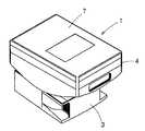
図1は、本実施形態に係る錠剤フィーダ1を円筒状にセットして使用する錠剤供給装置2を示す。
【0010】
錠剤フィーダ1は、図2に示すように、錠剤供給装置2に設けられるケース支持台3と、このケース支持台3に着脱自在な錠剤収容ケース4とから構成される。
【0011】
ケース支持台3の内部には、制御装置(図示せず)からの制御信号に基づいて駆動制御されるモータ(図示せず)が収容されている。
【0012】
錠剤収容ケース4は、図3に示すように、略箱状で、上面が蓋体7によって開閉可能となっている。錠剤収容ケース4の底壁上面は略円錐状に形成され、そこにはロータ8が配設されている。ロータ8の円錐下面には溝状のポケット部9が等角度で複数形成されている。ポケット部9は、収容した錠剤を1つだけ保持可能な幅及び深さを有する。前記ロータ8には、図示しないギアを介して前記ケース支持台3に設けたモータの動力が伝達されるようになっている。また、錠剤収容ケース4内は、対向する側壁間にサポート部11が形成されている。サポート部11は、上方に向かって突出する断面略円弧状で、ロータ8の上方空間を横切るように形成され、その上方に位置する錠剤を支持する。したがって、ロータ8には、サポート部11との間に位置する錠剤の重量のみが作用する。このため、前記ケース支持台3に設けたロータ8を、駆動力がそれ程大きなモータを使用しなくても、スムーズに回転させることができる。また、サポート部11は、前述のように、上方に向かって突出する断面略円弧状に形成されているため、その上面(滞留防止部)に錠剤が残留することはない。
【0013】
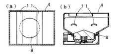
前記錠剤収容ケース4に形成したサポート部11は、図4〜図15に示すように構成することもできる。
【0014】
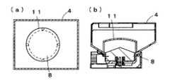
図4〜図8では、サポート部11が、前記実施形態と同様に、対向する側壁間に形成されている。この構成であれば、製作も簡単であり、所望の強度を得ることができる。図4〜図6ではサポート部11は2列に形成されている。図4では中央側に向かって下方に傾斜し、図5では中央側に向かって上方に傾斜し、図6では上方に突出する円弧状に形成されることにより滞留防止部を構成している。また、図7では山型、図8では一方に傾斜、図9では3本の棒状にそれぞれ形成されることにより滞留防止部を構成している。
【0015】
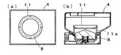
図10〜図14では、サポート部11が略円盤状に形成され、底面や側面から延設した支持部で支持されている。図10ではサポート部11はドーム状、図11では中心部に向かって下方に傾斜するドーナツ状、図12では星形、図13では図10の対向縁部を円弧状に切除した形状、図14では円錐部の外周にブラシ部が形成された形状にそれぞれ形成されることにより滞留防止部を構成している。図14のブラシ部を有するものでは、錠剤に無理な負荷がかかって損傷させる心配がない点で好ましい。
【0016】
図15は、サポート部11を一方の側壁から排出通路10の上方側のみに延設することにより、必要最小限の範囲に形成されている。
【0017】
なお、前記実施形態では、サポート部11を錠剤収容ケース4に固定するようにしたが、取り外し可能に構成してもよい。すなわち、ロータ8が回転して錠剤が移動しても、錠剤収容ケース4内でサポート部11が転倒したり、持ち上げられる等によりサポート部11の機能が損なわれなければ、その設置構造は制約を受けない。また、錠剤収容ケース4内に錠剤が大量に収容された場合であっても、ロータ8に錠剤の自重が直接作用することを防止できるのであれば、サポート部11の形状は、前記実施形態に制限されるものではない。さらに、本発明の滞留防止部には、前記実施形態の略円錐状、円弧状等に限らず、カプセル状、細長い形状や滑りの悪いカルシウム系の薬種である裸錠であっても、スムーズにロータ8に設けたポケット部9に移動させることができるようなもの等、種々の構成が含まれる。
【0018】
また、本発明に係るサポート部11は、例えば、特公昭63−50242号公報の第4図(b),(c)に示す構造の錠剤フィーダのように、大量の錠剤を収容可能な場合に特にその効果を発揮する。
【0019】
【発明の効果】
以上の説明から明らかなように、本発明によれば、錠剤収容ケース内にサポート部を設けるようにしたので、錠剤を大量に収容した場合であっても、ロータの回転が妨げられることはなく、錠剤をスムーズに払い出すことができる。
【図面の簡単な説明】
【図1】 本実施形態に係る錠剤フィーダが複数設けられる錠剤供給装置の概略斜視図である。
【図2】 図1に示す錠剤フィーダの斜視図である
【図3】 (a)は他の形態に係るサポート部を備えた錠剤収容ケースの平面断面図、(b)は立面断面図である。
【図4】 (a)は他の形態に係るサポート部を備えた錠剤収容ケースの平面断面図、(b)は立面断面図である。
【図5】 (a)は他の形態に係るサポート部を備えた錠剤収容ケースの平面断面図、(b)は立面断面図である。
【図6】 (a)は他の形態に係るサポート部を備えた錠剤収容ケースの平面断面図、(b)は立面断面図である。
【図7】 (a)は他の形態に係るサポート部を備えた錠剤収容ケースの平面断面図、(b)は立面断面図である。
【図8】 (a)は他の形態に係るサポート部を備えた錠剤収容ケースの平面断面図、(b)は立面断面図である。
【図9】 (a)は他の形態に係るサポート部を備えた錠剤収容ケースの平面断面図、(b)は立面断面図である。
【図10】 (a)は他の形態に係るサポート部を備えた錠剤収容ケースの平面断面図、(b)は立面断面図である。
【図11】 (a)は他の形態に係るサポート部を備えた錠剤収容ケースの平面断面図、(b)は立面断面図である。
【図12】 (a)は他の形態に係るサポート部を備えた錠剤収容ケースの平面断面図、(b)は立面断面図である。
【図13】 (a)は他の形態に係るサポート部を備えた錠剤収容ケースの平面断面図、(b)は立面断面図である。
【図14】 (a)は他の形態に係るサポート部を備えた錠剤収容ケースの平面断面図、(b)は立面断面図である。
【図15】 (a)は他の形態に係るサポート部を備えた錠剤収容ケースの平面断面図、(b)は立面断面図である。
【符号の説明】
1…錠剤フィーダ
3…ケース支持台
4…錠剤収容ケース
8…ロータ
9…ポケット部
11…サポート部[0001]
BACKGROUND OF THE INVENTION
The present invention relates to a tablet feeder.
[0002]
[Prior art]
2. Description of the Related Art Conventionally, there is a tablet feeder in which a tablet stored in the tablet storage case is dispensed by rotating a rotor provided in the tablet storage case. As such a tablet feeder, one having a different volume depending on the size and amount of the tablet is known (see Japanese Patent Publication No. 63-50242).
[0003]
[Problems to be solved by the invention]
However, in the tablet feeder, the weight of the tablet accommodated in the large-capacity one increases, and the rotor may not be able to rotate smoothly. For this reason, it is necessary to use an expensive motor having a large driving force for the motor for rotating the rotor.
[0004]
Accordingly, an object of the present invention is to provide a tablet feeder that can dispense a tablet by smoothly rotating a rotor even if it is a large-capacity type having a simple configuration.
[0005]
[Means for Solving the Problems]
As a means for solving the problems, the present inventiondrives amotor, rotates a rotor disposed in a tablet storage case, and stores the tablets stored in the tablet storage case in each pocket portion of the rotor. In the tablet feeder that is held and moved to the discharge portion and discharges the tablet from the discharge portion, a tablet that is located above the pocket portion of the rotor and acts on the pocket portion in the tablet storage case. Forming a support portion that prevents the weight from preventing rotation of the rotor, and the support portion includes a retention preventing portion that prevents the tablets from being stacked and smoothly holds the pocket portion; The stay prevention part is formed by forming a brush part on the outer periphery of the conical part.
[0008]
DETAILED DESCRIPTION OF THE INVENTION
Embodiments according to the present invention will be described below with reference to the accompanying drawings.
[0009]
FIG. 1 shows a
[0010]
As shown in FIG. 2, the
[0011]
A motor (not shown) that is driven and controlled based on a control signal from a control device (not shown) is accommodated inside the case support 3.
[0012]
As shown in FIG. 3, the
[0013]
The
[0014]
4-8, the
[0015]
10-14, the
[0016]
FIG. 15 is formed in the minimum necessary range by extending the
[0017]
In addition, in the said embodiment, although the
[0018]
Further, the
[0019]
【The invention's effect】
As is clear from the above description, according to the present invention, since the support portion is provided in the tablet storage case, the rotation of the rotor is not hindered even when a large amount of tablets are stored. , Tablets can be dispensed smoothly.
[Brief description of the drawings]
FIG. 1 is a schematic perspective view of a tablet supply device provided with a plurality of tablet feeders according to the present embodiment.
2 is a perspective view of the tablet feeder shown in FIG. 1. FIG. 3 (a) is a plan sectional view of a tablet storage case having a support portion according to another embodiment, and FIG. 2 (b) is an elevational sectional view. is there.
4A is a plan cross-sectional view of a tablet storage case provided with a support portion according to another embodiment, and FIG. 4B is an elevational cross-sectional view.
5A is a plan cross-sectional view of a tablet storage case provided with a support portion according to another embodiment, and FIG. 5B is an elevational cross-sectional view.
6A is a plan sectional view of a tablet storage case provided with a support portion according to another embodiment, and FIG. 6B is an elevation sectional view.
FIG. 7A is a plan sectional view of a tablet storage case provided with a support portion according to another embodiment, and FIG. 7B is an elevation sectional view.
FIG. 8A is a plan sectional view of a tablet storage case provided with a support portion according to another embodiment, and FIG. 8B is an elevation sectional view.
FIG. 9A is a plan sectional view of a tablet storage case provided with a support portion according to another embodiment, and FIG. 9B is an elevation sectional view.
10A is a plan cross-sectional view of a tablet storage case provided with a support portion according to another embodiment, and FIG. 10B is an elevational cross-sectional view.
11A is a plan sectional view of a tablet storage case provided with a support portion according to another embodiment, and FIG. 11B is an elevation sectional view.
12 (a) is a plan sectional view of a tablet storage case provided with a support portion according to another embodiment, and FIG. 12 (b) is an elevation sectional view.
FIG. 13A is a plan sectional view of a tablet storage case provided with a support portion according to another embodiment, and FIG. 13B is an elevation sectional view.
14A is a plan cross-sectional view of a tablet storage case provided with a support portion according to another embodiment, and FIG. 14B is an elevational cross-sectional view.
FIG. 15A is a plan sectional view of a tablet storage case provided with a support portion according to another embodiment, and FIG. 15B is an elevation sectional view.
[Explanation of symbols]
DESCRIPTION OF
Claims (1)
Translated fromJapanese前記錠剤収容ケース内に、前記ロータのポケット部の上方に位置し、該ポケット部に作用する錠剤の重量が前記ロータの回転を阻止することを防止するサポート部を形成し、 In the tablet housing case, a support portion is formed which is located above the pocket portion of the rotor and prevents the weight of the tablet acting on the pocket portion from preventing the rotor from rotating.
該サポート部は、錠剤の積層を防止し、かつ、ポケット部での保持をスムーズに行わせる滞留防止部を備え、 The support portion includes a retention preventing portion that prevents the tablets from being stacked and smoothly holds the pocket portion.
該滞留防止部は、円錐部の外周にブラシ部を形成してなることを特徴とする錠剤フィーダ。 The stagnation prevention part has a brush part formed on the outer periphery of a conical part.
Priority Applications (7)
| Application Number | Priority Date | Filing Date | Title |
|---|---|---|---|
| JP2001250335AJP3790688B2 (en) | 2001-08-21 | 2001-08-21 | Tablet feeder |
| US10/217,645US6736286B2 (en) | 2001-08-21 | 2002-08-14 | Tablet feeder |
| CA002398686ACA2398686A1 (en) | 2001-08-21 | 2002-08-16 | Tablet feeder |
| EP02018557AEP1285850A3 (en) | 2001-08-21 | 2002-08-17 | Tablet feeder |
| KR1020020048782AKR100894541B1 (en) | 2001-08-21 | 2002-08-19 | Tablet feeder |
| NO20023942ANO20023942L (en) | 2001-08-21 | 2002-08-20 | tablet Mater |
| CNB021420521ACN1244473C (en) | 2001-08-21 | 2002-08-21 | Lozenge feeding devices |
Applications Claiming Priority (1)
| Application Number | Priority Date | Filing Date | Title |
|---|---|---|---|
| JP2001250335AJP3790688B2 (en) | 2001-08-21 | 2001-08-21 | Tablet feeder |
Publications (3)
| Publication Number | Publication Date |
|---|---|
| JP2003063503A JP2003063503A (en) | 2003-03-05 |
| JP2003063503A5 JP2003063503A5 (en) | 2005-01-06 |
| JP3790688B2true JP3790688B2 (en) | 2006-06-28 |
Family
ID=19079175
Family Applications (1)
| Application Number | Title | Priority Date | Filing Date |
|---|---|---|---|
| JP2001250335AExpired - Fee RelatedJP3790688B2 (en) | 2001-08-21 | 2001-08-21 | Tablet feeder |
Country Status (7)
| Country | Link |
|---|---|
| US (1) | US6736286B2 (en) |
| EP (1) | EP1285850A3 (en) |
| JP (1) | JP3790688B2 (en) |
| KR (1) | KR100894541B1 (en) |
| CN (1) | CN1244473C (en) |
| CA (1) | CA2398686A1 (en) |
| NO (1) | NO20023942L (en) |
Families Citing this family (27)
| Publication number | Priority date | Publication date | Assignee | Title |
|---|---|---|---|---|
| DE60320401T2 (en)* | 2002-05-13 | 2009-05-07 | Pebble Bed Modular Reactor (Proprietary) Ltd. | METHOD FOR UNLOADING SPHERICAL ELEMENTS FROM A CONTAINER AND OUTPUT DEVICE |
| JP4717368B2 (en)* | 2004-03-31 | 2011-07-06 | 株式会社湯山製作所 | Drug feeder |
| KR100578035B1 (en) | 2004-06-23 | 2006-05-11 | 박재태 | Food or Drug Dispensers |
| US20060231566A1 (en)* | 2005-04-14 | 2006-10-19 | Abe Indig | Apparatus and method for dispensing products |
| US8636172B2 (en)* | 2006-01-05 | 2014-01-28 | Lawrence A. Dunn | Devices, systems and methods for point-of-use medication control |
| US7885725B2 (en)* | 2006-01-05 | 2011-02-08 | Dunn Lawrence A | Devices, systems and methods for point-of-use medication control |
| US20080093372A1 (en)* | 2006-10-23 | 2008-04-24 | Milton Monroe T | Method and apparatus for sorting, counting and packaging pharmaceutical drugs and other objects |
| KR100804034B1 (en)* | 2007-02-06 | 2008-02-18 | 하진희 | Purifying Debranching |
| US20080245810A1 (en)* | 2007-04-05 | 2008-10-09 | Parata Systems, Llc | Methods and apparatus for dispensing solid pharmaceutical articles |
| US7949427B2 (en) | 2007-05-18 | 2011-05-24 | Parata Systems, Llc | Methods and apparatus for dispensing solid articles |
| US7837061B2 (en)* | 2007-05-18 | 2010-11-23 | Parata Systems, Llc | Methods and apparatus for dispensing solid pharmaceutical articles |
| US7832591B2 (en)* | 2007-05-18 | 2010-11-16 | Parata Systems, Llc | Methods and apparatus for dispensing solid pharmaceutical articles |
| US7870973B2 (en)* | 2008-01-09 | 2011-01-18 | Parata Systems, Llc | Methods and apparatus for dispensing solid articles |
| US8827113B2 (en)* | 2008-05-30 | 2014-09-09 | Parata Systems, Llc | Methods and apparatus for dispensing solid articles |
| KR101027589B1 (en) | 2008-09-18 | 2011-04-06 | 가부시키가이샤 유야마 세이사쿠쇼 | Drug dispensing device |
| CN102341307B (en)* | 2009-03-05 | 2014-12-17 | 株式会社汤山制作所 | Powder removing device for tablet feeder |
| US8054086B2 (en)* | 2009-06-25 | 2011-11-08 | Parata Systems, Llc | Apparatus for dispensing and detecting solid pharmaceutical articles and related methods of operation |
| US9333541B2 (en) | 2010-03-01 | 2016-05-10 | Yuyama Mfg. Co., Ltd. | Powder removal device of medicine dispenser |
| US20140102859A1 (en) | 2012-10-12 | 2014-04-17 | Mckesson Automation Inc. | Apparatuses, systems, and methods for dispensing medications from a central pharmacy to a patient in a healthcare facility |
| US9150119B2 (en) | 2013-03-15 | 2015-10-06 | Aesynt Incorporated | Apparatuses, systems, and methods for anticipating and delivering medications from a central pharmacy to a patient using a track based transport system |
| NL2009865C2 (en)* | 2012-11-22 | 2014-05-27 | Vmi Holland Bv | Device for dispensing and packing solid substances. |
| JP6000195B2 (en)* | 2013-07-03 | 2016-09-28 | 株式会社トーショー | Tablet cassette |
| TWI724134B (en)* | 2016-03-25 | 2021-04-11 | 日商湯山製作所有限公司 | Rotor for tablet box and tablet box |
| NL2016663B1 (en)* | 2016-04-22 | 2017-11-16 | Vmi Holland Bv | Apparatus and method for dispensing solid substances. |
| EP3896016A4 (en)* | 2018-12-13 | 2022-08-31 | Yuyama Mfg. Co., Ltd. | TABLET CASSETTE ROTOR AND TABLET CASSETTE |
| JP6906778B2 (en)* | 2018-12-25 | 2021-07-21 | 株式会社トーショー | Tablet cassette |
| CN119844996A (en)* | 2025-03-20 | 2025-04-18 | 华益药业科技(安徽)有限公司 | Tablet pelletization drying device |
Family Cites Families (11)
| Publication number | Priority date | Publication date | Assignee | Title |
|---|---|---|---|---|
| US3738507A (en)* | 1971-09-13 | 1973-06-12 | Sunkist Growers Inc | Bin for accumulating spherical articles |
| DE2356054C2 (en)* | 1973-11-09 | 1985-11-21 | Schwäbische Hüttenwerke GmbH, 7080 Aalen | Relief device for silos for heavy or non-flowing bulk goods |
| SE422447B (en)* | 1980-07-21 | 1982-03-08 | Forsberg G L K | DEVICE FOR PREVENTION OF BRIDGE OR Vault formation in bulk containers |
| JPS6147302A (en) | 1984-07-31 | 1986-03-07 | 株式会社 東京商会 | Partial packer for tablet |
| DE3529779A1 (en)* | 1985-08-20 | 1987-03-05 | Moeller Hamburg Gmbh Co Kg | Apparatus for reexciting flow in bulk material silos |
| JPS6350242A (en) | 1986-08-20 | 1988-03-03 | Nec Corp | Supervisory system for public telephone set |
| JPH0447041Y2 (en)* | 1988-08-08 | 1992-11-06 | ||
| JPH1033636A (en)* | 1996-05-03 | 1998-02-10 | Yuyama Seisakusho:Kk | Medicine separately wrapping device, medicine bottle, and medicine testing method |
| JP2909433B2 (en)* | 1996-05-31 | 1999-06-23 | 株式会社湯山製作所 | Pill feeder |
| US6170230B1 (en)* | 1998-12-04 | 2001-01-09 | Automed Technologies, Inc. | Medication collecting system |
| JP4346173B2 (en)* | 1999-10-06 | 2009-10-21 | 株式会社湯山製作所 | Tablet feeder |
- 2001
- 2001-08-21JPJP2001250335Apatent/JP3790688B2/ennot_activeExpired - Fee Related
- 2002
- 2002-08-14USUS10/217,645patent/US6736286B2/ennot_activeExpired - Fee Related
- 2002-08-16CACA002398686Apatent/CA2398686A1/ennot_activeAbandoned
- 2002-08-17EPEP02018557Apatent/EP1285850A3/ennot_activeWithdrawn
- 2002-08-19KRKR1020020048782Apatent/KR100894541B1/ennot_activeExpired - Fee Related
- 2002-08-20NONO20023942Apatent/NO20023942L/ennot_activeApplication Discontinuation
- 2002-08-21CNCNB021420521Apatent/CN1244473C/ennot_activeExpired - Fee Related
Also Published As
| Publication number | Publication date |
|---|---|
| EP1285850A3 (en) | 2006-03-29 |
| KR100894541B1 (en) | 2009-04-24 |
| US6736286B2 (en) | 2004-05-18 |
| KR20030017336A (en) | 2003-03-03 |
| NO20023942D0 (en) | 2002-08-20 |
| CA2398686A1 (en) | 2003-02-21 |
| CN1406816A (en) | 2003-04-02 |
| EP1285850A2 (en) | 2003-02-26 |
| JP2003063503A (en) | 2003-03-05 |
| NO20023942L (en) | 2003-02-24 |
| CN1244473C (en) | 2006-03-08 |
| US20030038143A1 (en) | 2003-02-27 |
Similar Documents
| Publication | Publication Date | Title |
|---|---|---|
| JP3790688B2 (en) | Tablet feeder | |
| US4815483A (en) | Cosmetic package with stacked rotatable trays | |
| ES2264002T3 (en) | CAPSULES FEEDING DEVICE FOR A BEVERAGE EXPENDING MACHINE. | |
| US7404376B2 (en) | Feed dispenser unit | |
| JP2003063503A5 (en) | ||
| JP6382631B2 (en) | Packaging container, lid for packaging container and packaging container with lid | |
| JPH09323701A (en) | Tablet feeder | |
| ES2822097T3 (en) | Device for dispensing items from a stack of nested items, in particular tumbler lids | |
| JPH10324309A5 (en) | ||
| JPH0331269U (en) | ||
| JP2017504396A (en) | Earplug dispenser with reduced friction | |
| JP5048318B2 (en) | Micro tablet weighing device | |
| RU2001120866A (en) | Centrifugal mixer | |
| JP4312859B2 (en) | Drug cassette | |
| JP4144295B2 (en) | Tablet case | |
| JP2011234865A (en) | Tablet feeder | |
| JP4964517B2 (en) | Pill case | |
| KR200465030Y1 (en) | Keeping box for toilet cleaning brush | |
| JP6569911B2 (en) | Tablet cassette | |
| KR20060057906A (en) | Car Cup Holder | |
| CN209594993U (en) | A kind of rotating disc type key storage box | |
| CN214631577U (en) | Cooking equipment | |
| JPS591698Y2 (en) | Medicine bottle holding frame | |
| JP4190627B2 (en) | Article dispensing device | |
| JP2008176409A (en) | Circular plate body storage unit, and circular plate body handling unit |
Legal Events
| Date | Code | Title | Description |
|---|---|---|---|
| A977 | Report on retrieval | Free format text:JAPANESE INTERMEDIATE CODE: A971007 Effective date:20050823 | |
| A131 | Notification of reasons for refusal | Free format text:JAPANESE INTERMEDIATE CODE: A131 Effective date:20050830 | |
| A521 | Request for written amendment filed | Free format text:JAPANESE INTERMEDIATE CODE: A523 Effective date:20051031 | |
| A131 | Notification of reasons for refusal | Free format text:JAPANESE INTERMEDIATE CODE: A131 Effective date:20051220 | |
| A521 | Request for written amendment filed | Free format text:JAPANESE INTERMEDIATE CODE: A523 Effective date:20060120 | |
| TRDD | Decision of grant or rejection written | ||
| A01 | Written decision to grant a patent or to grant a registration (utility model) | Free format text:JAPANESE INTERMEDIATE CODE: A01 Effective date:20060307 | |
| A61 | First payment of annual fees (during grant procedure) | Free format text:JAPANESE INTERMEDIATE CODE: A61 Effective date:20060403 | |
| R150 | Certificate of patent or registration of utility model | Free format text:JAPANESE INTERMEDIATE CODE: R150 | |
| LAPS | Cancellation because of no payment of annual fees |