JP3787375B2 - camera - Google Patents
cameraDownload PDFInfo
- Publication number
- JP3787375B2 JP3787375B2JP19359795AJP19359795AJP3787375B2JP 3787375 B2JP3787375 B2JP 3787375B2JP 19359795 AJP19359795 AJP 19359795AJP 19359795 AJP19359795 AJP 19359795AJP 3787375 B2JP3787375 B2JP 3787375B2
- Authority
- JP
- Japan
- Prior art keywords
- printer
- camera
- unit
- image
- printing
- Prior art date
- Legal status (The legal status is an assumption and is not a legal conclusion. Google has not performed a legal analysis and makes no representation as to the accuracy of the status listed.)
- Expired - Fee Related
Links
Images


Landscapes
- Facsimiles In General (AREA)
- Facsimile Scanning Arrangements (AREA)
Description
Translated fromJapanese【0001】
【発明の属する技術分野】
本発明は所謂、複合カメラ装置に係り、具体的には銀塩写真フィルムを使用したスチルカメラと画象プリンタを一体的に構成したカメラに関するものである。
【0002】
【従来の技術】
写真撮影において、撮影した写真プリントをその場で見たいという要望があった。このような要請から従来、例えば次のような特許が知られている。即ち、米国特許第3,709,122号、第3,727,529号、第4,000,500号、第4,249,811号、及び第4,212,524号等に係る装置や米国特許第3,707,116号に係るフィルムカートリッジ等、所謂インスタントカメラ及びインスタントフィルムによって撮影後、短い時間でプリントを鑑賞し得るシステムが開示されている。
【0003】
ところが、上掲の従来装置において、次のような問題点があった。
1)撮影された瞬間の画像はすべてインスタントフィルム上に記録されるのみであり、銀塩フィルム等に代表されるような保存性に優れ、且つ高画質の記録媒体に残しておくことができない。特に複数枚プリントしたい場合、インスタントフィルム上に形成された原画像を別の複写装置によってコピーするしかなく、その原画の保存方法等、銀塩フィルム等の場合に比べて不便である。
2)インスタント写真ではまた、撮影コマ毎にすべての撮影シーンがその場でプリントアウトされる。ところが、必ずしもすべての撮影シーンをその場でプリントアウトする必要性がない場合がある。つまり、その場ではプリントアウトせずに、後でまとめてプリントアウトする等の場合に対応することができない。
【0004】
そこで、上記のようなインスタント写真における問題点を補う方法として、次のようなプリンタ付カメラが考えられている。即ち、固体撮像素子に撮像した画像情報を、銀塩フィルムに対して露光する場合等とほぼ等価なタイミングでメモリに記憶しておき、この記憶された画像情報を任意の時にプリントアウトし得るように構成したものである。
【0005】
かかるプリンタ付カメラにおいて、カラーの画像情報をプリントアウトするために用いられるプリンタとして、一般的にa)溶融型熱転写プリンタ、b)昇華型熱転写プリンタ、或いはc)インクジェット型プリンタ等が適している。このうち特にインクジェット型プリンタは、ランニングコスト、小型化、省電力、出力スピード等の点で優れており、携帯性を必要とするプリンタ付カメラとして極めて有望である。これらの一例として米国特許第4,074,324号、特開昭54−136325号公報等に記載された装置において、固体撮像素子等によって電気的に撮像した画像情報をプリントアウトするプリンタ付カメラが開示されている。
【0006】
【発明が解決しようとする課題】
しかしながら、上記従来例では、静止画を撮影するための装置に、記録紙等の記録媒体に対して画像情報を出力するプリンタを一体的に構成していた。このためカメラ及びプリンタ双方に対する操作性が複雑化せざるを得ないばかりか、装置の構成やコスト等の点で、使用者において意図した撮影及びそのプリント出力を簡単に行い得るという要望に充分な解決方法を与えるものではなかった。
【0007】
ここで、プリンタ装置による電力消費を考える。昇華型熱転写プリンタの場合にはインクシートの材料を記録用ヘッドの熱によって直接的に気化させて、この気化した材料を記録用紙へ転写する必要がある。一般に、記録すべきプリントの全幅と同一長さを有する記録ヘッドに対してほぼ同時にエネルギを投入すること等から、極めて大きな電力を消費とする。
【0008】
一方、溶融型熱転写プリンタの場合には、インクシートの材料を液化させて、この液化した材料を記録用紙へ転写すると共に、記録するプリントの幅に対して記録用紙の送り方向にある幅だけを記録する動作を繰り返すようにしたものが主流をしめている。そして一般に、昇華型熱転写プリンタに比べると消費する電力は少ない。また、インクジェット型プリンタにおいては、液体であるインクを記録ヘッドによって発泡させて、そのインクをノズルから噴射する。このインクジェット型プリンタも昇華型熱転写プリンタに比べると消費する電力は少ない。
【0009】
しかしながら、いずれのプリンタ付カメラの場合においても、連続して記録ヘッドにエネルギを投入して用紙へ記録するようにしているため、プリント動作中には電源電圧が安定していなければならない。また逆にプリント動作中に装置電源から、他の機能を作動させるための電力を供給すると、電圧の変動等によってその機能が実質的に作動し得ない場合がある。
【0010】
つまりこの種のプリンタ付撮影装置において、プリント動作中に撮影装置の撮影動作を許可すると、電源電圧の状態や撮影動作中に電源電圧の変動があった場合等に不都合が生じ得る。例えばシャッタ開放用マグネットの吸引力の変動によって不用意にシャッタが作動(開放又は閉鎖)したり、所定の開放制御時間だけマグネットを吸引・保持し得ない等のシャッタ動作不良のおそれがある。更にストロボ用コンデンサに対するチャージ不足、或いは電圧変化のために適正なフィルム給送制御を行うことができず、フィルムへの日付の写し込み不良になる等、このように性能不良が起こり得る。
【0011】
本発明はこれらの問題点を考慮してなされたものであり、その第1の目的は、プリント動作中に撮影装置が動作することによる撮影装置の動作不良をなくした複合カメラ装置を提供することにある。
また、本発明の第2の目的は、プリント動作中には撮影装置を覗いていてもプリント動作中であることがわかり、不用意に撮影動作をしてしまうことのない複合カメラ装置を提供することにある。
また、本発明の第3の目的は、プリント動作中には次のプリントの画像取り込み動作を行なわず、出力中のプリントを適正に保ち得る複合カメラ装置を提供することにある。
【0012】
更に、プリント動作中に撮影装置による撮影が可能な状態において、撮影時にプリント出力用の画像の取り込みを行ない、プリント動作に用いている画像情報を蓄えているメモリに新たな画像情報を書き込んでしまうと、特にメモリがプリント出力用の1枚分の容量しかなく、或いは複数枚分のメモリを使い切って空き容量が残っていない場合等には、正常な画像をプリントし得なくなってしまう場合がある。従って、本発明の第4の目的は、プリント動作中には次のプリントのための画像取り込み動作を行なわず、出力中のプリント画像を適正に保つ装置を提供することにある。
【0013】
【課題を解決するための手段】
本発明のカメラは、撮像を行うためのレリーズスイッチと、前記レリーズスイッチの操作に応じて画像信号を形成する撮像手段と、前記撮像手段の画像信号を一時記憶するためのメモリ部と、前記レリーズスイッチとは別に設けられプリント動作をスタートさせるためのプリンタスイッチと、前記プリンタスイッチの操作に応じて該メモリ部に記憶された前記画像信号を記録紙にプリントするためのプリンタ手段とを有し、前記プリンタ手段が、前記記録紙へ前記メモリ部に記憶された前記画像信号をプリントしている間、前記レリーズスイッチの操作を行った場合であってカメラの電源電圧が所定よりも低いことが測定された場合には、前記撮像手段からの画像信号を前記メモリ部に記憶する動作を禁止するように制御する制御手段を有することを特徴とする。
【0014】
また、本発明のカメラにおいて、前記プリンタ手段が、前記記録紙へ前記メモリ部に記憶された前記画像信号をプリントしている間、プリント動作中であることを表示するプリント表示手段を有することを特徴とする。
【0015】
また、本発明のカメラにおいて、前記制御手段は前記カメラの電源を入れるのにともなって、前記プリンタ手段のクリーニング動作を行なうモードを有することを特徴とする。
【0017】
【作用】
本発明によれば、映像情報を記録媒体に記録する撮影装置と、映像情報を記録用紙に出力するプリンタ装置とを一体的に構成した複合カメラ装置において、撮影装置のレリーズ動作をプリンタ装置の動作中に制御する制御手段を有する。制御手段はプリンタ装置がプリント動作を行なっているときには撮影装置のレリーズ動作を停止するものである。これによれば、プリント出力中にはレリーズ動作が行なわれないように動作する。
【0018】
また、本発明によれば、制御手段はプリンタ装置がプリント出力の動作を行なっているときに撮影装置のレリーズが行なわれた場合には、撮影装置の撮影動作は実行し、プリンタ装置への画像の取り込み動作は行なわないものである。これによれば、プリント出力中にはレリーズ動作は行なうが、プリント出力のための画像の取り込み動作は行なわないように動作する。
【0019】
また、本発明によれば、プリンタ装置がプリント出力の動作を行なっているときに撮影装置のレリーズが行なわれると、電源電圧の測定を行ない、所定の電圧以上の時には撮影装置のレリーズ動作を行なうものである。これによれば、電源電圧が所定以上あるときにはレリーズ動作を行なうように動作する。
【0020】
また、本発明によれば、制御手段はプリンタ装置がプリント出力の動作を行なっているときには少なくとも撮影装置のファインダ内の表示手段にプリント動作を行なっていることを示す表示を行なうものである。これによれば、プリント出力の動作中にはファインダ内でその旨が認識できるように動作する。
【0021】
【発明の実施の形態】
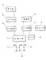
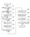
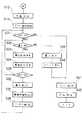
以下、図1乃至図6に基づき、本発明による複合カメラ装置の第1実施例について説明する。図1は本発明装置の主たる構成を表わしたブロック図であり、図2及び図3はこの装置における動作の流れを示すフローチャートである。
【0022】
本発明装置において、プリンタエンジン部にてインクジェット記録方式を採用し、またスチルカメラ部にて銀塩フィルムを用いた装置を採用している。これらを用いて動作の手順に従って説明する。
先ず、撮影者が装置の電源(メインスイッチ)を入力することにより(図2、ステップ1(S1))、制御手段1は該装置が前回使用後、電源がオフされてから3日以上(72時間以上)経過しているか否かを判断する(S2)。3日以上経過していると判断された場合には、制御手段1は、プリンタ部の制御を受け持つプリンタ制御部4に対して回復ポンピングの指示を出して、プリンタエンジン部6を駆動する(S3)。
【0023】
ここで、回復ポンピングは、後述するインクジェット記録方式の装置における記録動作をより有効に作用させるものであって、用紙に実際に記録を行なう前に予め記録ヘッドを吸引ポンプ等の手段によってクリーニングするものである。このクリーニングの目安として、本実施例においては3日間以上の未使用期間があった場合に、電源入力時にこれを行なうものとした。
【0024】
さて、撮影者が撮影に際してシャッタボタン12(図5参照)を第1ストロークまで押し込むと、図1のスイッチSW1の接点が導通してSW1信号7が発生する(S4)。この信号によって制御手段1はカメラ制御部2を介してカメラ部3を駆動して、露出制御値の決定や測距情報の決定、或いはストロボ発光の有無等の露出動作に必要な諸条件を決定する(S5)。また制御手段1はこれと同時に、プリンタ制御部4を介して撮像部5を駆動し、この撮像部5の固体撮像素子404(図6参照)に入力すべき光量を適正に保つように絞りユニット403(図6)を制御し、プリントアウトするための画像情報に対する撮像条件を決定する(S6)。
【0025】
次に、撮影者が実際に撮影を実行すべく、更にシャッタボタン12を押し込むと、図1のスイッチSW2の接点が導通してSW2信号8が発生する(S7)。この信号によって制御手段1はカメラ制御部2を介してカメラ部3を駆動し、焦点合わせのためのレンズ駆動やシャッタの速度制御、或いは絞りの開口量制御又は必要に応じてストロボ発光等の一連の露光動作を行なう(S8)。また制御手段1はこれと同時に、プリンタ制御部4を介して撮像部5を駆動し、固体撮像素子404に入力している画像情報がこのSW2信号8のタイミングでメモリ部10に取り込まれる(S9)。この後、撮影者がシャッタボタン12を離すと、フィルムの巻き上げがを行なわれる(S10)。
【0026】
撮影者においてプリントアウトを行わない場合、ここまでの一連の動作を終了する(S11)。一方、プリントアウトを望む場合には、装置上面に配設されたプリントボタン13を押すと、図1のPRスイッチの接点が導通し、プリント信号9が発生する。この信号によって制御手段1はプリンタ制御部4を介してプリンタエンジン部6を駆動してプリント動作を行なう。
【0027】
このプリント動作において、先ずプリンタ制御部4は記録ヘッド109a(図5参照)のホームポジション位置にて、プリント動作をより有効に作用させるべく予備吐出を行なう。これにより記録ヘッド109aの目詰まりを解消したり、或いは蒸発しているノズルの回復等を行なう(S12)。次にプリンタ制御部4はメモリ部10に蓄えられた画像情報をプリンタ出力用の画像処理を加えた上で、プリンタエンジン部6から出力する。この場合の画像処理において誤差拡散法等の画像処理法が有効である(S13)。
【0028】
プリント動作を実行している途中で、撮影者が再び撮影を行なおうとしてシャッタボタン12を押すと、再びSW1信号7が発生する(S14)。すると、制御手段1はカメラ制御部2に対してレリーズ禁止の信号を送出し、カメラ部3の駆動を停止させる(S16)。制御手段1はこれと同時に、カメラ制御部2を介して、カメラ部3のファインダ装置内部における視野枠306(図6)の至近位置に配設されたLED308を点灯させる。そしてプリズム307を介してLED308を視認できるようにし、これによりレリーズ動作を禁止している旨を撮影者に警告する(S15)。この警告は、通常プリント出力時の表示色を変えて、例えば赤色等で表示すると、よりいっそう効果的に行うことができる。
【0029】
このようにシャッタボタン12が押されてから、レリーズ動作の禁止及び警告表示を行っている間でも、シャッタボタン12が押されない場合と同様にプリント動作は続行すると共に、プリント動作中である旨を黄緑色等の色のLED308によって表示する(S17)。プリンタエンジン部6でプリントされたプリント用紙111a(図6)は、ロール状に巻かれたプリント用紙111と切り離される位置まで自動的に給紙される(S18)。このプリント用紙111aを切ることで、撮影者はスチルカメラ部に対するフィルムの露光と共に、ほぼ同一の画像をプリント出力としてその場で得ることができる。
【0030】
ここで、図4は、ファインダを覗いた際、該ファインダ内に表示されるLED308を示している。視野枠306内側のLED308aは、例えば黄緑色の発光色を有するLEDであって、プリント動作中であることを表示する。またLED308bは、赤色のLEDであって、レリーズ禁止のための警告表示であり、好適には点滅作動するように構成されている。
【0031】
次に、図5は、本発明に係るプリンタ付カメラにおいて好適に用いられるインクジェット記録装置部(IJRA;Ink-Jet Recording Apparatus )100の概念図である。図において、キャリッジ101は、ガイドバー102によってスライド自在に支持されると共に、螺旋溝104を有するリードスクリュ103とピン(図示せず)を介して係合する。リードスクリュ103は、駆動力伝達ギア105,1006,107を介して駆動モータ108と連結している。キャリッジ101は、駆動モータ108の正転及び逆転に連動して、矢印a,b方向に往復移動される。
【0032】
キャリッジ101にはインクジェットヘッドカートリッジ109が装着される。また、図において、110は紙押え板であり、キャリッジ101の移動方向に亘ってプリント用紙111をプラテン112に対して押圧する。113及び114はホームポジション検知手段としてのフォトカプラであり、キャリッジ101のレバー115を検出して、駆動モータ108の正・逆回転方向の切替等を行なわせる。116は記録ヘッド109aの前面をキャップするキャップ部材117を支持する部材、118はこのキャップ部材117内を吸引する吸引手段であり、キャップ部材117内の開口119を介して記録ヘッド109aの吸引回復を行なうようになっている。
【0033】
120はクリーニングブレード、121はこのクリーニングブレード120を前後方向に移動可能にする部材であり、これらの部材は、本体支持板122によって支持されている。クリーニングブレード120は、この形態のみならず、周知のクリーニングブレードを適用可能である。更に、123は記録ヘッド109aの吸引回復時の吸引を開始するためのレバーであり、キャリッジ101と係合し得るカム124の移動に伴って移動し、駆動モータ108からの駆動力がクラッチ切替等の伝達手段を介して移動制御される。
【0034】
これらのキャッピング、クリーニング及び吸引回復は、キャリッジ101がホームポジション側領域に位置したときに、リードスクリュ103の作用によってそれらの対応位置で所望の処理が行なえるように構成されている。従って、周知のタイミングで所望の動作を行なうようにすれば、本実施例においていずれも適用することができる。
【0035】
本発明によれば、特にインクジェット記録方式のうちでも、インク吐出を行わせるために利用するエネルギとして熱エネルギを発生する手段(例えば電気熱変換体やレーザ光等)を備え、熱エネルギによってインクの状態変化を生起させる方式の記録ヘッド、記録装置において優れた効果をもたらすものである。
【0036】
その代表的な構成及び原理等として、例えば、米国特許第4,723,129号明細書、或いは同第4,740796号明細書に開示されている基本的な原理を用いて行なうものが好ましい。この方式では特にオンデマンド型の場合には液体(インク)が保存されているシートや液路に対応して配置されている電気熱変換体に対して、記録すべき情報に対応し、該インクの沸点以上の急速な温度上昇を与える少なくとも一つの駆動信号を印加する。これにより電気熱変換体に熱エネルギを発生させ、記録ヘッドの熱作用面にて膜沸騰を起こさせて、結果的にはこの駆動信号に一対一対応する液体(インク)内の気泡を形成することができるため有効である。この気泡の成長・収縮により吐出用開口を介して液体(インク)を吐出させて、少なくとも一つの滴を形成する。
【0037】
また、かかる駆動信号をパルス形状とすることにより、即時適切に気泡の成長・収縮が行なわれるので、特に応答性に優れた液体(インク)を吐出することができるため、極めて好ましい。このパルス形状の駆動信号としては、米国特許第4,463,359号明細書、或いは同第4,345,262号明細書に記載されているものが適している。なお、上記記録ヘッドの熱作用面の温度上昇率に関する条件として、例えば米国特許第4,313124号明細書に記載されている条件を採用すると、更に優れた記録を行うことができる。
【0038】
記録ヘッドの構成としては、上述の各明細書に開示されているような吐出口、液路及び電気熱変換体の組み合わせ構成(直線状の液路又は直角状の液流路)の他に熱作用部が屈曲する領域に配置されている構成を開示する米国特許第4,558,333号明細書、或いは米国特許第4,459,600号明細書を用いた構成も本発明に含まれるものである。加えて、複数の電気熱変換体に対して、共通するスリットを電気熱変換体の吐出部とする構成を開示する特開昭59−123670号公報や熱エネルギの圧力波を吸収する開孔を吐出部に対応させる構成を開示する特開昭59−138461号公報に基づいた構成も本発明に有効である。
【0039】
更に、記録装置部で記録可能な最大の記録媒体の幅に対応した長さを有するフルラインタイプの記録ヘッドとしては、上述した明細書に開示されているような複数記録ヘッドの組み合わせによって、その長さを満たす構成や、一体的に形成された一個の記録ヘッドとしての構成のいずれでもよい。これらの構成を採用することにより本発明を一層有効に作用させることができる。加えて、装置本体に装着されることで、装置本体との電気的な接続や装置本体からのインクの供給が可能になる交換自在のチップタイプの記録ヘッド、或いは記録ヘッド自体に一体的に設けられたカートリッジタイプの記録ヘッドを用いた場合にも本発明は有効である。
【0040】
また、本発明の記録装置部の構成において、記録ヘッドに対する回復手段や予備的な補助手段等を付設することにより、より安定的に本発明の効果を得ることができる。これらの具体的構成例としては、記録ヘッドに対するキャッピング手段、クリーニング手段又は加圧もしくは吸引手段、また電気熱変換体或いはこれとは別の加熱素子又はこれらの組み合わせによる予備加熱手段、また記録とは別の吐出を行なう予備吐出モードを行なう等の構成を採用することができ、いずれの場合も安定した記録を行なうために極めて有効である。更に、記録装置部の記録モードとしては黒色等の主流色のみの記録モードだけでなく、記録ヘッドを一体的に構成し、或いは複数個の組み合わせによってでもよいが、異なる色の複色カラー又は、混色によるフルカラーの少なくとも一つを備えた装置であることが極めて有効になる。
【0041】
図6は、本実施例における複合カメラの中央断面図である。本発明に係る複合カメラ装置ではスチルカメラ部は、撮影光学系200とは別に被写体を視認するファインダ光学系300を有する所謂2眼レフ式カメラを、プリンタ部の上部に配置している。また、スチルカメラ部とプリンタ部の間にはプリンタの画像形成用の固体撮像素子を用いた第2の撮像光学系400が配置される。
【0042】
スチルカメラ部において、撮影光学系200のレンズユニット201及び202は、沈胴型の2段式の鏡筒203及び204にそれぞれ配置されている。205は撮影光束の制御と露光量の制御を兼用するシャッタユニットであり、鏡筒203内に配置されている。また、206は鏡筒204を回動させるためのヘリコイド部材であり、鏡筒204の凸状のカム部204aと係合している。このヘリコイド部材206は、図示しないヘリコイド駆動モータによって駆動される。
【0043】
撮影光学系200のレンズユニット201及び202とシャッタユニット205とを通った光束は、フィルム207上に結像する。フィルム207は、その平面性を保つように圧板バネ209によって付勢された圧板208により押圧され、これにより光学的に適正な位置関係を保持している。210はスチルカメラ部の背蓋であり、フィルム207の交換等の際に開閉される。
【0044】
ファインダ光学系300は、複数のレンズ301,302,303,304,305を有している。これらのうちレンズ302,303及び304は、撮影光学系200の画角調整(ズーム操作)に伴なって移動し得るように構成されており、撮影光学系200の画角とほぼ同一画角を確認することができる。306は視野枠である。307はプリズムであって、LED308の発光を撮影者において視認できるように光路変換する。
【0045】
画像形成用撮像光学系400において、プリンタ部に画像情報を送出するためのレンズユニット401及び402を有している。また、403は絞りユニットであり、固体撮像素子(CCD)404の露光量をフィードバック制御によって適正に保つように駆動される。これらのレンズユニット401,402は、スチルカメラ部の撮影光学系200の画角調整(ズーム操作)に伴って移動し得るように構成されており、撮影光学系200の画角とほぼ同一の画角で撮像することができる。プリンタ画像形成用の固体撮像素子404にて得られた画像信号は、信号処理基板405で処理される。
【0046】
次に、信号処理基板405によって信号処理が行なわれ、プリンタの制御信号が生成されると、その信号はプリンタ制御基板125へ送出される。そして更に、プリンタ部において、インクジェットヘッドカートリッジ109の位置制御信号等の情報と合わせたかたちで、印刷動作に必要な駆動モータ108等へ供給される。プリント動作は、図示しないプリント開始ボタンによって開始され、これによりロール状に巻かれたプリント用紙111からプラテン112を介して引き出されたプリント用紙111aに印刷される。なお、図6において、126は外装カバーの一部によって形成された紙カッタ部であり、印刷後のプリント用紙111aを手で切り離す際に用いられる。127はプリンタ部を駆動するための電源電池であり、スチルカメラ部への電力の供給も兼用している。
【0047】
図7乃至図10は、本発明の複合カメラ装置の第2実施例を示している。なお、第1実施例の場合と実質的に同一又は対応部材には同一の符号を用いて説明するものとする。
第2実施例に係る装置では、プリンタ部で印刷すべき画像情報を得るための撮像素子は、銀塩フィルムに結像する撮影光学系から分光された光路上に配置される。これにより銀塩フィルム上に記録される画像とほぼ同一画角の画像情報を得ることができるようにしたものである。この装置によれば、銀塩フィルム上に記録された画像が現像後にプリント処理されたものとほぼ同一画角のプリント出力を得られるため、銀塩写真プリントにかなり近いイメージのプリントを即座に入手することができる。
【0048】
図7は、第2実施例に係る装置における動作の流れを示すフローチャートである。なお、この装置動作においてプリント動作開始までの動作は、第1実施例の場合(図2、S1〜S13)と実質的に同一であり、ここではその説明を省略するものとする。先ず、プリント動作が開始した後に撮影者が再度シャッタボタン2035を押すと、SW1信号7が発生する(S21)。制御手段1は、第1実施例の場合(図2、S5)と同様に露出動作に必要な諸条件の決定を行なう(S22)。この場合には制御手段1は、プリンタ制御部4を介して撮像部5の駆動を禁止し、停止させておく。
【0049】
次に、撮影者がシャッタボタン2034を更に押し込むと、SW2信号8(図1参照)が発生する(S23)。この信号によって制御手段1は、カメラ制御部2を介してカメラ部3を駆動し、第1実施例の場合(図2、S8)と同様に一連の露光動作を行なう(S24)。ここで、制御手段1は、プリンタ制御部4を介して撮像部5からプリンタ出力用画像の取り込み動作を行なわないようにしている。つまりプリント動作が開始すると、プリンタ制御部4は、メモリ部10に記憶された画像情報に対してプリント出力用の画像処理を行なった上で、プリンタエンジン部6へ送出している最中であるため、メモリ部10のデータを書き換えるとプリント出力が不可能になるからである。従って、第2実施例によれば、プリント出力用画像の取り込みのためのメモリ部10が比較的小容量の場合に好適である。即ち、コスト低減を図った1枚分のメモリである場合や、複数枚のメモリにおいて撮影の度にメモリした後、メモリ容量が不足した場合等に特に有効となる。
【0050】
一連の露光動作の後、撮影者がシャッタボタン2034を離すと、フィルムの巻き上げを行なう(S25)。この間、プリント出力の動作は継続され(S26)、第1実施例の場合(図2、S18)と同様にプリント用紙111を切り離す位置まで自動的に給紙して一連の動作を終了する(S27)。この際、本発明装置のファインダである電子ビューファインダ2019内には、プリント動作の進行状況を示すバーグラフが表示される。このバーグラフ表示により、次のプリント出力のための画像取り込みがいつ行なえるかがわかるようになっている。
【0051】
ここで、図8は、本発明の第2実施例に係る複合カメラの機能を説明するための左側側面図である。図8において、2001は本発明装置の外装カバーであり、ネジ等によって締結された複数部分もしくは部品により構成される。2002は銀塩フィルムに像を取り込むためのレンズユニット、2003はレンズユニットを構成するレンズエレメントを保持するための鏡筒、2004は銀塩スチル撮影用の光彩絞り、2005は銀塩フィルムである。本実施例においてレンズユニット2002はズームレンズであり、自動もしくは手動のズーム操作に連動して、光軸上を移動可能な変倍レンズエレメント群、及び後述する自動焦点調節装置からの情報により駆動される合焦レンズエレメント群を有している。
【0052】
2006は銀塩フィルムの直前に配置されるシャッタ装置であり、シャッタ幕2006aやシャッタフレーム2006b等により構成される。2007は被写体からの画像をそれぞれ銀塩フィルム側とビデオ撮像素子に振り分けるための半透明薄膜ミラー、2007aは被写体側から入光される光軸、2007bは半透明薄膜ミラー2007を透過して銀塩フィルム2005側に到達する光軸、2007c,2007dは半透明薄膜ミラー2007によって反射された光軸である。2008a,2008bはそれぞれ光軸2007c上に設けられた被写体像の瞳合わせを行なうためのフィールドレンズ、2009は撮影光軸2007cを偏向するための反射ミラー、2010は光軸2007d上に設けられた縮小レンズユニットであり、内部にビデオ動画撮影用のビテオ絞りユニット2011を含んでいる。2012は光学ローパスフィルタ、2013は固体撮像素子である。2014は銀塩フィルム2005と等価な位置に結像された空中像であり、縮小レンズユニット2010を介して固体撮像素子2013上に再結像される。
【0053】
2015は半透明薄膜ミラー2007の後方にて撮影時、光軸2007bから退避可能に構成されたサブミラーであり、撮影光の一部を自動焦点検出装置2016へ導光する。本実施例における自動焦点検出装置2016は好適には、位相差ズレ検出方式ものが採用され、撮影レンズの異なる複数領域を通過した光束により生じる複数像を比較して、フィルム2005面上でのデフォーカス量及び方向を検知する。なお、固体撮像素子2013上にて常時、被写体像の得られているので、固体撮像素子2013からの高周波映像信号に基づいてボケ方式の自動焦点調節を行ってもよく、或いはまた本実施例のズレ方式との複合方式でもよい。
【0054】
2017は半透明薄膜ミラー2007を使用することによる光線漏れを防ぐために撮影時、光軸2007bから退避可能に構成された遮光板、2018は銀塩フィルム2005を装填し得るように開閉自在に設けられた背蓋ユニットである。本実施例では135タイプ(35mm)の銀塩フィルム2005を用いているが、これに限る必要はなく、ドロップインタイプのものや円盤タイプ等のフィルムであっても何ら差し支えない。
【0055】
2019は電子ビューファインダユニットであり、固体撮像素子2013からの映像信号をモニタするために、映像を小型液晶2020に表示し、反射ミラー2021及び接眼レンズ2022を介して観察し得るように構成されている。この電子ビューファインダーユニット2019は、回転軸2023を支軸として図8の矢印c方向に所定角度だけ回動可能となっている。
【0056】
また、図8に示した構成において、通常は銀塩スチル撮影用の光彩絞り2004は常に開放状態に維持され、後述する銀塩スチル撮影用のレリーズスイッチが押し込まれたときに所定の径まで絞りこまれる。一方、プリンタ出力用画像の取り込み時には縮小レンズユニット2010内のビデオ絞りユニット2011も露出制御され、必要に応じて撮像素子の蓄積時間や信号処理系のゲインを変えて適正露光を得るようになっている。
【0057】
更に、2024は本装置の下部に脱着可能に取り付けられる2次電池であり、本装置の全ての使用電力を供給する共通単一電源となっている。レンズユニット2003の前方には、ストロボ2025を組み込んだ開閉自在のバリヤ2026が配設される。また、2027はテレビやステレオ装置等の外部装置とのインターフェイスとしての外部端子である。
【0058】
図9は、第2実施例における上面図である。図において、2028は銀塩フィルム2005のパトローネ室、2029はフィルム2005を巻き取るためのスプールである。本実施例ではフィルム装填時に予め、フィルム2005の未露光の最終コマまでをスプール2029に巻き上げておき、撮影時に露光済みの駒をパトローネ室2028側へ順次巻き戻していくようにしたプリワインド方式を採用している。2030,2031はそれぞれ撮影レンズのズーム駆動用モータとフォーカス駆動用モータである。2032は撮影使用者の右手にて操作可能な位置に配置されたズームボタン、2033は電源スイッチを兼ねた主モード選択スイッチ、2034は銀塩フィルム2005の撮影時、又はプリントを開始する際に使用可能なスチル撮影用シャッタボタンである。
【0059】
上述の操作部材と反対側には、プログラム露出モード、開放絞りを多用するポートレートモード、シャッタ速度優先のスポーツモード或いは逆光モード等を選択使用可能なモード選択ダイヤル2035を配設する。測光については、各種モードに対応して、固体撮像素子2013の輝度信号レベルに応じてフィードバック制御することができる。本実施例ではプリンタ用撮像素子を電気的にエリア分割することにより測光素子として兼用しているが、別途専用の測光素子を配置してもよい。
【0060】
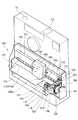
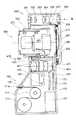
更に、2036はレンズユニット2002の右側方に配置されたプリンタエンジンユニットであり、本実施例では第1実施例のもの(図5参照)と実質的に同一構成のインクジェット記録装置100を使用している。なお、ここではインクジェット記録装置100の詳細な説明を省略するが、このインクジェット記録装置100にのみ限定されるものではない。プリンタエンジンユニット2036の上面には、プリントの画質調整や濃淡等を制御するためのコントロールパネル2037、或いは用紙の排出を指示するための排出ボタン2038が配置される。ここで、図10において、2039はプリンタエンジンユニット2036を覆うようにした外装カバーであり、プリンター用紙111の交換やインクジェットヘッドカートリッジ109の交換等に用いられる。
【0061】
次に、本発明の複合カメラ装置の第3実施例を説明する。図11は、第3実施例に係る装置における動作の流れを示すフローチャートである。なお、この装置動作においてプリント動作開始までの動作は、第1実施例等の場合(図2、S1〜S13)と実質的に同一であり、ここではその説明を省略するものとする。この第3実施例の装置は、電源電圧のモニタ機能を有したものである。この装置によれば所定の電源電圧があればプリント動作中にも次の撮影が行なえるというものである。
【0062】
プリント動作を実行している途中で、撮影者が再びシャッタボタン12を押すとSW1信号7が発生する(S31)。すると、制御手段1はプリント動作による実負荷がかかった状態で電源電池127の電圧を測定する。この状態でもし所定の電圧が得られない場合には、カメラ部3による撮影が不可能と判断され、ファインダ内のLED308を点灯させ、これにより撮影者へ警告すると共にレリーズ動作を禁止し、停止させる(S32,S39,S40)。一方、カメラ部3の撮影動作が可能である場合には、第1実施例の場合と同様にSW1信号7の入力からフィルム給送までの一連の動作(S4〜S10)を行なうように制御される(S33〜S38)。
【0063】
ここで、メモリ部10は、複数のプリンタ出力用画像の取り込みによる画像情報を記憶し得る容量を有している。プリンタ制御部4は、メモリ部10から読み出した画像情報を画像処理した上で、プリンタエンジン部6へ送出すると共に撮像部5から入力した次の画像情報をメモリ部10へ書き込んでいく。この間、プリンタ制御部4はプリント動作を続行する(S41)。
【0064】
仮に、電源電圧が所定の電圧基準値の近傍であって、両者を同時に動作させるには不十分な場合は一時的にプリント動作を停止してもよい。但し、この場合にはプリントの動作が中断したためにプリントにスジむらが生じたりしないように、プリントの区切りである1ライン分のプリントが終了した時点、或いは一色分のプリントが終了した時点等に中断させることが、より効果的である。そして、第1実施例の場合(図3、S18)と同様に、プリント用紙111aを切り離す位置まで自動的に給紙し、これにより一連の動作が終了する(S42)。
【0065】
【発明の効果】
以上説明したように、請求項1又は2に記載のカメラによれば、プリント動作を安定かつ確実に行なうことが可能なカメラを得ることができる。
請求項3に記載のカメラによれば、使用者がプリント動作中であることを把握し易いカメラを得ることができる。
請求項4又は5に記載のカメラによれば、煩雑な操作が不要なカメラを得ることができる。
請求項6及び7に記載のカメラによれば、銀塩カメラにおける撮影直後に即時プリントができると共に、プリント動作を安定に行なうことが可能になる。
【図面の簡単な説明】
【図1】本発明の複合カメラ装置の第1実施例における装置の主たる構成を表わしたブロック図である。
【図2】本発明の複合カメラ装置における動作の流れを示すフローチャートである。
【図3】本発明の複合カメラ装置における動作の流れを示すフローチャートである。
【図4】本発明の複合カメラ装置に係るファインダにおける表示例を示す図である。
【図5】本発明の複合カメラ装置に係るインクジェット記録装置部の概念図である。
【図6】本発明の複合カメラ装置の第1実施例における中央断面図である。
【図7】本発明の複合カメラ装置の第2実施例における動作の流れを示すフローチャートである。
【図8】本発明の複合カメラ装置の第2実施例における機能を説明するための左側側面図である。
【図9】本発明の複合カメラ装置の第2実施例における上面図である。
【図10】本発明の複合カメラ装置の第2実施例における斜視図である。
【図11】本発明の複合カメラ装置の第3実施例における動作の流れを示すフローチャートである。
【符号の説明】
1 制御手段
2 カメラ制御部
3 カメラ部
4 プリンタ制御部
5 撮像部
6 プリンタエンジン部
10 メモリ部
12 シャッタボタン
13 プリントボタン
100 インクジェット記録装置部
101 キャリッジ
102 ガイドバー
103 リードスクリュ
109 インクジェットヘッドカートリッジ
110 紙押え板
112 プラテン
115 レバー
117 キャップ部材
120 クリーニングブレード
122 本体支持板
124 カム
200 撮影光学系
201,202 レンズユニット
203,204 鏡筒
205 シャッタユニット
206 ヘリコイド部材
207 フィルム
208 圧板
300 ファインダ光学系
301,302,303,304,305 レンズ
307 プリズム
308 LED
400 画像形成用撮像光学系
401,402 レンズユニット
404 固体撮像素子
405 信号処理基板[0001]
BACKGROUND OF THE INVENTION
The present invention relates to a so-called composite camera device, and more specifically to a camera in which a still camera using a silver halide photographic film and an image printer are integrally formed.
[0002]
[Prior art]
In photography, there was a demand to view photographed photograph prints on the spot. Conventionally, for example, the following patents are known from such a request. That is, devices according to US Pat. Nos. 3,709,122, 3,727,529, 4,000,500, 4,249,811, and 4,212,524, etc. Japanese Patent No. 3,707,116 discloses a system capable of appreciating prints in a short time after photographing with a so-called instant camera and instant film such as a film cartridge.
[0003]
However, the above conventional apparatus has the following problems.
1) All images taken at the moment are only recorded on an instant film, and cannot be left on a high-quality recording medium having excellent storage stability such as a silver salt film. In particular, when it is desired to print a plurality of sheets, the original image formed on the instant film must be copied by another copying apparatus, which is inconvenient as compared with a silver salt film or the like, such as a method for storing the original image.
2) In the case of instant photos, all shooting scenes are printed on the spot for each shooting frame. However, there is a case where it is not always necessary to print out all shooting scenes on the spot. In other words, it is not possible to cope with a case where, for example, printing is not performed on the spot, but printing is performed collectively later.
[0004]
Therefore, the following camera with a printer has been considered as a method for making up for the problems in instant photography as described above. That is, the image information captured by the solid-state image sensor is stored in the memory at almost the same timing as when the silver salt film is exposed, and the stored image information can be printed out at any time. It is configured.
[0005]
In such a camera with a printer, generally, a) a melt type thermal transfer printer, b) a sublimation type thermal transfer printer, or c) an ink jet type printer are suitable as printers used for printing out color image information. Among these, the ink jet printer is particularly excellent in terms of running cost, miniaturization, power saving, output speed, and the like, and is extremely promising as a camera with a printer that requires portability. As an example of these, in a device described in U.S. Pat. No. 4,074,324, Japanese Patent Laid-Open No. 54-136325, etc., there is a camera with a printer that prints out image information electrically captured by a solid-state image sensor or the like. It is disclosed.
[0006]
[Problems to be solved by the invention]
However, in the above-described conventional example, a printer that outputs image information to a recording medium such as recording paper is integrally configured in a device for taking a still image. For this reason, the operability for both the camera and the printer must be complicated, and it is sufficient for the demand that the user can easily perform shooting and print output intended by the user in terms of the configuration and cost of the apparatus. It did not give a solution.
[0007]
Here, power consumption by the printer device is considered. In the case of a sublimation type thermal transfer printer, it is necessary to directly vaporize the material of the ink sheet by the heat of the recording head and transfer the vaporized material to the recording paper. In general, a very large amount of electric power is consumed because energy is input almost simultaneously to a recording head having the same length as the entire width of a print to be recorded.
[0008]
On the other hand, in the case of a melt-type thermal transfer printer, the material of the ink sheet is liquefied, the liquefied material is transferred to the recording paper, and only the width in the recording paper feeding direction is set with respect to the width of the print to be recorded. The one that repeats the recording operation is the mainstream. In general, less power is consumed than a sublimation thermal transfer printer. In an ink jet printer, ink that is liquid is foamed by a recording head, and the ink is ejected from a nozzle. This ink jet printer consumes less power than the sublimation thermal transfer printer.
[0009]
However, in any camera with a printer, energy is continuously input to the recording head so that recording is performed on the paper. Therefore, the power supply voltage must be stable during the printing operation. Conversely, if power for operating other functions is supplied from the apparatus power supply during the printing operation, the functions may not be substantially activated due to voltage fluctuations or the like.
[0010]
That is, in this type of photographing apparatus with a printer, if the photographing operation of the photographing apparatus is permitted during the printing operation, inconvenience may occur when the power supply voltage is changed or the power supply voltage fluctuates during the photographing operation. For example, there is a risk of shutter operation failure such as inadvertent operation of the shutter (opening or closing) due to fluctuations in the attractive force of the shutter opening magnet, or inability to attract and hold the magnet for a predetermined opening control time. Further, due to insufficient charge to the strobe capacitor or due to voltage change, proper film feeding control cannot be performed, resulting in poor printing of the date on the film.
[0011]
The present invention has been made in consideration of these problems, and a first object of the invention is to provide a composite camera device that eliminates malfunction of the photographing device due to operation of the photographing device during the printing operation. It is in.
A second object of the present invention is to provide a composite camera device that does not inadvertently perform a photographing operation because it is understood that the printing operation is in progress even if the photographing device is looked into during the printing operation. There is.
It is a third object of the present invention to provide a composite camera apparatus that can keep an output print properly without performing an image capture operation for the next print during the print operation.
[0012]
Further, in a state where photographing by the photographing device is possible during the printing operation, an image for print output is captured at the time of photographing, and new image information is written in the memory storing the image information used for the printing operation. In particular, when the memory has only the capacity for one sheet for print output, or when the memory for the plurality of sheets is used up and there is no free space, a normal image may not be printed. . Accordingly, it is a fourth object of the present invention to provide an apparatus for appropriately maintaining a print image being output without performing an image capture operation for the next print during the print operation.
[0013]
[Means for Solving the Problems]
The camera of the present invention includes a release switch for performing imaging, an imaging unit for forming an image signal in response to an operation of the release switch, a memory unit for temporarily storing the image signal of the imaging unit, and the release A printer switch provided separately from the switch for starting the printing operation, and printer means for printing the image signal stored in the memory unit on a recording sheet in accordance with the operation of the printer switch, It is measured that the power supply voltage of the camera is lower than a predetermined value when the printer means operates the release switch while printing the image signal stored in the memory unit on the recording paper. A control means for controlling to prohibit the operation of storing the image signal from the image pickup means in the memory unit. It is characterized in.
[0014]
Further, in the camera of the present invention, the printer means includes print display means for displaying that the printing operation is being performed while the image signal stored in the memory unit is printed on the recording paper. Features.
[0015]
In the camera of the present invention, the control means has a mode for performing a cleaning operation of the printer means as the camera is turned on.
[0017]
[Action]
According to the present invention, in a composite camera apparatus integrally configured with a photographing apparatus that records video information on a recording medium and a printer apparatus that outputs video information to a recording sheet, the release operation of the photographing apparatus is the operation of the printer apparatus. Control means for controlling inside. The control means stops the release operation of the photographing device when the printer device is performing the printing operation. According to this, the release operation is not performed during the print output.
[0018]
Further, according to the present invention, the control means executes the photographing operation of the photographing device when the photographing device is released while the printer device is performing the print output operation, and the image to the printer device is executed. Is not performed. According to this, the release operation is performed during the print output, but the image capturing operation for the print output is not performed.
[0019]
According to the present invention, the power supply voltage is measured when the photographing device is released while the printer device is performing the print output operation, and when the voltage is higher than a predetermined voltage, the photographing device is released. Is. According to this, when the power supply voltage is above a predetermined level, the release operation is performed.
[0020]
Further, according to the present invention, when the printer device is performing a print output operation, the control unit displays at least a display means in the finder of the photographing apparatus indicating that the print operation is being performed. According to this, during the print output operation, the operation is performed so that it can be recognized in the finder.
[0021]
DETAILED DESCRIPTION OF THE INVENTION
A first embodiment of the composite camera device according to the present invention will be described below with reference to FIGS. FIG. 1 is a block diagram showing the main configuration of the apparatus of the present invention, and FIGS. 2 and 3 are flowcharts showing the flow of operations in this apparatus.
[0022]
In the apparatus of the present invention, an ink jet recording system is employed in the printer engine section, and an apparatus using a silver salt film is employed in the still camera section. These will be described in accordance with the operation procedure.
First, when the photographer inputs the power supply (main switch) of the apparatus (FIG. 2, Step 1 (S1)), the control means 1 is more than 3 days (72) after the apparatus was turned off after the apparatus was last used. It is determined whether or not (over time) has elapsed (S2). If it is determined that three days or more have elapsed, the
[0023]
Here, the recovery pumping is to make the recording operation in the inkjet recording type apparatus to be described later more effective, and to clean the recording head in advance by means such as a suction pump before actually recording on the paper. It is. As a guideline for this cleaning, in this embodiment, when there is an unused period of 3 days or more, this is performed when the power is input.
[0024]
When the photographer pushes the shutter button 12 (see FIG. 5) to the first stroke during photographing, the contact of the switch SW1 in FIG. 1 is turned on and the
[0025]
Next, when the photographer further presses the
[0026]
When the photographer does not perform printout, the series of operations up to this point is terminated (S11). On the other hand, when a printout is desired, when the
[0027]
In this printing operation, first, the
[0028]
If the photographer presses the
[0029]
Even when the
[0030]
Here, FIG. 4 shows the
[0031]
Next, FIG. 5 is a conceptual diagram of an inkjet recording apparatus unit (IJRA; Ink-Jet Recording Apparatus) 100 that is preferably used in the camera with a printer according to the present invention. In the drawing, a
[0032]
An ink
[0033]
[0034]
These capping, cleaning, and suction recovery are configured such that when the
[0035]
According to the present invention, in the ink jet recording method, in particular, a means (for example, an electrothermal converter, a laser beam, etc.) for generating thermal energy as energy used for ink ejection is provided, and the ink is heated by the thermal energy. This provides an excellent effect in a recording head and a recording apparatus that cause a state change.
[0036]
As a typical configuration and principle thereof, for example, those performed using the basic principle disclosed in US Pat. No. 4,723,129 or US Pat. No. 4,740796 are preferable. In this method, particularly in the case of an on-demand type, the ink to be recorded corresponds to the information to be recorded on the electrothermal transducer disposed in correspondence with the sheet or liquid path in which the liquid (ink) is stored. Apply at least one drive signal that gives a rapid temperature rise above the boiling point of. As a result, heat energy is generated in the electrothermal transducer, and film boiling occurs on the heat acting surface of the recording head. As a result, bubbles in the liquid (ink) corresponding to this drive signal are formed. It is effective because it can. By the growth and contraction of the bubbles, liquid (ink) is ejected through the ejection opening to form at least one droplet.
[0037]
In addition, by making the drive signal into a pulse shape, bubbles are grown and contracted immediately and appropriately, so that it is possible to discharge a liquid (ink) having particularly excellent responsiveness, which is extremely preferable. As this pulse-shaped drive signal, those described in US Pat. No. 4,463,359 or US Pat. No. 4,345,262 are suitable. Incidentally, if the conditions described in, for example, U.S. Pat. No. 4,313124 are adopted as the conditions regarding the temperature rise rate of the heat acting surface of the recording head, further excellent recording can be performed.
[0038]
As the configuration of the recording head, in addition to the combination configuration (straight liquid path or right-angled liquid flow path) of the discharge port, the liquid path and the electrothermal transducer as disclosed in each of the above-mentioned specifications, A configuration using US Pat. No. 4,558,333, or US Pat. No. 4,459,600, which discloses a configuration in which the action portion is disposed in the bent region, is also included in the present invention. It is. In addition, for a plurality of electrothermal transducers, Japanese Patent Application Laid-Open No. Sho 59-123670 that discloses a configuration in which a common slit is used as a discharge portion of the electrothermal transducer or an aperture that absorbs pressure waves of thermal energy is provided. A configuration based on Japanese Patent Application Laid-Open No. 59-138461 which discloses a configuration corresponding to the discharge unit is also effective in the present invention.
[0039]
Furthermore, as a full-line type recording head having a length corresponding to the width of the maximum recording medium that can be recorded by the recording apparatus unit, a combination of a plurality of recording heads as disclosed in the above-described specification can be used. Either a configuration satisfying the length or a configuration as a single recording head formed integrally may be used. By adopting these configurations, the present invention can be more effectively operated. In addition, it is mounted on the main body of the device so that it can be electrically connected to the main body of the device and supplied with ink from the main body of the device. The present invention is also effective when a cartridge type recording head is used.
[0040]
Further, in the configuration of the recording apparatus section of the present invention, the effect of the present invention can be obtained more stably by providing recovery means for the recording head, preliminary auxiliary means, and the like. Specific examples of these configurations include capping means, cleaning means or pressurizing or suction means for the recording head, preheating means using an electrothermal converter, a heating element other than this, or a combination thereof, and recording. A configuration such as performing a preliminary discharge mode for performing another discharge can be employed, and in any case, it is extremely effective for performing stable recording. Further, as a recording mode of the recording apparatus unit, not only a recording mode of only a mainstream color such as black, but also a recording head may be configured integrally, or a plurality of combinations may be used. A device having at least one full color by color mixing is extremely effective.
[0041]
FIG. 6 is a central sectional view of the composite camera in the present embodiment. In the composite camera device according to the present invention, the still camera unit includes a so-called twin-lens reflex camera having a viewfinder
[0042]
In the still camera unit, the
[0043]
The light beams that have passed through the
[0044]
The viewfinder
[0045]
The image forming imaging
[0046]
Next, signal processing is performed by the
[0047]
7 to 10 show a second embodiment of the composite camera apparatus of the present invention. Note that the same reference numerals are used for substantially the same or corresponding members as in the first embodiment.
In the apparatus according to the second embodiment, an image sensor for obtaining image information to be printed by the printer unit is disposed on an optical path that is spectrally separated from a photographing optical system that forms an image on a silver salt film. As a result, image information having substantially the same angle of view as that of the image recorded on the silver salt film can be obtained. According to this device, an image recorded on a silver salt film can obtain a print output with almost the same angle of view as that printed after development. can do.
[0048]
FIG. 7 is a flowchart showing an operation flow in the apparatus according to the second embodiment. The operation up to the start of the printing operation in this apparatus operation is substantially the same as in the case of the first embodiment (FIG. 2, S1 to S13), and the description thereof is omitted here. First, when the photographer presses the
[0049]
Next, when the photographer further presses the
[0050]
When the photographer releases the
[0051]
FIG. 8 is a left side view for explaining functions of the composite camera according to the second embodiment of the present invention. In FIG. 8,
[0052]
A
[0053]
A sub-mirror 2015 is configured to be retractable from the
[0054]
A
[0055]
An
[0056]
In the configuration shown in FIG. 8, normally, the
[0057]
Further,
[0058]
FIG. 9 is a top view of the second embodiment. In the figure,
[0059]
A
[0060]
[0061]
Next, a description will be given of a third embodiment of the composite camera apparatus of the present invention. FIG. 11 is a flowchart showing an operation flow in the apparatus according to the third embodiment. The operation up to the start of the printing operation in this apparatus operation is substantially the same as in the case of the first embodiment (FIG. 2, S1 to S13), and the description thereof is omitted here. The apparatus of the third embodiment has a power supply voltage monitoring function. According to this apparatus, if there is a predetermined power supply voltage, the next photographing can be performed even during the printing operation.
[0062]
When the photographer presses the
[0063]
Here, the
[0064]
If the power supply voltage is in the vicinity of a predetermined voltage reference value and is insufficient to operate both simultaneously, the printing operation may be temporarily stopped. However, in this case, when printing for one line, which is a print delimiter, is completed, or when printing for one color is completed, etc., so that the printing operation is interrupted and streaks are not generated in the printing. It is more effective to interrupt. Then, as in the case of the first embodiment (FIG. 3, S18), the
[0065]
【The invention's effect】
As described above, according to the camera of the first or second aspect, a camera capable of performing a printing operation stably and reliably can be obtained.
According to the camera of the third aspect, it is possible to obtain a camera that allows the user to easily grasp that the printing operation is being performed.
According to the camera of
According to the camera described in
[Brief description of the drawings]
FIG. 1 is a block diagram showing a main configuration of an apparatus in a first embodiment of a composite camera apparatus of the present invention.
FIG. 2 is a flowchart showing a flow of operations in the composite camera apparatus of the present invention.
FIG. 3 is a flowchart showing a flow of operations in the composite camera device of the present invention.
FIG. 4 is a diagram showing a display example in a viewfinder according to the composite camera device of the present invention.
FIG. 5 is a conceptual diagram of an ink jet recording apparatus section according to the composite camera apparatus of the present invention.
FIG. 6 is a central sectional view of the composite camera device according to the first embodiment of the present invention.
FIG. 7 is a flowchart showing an operation flow in the second embodiment of the composite camera apparatus of the present invention.
FIG. 8 is a left side view for explaining functions in the second embodiment of the composite camera apparatus of the present invention;
FIG. 9 is a top view of a second embodiment of the composite camera device of the present invention.
FIG. 10 is a perspective view of a composite camera device according to a second embodiment of the present invention.
FIG. 11 is a flowchart showing an operation flow in the third embodiment of the composite camera apparatus of the present invention;
[Explanation of symbols]
1 Control means
2 Camera control unit
3 Camera section
4 Printer control unit
5 Imaging unit
6 Printer engine
10 Memory part
12 Shutter button
13 Print button
100 Inkjet recording device
101 Carriage
102 Guide bar
103 Lead screw
109 Inkjet head cartridge
110 Paper holding plate
112 platen
115 lever
117 Cap member
120 Cleaning blade
122 Body support plate
124 cams
200 Shooting optical system
201, 202 Lens unit
203, 204
205 Shutter unit
206 Helicoid member
207 films
208 pressure plate
300 Viewfinder optical system
301, 302, 303, 304, 305 Lens
307 prism
308 LED
400 Imaging optical system for image formation
401, 402 Lens unit
404 Solid-state image sensor
405 Signal processing board
Claims (3)
Translated fromJapanese前記レリーズスイッチの操作に応じて画像信号を形成する撮像手段と、
前記撮像手段の画像信号を一時記憶するためのメモリ部と、
前記レリーズスイッチとは別に設けられプリント動作をスタートさせるためのプリンタスイッチと、
前記プリンタスイッチの操作に応じて該メモリ部に記憶された前記画像信号を記録紙にプリントするためのプリンタ手段とを有し、
前記プリンタ手段が、前記記録紙へ前記メモリ部に記憶された前記画像信号をプリントしている間、前記レリーズスイッチの操作を行った場合であってカメラの電源電圧が所定よりも低いことが測定された場合には、前記撮像手段からの画像信号を前記メモリ部に記憶する動作を禁止するように制御する制御手段を有することを特徴とするカメラ。A release switch for imaging,
Imaging means for forming an image signal in response to an operation of the release switch;
A memory unit for temporarily storing an image signal of the imaging means;
A printer switch provided separately from the release switch for starting a printing operation;
Printer means for printing on the recording paper the image signal stored in the memory unit according to the operation of the printer switch,
It is measured that the power supply voltage of the camera is lower than a predetermined value when the printer means operates the release switch while printing the image signal stored in the memory unit on the recording paper. In this case, the camera has control means for controlling to prohibit the operation of storing the image signal from the imaging means in the memory unit.
前記プリンタ手段が、前記記録紙へ前記メモリ部に記憶された前記画像信号をプリントしている間、プリント動作中であることを表示するプリント表示手段を有することを特徴とするカメラ。The camera of claim 1,
A camera comprising: a print display means for displaying that a printing operation is being performed while the printer means is printing the image signal stored in the memory unit onto the recording paper.
前記制御手段は前記カメラの電源を入れるのにともなって、前記プリンタ手段のクリーニング動作を行なうモードを有することを特徴とするカメラ。The camera of claim 1,
2. The camera according to claim 1, wherein the control unit has a mode for performing a cleaning operation of the printer unit as the camera is turned on.
Priority Applications (1)
| Application Number | Priority Date | Filing Date | Title |
|---|---|---|---|
| JP19359795AJP3787375B2 (en) | 1995-07-28 | 1995-07-28 | camera |
Applications Claiming Priority (1)
| Application Number | Priority Date | Filing Date | Title |
|---|---|---|---|
| JP19359795AJP3787375B2 (en) | 1995-07-28 | 1995-07-28 | camera |
Publications (2)
| Publication Number | Publication Date |
|---|---|
| JPH0946563A JPH0946563A (en) | 1997-02-14 |
| JP3787375B2true JP3787375B2 (en) | 2006-06-21 |
Family
ID=16310611
Family Applications (1)
| Application Number | Title | Priority Date | Filing Date |
|---|---|---|---|
| JP19359795AExpired - Fee RelatedJP3787375B2 (en) | 1995-07-28 | 1995-07-28 | camera |
Country Status (1)
| Country | Link |
|---|---|
| JP (1) | JP3787375B2 (en) |
Families Citing this family (4)
| Publication number | Priority date | Publication date | Assignee | Title |
|---|---|---|---|---|
| JPH1056604A (en) | 1996-08-07 | 1998-02-24 | Olympus Optical Co Ltd | Electronic camera with built-in printer and medium to be recorded |
| AUPQ056099A0 (en) | 1999-05-25 | 1999-06-17 | Silverbrook Research Pty Ltd | A method and apparatus (pprint01) |
| JP4456206B2 (en)* | 1999-05-25 | 2010-04-28 | 富士フイルム株式会社 | Digital camera and image display method |
| JP3943287B2 (en)* | 1999-06-07 | 2007-07-11 | 富士フイルム株式会社 | Digital camera with printer and operation control method thereof |
- 1995
- 1995-07-28JPJP19359795Apatent/JP3787375B2/ennot_activeExpired - Fee Related
Also Published As
| Publication number | Publication date |
|---|---|
| JPH0946563A (en) | 1997-02-14 |
Similar Documents
| Publication | Publication Date | Title |
|---|---|---|
| US6552821B2 (en) | Printer-built-in image-sensing apparatus using strobe-light means and electric-consumption control method thereof | |
| JPH09116843A (en) | Imaging device with printer | |
| JP3715695B2 (en) | Compound camera | |
| JP2000275723A (en) | Camera | |
| JPH11164184A (en) | Photographing device with printer | |
| JP3787375B2 (en) | camera | |
| JP4040143B2 (en) | Printer and cartridge | |
| JPH1141549A (en) | Photographing device with printer and printer device | |
| JP4590112B2 (en) | Print system, digital camera and control method thereof | |
| JPH11177912A (en) | Imaging device with printer | |
| JP4307002B2 (en) | PRINT SYSTEM, IMAGING DEVICE, AND PRINT OUTPUT METHOD | |
| JPH0961934A (en) | Compound camera | |
| JPH0937121A (en) | Image recording system | |
| JPH1188747A (en) | Photographing device, printer device and photographing system | |
| JPH0934035A (en) | Image recording system | |
| JP4548970B2 (en) | Digital camera, printing system and control method thereof | |
| JPH11164185A (en) | Camera with printer | |
| JPH11275493A (en) | Photographing device with printer | |
| JPH0946562A (en) | Imaging device with printer | |
| JP2000118100A (en) | Device with printer and camera with printer | |
| JP2002199311A (en) | camera | |
| JPH11179935A (en) | Imaging device with printer | |
| JPH10322636A (en) | Camera with printer | |
| JP2001117162A (en) | Equipment provided with remote control device | |
| JPH11261932A (en) | Photographing device with printer |
Legal Events
| Date | Code | Title | Description |
|---|---|---|---|
| A61 | First payment of annual fees (during grant procedure) | Free format text:JAPANESE INTERMEDIATE CODE: A61 Effective date:20060327 | |
| R150 | Certificate of patent or registration of utility model | Free format text:JAPANESE INTERMEDIATE CODE: R150 | |
| FPAY | Renewal fee payment (event date is renewal date of database) | Free format text:PAYMENT UNTIL: 20100331 Year of fee payment:4 | |
| FPAY | Renewal fee payment (event date is renewal date of database) | Free format text:PAYMENT UNTIL: 20100331 Year of fee payment:4 | |
| FPAY | Renewal fee payment (event date is renewal date of database) | Free format text:PAYMENT UNTIL: 20110331 Year of fee payment:5 | |
| FPAY | Renewal fee payment (event date is renewal date of database) | Free format text:PAYMENT UNTIL: 20120331 Year of fee payment:6 | |
| FPAY | Renewal fee payment (event date is renewal date of database) | Free format text:PAYMENT UNTIL: 20130331 Year of fee payment:7 | |
| FPAY | Renewal fee payment (event date is renewal date of database) | Free format text:PAYMENT UNTIL: 20130331 Year of fee payment:7 | |
| FPAY | Renewal fee payment (event date is renewal date of database) | Free format text:PAYMENT UNTIL: 20140331 Year of fee payment:8 | |
| LAPS | Cancellation because of no payment of annual fees |