JP3786328B2 - Server and communication control method - Google Patents
Server and communication control methodDownload PDFInfo
- Publication number
- JP3786328B2 JP3786328B2JP21073298AJP21073298AJP3786328B2JP 3786328 B2JP3786328 B2JP 3786328B2JP 21073298 AJP21073298 AJP 21073298AJP 21073298 AJP21073298 AJP 21073298AJP 3786328 B2JP3786328 B2JP 3786328B2
- Authority
- JP
- Japan
- Prior art keywords
- server
- address
- client
- traffic
- representative address
- Prior art date
- Legal status (The legal status is an assumption and is not a legal conclusion. Google has not performed a legal analysis and makes no representation as to the accuracy of the status listed.)
- Expired - Lifetime
Links
Images


Classifications
- H—ELECTRICITY
- H04—ELECTRIC COMMUNICATION TECHNIQUE
- H04L—TRANSMISSION OF DIGITAL INFORMATION, e.g. TELEGRAPHIC COMMUNICATION
- H04L67/00—Network arrangements or protocols for supporting network services or applications
- H04L67/01—Protocols
- H04L67/10—Protocols in which an application is distributed across nodes in the network
- H04L67/1001—Protocols in which an application is distributed across nodes in the network for accessing one among a plurality of replicated servers
- H04L67/1004—Server selection for load balancing
- H04L67/1008—Server selection for load balancing based on parameters of servers, e.g. available memory or workload
- H—ELECTRICITY
- H04—ELECTRIC COMMUNICATION TECHNIQUE
- H04L—TRANSMISSION OF DIGITAL INFORMATION, e.g. TELEGRAPHIC COMMUNICATION
- H04L67/00—Network arrangements or protocols for supporting network services or applications
- H04L67/01—Protocols
- H04L67/10—Protocols in which an application is distributed across nodes in the network
- H04L67/1001—Protocols in which an application is distributed across nodes in the network for accessing one among a plurality of replicated servers
- H04L67/1004—Server selection for load balancing
- H04L67/101—Server selection for load balancing based on network conditions
- H—ELECTRICITY
- H04—ELECTRIC COMMUNICATION TECHNIQUE
- H04L—TRANSMISSION OF DIGITAL INFORMATION, e.g. TELEGRAPHIC COMMUNICATION
- H04L67/00—Network arrangements or protocols for supporting network services or applications
- H04L67/01—Protocols
- H04L67/10—Protocols in which an application is distributed across nodes in the network
- H04L67/1001—Protocols in which an application is distributed across nodes in the network for accessing one among a plurality of replicated servers
- H04L67/1004—Server selection for load balancing
- H04L67/1012—Server selection for load balancing based on compliance of requirements or conditions with available server resources
Landscapes
- Engineering & Computer Science (AREA)
- Computer Networks & Wireless Communication (AREA)
- Signal Processing (AREA)
- Computer Hardware Design (AREA)
- General Engineering & Computer Science (AREA)
- Data Exchanges In Wide-Area Networks (AREA)
- Small-Scale Networks (AREA)
- Computer And Data Communications (AREA)
Description
Translated fromJapanese【0001】
【発明の属する技術分野】
本発明は、複数のサーバコンピュータ(以下、単にサーバという)とクライアントコンピュータ(以下、単位クライアントという)が接続されたコンピュータネットワークのトラフィック制御技術に係り、特に、ネットワークの空き帯域の状況に基づいてクライアントが通信するサーバを動的に切り替えることにより、トラフィックのネットワーク全体での分散化を図るようにした通信システムに関する。
【0002】
【従来の技術】
従来、サーバとクライアントが接続されたコンピュータネットワークシステムにおいて、負荷の分散や障害対策のためにサーバを複数設けることが一般的に行われている。その場合、クライアントからのサービス要求が特定のサーバに集中し、クライアントへの応答性能が悪化することがある。そのため、従来から、様々なトラフィック制御やサーバの負荷分散に関する技術が提案されている。その例として、次のような文献が挙げられる。
【0003】
特開平9−319689号公報には、サーバに障害が起こると、ネームサーバより事前にクライアントに配布しておいた選択候補サーバリストから次のサーバを選択することが開示されている。これは、クライアントにサーバ選択のための特別な処理を持たせる必要があるため、その分コストが高くなる。また、これはサーバの負荷のみを問題としており、経由するネットワークの負荷については全く考慮されていない。さらに、予め代替のサーバを固定的に準備しておく必要があり、その分コストが高くなる。
【0004】
特開平7−154399号公報には、ネットワークにおける送受信可能なバッファサイズを制御するウィンドウによりネットワークへのデータ流入量を制御するフィードバック技術が開示されている。このフィードバック技術によると、輻輳は回避できるが、サーバとクライアントの物理的、論理的位置は固定であり、ネットワーク全体として資源を効率よく使っているとはいえない。
特開平7−319835号公報に記載されたものは、サーバの持つファイルのアクセス頻度に応じてファイルを分散させることによってサーバの負荷分散を図る技術に関するものである。これは、ネットワークの負荷分散については考慮していない。
特開平9−244979号公報に記載されたものは、サーバのアクセス頻度をサービス資源の再配置の契機としたものであり、ネットワークの負荷や輻輳状態を契機とすることについては全く考慮されていない。また、この場合、サービス資源の再配置によってクライアントがアクセス先(宛先アドレス)を意識して変更しなくてはならない。
【0005】
特開平10−023074号公報に記載されたものは、サーバに障害が発生した場合にサーバを切り替えるようにしたもので、ネットワークの負荷が高まったことを契機にサーバを切り替えることについては全く考慮されていない。また、サーバを切り替えるときにどのサーバを選ぶか、また切り替え先のサーバに必要なデータやアプリケーションが存在していない場合には切り替えられない。さらに、現用系のサーバがダウンすることを前提として予備系のサーバが稼動するため、現用系サーバの固有アドレスを予備系サーバが引き継いでしまうため、現用系サーバは、切り替え後には用いることができない。すなわち、サーバ切り替え後に固有アドレスでのサービスを行ったり、保守や管理のための通信ができなくなるという問題がある。
【0006】
【発明が解決しようとする課題】
上述したように、従来のトラフィック制御に関する技術は、サーバとクライアントの位置が固定されていて、その間のトラフィックをどのように迂回させるか、またはネットワーク内やエンドシステムの通信トラフィックの流量をどのように制御するかというものである。これは、予め、迂回路を用意する必要があるためコストの問題が生じたり、流量制限によるクライアントのレスポンス特性が悪化するという問題がある。
【0007】
また、従来のサーバ切り替え技術は、サーバの障害に対するバックアップを目的としたものであるため、バックアップサーバも事前の設定が必要な固定サーバであり、その準備のためのコストが高くなるという問題がある。さらに、ネットワークの負荷分散を検出してサーバを動的に切り替える手段もなかった。
従来のサーバの切り替え技術においては、クライアントに事前に設定を要するものが多く、インターネットのような全世界規模で流通しているWWW(WorldWide Web:ワールド・ワイド・ウェブ)サーバに対して、クライアントの設定やソフトウェアの変更なしに、ネットワークのトラフィックの状況によって、動的にサーバを切り替える確立した技術はなかった。
【0008】
トラフィックの集中する経路を迂回せずに、サーバを動的にネットワーク上で移動させることにより、ネットワークの使用率の低い部分を有効に使うようにすれば、ネットワーク全体としてトラフィックを平均化することができ、結果的に、クライアントの平均応答特性を改善することができる。例えば、インターネットで用いられるWWWなどのサーバとクライアント間の通信システムにおいて、中継ネットワークの混雑を解消し、ネットワーク全体でみて利用されていない回線やサーバを有効に使うことで、クライアントの得る通信サービスの速度や品質を向上することができると考えられる。
【0009】
しかし、トラフィックがネットワーク内で平均的に分散するように、クライアントの通信するサーバを適切な位置にある別のサーバに切り替えるための情報をどのように把握するかという課題がある。
また、クライアントに対するサービスを連続して提供するために、クライアントからみて動的にサーバを切り替え、さらに切り替えることをクライアントに意識させない、つまりクライアントには何の設定変更や制御機能を追加することなしに切り替えることが必要がある。
本発明の目的は、これらの課題を解決し、トラフィックの集中する経路を迂回することなしに、またクライアントには何の設定変更や制御機能の追加することなしに、トラフィック発生の源であるサーバを動的にネットワーク上で移動させることができ、ネットワークの使用率の低い部分を有効に使うことが可能な通信システムを提供することである。
【0010】
【課題を解決するための手段】
本発明は、上記目的を達成するために、具体的に次の如き手段を有する。
(1)ネットワークで接続された複数のサーバとクライアントに対してそれぞれを識別して通信するための固有のアドレスを持たせる。さらに、それらの複数のサーバのうちいずれか1つに固有アドレスとは異なる代表アドレスを割り当てる。クライアントはサーバからのサービスを受けるときは、この代表アドレスを指定する。サーバとクライアント間では、その通信経路上のトラフィックの状態を検出する手段により、状態が常に監視されており、通信速度やレスポンスタイムなどが一定の閾値を越えると、ネットワーク上の別のサーバに代表アドレスを動的に割り当て直す手段により、代表アドレスを引き継ぐ。サーバとクライアント間にルータなどの中継装置がある場合は、代表アドレスを引き継いだサーバが新しくダイナミック・ルーティングの手法を用いることにより、ネットワーク上の中継装置の経路情報が書き換えられ、代表アドレスを持つサーバが動的に移設されたかの如くになる。これにより、クライアントには一切設定変更やソフトウェアの変更なしに、通信相手のサーバが動的に切り替わるので、トラフィックの分散が行われ、クライアントが受けるサービスの通信速度やレスポンスタイムを改善することができる。
【0011】
(2)上記のサーバに代表アドレスを動的に割り当て直す手段の一つを以下に示す。まず、切り替え元サーバが切り替え先サーバ(バックアップサーバ)に対して、切り替え指示のパケットを送信することで代表アドレスの引き継ぎを行う。この切り替え指示パケットには、引き継ぐ代表アドレスを含んでいてもよいし、あるいは予めバックアップサーバに設定し無効化しておいた代表アドレスを有効化する指示を含んでいてもよい。切り替え元サーバは、予め設定しておいた複数のバックアップサーバの識別情報(固有アドレス)のリストと各種の属性情報と、上記の通信経路上のトラフィックの状態を検出する手段から得た情報に基づいて、その中で適切なサーバを選んで切り替指示パケットを出すことで、動的に代表アドレスの割当てをバックアップサーバに引き継がせることができる。
(3)上記の切り替え指示パケットを送信する装置は、上記のトラフィック検出手段を持ち、最適なトラフィック分散を行う判断機能を持った中継装置やネットワーク管理装置が行ってもよい。
【0012】
(4)上記のサーバの代表アドレスを動的に割り当て直す手段の一つとして、サーバとクライアントの経路上に中継装置がある場合、その中継装置で対応する方法がある。サーバの識別に使うアドレスとして、クライアントと中継装置の間の通信はサーバの代表アドレスを用い、中継装置とサーバの間の通信はサーバの固有アドレスを用いるように、パケットのアドレスを変換する機能を中継装置に持たせる。中継装置には、サーバの固有アドレスと代表アドレスの対応付けテーブル(アドレス変換テーブルと呼ぶ)を持ち、これを参照することでパケットの変換を行う。サーバの代表アドレスを動的に割り当て直すには、この変換テーブルの固有アドレスと代表アドレスの対応関係を書き換えることで実現する。ネットワークの構成によって、このパケットのアドレス変換機能をいくつか、または全ての中継装置に持たせる。サーバの動的切り替えは、このアドレス変換テーブルの動的書き換えによって実現できる。このアドレス変換テーブルの書き換えは、トラフィックの状態を検出する手段を持った中継装置やネットワーク管理システムから、書き換え指示情報を上記アドレス変換テーブルを持ったルータに送ることで実現する。
【0013】
(5)上記のサーバが代表アドレスを動的に割り当て直すときに、引き継ぐサーバ(バックアップサーバと呼ぶ)にクライアントに提供するデータを転送することで、バックアップサーバに必要な環境をそろえることができる。
(6)上記のサーバが、代表アドレスを動的に割り当て直すときに、引き継ぐサーバにアプリケーションプログラムを転送することで、バックアップサーバに必要な環境をそろえることができる。
(7)上記の各サーバとクライアント間のネットワークのトラフィックの状況を検出する手段として、レスポンスタイム測定用の折り返しパケットを使う方法がある。サーバは常時、クライアントの一部または全体に対してこのレスポンスタイム測定を一定間隔で実施する。バックアップ候補となるサーバは、これらのクライアントに対して常にレスポンスタイムを測定しておくか、現用サーバからの指示によって特定クライアントまでのレスポンスタイム測定を必要な時に実施する。
【0014】
(8)上記の各サーバとクライアント間のネットワークのトラフィックの状況を検出する別の手段として、各経路上にトラフィック計測手段を置くことにより検出する方法がある。サーバとクライアント間の経路上にある中継装置に、全てのトラフィックを監視し、統計をとる機能を持たせることで、サーバとクライアントとの間の総トラフィック量、その他の通信トラフィック量、空き帯域の量などを測定し、その情報を上記の現用サーバに渡し、サーバ切り替え判断の情報とする。
(9)上記の各サーバとクライアント間のネットワークのトラフィックの状況を検出するさらに別の手段として、通信パケットがネットワーク上で輻輳によって廃棄されたことにより発せられるメッセージを用いる方法がある。中継装置は、輻輳により送信不能、もしくは受信不能な量のトラフィックが発生すると、パケットの流量制限を行ったり、廃棄を行い送信元にメッセージを送信する。これらのメッセージの内容と発生数などの情報をもとに、通信状態の劣化を判断する。
【0015】
【発明の実施の形態】
(1)<実施形態1>
以下、本発明の通信システムにおいて、クライアントに最も通信速度の速いサーバからサービスを提供するようサーバの切り替えを行なう実施例を説明する。
図1は、本実施例の簡単な構成を示す図である。
同図において、101は現用サーバ、102はバックアップ用サーバ、103は現用サーバ101のあるネットワーク、104はバックアップサーバ102のあるネットワークである。105は最初に現用サーバ101と通信しているクライアント、106はクライアント105のあるネットワーク、107はネットワーク103とネットワーク106を接続する回線、108はネットワーク104とネットワーク106を接続する回線である。
【0016】
図1に示すように、本発明による通信システムでは、現用サーバ101とバックアップサーバ102の存在するネットワークは異なり、その経路も異なる。また、回線107は回線108より通信帯域が広いものとする。109は回線107に接続されたネットワーク103のルータ、110は回線108に接続されたネットワーク104のルータ、111は回線107と108に接続されたネットワーク106のルータである。112は、ネットワーク103,104および106を管理するネットワーク管理装置である。
【0017】
図1において、現用サーバ101の固有アドレスとしてA1、バックアップ用サーバ102の固有アドレスとしてA2が設定され、現用サーバ101にはさらに代表アドレスとしてV1が設定されているものとする。
【0018】
図2は、本発明におけるサーバの一構成例である。
同図において、201はこのサーバの切り替え機能とサーバ機能を実行する制御部、202はサーバとクライアントとの間のトラフィックの状態を監視するトラフィック監視部、203はトラフィック監視部202で得たトラフィック情報と後述するメモリ207内にあるバックアップサーバ情報210に基づいてバックアップサーバをどれにするかを判断して選択する代替サーバ選択部、204は代替サーバ選択部203からの指示を受けて、バックアップサーバに対して代表アドレスを引き継ぐことを指示し、自己の持つ代表アドレスを無効化する処理を行うサーバ切り替え処理部、205はサーバのサービス機能を実行するアプリケーションプログラム処理部、206はサーバが外部と通信するための入出力部である。
【0019】
また、207は各種制御情報を保持する高速のメモリ、208はこのサーバに割当てられた固有アドレスのメモリ内の保持部、209は、複数のサーバのうち、このサーバだけに割当てられた代表アドレスのメモリ内の保持部、210はバックアップサーバに関する各種情報であるバックアップサーバ情報のメモリ内の保持部、211はアプリケーションプログラムに関わる情報やトラフィック情報などのデータを保持する外部記憶装置、212は、上述した制御部201,メモリ207,入出力部206,外部記憶装置211を相互に接続する内部バスである。
図2に示したサーバの構成例では、サーバの切り替えに必要な要素を中心に記述しているので、サーバがクライアントに提供する各種機能要素については、省略している。
【0020】
図3は、本発明におけるルータの一構成例である。
同図において、301は本発明によるルータの機能を実行する制御部、302はパケットの経路選択および転送処理を行うルーティング処理部、303は各種情報を保持するメモリ、304はネットワークの経路情報をメモリ内に貯えたルーティングテーブル、305〜308は、このルータのパケット送受信を行う入出力部、309は制御部301とメモリ303および各入出力部305〜308を相互に接続する内部バスである。
図3に示した構成例では、サーバの切り替えに必要な要素を中心に記述しているので、ルータ本来の機能であるルーティング処理機構の詳細は省略してある。
【0021】
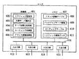
図4は、本発明におけるルータの別の構成例である。
同図において、401は本発明によるルータの機能を実行する制御部、402はサーバとクライアント間でのトラフィックの状況を監視するトラフィック監視部、403はトラフィック監視部402から得た情報と後述するメモリ407内にあるバックアップサーバ情報409に基づいてバックアップサーバをどれにするかを判断して選択する代替サーバ選択部、404は代替サーバ選択部からの指示により、サーバ切り替えを関連する各サーバに指示するサーバ切り替え処理部、405はパケットの経路選択および転送処理を行うルーティング処理部、406はサーバの固有アドレスと代表アドレスの変換処理を行うアドレス変換処理部である。
【0022】
また、407は各種情報を高速に記憶できるメモリ、408はサーバの固有アドレスと代表アドレスとの対応関係を記述したアドレス変換テーブル、409はバックアップサーバに関する各種情報を保持するバックアップサーバ情報のメモリ内の保持部、410はネットワークの経路情報を持つルーティングテーブル、411はサーバとクライアント間のトラフィック統計データのメモリ内の保持部、412〜415は、このルータのパケット送受信を行う入出力部、416は制御部401とメモリ407および各入出力部412〜415を相互に接続する内部バスである。
図4の構成例では、サーバの切り替えに必要な要素を中心に記述しているので、ルータ本来の機能であるルーティング処理機構の詳細は省略してある。
【0023】
図5は、本発明で用いられる一般的なクライアントの構成例である。本発明では、クライアントに対して何ら変更を加えるものではないため、この図においては特に発明に関わる要素はないが、以降の説明上必要なので、簡単に記述する。同図において、501はクライアントの動作を制御する機能を持つ制御部、502はクライアント上で動作するクライアント用アプリケーションプログラム処理部、503はクライアントが外部と通信するときにパケットを送受信する入出力部、504はクライアントの動作に必要な情報を高速に記憶するメモリ、505はこのクライアントに割当てられた固有アドレスのメモリ内の保持部、506はクライアントが通信するサーバの代表アドレスのメモリ内の保持部、507はメモリ504に比べて各種情報を、より長期的,より大量に保存するための大容量の外部記憶装置、508は、制御部501,メモリ504,入出力部503および外部記憶装置507を相互に接続する内部バスである。
本クライアントの構成例では、サーバの切り替え動作に関連する部分のみを記述しており、その他の処理に関わる部分については記述を省略してある。
【0024】
図9は、ルータのアドレス変換テーブル408(図4参照)の内容例である。同図において、901はサーバの固有アドレスフィールドであり、902は各サーバが代表アドレスの割当てを持っているかどうかを示すとともに、もし代表アドレスの割当てを持っている場合にはそのアドレス値を示す代表アドレスフィールドである。
【0025】
次に、本実施例の動作をフローチャートを用いて詳細に説明する。
図7は現用のサーバの動作を示すフローチャートであり、図8はバックアップサーバの動作を示すフローチャートである。
図1において説明したように、現用サーバ101,バックアップサーバ102およびクライアント105は、それぞれを識別して通信するための固有のアドレスA1,A2,およびA3を持っている。さらに、サーバ101は、その固有アドレスとは異なる代表アドレスV1を割り当ててある。クライアント105は、サーバからのサービスを受けるときは、この代表アドレスV1を指定して通信を行う。
【0026】
図1の通信システムにおいて、クライアント105は現用サーバ101と通信しているものとする。このとき、現用サーバ101が複数のクライアントからアクセスを受けたり、その他のトラフィックで回線107の空き帯域が少なくなっているものとする。
現用サーバ101は、定期的にクライアント105に対してレスポンスタイム測定のための折り返しパケットをトラフィック監視部202より送信する(トラフィック情報収集:ステップ701)。TCP/IP(Transmission ControlProtocol/Internet Protocol)のICMP(Internet Control MessageProtocol)エコープロトコルなどがその折り返しパケットの典型例である。また、現用サーバ101がクライアント105に対して、どれだけの量のトラフィックを発生させているかも統計を取る。これにより、現用サーバ101は、回線上のトラフィックの状態を常に把握することができる。また、バックアップ用サーバ102も同様の手法でクライアント105に対して定期的にレスポンスタイムを測定している。
【0027】
現用サーバ101では、クライアント105に対するレスポンスタイム測定結果が予め決めておいた閾値を一定回数超えると(ステップ702:Y)、代替サーバ選択部203に通知し、ここで代替サーバの選択処理を行う(ステップ703)。なお、測定結果が閾値を一定回数超えたことを契機にサーバの交代要否を判断するようにしたのは、レスポンスタイムが瞬間的に悪化して閾値を超えることがあっても、超える回数が少ない場合は平均的にならせばトラフィックの負荷に問題がないことがあるためである。
【0028】
現用サーバ101の代替サーバ選択部203は、バックアップサーバ情報210と上記のレスポンスタイム測定値に基づいて、クライアント105にサービスを提供できる別のサーバで、クライアント105とその別のサーバ間でトラフィックが低く、現用サーバ101のトラフィックを処理できるかどうかを判断する(ステップ703)。バックアップサーバ情報201には、事前に設定可能な各種情報が含まれている。例えば、各サーバごとの、サーバの固有アドレス、サーバのOS(Operating System:オペレーティングシステム)、持っているアプリケーションプログラム、ネットワークインタフェース、クライアントからそのサーバまでの回線の総帯域幅、その回線の料金、サーバマシンの性能、サーバの所有者などである。
【0029】
代替サーバ選択部203では、代替サーバ候補102からクライアント105に対してどのくらいのレスポンスタイムを保証できるかを問い合わせる。代替サーバ候補102は、このクライアントに対して常にレスポンスタイムを折り返しパケットで測定しておくか、現用サーバ101からの問い合せによって特定クライアントまでのレスポンスタイム測定を実施するか、もしくは事前の知識としてバックアップ用サーバとして十分なトラフィック処理能力があることを前提に性能を測定しないかいずれかによって、保証できるレスポンスタイムを現用サーバ101に連絡する。
【0030】
これらの情報を総合的に判断し、現用サーバ101は、サーバの切り替え先であるバックアップ用サーバ102を決定し、サーバ切り替え処理部204に対して、切り替え処理実行を依頼する。
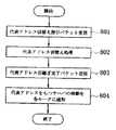
サーバ切り替え処理部204は、代替サーバの固有アドレスをバックアップサーバ情報210から得て、代表アドレスV1を引き継ぐ指示パケットを送信する(ステップ705)。
【0031】
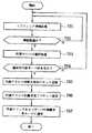
バックアップ用サーバ102では、現用サーバ101から送信された上記パケットにより代表アドレスV1を得て(ステップ801)、この代表アドレスV1での通信も可能にするよう動的に設定の変更を行う(ステップ802)。バックアップ用サーバ102では、代表アドレスV1の引き継ぎが完了すると現用サーバ101に対して完了通知を送信する(ステップ803)。
【0032】
現用サーバ101ではこれを受信し(ステップ706)、代表アドレスV1による通信を終了する。また、現用サーバ101では、自己のアドレスとして使っていた代表アドレスV1が消滅したことをダイナミックルーティングプロトコルにより、ルータ109に伝え、ルータ109では代表アドレスV1に対する経路が消滅したことをルータ111およびルータ110に伝える(ステップ707)。一方、バックアップ用サーバ102では、上記の現用サーバ101の代表アドレスV1消滅処理、経路消滅処理を行うのに十分な時間が経過したのち、自己のアドレスとして代表アドレスV1をダイナミックルーティングプロトコルにより、ルータ110に伝え、さらにルータ110はその経路情報をルータ111および109に伝える(ステップ804)。以上により、現用サーバがサーバ101からサーバ102に切り替えられる。このようにして、現用サーバをサーバ101からサーバ102への切り替えは、クライアントの設定変更なしに動的に実現することができ、またトラフィックが分散されるので、クライアントが受けるサービスの通信速度やレスポンスタイムを改善することができる。
【0033】
サーバの切り替えを行うときのレスポンスタイム測定は、1つまたはいくつかの代表クライアントに対して行うことも、全てのクライアントに対して行うことでもよい。しかし、後者の場合、クライアントの数が多いと、測定負荷がサーバと回線の両方を圧迫するため、現実的でない場合もある。
【0034】
次に、上記の各サーバとクライアント間のネットワークのトラフィックの状況を検出するさらに別の手段として、通信パケットがネットワーク上で輻輳によって廃棄されたことにより発せられるメッセージを用いる方法について以下に説明する。
一般に、ネットワークの輻輳が起こり、送信可能、もしくは受信可能な量のトラフィックが発生すると、中継装置がパケットの流量制限を行ったり、廃棄を行ったりするシステムがある。例えば、TCP/IPのICMPのソースクエンチと呼ばれる送信元に対するパケット流量制限、TCPのウィンドウサイズの制限、ICMPエラーメッセージでのパケット廃棄通知などがある。これらの通知情報は、ネットワークの負荷が高まった場合や輻輳が発生した場合に中継装置や相手システムから送信される。これらの情報を契機に、通信状態の劣化を判断し、これをもとに、バックアップ用サーバを新たな現用のサーバに切り替えることができる。ただし、この切り替えは、事前に定義しておいてもよいし、上記のようにバックアップ用サーバとクライアント間のトラフィックを測定して決めてもよい。
【0035】
上記の現用サーバの切り替えをするかどうかの判断には、上記に示した情報以外にも幾つかの情報が必要な場合がある。
一つ目は、各サーバからクライアントまでの空き帯域情報と現用サーバがクライアントに対して処理する単位時間当たりの総トラフィック量である。これは、サーバを切り替えることで、トラフィックがバックアップ用サーバに向けられ、事前に測定したレスポンスタイムよりかなり劣る値となり、切り替え前のほうが優る可能性があるため、切り替後のトラフィックを事前に計算する必要があるためである。
【0036】
2つ目は、クライアントの平均レスポンスタイムと各クライアントに対するレスポンスタイムの分散、最悪のレスポンスタイムなどである。いくら切り替えにより、各クライアントに対する平均レスポンスタイムが改善されるとしても、一部に極端に劣るレスポンスタイムのクライアントが発生する場合は切り替えないほうがよい場合もある。
その他、切り替えの判断にはネットワークの料金、切り替先のサーバの持ち主、切り替先のサーバの性能など各種属性情報を必要とする場合もある。
【0037】
上記の動作例で示したバックアップサーバへの代表アドレスの引き継ぎの方法以外に、予めサーバ切り替えに備えて代表アドレスV1を格納しておき、通常はその代表アドレスを無効化しておき、現用サーバからサーバ代替の切り替え指示パケットを受信したときに、その代表アドレスV1を有効化する方法もある。
サーバ101は、サーバの代表アドレスV1をサーバ102に引き継ぐ際、クライアントへのサービスを提供するために必要なデータを送信することもできる。これは、バックアップサーバ情報210に記述された属性情報に照らし合わせて知る方法と、毎回バックアップ可能かどうかその属性を現用サーバ101がバックアップ候補となるサーバに問い合わせることでも実現可能である。サーバ101が代表アドレスを動的に割り当て直すときに、引き継ぐサーバ102にクライアントに提供するデータも同時に渡すことにより、事前にサービス情報などを含めた各種データをバックアップ用サーバを用意する必要がなくなり、ディスクの容量を減らせるだけではなく、動的に切り替えられるサーバの候補を増加させることができる。
【0038】
サーバ101は、サーバの代表アドレスV1を新たに現用サーバになるサーバ102に引き継ぐ際、クライアントへのサービスを提供するために必要なアプリケーションプログラムを送信することも可能である。これは、バックアップサーバ情報210に記述された属性情報に照らし合わせて知る方法でも、毎回バックアップ可能かどうかその属性を現用サーバ101がバックアップ候補となるサーバに問い合わせる方法でも実現可能である。アプリケーションプログラムも代表アドレスを引き継ぐサーバに同時に渡すことにより、事前にアプリケーションプログラムを含めてバックアップサーバを用意する必要がなくなり、ディスクの容量を減らせるだけではなく、動的に切り替えられるサーバの候補を増加させることができる。この場合、転送するアプリケーションプログラムとしては、実行可能なオブジェクトコード形式のファイルのみならず、JAVA(ジャバ)のアプレットようなコンピュータのOSに依存しない実行可能な形式をとることも可能である。
【0039】
(2)<実施形態2>
次に、本発明における別の実施例を、図面を用いて詳細に説明する。
図6は、本発明において、中継装置でのアドレス変換によって動的に代表アドレスの引き継ぎを行う機能を持ったルータの構成例である。
本実施例でも、図7および図8のフローチャートに従った代表アドレスの切り替えの方法が可能である。しかし、本実施例では、前述の実施形態1の場合と異なり、図7は、現用サーバに対してアドレス変換を行っているルータの動作を示すフローチャートであり、図8は、バックアップ用サーバに対してアドレス変換を行っているルータの動作を示すフローチャートである。
【0040】
図6に示した通信システムの場合、代表アドレスV1は、当初、ルータ109の回線107側に割当てられている。サーバ101とクライアント105の間の通信は、クライアント105とルータ109の間ではサーバ101の識別に代表アドレスV1を用い、ルータ109とサーバ101の間ではサーバ101の識別にサーバの固有アドレスA1を用いて通信しているものとする。ルータ109の内部は図4のようになっている。そして、アドレス変換処理部406がメモリ407内のアドレス変換テーブル408を参照し、ルータ109の回線107側の代表アドレスV1とサーバ101側の固有アドレスA1間で変換するようにしている。従って、サーバ101とクライアント105間の全てのパケットはアドレス部分が変換される。
【0041】
図6に示した通信システムにおいて、当初、クライアント105はサーバ101と通信しているものとする。このとき、サーバ101が複数のクライアントからアクセスを受けたり、その他のトラフィックで回線107の空き帯域が少なくなっているものとする。
【0042】
ルータ109は、トラフィック監視部402が回線107の全てのトラフィック情報を収集し、統計をとっている(ステップ701)。このトラフィック統計情報から、回線107のトラフィック量が予め決めておいた閾値を一定時間超えたか否かを判断し(ステップ702)、トラフィック量が該閾値を一定時間超えた場合(ステップ702:Y)、それを契機にその旨を代替サーバ選択部403に通知し、代替サーバ選択部403はその通知に基づいて代替サーバを選択する(ステップ703)。このように、トラフィック量の測定結果が一定時間閾値を超えたことを契機に、サーバの交代要否を判断するようにしたのは、トラフィックが瞬間的に悪化し閾値を超えた場合であっても平均的にならせばトラフィック量が少ない場合があるためである。
【0043】
ルータ109の代替サーバ選択部303は、バックアップサーバ情報309と上記のトラフィック統計情報に基づいて、クライアントにサービスを提供できる別のサーバで、クライアントとその別のサーバ間でトラフィックが低く、現用サーバである101のトラフィックを処理できるようなサーバが存在するか否かを判断する(ステップ704)。バックアップサーバ情報309には、事前に設定可能な各種情報を含んでいる。例えば、サーバの固有アドレス、サーバに最寄りのアドレス変換機能を有したルータの固有アドレスを含む各種情報、サーバのOS、持っているアプリケーションプログラム、ネットワークインタフェース、クライアントからそのサーバまでの回線の総帯域幅、その回線の料金、サーバマシンの性能、サーバの所有者などである。代替サーバ選択部403では、代替サーバ候補からクライアント105に対してどのくらいのレスポンスタイムを保証できるかを問い合わせて必要な情報を取得し、取得した情報などを総合的に判断し、ルータ109は、サーバの切り替え先であるバックアップ用サーバ102を決定し、サーバ切り替え処理部304に対して、切り替え処理実行を依頼する。
【0044】
サーバ切り替え処理部304では、切り替え処理実行の依頼を受けた場合、バックアップ用サーバ102の固有アドレスとその最寄りのルータ110の固有アドレスをバックアップサーバ情報309から取得して、代表アドレスV1を引き継ぐ代表アドレス切り替え指示パケットを、前記取得したルータ110の固有アドレス宛てに送信する(ステップ705)。
【0045】
ルータ110では、この代表アドレス切り替え指示パケットを受信したら(ステップ801)、サーバの固有アドレスと代表アドレスの組をアドレス変換テーブル308に登録して代表アドレス切り替え処理を行うとともに(ステップ802)、代表アドレスV1の引き継ぎが完了した旨の通知(代表アドレス引き継ぎ完了パケット)をルータ109に返す(ステップ803)。
【0046】
ルータ109では、この完了通知を受けて(ステップ706)、代表アドレスV1を持つサーバがネットワーク103から消滅しそのルートが消滅したことを、ネットワークに接続された全てのルータ(図6の例では111、110)にダイナミックルーティングプロトコルを用いて通知する(ステップ707)。
その後、ルータ110は、代表アドレスV1がネットワーク103から消滅されたことの通知を受けたことを契機として、新たにネットワーク104の中に代表アドレスV1を持つシステムが発生したこととそのルート情報を接続ネットワーク全体のルータ(図6の例では111、109)に通知する(ステップ804)。
このようにして、ルータ109と110にあるアドレス変換テーブルを動的に変更することによってサーバの移動を実現し、クライアント105はサーバ101からサーバ102への切り替えを設定変更なしに実現することができる。
【0047】
次に、上記の各サーバとクライアント間のネットワークのトラフィックの状況を検出す手段について補足説明する。
一般に大規模な通信システムでは、サーバとクライアントの間にいくつものネットワークを中継装置で構成した形態をとるものがある。このとき、サーバとクライアント間の経路上にある中継装置では、全てのトラフィックを監視、取得できる環境にある。この中継装置にトラフィックの統計をとる機能を持たせることで、サーバとクライアント間の総トラフィック量、その他のトラフィック量、空き帯域の量などを測定することができる。ここで得たトラフィック情報を上記の現用サーバに渡し、サーバ切り替え判断の情報とすることができる。上記の実施例では、ルータにトラフィック測定手段を実装した例を示しているが、これをトラフィック測定専用の装置、例えばRMON(アールモン、Remote Monitoring Management Information Base)というTCP/IPのトラフィック計測用の管理情報収集装置を用いることも可能である。また、このトラフィック情報収集装置からトラフィック情報をネットワーク管理装置112に収集し、このネットワーク管理装置で上記のようなサーバ切り替え指示の一連の処理を実行するようにしてもよい。
【0048】
しかしながら、いくつものネットワークを経由した通信の場合、その経路上の全てのネットワークに関して上記のトラフィック情報を収集しないと正確な判断はできない。このため、経路上の全ての中継装置から上記トラフィック情報をサーバが収集する。また、サーバがいちいち全ての中継装置の持つトラフィック情報を収集しなくても、その代理としてネットワーク管理装置が収集し、サーバに渡してもよい。また、ネットワーク管理装置は、そのトラフィック情報を直接にはサーバに渡さず、自ら情報を解析し、適切なトラフィック分散となるようなサーバの切り替指示をサーバに直接送信するようにしてもよい。
【0049】
また、ネットワークの負荷状態を知る手段の別の手段として、輻輳関連のメッセージを用いることもできる。輻輳関連のメッセージとしては、例えば、TCP/IPのICMPのソースクエンチと呼ばれる送信元に対するパケット流量制限指示、TCPのウィンドウサイズによるパケット送受信量の制限、ICMPエラーメッセージでのパケット廃棄通知が送信元に返されることなどがある。これらはネットワークの負荷が高まった場合や輻輳が発生した場合に中継装置や相手システムから送信される。これらの情報により、通信状態の劣化を判断することができる。特に、パケットの廃棄通知メッセージは、パケットが廃棄されるたびに送信されるもので、経路上のルータでその統計をとり、一定回数超えたところでサーバの切り替え契機と判断するなどの手法がとれる。また、この判断をサーバが行うようにしてもよい。
【0050】
上記のサーバ、ルータにおける代替サーバの選択の判断には、以下のような考慮をすることも有効である。
1つは、各サーバとクライアント間のネットワーク経路上の単位時間当たりの平均トラフィックまたは平均レスポンスタイムをサーバの切り替えの判断基準とすることである。これは、瞬間的なトラフィック特性の悪化ではなく、慢性的な悪化の判断に近づく。また、複数のクライアントが存在するとき、サーバの切り替えによってクライアント全体としての通信速度の平均が改善されるように、いくつかの代表クライアントのレスポンスタイムやトラフィック量を測定して、クライアント全体として平均通信性能が向上することを図ることも重要である。これは、クライアントに対するレスポンスタイムの測定ではなく、回線の終端であるルータでのパケット折り返しによるレスポンスタイムの測定も有効である。また、サーバを切り替えることによって使用する回線が変わるとき、その料金が一定以上高くなる場合にはサーバを切り替えないことや、サーバの所有者が異なり、バックアップすることにより課金される場合は、切り替えの閾値を上げるなどの工夫も有効となる。
【0051】
また、トラフィックの測定には、通信パケットの各フィールドの属性情報である送信元アドレス、宛先アドレス、送信元アプリケーション識別子、宛先アプリケーション識別子および優先度を含むパラメタ毎にトラフィック統計を取得し、これらの属性毎のデータの流れ(フローと呼ぶ)に予め重要度指標を割当て、サーバの切り替えを行うときに変更先のネットワークのフローの重要度に応じて切り替えを行うかどうかを決定することも、特定の通信を優先さなくてはならない環境で、有効となる。
【0052】
本実施例では、ルータ109と110の間でアドレス変換テーブルの変更を行うことで、代表アドレスの動的引き継ぎを実現しているが、ルータ111にそれらの機能を持たせることでも実現可能である。その場合は、ルータ109と110の間で代表アドレス切り替え指示パケットやその代表アドレス引き継ぎ完了通知パケットを送受信する不要であり、全てルータ111の内部でそれらに相当する機能が実現することが可能である。また、この場合には、ダイナミックルーティングを用いて経路情報をネットワーク全体に通知する必要もなくなり、切り替え時間も短くできるというメリットがある。
【0053】
図9は、アドレス変換テーブル408の例である。「サーバの固有アドレス」フィールド901には各サーバの固有アドレスを登録し、「代表アドレス」フィールド902には、そのサーバが代表アドレスの割当てを受けていればその値を、割当てを受けていなければその旨(なし)を登録しておく。図9の例は、固有アドレスA1を持つサーバが代表アドレスV1を割り当てられ、固有アドレスA2〜A5を持つサーバは代表アドレスが割り当てられていない例を示している。
【0054】
上記実施例は、次の如き効果が得られる。
(1)クライアントとサーバ間のネットワークのトラフィックが上昇し、クライアントが十分な通信速度を得られないとき、空き回線容量に余裕があるネットワークにあるサーバに現用サーバを切り替えることで、ネットワークのトラフィックの分散および平均化を、動的に、しかもクライアントには何の設定変更や制御機能の追加することなしに行うことが可能になる。
(2)ルータにアドレス変換機能を設け、代表アドレスと固有アドレスの対応関係を動的に変更することで、サーバとクライアントにサーバ切り替えの機能や設定の変更をすることなしに、サーバを切り替えることができる。
(3)サーバが障害により通信できなくなった場合にも、ルータのアドレス変換機能により、サーバの切り替えが起こり、クライアントはサービスを継続して受けることができる。
【0055】
【発明の効果】
本発明によれば、トラフィックの集中する経路を迂回することなしに、またクライアントには何の設定変更や制御機能の追加することなしに、トラフィック発生の源であるサーバを動的にネットワーク上で移動させることができ、ネットワークの使用率の低い部分を有効に使うことが可能になる。
【図面の簡単な説明】
【図1】実施形態1の通信システムの構成例である。
【図2】実施形態1の通信システムにおけるサーバの構成例である。
【図3】実施形態1の通信システムにおけるルータの構成例である。
【図4】実施形態2の通信システムにおけるルータの構成例である。
【図5】実施形態1の通信システムにおけるクライアントの構成例である。
【図6】実施形態2の通信システムにおけるサーバの構成例である。
【図7】実施形態1および2の動作例を説明するためのフローチャートである。
【図8】実施形態1および2の動作例を説明するためのフローチャートである。
【図9】実施形態2の通信システムにおけるアドレス変換テーブルの例である。
【符号の説明】
101,102:サーバ、103,104,106:ネットワーク、105:クライアント、107,108:回線、109,110,111:ルータ、112:ネットワーク管理装置、201は、:制御部、202:トラフィック監視部、203:代替サーバ選択部、204:サーバ切り替え処理部、205:アプリケーションプログラム処理部、206:入出力部、207:メモリ、208:固有アドレス、209:代表アドレス、210:バックアップサーバ情報、211:外部記憶装置、212:内部バス、301:制御部、302:ルーティング処理部、303:メモリ、304:ルーティングテーブル、305〜308:入出力部、309:内部バス、401:制御部、402:トラフィック監視部、403:代替サーバ選択部、404:サーバ切り替え処理部、405:ルーティング処理部、406:アドレス変換処理部、407:メモリ、408:アドレス変換テーブル、409:バックアップサーバ情報、410は:ルーティングテーブル、411:トラフィック統計データ、412〜415:入出力部、416:内部バス、501:制御部、502:アプリケーションプログラム処理部、503:入出力部、504:メモリ、505:固有アドレス、506:代表アドレス、507:外部記憶装置、508:内部バス、801:固有アドレスフィールド、802:代表アドレスフィールド。[0001]
BACKGROUND OF THE INVENTION
The present invention relates to a traffic control technique for a computer network in which a plurality of server computers (hereinafter simply referred to as servers) and client computers (hereinafter referred to as unit clients) are connected, and in particular, the client based on the situation of free bandwidth in the network. The present invention relates to a communication system in which traffic is distributed over the entire network by dynamically switching servers that communicate with each other.
[0002]
[Prior art]
2. Description of the Related Art Conventionally, in a computer network system in which a server and a client are connected, a plurality of servers are generally provided for load distribution and troubleshooting. In that case, service requests from the client are concentrated on a specific server, and the response performance to the client may deteriorate. For this reason, various techniques relating to traffic control and server load distribution have been proposed. The following literature is mentioned as the example.
[0003]
Japanese Patent Application Laid-Open No. 9-319689 discloses that when a failure occurs in a server, the next server is selected from a selection candidate server list distributed to clients in advance from the name server. This requires the client to have a special process for selecting a server, which increases the cost accordingly. In addition, this only concerns the load on the server, and no consideration is given to the load on the network through which it passes. Furthermore, it is necessary to prepare an alternative server in advance, which increases the cost.
[0004]
Japanese Patent Application Laid-Open No. 7-154399 discloses a feedback technique for controlling the amount of data flowing into a network using a window for controlling a buffer size that can be transmitted and received in the network. According to this feedback technology, congestion can be avoided, but the physical and logical positions of the server and the client are fixed, and it cannot be said that the entire network efficiently uses resources.
Japanese Patent Application Laid-Open No. 7-31835 relates to a technique for distributing the load on a server by distributing the file in accordance with the access frequency of the file possessed by the server. This does not consider the load distribution of the network.
Japanese Patent Application Laid-Open No. 9-244979 uses server access frequency as a trigger for relocation of service resources, and does not take into account network load or congestion as a trigger. . Further, in this case, the client must change the access destination (destination address) while recognizing the service resource.
[0005]
Japanese Patent Application Laid-Open No. 10-023074 discloses a server switching when a failure occurs in the server, and the switching of the server triggered by an increase in network load is completely considered. Not. Also, which server is selected when switching servers, and switching is not possible when necessary data and applications do not exist in the server to be switched to. Furthermore, since the standby server operates assuming that the active server goes down, the standby server takes over the unique address of the active server, so the active server cannot be used after switching. . That is, there is a problem that after the server is switched, a service with a unique address is performed and communication for maintenance and management becomes impossible.
[0006]
[Problems to be solved by the invention]
As mentioned above, the conventional traffic control technology has a fixed server and client location, how to bypass the traffic between them, or how to reduce the communication traffic flow in the network and end system Whether to control. This is because there is a problem of cost because it is necessary to prepare a detour in advance, and there is a problem that the response characteristic of the client is deteriorated due to flow restriction.
[0007]
In addition, since the conventional server switching technology is intended for backup against a server failure, the backup server is also a fixed server that needs to be set in advance, and there is a problem that the cost for the preparation becomes high. . Furthermore, there was no means for dynamically switching servers by detecting network load distribution.
Many conventional server switching technologies require a client to set up in advance, and the WWW (World Wide Web) server, which is distributed worldwide, such as the Internet, There was no established technology to dynamically switch servers depending on network traffic conditions without configuration or software changes.
[0008]
By moving the server dynamically over the network without bypassing the route where the traffic is concentrated, if the low-utility part of the network is used effectively, the traffic can be averaged over the entire network. As a result, the average response characteristic of the client can be improved. For example, in a communication system between a server and a client such as the WWW used on the Internet, the congestion of the relay network is eliminated, and the communication service obtained by the client is obtained by effectively using a line or server that is not used in the entire network. It is thought that speed and quality can be improved.
[0009]
However, there is a problem of how to grasp information for switching a server with which a client communicates to another server at an appropriate position so that traffic is dispersed on the network on average.
Also, in order to continuously provide services to the client, the server is dynamically switched from the viewpoint of the client, and the client is not aware of switching, that is, without adding any setting change or control function to the client. It is necessary to switch.
The object of the present invention is to solve these problems, and without detouring the route where the traffic is concentrated, and without adding any setting change or control function to the client, the server that is the source of traffic generation It is possible to provide a communication system that can dynamically move a network on a network and can effectively use a low-use part of the network.
[0010]
[Means for Solving the Problems]
In order to achieve the above object, the present invention specifically includes the following means.
(1) A unique address for identifying and communicating with each of a plurality of servers and clients connected via a network is provided. Further, a representative address different from the unique address is assigned to any one of the plurality of servers. The client designates this representative address when receiving a service from the server. Between the server and the client, the state is constantly monitored by means of detecting the traffic state on the communication path, and if the communication speed or response time exceeds a certain threshold, it is represented by another server on the network. The representative address is taken over by means of dynamically reassigning the address. When there is a relay device such as a router between the server and the client, the server that has the representative address is rewritten by using the new dynamic routing method for the server that has taken over the representative address, and the route information of the relay device on the network is rewritten. As if it were dynamically relocated. As a result, the server of the communication partner is dynamically switched without any setting change or software change for the client, so that traffic is distributed and the communication speed and response time of the service received by the client can be improved. .
[0011]
(2) One means for dynamically reassigning a representative address to the above server is shown below. First, the switching source server takes over the representative address by transmitting a switching instruction packet to the switching destination server (backup server). This switching instruction packet may include a representative address to be taken over, or may include an instruction to validate a representative address that has been previously set and invalidated in the backup server. The switching source server is based on a list of identification information (unique addresses) of a plurality of backup servers set in advance, various attribute information, and information obtained from the means for detecting the traffic state on the communication path. Thus, by selecting an appropriate server and issuing a switching instruction packet, it is possible to dynamically transfer the representative address to the backup server.
(3) The device that transmits the switching instruction packet may be performed by a relay device or a network management device that has the above-described traffic detection means and has a determination function that performs optimal traffic distribution.
[0012]
(4) As one of means for dynamically reassigning the representative address of the server, there is a method of dealing with the relay device when there is a relay device on the route between the server and the client. A function that converts the packet address so that communication between the client and the relay device uses the server's representative address and communication between the relay device and the server uses the server's unique address as the server identification address. Give it to the relay device. The relay device has a correspondence table (referred to as an address conversion table) of the server's unique address and representative address, and converts the packet by referring to this table. Dynamic reassignment of the server's representative address is realized by rewriting the correspondence between the unique address and the representative address in the conversion table. Depending on the network configuration, some or all of the relay devices have the packet address translation function. Server dynamic switching can be realized by dynamic rewriting of the address conversion table. This rewriting of the address translation table is realized by sending rewrite instruction information to a router having the address translation table from a relay device or a network management system having means for detecting the traffic state.
[0013]
(5) When the server dynamically reassigns the representative address, the environment provided to the backup server can be prepared by transferring the data provided to the client to the server that takes over (referred to as a backup server).
(6) When the above server dynamically reassigns the representative address, the environment necessary for the backup server can be prepared by transferring the application program to the server to take over.
(7) As a means for detecting the status of network traffic between each of the servers and clients, there is a method of using a return packet for response time measurement. The server always performs this response time measurement on a part or all of the clients at regular intervals. The server that is a backup candidate always measures the response time for these clients, or performs response time measurement up to a specific client according to an instruction from the active server when necessary.
[0014]
(8) As another means for detecting the status of the network traffic between each server and client, there is a method for detecting by placing a traffic measuring means on each route. By providing a relay device on the route between the server and the client with a function to monitor all traffic and collect statistics, the total traffic volume between the server and the client, other communication traffic volume, and free bandwidth The amount is measured, and the information is passed to the above-mentioned active server and used as the server switching determination information.
(9) As yet another means for detecting the status of network traffic between each of the servers and clients, there is a method using a message generated when a communication packet is discarded due to congestion on the network. When an amount of traffic that cannot be transmitted or received due to congestion occurs, the relay device limits the flow rate of the packet, discards it, and transmits a message to the transmission source. Based on information such as the contents of these messages and the number of occurrences, the deterioration of the communication state is determined.
[0015]
DETAILED DESCRIPTION OF THE INVENTION
(1) <
Hereinafter, in the communication system of the present invention, an embodiment will be described in which a server is switched so that a service is provided to a client from a server having the highest communication speed.
FIG. 1 is a diagram showing a simple configuration of the present embodiment.
In the figure, 101 is the active server, 102 is the backup server, 103 is the network where the
[0016]
As shown in FIG. 1, in the communication system according to the present invention, the networks in which the
[0017]
In FIG. 1, it is assumed that A1 is set as the unique address of the
[0018]
FIG. 2 is a configuration example of a server in the present invention.
In the figure, 201 is a control unit that executes the server switching function and server function, 202 is a traffic monitoring unit that monitors the traffic state between the server and the client, and 203 is traffic information obtained by the
[0019]
In the configuration example of the server shown in FIG. 2, the elements necessary for server switching are mainly described, and therefore various functional elements provided by the server to the client are omitted.
[0020]
FIG. 3 is a configuration example of a router in the present invention.
In the figure, 301 is a control unit for executing the function of the router according to the present invention, 302 is a routing processing unit for performing packet route selection and forwarding processing, 303 is a memory for holding various information, and 304 is a memory for storing network route information. The routing tables stored in the
In the configuration example shown in FIG. 3, the elements necessary for server switching are mainly described, and therefore the details of the routing processing mechanism, which is the original function of the router, are omitted.
[0021]
FIG. 4 shows another configuration example of the router in the present invention.
In the figure, 401 is a control unit that executes the function of the router according to the present invention, 402 is a traffic monitoring unit that monitors the status of traffic between the server and the client, 403 is information obtained from the
[0022]
Reference numeral 407 denotes a memory that can store various types of information at high speed, 408 denotes an address conversion table that describes the correspondence between the server's unique address and representative address, and 409 denotes a backup server information memory that stores various types of information about the backup server. A holding unit, 410 is a routing table having network route information, 411 is a holding unit in a memory of traffic statistics data between a server and a client, 412 to 415 are input / output units that perform packet transmission / reception of this router, and 416 is a control This is an internal bus that interconnects the
In the configuration example of FIG. 4, elements necessary for server switching are mainly described, and therefore details of the routing processing mechanism that is an original function of the router are omitted.
[0023]
FIG. 5 is a configuration example of a general client used in the present invention. In the present invention, since no changes are made to the client, there are no elements relating to the present invention in this figure, but they are simply described because they are necessary for the following explanation. In the figure, 501 is a control unit having a function of controlling the operation of the client, 502 is a client application program processing unit that operates on the client, 503 is an input / output unit that transmits and receives packets when the client communicates with the outside,
In the configuration example of this client, only the part related to the server switching operation is described, and the part related to other processing is omitted.
[0024]
FIG. 9 shows an example of the contents of the router address conversion table 408 (see FIG. 4). In the figure,
[0025]
Next, the operation of the present embodiment will be described in detail using a flowchart.
FIG. 7 is a flowchart showing the operation of the active server, and FIG. 8 is a flowchart showing the operation of the backup server.
As described in FIG. 1, the
[0026]
In the communication system of FIG. 1, it is assumed that the
The
[0027]
When the response time measurement result for the
[0028]
The alternative
[0029]
The alternative
[0030]
By comprehensively determining these pieces of information, the
The server
[0031]
In the
[0032]
The
[0033]
Response time measurement when switching servers may be performed for one or several representative clients or for all clients. However, in the latter case, if the number of clients is large, the measurement load may press both the server and the line, which may not be realistic.
[0034]
Next, as another means for detecting the status of network traffic between each server and client described above, a method using a message issued when a communication packet is discarded due to congestion on the network will be described below.
In general, there is a system in which a relay device limits the flow rate of packets or discards traffic when network congestion occurs and traffic that can be transmitted or received occurs. For example, there is a packet flow rate limitation for a transmission source called TCP / IP ICMP source quench, a TCP window size limitation, a packet discard notification in an ICMP error message, and the like. The notification information is transmitted from the relay device or the partner system when the network load increases or congestion occurs. With this information as a trigger, it is possible to determine the deterioration of the communication state, and based on this, the backup server can be switched to a new active server. However, this switching may be defined in advance or may be determined by measuring traffic between the backup server and the client as described above.
[0035]
In addition to the information shown above, some information may be required to determine whether to switch the active server.
The first is the free bandwidth information from each server to the client and the total traffic volume per unit time that the active server processes for the client. This is because switching the server directs traffic to the backup server, which is considerably inferior to the response time measured in advance, and may be better before switching, so calculate the traffic after switching in advance. This is necessary.
[0036]
The second is the average response time of clients, the distribution of response times for each client, the worst response time, and the like. Even if the average response time for each client is improved by switching, it may be better not to switch if some clients with extremely inferior response times occur.
In addition, the determination of switching may require various attribute information such as the network fee, the owner of the switching destination server, and the performance of the switching destination server.
[0037]
In addition to the method of taking over the representative address to the backup server shown in the above operation example, the representative address V1 is stored in advance in preparation for server switching, and the representative address is normally invalidated, and the active server changes to the server. There is also a method of validating the representative address V1 when an alternative switching instruction packet is received.
When the
[0038]
When the
[0039]
(2) <
Next, another embodiment of the present invention will be described in detail with reference to the drawings.
FIG. 6 is a configuration example of a router having a function of dynamically taking over a representative address by address translation in a relay device in the present invention.
Also in this embodiment, a method of switching the representative address according to the flowcharts of FIGS. 7 and 8 is possible. However, in the present embodiment, unlike the case of the first embodiment, FIG. 7 is a flowchart showing the operation of the router that performs address conversion on the active server, and FIG. 8 shows the operation on the backup server. 5 is a flowchart showing the operation of a router that performs address translation.
[0040]
In the communication system shown in FIG. 6, the representative address V1 is initially assigned to the
[0041]
In the communication system shown in FIG. 6, it is assumed that the
[0042]
In the
[0043]
The alternative
[0044]
When the server switching processing unit 304 receives a request to execute the switching process, the server switching processing unit 304 acquires the unique address of the
[0045]
Upon receiving this representative address switching instruction packet (step 801), the
[0046]
Upon receiving this completion notification (step 706), the
After that, the
In this way, the server can be moved by dynamically changing the address conversion tables in the
[0047]
Next, a supplementary description will be given of means for detecting the network traffic status between each of the servers and clients.
In general, some large-scale communication systems take a form in which a number of networks are configured by relay devices between a server and a client. At this time, the relay apparatus on the path between the server and the client is in an environment where all traffic can be monitored and acquired. By providing the relay device with a function of collecting traffic statistics, it is possible to measure the total traffic amount between the server and the client, other traffic amounts, the amount of free bandwidth, and the like. The traffic information obtained here can be passed to the above-mentioned active server and used as server switching determination information. In the above-described embodiment, an example in which traffic measuring means is mounted on the router is shown. However, this is a device dedicated to traffic measurement, for example, management for TCP / IP traffic measurement called RMON (Remote Monitoring Management Information Base). An information collecting device can also be used. Alternatively, traffic information may be collected from the traffic information collection device to the
[0048]
However, in the case of communication via a number of networks, an accurate determination cannot be made unless the above traffic information is collected for all networks on the route. For this reason, the server collects the traffic information from all the relay devices on the route. Further, even if the server does not collect the traffic information of all the relay devices one by one, the network management device may collect it as a proxy and pass it to the server. Further, the network management device may not directly pass the traffic information to the server, but may analyze the information by itself and directly send a server switching instruction to achieve appropriate traffic distribution to the server.
[0049]
As another means for knowing the load state of the network, a congestion-related message can be used. Congestion-related messages include, for example, a packet flow limit instruction to the sender called TCP / IP ICMP source quench, a limit on the amount of packet transmission / reception based on the TCP window size, and a packet discard notification in the ICMP error message. May be returned. These are transmitted from the relay apparatus or the partner system when the network load increases or congestion occurs. Based on these pieces of information, it is possible to determine the deterioration of the communication state. In particular, a packet discard notification message is transmitted every time a packet is discarded, and a method of taking a statistic at a router on the route and determining a server switching trigger when a certain number of times is exceeded can be used. The server may make this determination.
[0050]
The following considerations are also effective in determining the selection of an alternative server in the above server and router.
One is to use the average traffic or average response time per unit time on the network path between each server and client as a criterion for server switching. This is not a momentary deterioration of traffic characteristics, but rather a judgment of chronic deterioration. In addition, when there are multiple clients, the response time and traffic volume of several representative clients are measured so that the average communication speed of the entire client can be improved by switching the server. It is also important to improve the performance. This is not limited to the response time measurement for the client, but the response time measurement by the packet return at the router at the end of the line is also effective. Also, when the line to be used is changed by switching the server, if the charge becomes higher than a certain level, do not switch the server, or if the server owner is different and you are charged by backing up, Devices such as raising the threshold are also effective.
[0051]
For traffic measurement, traffic statistics are acquired for each parameter including the source address, destination address, source application identifier, destination application identifier, and priority, which are attribute information of each field of the communication packet. It is also possible to assign an importance index in advance to each data flow (referred to as a flow) and decide whether to perform switching according to the importance of the flow of the network of the change destination when switching servers. Effective in an environment where communication must be prioritized.
[0052]
In the present embodiment, the address conversion table is changed between the
[0053]
FIG. 9 is an example of the address conversion table 408. In the “server unique address”
[0054]
The above embodiment can provide the following effects.
(1) When the network traffic between the client and the server increases and the client cannot obtain a sufficient communication speed, the network traffic can be reduced by switching the active server to a server in a network with a sufficient free line capacity. Distribution and averaging can be performed dynamically and without any configuration changes or control functions added to the client.
(2) By providing an address conversion function in the router and dynamically changing the correspondence between the representative address and the unique address, the server and the client can be switched without changing the server switching function or setting. Can do.
(3) Even when the server becomes unable to communicate due to a failure, the server is switched by the address conversion function of the router, and the client can continue to receive services.
[0055]
【The invention's effect】
According to the present invention, a server that is a source of traffic generation can be dynamically changed over a network without detouring a route on which traffic is concentrated and without adding any setting change or control function to the client. It can be moved, and it becomes possible to effectively use a portion where the network usage rate is low.
[Brief description of the drawings]
FIG. 1 is a configuration example of a communication system according to a first embodiment.
FIG. 2 is a configuration example of a server in the communication system according to the first embodiment.
FIG. 3 is a configuration example of a router in the communication system according to the first embodiment.
4 is a configuration example of a router in the communication system according to the second embodiment. FIG.
FIG. 5 is a configuration example of a client in the communication system according to the first embodiment.
6 is a configuration example of a server in the communication system according to the second embodiment. FIG.
FIG. 7 is a flowchart for explaining an operation example of the first and second embodiments.
FIG. 8 is a flowchart for explaining an operation example of the first and second embodiments.
FIG. 9 is an example of an address conversion table in the communication system according to the second embodiment.
[Explanation of symbols]
101, 102: Server, 103, 104, 106: Network, 105: Client, 107, 108: Line, 109, 110, 111: Router, 112: Network management device, 201: Control unit, 202: Traffic monitoring unit 203: Alternative server selection unit, 204: Server switching processing unit, 205: Application program processing unit, 206: Input / output unit, 207: Memory, 208: Unique address, 209: Representative address, 210: Backup server information, 211: External storage device 212: Internal bus 301: Control unit 302: Routing processing unit 303: Memory 304: Routing table 305-308: Input / output unit 309: Internal bus 401: Control unit 402: Traffic Monitoring unit, 403: alternative server selection unit 404: Server switching processing unit, 405: Routing processing unit, 406: Address conversion processing unit, 407: Memory, 408: Address conversion table, 409: Backup server information, 410: Routing table, 411: Traffic statistical data, 412 415: input / output unit, 416: internal bus, 501: control unit, 502: application program processing unit, 503: input / output unit, 504: memory, 505: unique address, 506: representative address, 507: external storage device, 508 : Internal bus, 801: Unique address field, 802: Representative address field.
Claims (2)
Translated fromJapaneseアクセス元のクライアントとネットワーク上の各サーバ間のトラフィック状況を検出する手段と、
該手段により検出されたトラフィック状況に基づき前記クライアントがアクセスするのに適切なサーバを選択する手段と、
該手段で選択された前記適切なサーバに前記代表アドレスおよび該代表アドレスの引き継ぎを指示する指示パケットを送信すると共に、自サーバで保持する代表アドレスを無効化する手段と、
他のサーバから送信された前記代表アドレスと前記指示パケットを前記適切なサーバとして受信し、該代表アドレスを保持して有効化し、前記代表アドレスを宛先アドレスとしたクライアントからのアクセスを引き継ぐ手段と
を有することを特徴とするサーバ。A server previously holds a unique addition to the representative addressthat is assignedto one of a plurality of server address is accessed over the network from a client in which the surrogate table address as the destination address,
A means of detecting traffic conditions between the accessing client and each server on the network;
Means for selecting an appropriate server for the client to access based on traffic conditions detected by the means;
Means for transmitting the representative address and an instruction packet instructing the takeover of the representative address to the appropriate server selected by the means, and invalidating the representative address held by the server;
Means for receiving the representative address and the instruction packet transmitted from another server as the appropriate server, holding and validating the representative address, and taking over access from a client having the representative address as a destination address; A server characterized by having.
複数のサーバのいずれか一つに予め定められた代表アドレスを割り当て、該代表アドレスを宛先アドレスとした前記クライアントからのアクセス要求があれば、前記代表アドレスを割り当てた第1のサーバに接続するステップと、
前記第1のサーバの処理として、
アクセス元のクライアントとネットワーク上の各サーバ間のトラフィック状況を検出するステップと、
該ステップで検出したトラフィック状況に基づき自サーバよりも前記クライアントがアクセスするのに適切なサーバを選択するステップと、
該ステップで選択した前記適切なサーバに前記代表アドレスおよび該代表アドレスの引き継ぎを指示する指示パケットを送信すると共に、自サーバで保持する代表アドレスを無効化するステップとを有し、
前記適切なサーバの処理として、
前記第1のサーバから受信した前記指示パケットに基づき、該指示パケットと共に受信した代表アドレスを保持して有効化し、前記代表アドレスを宛先アドレスとするクライアントからのアクセスを引き継ぐステップを有することを特徴とする通信制御方法。A communication control method for dynamically changing a client connection destination server according to network traffic conditions,
Assigning a predetermined representative address to any one of a plurality of servers, and if there is an access request from the client using the representative address as a destination address, connecting to the first server to which the representative address is assigned When,
As the processing of the first server,
Detecting the traffic situation between the accessing client and each server on the network;
Selecting an appropriate server for the client to access rather than its own server based on the traffic situation detected in the step;
Transmitting the representative address and an instruction packet instructing the takeover of the representative address to the appropriate server selected in the step, and invalidating the representative address held by the own server,
As the appropriate server processing,
Holding the representative address received together with the instruction packet based on the instruction packet received from the first server and validating it, and taking over access from a client having the representative address as a destination address, Communication control method.
Priority Applications (2)
| Application Number | Priority Date | Filing Date | Title |
|---|---|---|---|
| JP21073298AJP3786328B2 (en) | 1998-07-27 | 1998-07-27 | Server and communication control method |
| US09/360,688US6598071B1 (en) | 1998-07-27 | 1999-07-26 | Communication apparatus and method of hand over of an assigned group address from one communication apparatus to another |
Applications Claiming Priority (1)
| Application Number | Priority Date | Filing Date | Title |
|---|---|---|---|
| JP21073298AJP3786328B2 (en) | 1998-07-27 | 1998-07-27 | Server and communication control method |
Publications (2)
| Publication Number | Publication Date |
|---|---|
| JP2000049858A JP2000049858A (en) | 2000-02-18 |
| JP3786328B2true JP3786328B2 (en) | 2006-06-14 |
Family
ID=16594201
Family Applications (1)
| Application Number | Title | Priority Date | Filing Date |
|---|---|---|---|
| JP21073298AExpired - LifetimeJP3786328B2 (en) | 1998-07-27 | 1998-07-27 | Server and communication control method |
Country Status (2)
| Country | Link |
|---|---|
| US (1) | US6598071B1 (en) |
| JP (1) | JP3786328B2 (en) |
Families Citing this family (51)
| Publication number | Priority date | Publication date | Assignee | Title |
|---|---|---|---|---|
| US7933968B1 (en)* | 2000-06-20 | 2011-04-26 | Koninklijke Philips Electronics N.V. | Token-based personalization of smart appliances |
| JP2001312484A (en)* | 2000-05-02 | 2001-11-09 | Internatl Business Mach Corp <Ibm> | Method and system for fast web server selection |
| US6785273B1 (en)* | 2000-03-20 | 2004-08-31 | International Business Machines Corporation | Traffic engineering for an application employing a connectionless protocol on a network |
| JP2001292165A (en)* | 2000-04-06 | 2001-10-19 | Fujitsu Ltd | Service setting system, service setting method, and relay device |
| US6904458B1 (en)* | 2000-04-26 | 2005-06-07 | Microsoft Corporation | System and method for remote management |
| US7555542B1 (en)* | 2000-05-22 | 2009-06-30 | Internap Network Services Corporation | Method and system for directing requests for content to a content server based on network performance |
| US7020709B1 (en) | 2000-06-30 | 2006-03-28 | Intel Corporation | System and method for fault tolerant stream splitting |
| US7318107B1 (en) | 2000-06-30 | 2008-01-08 | Intel Corporation | System and method for automatic stream fail-over |
| US20020174246A1 (en)* | 2000-09-13 | 2002-11-21 | Amos Tanay | Centralized system for routing signals over an internet protocol network |
| US7330830B1 (en)* | 2000-10-25 | 2008-02-12 | Thomson Financial Inc. | Distributed commerce system |
| US7305360B1 (en) | 2000-10-25 | 2007-12-04 | Thomson Financial Inc. | Electronic sales system |
| US20020065922A1 (en)* | 2000-11-30 | 2002-05-30 | Vijnan Shastri | Method and apparatus for selection and redirection of an existing client-server connection to an alternate data server hosted on a data packet network (DPN) based on performance comparisons |
| US7519048B2 (en)* | 2000-12-28 | 2009-04-14 | Nec Corporation | Communication system and packet switching method thereof |
| NL1017388C2 (en) | 2001-02-16 | 2002-08-19 | Marc Van Oldenborgh | Organic data network with a dynamic topology. |
| US6757735B2 (en)* | 2001-07-03 | 2004-06-29 | Hewlett-Packard Development Company, L.P. | Method for distributing multiple description streams on servers in fixed and mobile streaming media systems |
| US6981029B1 (en) | 2001-07-17 | 2005-12-27 | Cisco Technology, Inc. | System and method for processing a request for information in a network |
| US7032048B2 (en)* | 2001-07-30 | 2006-04-18 | International Business Machines Corporation | Method, system, and program products for distributed content throttling in a computing environment |
| US20030033404A1 (en)* | 2001-08-09 | 2003-02-13 | Richardson David E. | Method for automatically monitoring a network |
| JP2003078544A (en)* | 2001-08-31 | 2003-03-14 | Allied Tereshisu Kk | Address converting device, monitoring device, and its program |
| US20030055971A1 (en)* | 2001-09-19 | 2003-03-20 | Menon Rama R. | Providing load balancing in delivering rich media |
| US8914480B1 (en)* | 2001-10-15 | 2014-12-16 | 6020356 Canada Inc. | Method and device for transparent interception of socket connections |
| US6947752B2 (en)* | 2001-12-31 | 2005-09-20 | Samsung Electronics Co., Ltd. | System and method for distributed call processing using load sharing groups |
| US6917819B2 (en)* | 2001-12-31 | 2005-07-12 | Samsung Electronics Co., Ltd. | System and method for providing a subscriber database using group services in a telecommunication system |
| US7366521B2 (en)* | 2001-12-31 | 2008-04-29 | Samsung Electronics Co., Ltd. | Distributed identity server for use in a telecommunication switch |
| US7305429B2 (en)* | 2002-06-10 | 2007-12-04 | Utstarcom, Inc. | Method and apparatus for global server load balancing |
| JP4227433B2 (en)* | 2002-09-17 | 2009-02-18 | 株式会社エヌ・ティ・ティ・ドコモ | Mobile communication system, server device, and data transmission method |
| US10051092B2 (en)* | 2002-10-15 | 2018-08-14 | Rockwell Collins, Inc. | Method and device for transparent interception of socket connections |
| US9110853B2 (en)* | 2003-03-10 | 2015-08-18 | Oracle America, Inc. | Computer system with multiple classes of device IDs |
| US6912481B2 (en)* | 2003-03-14 | 2005-06-28 | Ge Medical Systems, Inc. | Medical equipment predictive maintenance method and apparatus |
| US20040236800A1 (en)* | 2003-05-21 | 2004-11-25 | Alcatel | Network management controlled network backup server |
| US20050015511A1 (en)* | 2003-07-02 | 2005-01-20 | Nec Laboratories America, Inc. | Accelerated large data distribution in overlay networks |
| DE10346303B3 (en)* | 2003-10-06 | 2005-03-24 | Sap Ag | Processing successive requests of external computer in computer system involves diverting second request from first computer to second if first request processing time exceeds standard time dependent on type of request |
| US20050182763A1 (en)* | 2004-02-05 | 2005-08-18 | Samsung Electronics Co., Ltd. | Apparatus and method for on-line upgrade using proxy objects in server nodes |
| US7684417B2 (en)* | 2004-02-26 | 2010-03-23 | Nec Corporation | Method of migrating processes between networks and network system thereof |
| US20060031521A1 (en)* | 2004-05-10 | 2006-02-09 | International Business Machines Corporation | Method for early failure detection in a server system and a computer system utilizing the same |
| US7747760B2 (en)* | 2004-07-29 | 2010-06-29 | International Business Machines Corporation | Near real-time data center switching for client requests |
| US8024483B1 (en) | 2004-10-01 | 2011-09-20 | F5 Networks, Inc. | Selective compression for network connections |
| US20060117020A1 (en)* | 2004-12-01 | 2006-06-01 | John Toebes | Arrangement for selecting a server to provide distributed services from among multiple servers based on a location of a client device |
| US7873065B1 (en) | 2006-02-01 | 2011-01-18 | F5 Networks, Inc. | Selectively enabling network packet concatenation based on metrics |
| JP2008059040A (en)* | 2006-08-29 | 2008-03-13 | Nippon Telegr & Teleph Corp <Ntt> | Load control system and method |
| JP5463738B2 (en)* | 2008-09-22 | 2014-04-09 | 沖電気工業株式会社 | Wireless communication system, access point, controller, network management apparatus, and access point network identifier setting method |
| JP5925223B2 (en)* | 2008-09-22 | 2016-05-25 | 沖電気工業株式会社 | Access point, management apparatus, controller, program, and access point setting method |
| JP2011065565A (en)* | 2009-09-18 | 2011-03-31 | Toshiba Corp | Cache system and multiprocessor system |
| JP5389591B2 (en)* | 2009-09-29 | 2014-01-15 | 株式会社野村総合研究所 | Network control apparatus and method |
| JP5439219B2 (en)* | 2010-02-18 | 2014-03-12 | 株式会社日立製作所 | Message delivery system and message delivery method |
| CN102171995B (en) | 2011-04-19 | 2013-09-11 | 华为技术有限公司 | Method for processing packet when server fails and router thereof |
| JPWO2013190737A1 (en)* | 2012-06-19 | 2016-02-08 | 日本電気株式会社 | Server system, server, server control method, and server control program |
| US9277002B2 (en) | 2014-01-09 | 2016-03-01 | International Business Machines Corporation | Physical resource management |
| JP6507572B2 (en)* | 2014-10-31 | 2019-05-08 | 富士通株式会社 | Management server route control method and management server |
| US11533229B2 (en)* | 2020-05-21 | 2022-12-20 | Blackberry Limited | Method and system for signaling communication configuration for Iot devices using manufacturer usage description files |
| CN114465984B (en)* | 2022-04-12 | 2022-08-23 | 浙江中控研究院有限公司 | Address allocation method, system, device and computer readable storage medium based on transmission path |
Family Cites Families (38)
| Publication number | Priority date | Publication date | Assignee | Title |
|---|---|---|---|---|
| JPH04162851A (en)* | 1990-10-26 | 1992-06-08 | Nec Eng Ltd | Redundancy structure packet exchange |
| US6018771A (en)* | 1992-11-25 | 2000-01-25 | Digital Equipment Corporation | Dynamic assignment of multicast network addresses |
| US5848234A (en)* | 1993-05-21 | 1998-12-08 | Candle Distributed Solutions, Inc. | Object procedure messaging facility |
| US5426635A (en) | 1993-09-08 | 1995-06-20 | At&T Corp. | Method for adaptive control of windows and rates in networks |
| JPH07319835A (en) | 1994-05-24 | 1995-12-08 | Matsushita Electric Ind Co Ltd | Multi-server device Load balancer |
| JP3693184B2 (en)* | 1994-11-14 | 2005-09-07 | 株式会社日立製作所 | Computer network management system |
| JPH09244979A (en) | 1996-03-07 | 1997-09-19 | Nippon Telegr & Teleph Corp <Ntt> | Interactive service resource allocation control method |
| JP3153129B2 (en) | 1996-05-27 | 2001-04-03 | 日本電気株式会社 | Server selection method |
| JPH09319707A (en)* | 1996-05-31 | 1997-12-12 | Nec Corp | System and method for selecting host computer and medium storing program for selecting host computer |
| JPH103440A (en)* | 1996-06-14 | 1998-01-06 | Fujitsu Ltd | Computer system |
| US6031978A (en)* | 1996-06-28 | 2000-02-29 | International Business Machines Corporation | System, method and program for enabling a client to reconnect to a same server in a network of computer systems after the server has moved to a different network address |
| JP3224745B2 (en) | 1996-07-09 | 2001-11-05 | 株式会社日立製作所 | High reliability network system and server switching method |
| JPH1040193A (en)* | 1996-07-22 | 1998-02-13 | Nippon Telegr & Teleph Corp <Ntt> | Client / multiplex server system |
| US5774660A (en)* | 1996-08-05 | 1998-06-30 | Resonate, Inc. | World-wide-web server with delayed resource-binding for resource-based load balancing on a distributed resource multi-node network |
| JPH1065737A (en)* | 1996-08-23 | 1998-03-06 | Matsushita Electric Ind Co Ltd | Proxy server device and server device |
| JPH1084385A (en)* | 1996-09-10 | 1998-03-31 | Nippon Telegr & Teleph Corp <Ntt> | Communication connection device and communication connection method with multiple servers |
| JPH1093552A (en)* | 1996-09-11 | 1998-04-10 | Nippon Telegr & Teleph Corp <Ntt> | Communication connection method with multiple hosts having a common identifier |
| JPH1093626A (en)* | 1996-09-11 | 1998-04-10 | Nippon Telegr & Teleph Corp <Ntt> | Traffic load distribution control method for hosts depending on communication state in data communication network |
| US5835725A (en)* | 1996-10-21 | 1998-11-10 | Cisco Technology, Inc. | Dynamic address assignment and resolution technique |
| US6052718A (en)* | 1997-01-07 | 2000-04-18 | Sightpath, Inc | Replica routing |
| JPH10262044A (en)* | 1997-03-19 | 1998-09-29 | Mitsubishi Electric Corp | Relay device and relay method by relay device |
| US6119143A (en)* | 1997-05-22 | 2000-09-12 | International Business Machines Corporation | Computer system and method for load balancing with selective control |
| US6112239A (en)* | 1997-06-18 | 2000-08-29 | Intervu, Inc | System and method for server-side optimization of data delivery on a distributed computer network |
| US6006264A (en)* | 1997-08-01 | 1999-12-21 | Arrowpoint Communications, Inc. | Method and system for directing a flow between a client and a server |
| JP3369445B2 (en)* | 1997-09-22 | 2003-01-20 | 富士通株式会社 | Network service server load adjusting device, method and recording medium |
| CA2217277A1 (en)* | 1997-10-03 | 1999-04-03 | Newbridge Networks Corporation | Automatic link establishment for distributed servers in atm networks |
| US6070191A (en)* | 1997-10-17 | 2000-05-30 | Lucent Technologies Inc. | Data distribution techniques for load-balanced fault-tolerant web access |
| US6185598B1 (en)* | 1998-02-10 | 2001-02-06 | Digital Island, Inc. | Optimized network resource location |
| US6003083A (en)* | 1998-02-19 | 1999-12-14 | International Business Machines Corporation | Workload management amongst server objects in a client/server network with distributed objects |
| US6175869B1 (en)* | 1998-04-08 | 2001-01-16 | Lucent Technologies Inc. | Client-side techniques for web server allocation |
| US6108701A (en)* | 1998-07-20 | 2000-08-22 | Lucent Technologies, Inc. | Soft switch extension for internet protocol applications |
| US6195680B1 (en)* | 1998-07-23 | 2001-02-27 | International Business Machines Corporation | Client-based dynamic switching of streaming servers for fault-tolerance and load balancing |
| US6092178A (en)* | 1998-09-03 | 2000-07-18 | Sun Microsystems, Inc. | System for responding to a resource request |
| US6253230B1 (en)* | 1998-09-22 | 2001-06-26 | International Business Machines Corporation | Distributed scalable device for selecting a server from a server cluster and a switched path to the selected server |
| US6205477B1 (en)* | 1998-10-20 | 2001-03-20 | Cisco Technology, Inc. | Apparatus and method for performing traffic redirection in a distributed system using a portion metric |
| US6226684B1 (en)* | 1998-10-26 | 2001-05-01 | Pointcast, Inc. | Method and apparatus for reestablishing network connections in a multi-router network |
| US6304913B1 (en)* | 1998-11-09 | 2001-10-16 | Telefonaktiebolaget L M Ericsson (Publ) | Internet system and method for selecting a closest server from a plurality of alternative servers |
| US6314465B1 (en)* | 1999-03-11 | 2001-11-06 | Lucent Technologies Inc. | Method and apparatus for load sharing on a wide area network |
- 1998
- 1998-07-27JPJP21073298Apatent/JP3786328B2/ennot_activeExpired - Lifetime
- 1999
- 1999-07-26USUS09/360,688patent/US6598071B1/ennot_activeExpired - Lifetime
Also Published As
| Publication number | Publication date |
|---|---|
| JP2000049858A (en) | 2000-02-18 |
| US6598071B1 (en) | 2003-07-22 |
Similar Documents
| Publication | Publication Date | Title |
|---|---|---|
| JP3786328B2 (en) | Server and communication control method | |
| JP5944537B2 (en) | Communication path management method | |
| JP5300076B2 (en) | Computer system and computer system monitoring method | |
| JP7313480B2 (en) | Congestion Avoidance in Slice-Based Networks | |
| CN1146186C (en) | Recoverable Virtual Closed Cluster | |
| JP5534481B2 (en) | Communication quality monitoring system, communication quality monitoring method, and storage medium | |
| KR20030019900A (en) | Parallel information delivery method based on peer-to-peer enabled distributed computing technology and the system thereof | |
| JP2003256310A (en) | Server load decentralizing system, server load decentralizing apparatus, content management apparatus and server load decentralizing program | |
| WO2011074516A1 (en) | Network system, method for controlling same, and controller | |
| US11290379B2 (en) | Egress traffic steering controller | |
| US7035939B2 (en) | Method for balancing load on a plurality of switching apparatus | |
| JPWO2010106772A1 (en) | Distributed processing system and distributed processing method | |
| JP2005064882A (en) | Higher layer processing method and system | |
| JP2012182605A (en) | Network control system and administrative server | |
| US9794170B2 (en) | Communication method, communication system, information processing apparatus, communication terminal, and program | |
| CN101026583A (en) | Communication control system, communication control method, routing controller and router suitably used for the same | |
| JP5870995B2 (en) | COMMUNICATION SYSTEM, CONTROL DEVICE, COMPUTER, NODE CONTROL METHOD AND PROGRAM | |
| JP3897603B2 (en) | Front-end processor, routing management method, and routing management program | |
| US9497296B2 (en) | Communication method, information processing apparatus, communication system, program, node, and communication terminal for identifying packet flows as a group and adding identifier to a packet belonging to packet flows and setting rules for forwarding the packet | |
| WO2014002481A1 (en) | Communication method, information processing apparatus, communication system, communication terminal, and program | |
| JP3704134B2 (en) | Packet transfer device, network control server, and packet communication network | |
| JP4074310B2 (en) | Traffic distributed control device, packet communication network, and program | |
| JP2017045301A (en) | Computer system | |
| JP4312220B2 (en) | Front-end processor, routing management method, routing management program | |
| Tomic et al. | Implementation and efficiency analysis of composite DNS-metric for dynamic server selection |
Legal Events
| Date | Code | Title | Description |
|---|---|---|---|
| A977 | Report on retrieval | Free format text:JAPANESE INTERMEDIATE CODE: A971007 Effective date:20041119 | |
| A131 | Notification of reasons for refusal | Free format text:JAPANESE INTERMEDIATE CODE: A131 Effective date:20041130 | |
| A521 | Request for written amendment filed | Free format text:JAPANESE INTERMEDIATE CODE: A523 Effective date:20050127 | |
| A131 | Notification of reasons for refusal | Free format text:JAPANESE INTERMEDIATE CODE: A131 Effective date:20050517 | |
| A521 | Request for written amendment filed | Free format text:JAPANESE INTERMEDIATE CODE: A523 Effective date:20050715 | |
| TRDD | Decision of grant or rejection written | ||
| A01 | Written decision to grant a patent or to grant a registration (utility model) | Free format text:JAPANESE INTERMEDIATE CODE: A01 Effective date:20060303 | |
| A61 | First payment of annual fees (during grant procedure) | Free format text:JAPANESE INTERMEDIATE CODE: A61 Effective date:20060316 | |
| R150 | Certificate of patent or registration of utility model | Free format text:JAPANESE INTERMEDIATE CODE: R150 | |
| FPAY | Renewal fee payment (event date is renewal date of database) | Free format text:PAYMENT UNTIL: 20090331 Year of fee payment:3 | |
| FPAY | Renewal fee payment (event date is renewal date of database) | Free format text:PAYMENT UNTIL: 20100331 Year of fee payment:4 | |
| FPAY | Renewal fee payment (event date is renewal date of database) | Free format text:PAYMENT UNTIL: 20110331 Year of fee payment:5 | |
| FPAY | Renewal fee payment (event date is renewal date of database) | Free format text:PAYMENT UNTIL: 20110331 Year of fee payment:5 | |
| FPAY | Renewal fee payment (event date is renewal date of database) | Free format text:PAYMENT UNTIL: 20120331 Year of fee payment:6 | |
| FPAY | Renewal fee payment (event date is renewal date of database) | Free format text:PAYMENT UNTIL: 20130331 Year of fee payment:7 | |
| FPAY | Renewal fee payment (event date is renewal date of database) | Free format text:PAYMENT UNTIL: 20130331 Year of fee payment:7 | |
| FPAY | Renewal fee payment (event date is renewal date of database) | Free format text:PAYMENT UNTIL: 20140331 Year of fee payment:8 | |
| EXPY | Cancellation because of completion of term |