JP3786010B2 - Optical fiber - Google Patents
Optical fiberDownload PDFInfo
- Publication number
- JP3786010B2 JP3786010B2JP2001576510AJP2001576510AJP3786010B2JP 3786010 B2JP3786010 B2JP 3786010B2JP 2001576510 AJP2001576510 AJP 2001576510AJP 2001576510 AJP2001576510 AJP 2001576510AJP 3786010 B2JP3786010 B2JP 3786010B2
- Authority
- JP
- Japan
- Prior art keywords
- optical fiber
- region
- cladding region
- medium
- chromatic dispersion
- Prior art date
- Legal status (The legal status is an assumption and is not a legal conclusion. Google has not performed a legal analysis and makes no representation as to the accuracy of the status listed.)
- Expired - Fee Related
Links
- 239000013307optical fiberSubstances0.000titleclaimsdescription171
- 238000005253claddingMethods0.000claimsdescription165
- 239000006185dispersionSubstances0.000claimsdescription156
- 239000000835fiberSubstances0.000claimsdescription90
- 230000003287optical effectEffects0.000claimsdescription68
- VYPSYNLAJGMNEJ-UHFFFAOYSA-NSilicium dioxideChemical compoundO=[Si]=OVYPSYNLAJGMNEJ-UHFFFAOYSA-N0.000claimsdescription35
- 230000005540biological transmissionEffects0.000claimsdescription20
- 230000001902propagating effectEffects0.000claimsdescription13
- 238000004891communicationMethods0.000claimsdescription5
- 239000012535impuritySubstances0.000claimsdescription5
- 238000004519manufacturing processMethods0.000description22
- 238000009826distributionMethods0.000description15
- 230000010287polarizationEffects0.000description14
- 239000000377silicon dioxideSubstances0.000description12
- 230000007704transitionEffects0.000description10
- 238000005452bendingMethods0.000description9
- 239000000463materialSubstances0.000description8
- 239000011148porous materialSubstances0.000description8
- 235000012239silicon dioxideNutrition0.000description7
- XLYOFNOQVPJJNP-UHFFFAOYSA-NwaterChemical compoundOXLYOFNOQVPJJNP-UHFFFAOYSA-N0.000description7
- 238000010586diagramMethods0.000description6
- 238000010521absorption reactionMethods0.000description5
- 238000005553drillingMethods0.000description5
- 230000004927fusionEffects0.000description5
- 239000011521glassSubstances0.000description5
- 125000002887hydroxy groupChemical group[H]O*0.000description5
- 238000004088simulationMethods0.000description5
- 230000000994depressogenic effectEffects0.000description4
- 230000006866deteriorationEffects0.000description4
- 239000000356contaminantSubstances0.000description3
- 230000001186cumulative effectEffects0.000description3
- 230000000694effectsEffects0.000description3
- 230000002349favourable effectEffects0.000description3
- 238000004364calculation methodMethods0.000description2
- 239000007788liquidSubstances0.000description2
- 238000000034methodMethods0.000description2
- 230000009897systematic effectEffects0.000description2
- 230000015556catabolic processEffects0.000description1
- 230000007423decreaseEffects0.000description1
- 238000006731degradation reactionMethods0.000description1
- 230000008034disappearanceEffects0.000description1
- 238000007526fusion splicingMethods0.000description1
- 239000000156glass meltSubstances0.000description1
- 238000002844meltingMethods0.000description1
- 230000008018meltingEffects0.000description1
- 229920000642polymerPolymers0.000description1
- 239000010453quartzSubstances0.000description1
- 239000011347resinSubstances0.000description1
- 229920005989resinPolymers0.000description1
- 239000007787solidSubstances0.000description1
- 230000001629suppressionEffects0.000description1
Images


Classifications
- G—PHYSICS
- G02—OPTICS
- G02B—OPTICAL ELEMENTS, SYSTEMS OR APPARATUS
- G02B6/00—Light guides; Structural details of arrangements comprising light guides and other optical elements, e.g. couplings
- G02B6/02—Optical fibres with cladding with or without a coating
- G02B6/02214—Optical fibres with cladding with or without a coating tailored to obtain the desired dispersion, e.g. dispersion shifted, dispersion flattened
- G02B6/02219—Characterised by the wavelength dispersion properties in the silica low loss window around 1550 nm, i.e. S, C, L and U bands from 1460-1675 nm
- G02B6/02276—Dispersion shifted fibres, i.e. zero dispersion at 1550 nm
- G—PHYSICS
- G02—OPTICS
- G02B—OPTICAL ELEMENTS, SYSTEMS OR APPARATUS
- G02B6/00—Light guides; Structural details of arrangements comprising light guides and other optical elements, e.g. couplings
- G02B6/02—Optical fibres with cladding with or without a coating
- G02B6/028—Optical fibres with cladding with or without a coating with core or cladding having graded refractive index
- B—PERFORMING OPERATIONS; TRANSPORTING
- B82—NANOTECHNOLOGY
- B82Y—SPECIFIC USES OR APPLICATIONS OF NANOSTRUCTURES; MEASUREMENT OR ANALYSIS OF NANOSTRUCTURES; MANUFACTURE OR TREATMENT OF NANOSTRUCTURES
- B82Y20/00—Nanooptics, e.g. quantum optics or photonic crystals
- C—CHEMISTRY; METALLURGY
- C03—GLASS; MINERAL OR SLAG WOOL
- C03B—MANUFACTURE, SHAPING, OR SUPPLEMENTARY PROCESSES
- C03B37/00—Manufacture or treatment of flakes, fibres, or filaments from softened glass, minerals, or slags
- C03B37/01—Manufacture of glass fibres or filaments
- C03B37/012—Manufacture of preforms for drawing fibres or filaments
- C03B37/01205—Manufacture of preforms for drawing fibres or filaments starting from tubes, rods, fibres or filaments
- C03B37/01225—Means for changing or stabilising the shape, e.g. diameter, of tubes or rods in general, e.g. collapsing
- C03B37/01228—Removal of preform material
- C03B37/01231—Removal of preform material to form a longitudinal hole, e.g. by drilling
- C—CHEMISTRY; METALLURGY
- C03—GLASS; MINERAL OR SLAG WOOL
- C03B—MANUFACTURE, SHAPING, OR SUPPLEMENTARY PROCESSES
- C03B37/00—Manufacture or treatment of flakes, fibres, or filaments from softened glass, minerals, or slags
- C03B37/01—Manufacture of glass fibres or filaments
- C03B37/02—Manufacture of glass fibres or filaments by drawing or extruding, e.g. direct drawing of molten glass from nozzles; Cooling fins therefor
- C03B37/025—Manufacture of glass fibres or filaments by drawing or extruding, e.g. direct drawing of molten glass from nozzles; Cooling fins therefor from reheated softened tubes, rods, fibres or filaments, e.g. drawing fibres from preforms
- C03B37/0253—Controlling or regulating
- C—CHEMISTRY; METALLURGY
- C03—GLASS; MINERAL OR SLAG WOOL
- C03B—MANUFACTURE, SHAPING, OR SUPPLEMENTARY PROCESSES
- C03B37/00—Manufacture or treatment of flakes, fibres, or filaments from softened glass, minerals, or slags
- C03B37/01—Manufacture of glass fibres or filaments
- C03B37/02—Manufacture of glass fibres or filaments by drawing or extruding, e.g. direct drawing of molten glass from nozzles; Cooling fins therefor
- C03B37/025—Manufacture of glass fibres or filaments by drawing or extruding, e.g. direct drawing of molten glass from nozzles; Cooling fins therefor from reheated softened tubes, rods, fibres or filaments, e.g. drawing fibres from preforms
- C03B37/027—Fibres composed of different sorts of glass, e.g. glass optical fibres
- C03B37/02718—Thermal treatment of the fibre during the drawing process, e.g. cooling
- C03B37/02727—Annealing or re-heating
- C—CHEMISTRY; METALLURGY
- C03—GLASS; MINERAL OR SLAG WOOL
- C03B—MANUFACTURE, SHAPING, OR SUPPLEMENTARY PROCESSES
- C03B37/00—Manufacture or treatment of flakes, fibres, or filaments from softened glass, minerals, or slags
- C03B37/01—Manufacture of glass fibres or filaments
- C03B37/02—Manufacture of glass fibres or filaments by drawing or extruding, e.g. direct drawing of molten glass from nozzles; Cooling fins therefor
- C03B37/025—Manufacture of glass fibres or filaments by drawing or extruding, e.g. direct drawing of molten glass from nozzles; Cooling fins therefor from reheated softened tubes, rods, fibres or filaments, e.g. drawing fibres from preforms
- C03B37/027—Fibres composed of different sorts of glass, e.g. glass optical fibres
- C03B37/02763—Fibres having axial variations, e.g. axially varying diameter, material or optical properties
- C—CHEMISTRY; METALLURGY
- C03—GLASS; MINERAL OR SLAG WOOL
- C03B—MANUFACTURE, SHAPING, OR SUPPLEMENTARY PROCESSES
- C03B37/00—Manufacture or treatment of flakes, fibres, or filaments from softened glass, minerals, or slags
- C03B37/01—Manufacture of glass fibres or filaments
- C03B37/02—Manufacture of glass fibres or filaments by drawing or extruding, e.g. direct drawing of molten glass from nozzles; Cooling fins therefor
- C03B37/025—Manufacture of glass fibres or filaments by drawing or extruding, e.g. direct drawing of molten glass from nozzles; Cooling fins therefor from reheated softened tubes, rods, fibres or filaments, e.g. drawing fibres from preforms
- C03B37/027—Fibres composed of different sorts of glass, e.g. glass optical fibres
- C03B37/02781—Hollow fibres, e.g. holey fibres
- C—CHEMISTRY; METALLURGY
- C03—GLASS; MINERAL OR SLAG WOOL
- C03C—CHEMICAL COMPOSITION OF GLASSES, GLAZES OR VITREOUS ENAMELS; SURFACE TREATMENT OF GLASS; SURFACE TREATMENT OF FIBRES OR FILAMENTS MADE FROM GLASS, MINERALS OR SLAGS; JOINING GLASS TO GLASS OR OTHER MATERIALS
- C03C25/00—Surface treatment of fibres or filaments made from glass, minerals or slags
- C03C25/62—Surface treatment of fibres or filaments made from glass, minerals or slags by application of electric or wave energy; by particle radiation or ion implantation
- C03C25/6206—Electromagnetic waves
- G—PHYSICS
- G02—OPTICS
- G02B—OPTICAL ELEMENTS, SYSTEMS OR APPARATUS
- G02B6/00—Light guides; Structural details of arrangements comprising light guides and other optical elements, e.g. couplings
- G02B6/02—Optical fibres with cladding with or without a coating
- G—PHYSICS
- G02—OPTICS
- G02B—OPTICAL ELEMENTS, SYSTEMS OR APPARATUS
- G02B6/00—Light guides; Structural details of arrangements comprising light guides and other optical elements, e.g. couplings
- G02B6/02—Optical fibres with cladding with or without a coating
- G02B6/02214—Optical fibres with cladding with or without a coating tailored to obtain the desired dispersion, e.g. dispersion shifted, dispersion flattened
- G02B6/02219—Characterised by the wavelength dispersion properties in the silica low loss window around 1550 nm, i.e. S, C, L and U bands from 1460-1675 nm
- G02B6/02228—Dispersion flattened fibres, i.e. having a low dispersion variation over an extended wavelength range
- G—PHYSICS
- G02—OPTICS
- G02B—OPTICAL ELEMENTS, SYSTEMS OR APPARATUS
- G02B6/00—Light guides; Structural details of arrangements comprising light guides and other optical elements, e.g. couplings
- G02B6/02—Optical fibres with cladding with or without a coating
- G02B6/02214—Optical fibres with cladding with or without a coating tailored to obtain the desired dispersion, e.g. dispersion shifted, dispersion flattened
- G02B6/02219—Characterised by the wavelength dispersion properties in the silica low loss window around 1550 nm, i.e. S, C, L and U bands from 1460-1675 nm
- G02B6/02247—Dispersion varying along the longitudinal direction, e.g. dispersion managed fibre
- G—PHYSICS
- G02—OPTICS
- G02B—OPTICAL ELEMENTS, SYSTEMS OR APPARATUS
- G02B6/00—Light guides; Structural details of arrangements comprising light guides and other optical elements, e.g. couplings
- G02B6/02—Optical fibres with cladding with or without a coating
- G02B6/02214—Optical fibres with cladding with or without a coating tailored to obtain the desired dispersion, e.g. dispersion shifted, dispersion flattened
- G02B6/02219—Characterised by the wavelength dispersion properties in the silica low loss window around 1550 nm, i.e. S, C, L and U bands from 1460-1675 nm
- G02B6/02252—Negative dispersion fibres at 1550 nm
- G02B6/02261—Dispersion compensating fibres, i.e. for compensating positive dispersion of other fibres
- G—PHYSICS
- G02—OPTICS
- G02B—OPTICAL ELEMENTS, SYSTEMS OR APPARATUS
- G02B6/00—Light guides; Structural details of arrangements comprising light guides and other optical elements, e.g. couplings
- G02B6/02—Optical fibres with cladding with or without a coating
- G02B6/02295—Microstructured optical fibre
- G02B6/02314—Plurality of longitudinal structures extending along optical fibre axis, e.g. holes
- G02B6/02319—Plurality of longitudinal structures extending along optical fibre axis, e.g. holes characterised by core or core-cladding interface features
- G02B6/02333—Core having higher refractive index than cladding, e.g. solid core, effective index guiding
- G—PHYSICS
- G02—OPTICS
- G02B—OPTICAL ELEMENTS, SYSTEMS OR APPARATUS
- G02B6/00—Light guides; Structural details of arrangements comprising light guides and other optical elements, e.g. couplings
- G02B6/02—Optical fibres with cladding with or without a coating
- G02B6/02295—Microstructured optical fibre
- G02B6/02314—Plurality of longitudinal structures extending along optical fibre axis, e.g. holes
- G02B6/02342—Plurality of longitudinal structures extending along optical fibre axis, e.g. holes characterised by cladding features, i.e. light confining region
- G02B6/02357—Property of longitudinal structures or background material varies radially and/or azimuthally in the cladding, e.g. size, spacing, periodicity, shape, refractive index, graded index, quasiperiodic, quasicrystals
- G—PHYSICS
- G02—OPTICS
- G02B—OPTICAL ELEMENTS, SYSTEMS OR APPARATUS
- G02B6/00—Light guides; Structural details of arrangements comprising light guides and other optical elements, e.g. couplings
- G02B6/02—Optical fibres with cladding with or without a coating
- G02B6/02295—Microstructured optical fibre
- G02B6/02314—Plurality of longitudinal structures extending along optical fibre axis, e.g. holes
- G02B6/02342—Plurality of longitudinal structures extending along optical fibre axis, e.g. holes characterised by cladding features, i.e. light confining region
- G02B6/02366—Single ring of structures, e.g. "air clad"
- G—PHYSICS
- G02—OPTICS
- G02B—OPTICAL ELEMENTS, SYSTEMS OR APPARATUS
- G02B6/00—Light guides; Structural details of arrangements comprising light guides and other optical elements, e.g. couplings
- G02B6/02—Optical fibres with cladding with or without a coating
- G02B6/02295—Microstructured optical fibre
- G02B6/02314—Plurality of longitudinal structures extending along optical fibre axis, e.g. holes
- G02B6/02342—Plurality of longitudinal structures extending along optical fibre axis, e.g. holes characterised by cladding features, i.e. light confining region
- G02B6/02376—Longitudinal variation along fibre axis direction, e.g. tapered holes
- G—PHYSICS
- G02—OPTICS
- G02B—OPTICAL ELEMENTS, SYSTEMS OR APPARATUS
- G02B6/00—Light guides; Structural details of arrangements comprising light guides and other optical elements, e.g. couplings
- G02B6/10—Light guides; Structural details of arrangements comprising light guides and other optical elements, e.g. couplings of the optical waveguide type
- G02B6/12—Light guides; Structural details of arrangements comprising light guides and other optical elements, e.g. couplings of the optical waveguide type of the integrated circuit kind
- G02B6/122—Basic optical elements, e.g. light-guiding paths
- G02B6/1225—Basic optical elements, e.g. light-guiding paths comprising photonic band-gap structures or photonic lattices
- C—CHEMISTRY; METALLURGY
- C03—GLASS; MINERAL OR SLAG WOOL
- C03B—MANUFACTURE, SHAPING, OR SUPPLEMENTARY PROCESSES
- C03B2203/00—Fibre product details, e.g. structure, shape
- C03B2203/10—Internal structure or shape details
- C03B2203/14—Non-solid, i.e. hollow products, e.g. hollow clad or with core-clad interface
- C—CHEMISTRY; METALLURGY
- C03—GLASS; MINERAL OR SLAG WOOL
- C03B—MANUFACTURE, SHAPING, OR SUPPLEMENTARY PROCESSES
- C03B2203/00—Fibre product details, e.g. structure, shape
- C03B2203/10—Internal structure or shape details
- C03B2203/18—Axial perturbations, e.g. in refractive index or composition
- C—CHEMISTRY; METALLURGY
- C03—GLASS; MINERAL OR SLAG WOOL
- C03B—MANUFACTURE, SHAPING, OR SUPPLEMENTARY PROCESSES
- C03B2203/00—Fibre product details, e.g. structure, shape
- C03B2203/36—Dispersion modified fibres, e.g. wavelength or polarisation shifted, flattened or compensating fibres (DSF, DFF, DCF)
- C—CHEMISTRY; METALLURGY
- C03—GLASS; MINERAL OR SLAG WOOL
- C03B—MANUFACTURE, SHAPING, OR SUPPLEMENTARY PROCESSES
- C03B2203/00—Fibre product details, e.g. structure, shape
- C03B2203/42—Photonic crystal fibres, e.g. fibres using the photonic bandgap PBG effect, microstructured or holey optical fibres
- C—CHEMISTRY; METALLURGY
- C03—GLASS; MINERAL OR SLAG WOOL
- C03B—MANUFACTURE, SHAPING, OR SUPPLEMENTARY PROCESSES
- C03B2205/00—Fibre drawing or extruding details
- C03B2205/08—Sub-atmospheric pressure applied, e.g. vacuum
- C—CHEMISTRY; METALLURGY
- C03—GLASS; MINERAL OR SLAG WOOL
- C03B—MANUFACTURE, SHAPING, OR SUPPLEMENTARY PROCESSES
- C03B2205/00—Fibre drawing or extruding details
- C03B2205/10—Fibre drawing or extruding details pressurised
- C—CHEMISTRY; METALLURGY
- C03—GLASS; MINERAL OR SLAG WOOL
- C03B—MANUFACTURE, SHAPING, OR SUPPLEMENTARY PROCESSES
- C03B2205/00—Fibre drawing or extruding details
- C03B2205/20—Irradiation of the base fibre during drawing to modify waveguide properties
- C—CHEMISTRY; METALLURGY
- C03—GLASS; MINERAL OR SLAG WOOL
- C03B—MANUFACTURE, SHAPING, OR SUPPLEMENTARY PROCESSES
- C03B2205/00—Fibre drawing or extruding details
- C03B2205/40—Monitoring or regulating the draw tension or draw rate
- C—CHEMISTRY; METALLURGY
- C03—GLASS; MINERAL OR SLAG WOOL
- C03B—MANUFACTURE, SHAPING, OR SUPPLEMENTARY PROCESSES
- C03B2205/00—Fibre drawing or extruding details
- C03B2205/60—Optical fibre draw furnaces
- C03B2205/72—Controlling or measuring the draw furnace temperature
- G—PHYSICS
- G02—OPTICS
- G02B—OPTICAL ELEMENTS, SYSTEMS OR APPARATUS
- G02B6/00—Light guides; Structural details of arrangements comprising light guides and other optical elements, e.g. couplings
- G02B6/02—Optical fibres with cladding with or without a coating
- G02B6/02033—Core or cladding made from organic material, e.g. polymeric material
- G—PHYSICS
- G02—OPTICS
- G02B—OPTICAL ELEMENTS, SYSTEMS OR APPARATUS
- G02B6/00—Light guides; Structural details of arrangements comprising light guides and other optical elements, e.g. couplings
- G02B6/02—Optical fibres with cladding with or without a coating
- G02B6/032—Optical fibres with cladding with or without a coating with non solid core or cladding
Landscapes
- Chemical & Material Sciences (AREA)
- Physics & Mathematics (AREA)
- Engineering & Computer Science (AREA)
- Dispersion Chemistry (AREA)
- Optics & Photonics (AREA)
- General Physics & Mathematics (AREA)
- Life Sciences & Earth Sciences (AREA)
- Organic Chemistry (AREA)
- Materials Engineering (AREA)
- General Life Sciences & Earth Sciences (AREA)
- Geochemistry & Mineralogy (AREA)
- Manufacturing & Machinery (AREA)
- Nanotechnology (AREA)
- Crystallography & Structural Chemistry (AREA)
- Biophysics (AREA)
- Electromagnetism (AREA)
- Chemical Kinetics & Catalysis (AREA)
- General Chemical & Material Sciences (AREA)
- Thermal Sciences (AREA)
- Microelectronics & Electronic Packaging (AREA)
- Glass Compositions (AREA)
- Lasers (AREA)
- Optical Fibers, Optical Fiber Cores, And Optical Fiber Bundles (AREA)
- Optical Communication System (AREA)
Description
Translated fromJapanese本発明は、光伝送路又は分散補償器として好適な光ファイバに関する。 The present invention relates to an optical fiber suitable as an optical transmission line or a dispersion compensator.
従来から、例えば、以下のような光ファイバが知られている。特許文献1に開示されている微細構造光ファイバは、クラッド領域に囲まれた通常固体であるコア領域を有し、このクラッド領域は間隔をおいて配置された複数のクラッド特徴構造を有し、そのクラッド特徴構造はそのファイバ軸方向に長く伸び第1のクラッド材料中に配置されたクラッド特徴構造であり、そのコア領域は、有効直径d0及び実効屈折率N0を有し、そのクラッド特徴構造は第1のクラッド材料の屈折率と異なる屈折率を有し、そのクラッド領域はN0より小さい実効屈折率を有するものである。さらに、クラッド領域が、実効屈折率Nclを有する内側クラッド領域と実効屈折率Ncoを有する外側クラッド領域(ただし、Ncl<Nco)を含むことにより、大きな分散が得られることが示されている。Conventionally, for example, the following optical fibers are known. The microstructured optical fiber disclosed in
また、非特許文献1には、W型屈折率プロファイルを有する光ファイバが開示されており、この光ファイバにおいて、小さい(負に大きい)波長分散が実現できることが示されている。 Non-Patent
また、非特許文献2には、コア領域の両側に空気の「サイドトンネル領域」を導入することによって、大きな複屈折率を実現すると同時に、2つの偏波モードのカットオフ周波数差を拡大して絶対単一偏波ファイバを実現できることが開示されている。 Non-Patent
また、特許文献2では、次のような空気クラッド光ファイバが開示されている。すなわち、石英系ガラスの光ファイバであって、ファイバ中心から外周に向かって、順に、コア領域、内側クラッド領域、第1外側クラッド領域、第2外側クラッド領域が存在し、内側クラッド領域の屈折率がコア領域の屈折率よりも低く、第1外側クラッド領域の実効屈折率は1.35よりも低い。また、光ファイバの光学特性が第2外側クラッド領域に依存しないように第1外側クラッド領域が選ばれている。空気クラッド光ファイバは、クラッド励起光ファイバレーザや長周期グレーティングに好適であることが示されている。
しかしながら、特許文献1に開示されている微細構造光ファイバは、クラッド全体にわたって微細構造が分布しており、微細構造の数が多い。例えば、同公報は、「発明者らのシミュレーションによれば、少なくとも4層の第2の毛管特徴構造を与えなければならないことを示している。」という記載があるが、この場合、毛管特徴構造の数は、少なくとも90個と多数となってしまう。微細構造の数がこのように多くなると、製造が困難になる。同公報によれば、この微細構造光ファイバの製造工程は以下の通りである。すなわち、孔の空いたシリカ管と孔の空いていないシリカロッドを準備し、シリカロッドの周りに多数のシリカ管を配置して管束バンドルを作り、管束バンドルとオーバクラッド管とをコラプスさせてプリフォームを作り、このプリフォームを線引する。しかし、細径のシリカ管を配列を乱さないように束ねて管束バンドルを作製する作業は手間がかかる。また、配列が乱れる可能性が高いため、再現性の良い製造は困難である。製造の困難さは、微細構造の数の増加に伴って増大する。 However, in the microstructure optical fiber disclosed in
一方、上記の製造工程以外に、従来の不純物添加型光ファイバのプリフォームに穿孔器具によって孔をあけるという工程も考えられる。しかし、この工程を用いた場合も、従来の微細構造光ファイバは多数の微細構造を含むため、製造コストが高い。 On the other hand, in addition to the above manufacturing process, a process of drilling a hole in a conventional impurity-doped optical fiber preform with a drilling device is also conceivable. However, even when this process is used, the conventional microstructured optical fiber includes a large number of microstructures, so that the manufacturing cost is high.
また、同公報に開示されている光ファイバは、特に微細構造が空孔である場合、以下のような問題点を有する。第一に、空孔を含むことによって光ファイバの強度が低下するため、張力や側圧に対する強度が低くなってしまう。第二に、空孔表面のOH基や空孔内の水蒸気による吸収損失が生じる可能性がある。そのため、製造やファイバ接続の際には、空孔への水蒸気侵入の可能性を低減するための処置が必要となり、これらの作業が難しくなる。第三に、融着接続の際にガラスが融けて孔がつぶれると、コアとクラッドの間の実効屈折率差がなくなって、クラッドに漏れ出す光パワーが著しく増加するため、融着部における伝搬損失が増大する。上記第一、第二の問題点は、微細構造の数の増加に伴って影響がさらに増大する。 Further, the optical fiber disclosed in the publication has the following problems particularly when the fine structure is a hole. First, since the strength of the optical fiber is reduced by including the holes, the strength against the tension and the side pressure is lowered. Second, absorption loss may occur due to OH groups on the surface of the pores and water vapor in the pores. Therefore, at the time of manufacturing and fiber connection, a measure for reducing the possibility of water vapor intrusion into the holes is necessary, and these operations become difficult. Third, if the glass melts at the time of fusion splicing and the hole is crushed, the effective refractive index difference between the core and the clad disappears, and the optical power leaking to the clad increases significantly, so that propagation in the fused part occurs. Loss increases. The effects of the first and second problems are further increased as the number of fine structures is increased.
また、非特許文献1に開示されている不純物添加型光ファイバでは、実現可能な屈折率差が小さい。その結果、負分散の絶対値の大きさや、負分散スロープの絶対値の大きさや、実効コア断面積の大きさや、曲げ損失の低さに関して、実現できる値の範囲が制限されてしまう。 Further, the impurity-doped optical fiber disclosed in
また、非特許文献2に開示されている光ファイバでは、コアの両側に導入された空気の「サイドトンネル領域」を有するため、直線複屈折が大きい。しかし、光伝送への応用、特に既存の光伝送路の一部に組み込む応用にとっては、複屈折が小さいことが望ましい。複屈折の大きい光ファイバに入射する光の偏波状態が、ファイバの主偏波状態に一致していない場合、偏波モード分散による伝送品質劣化が生じる。そのため、入射光の偏波状態を一定にするための素子が必要となり、コストが増大してしまう。また、既存の光伝送路の大部分は、偏波選択性がなく、既存の光伝送路から出射する光の偏波状態は不定である。このように、偏波状態が不定である光の偏波状態を一定に保つことは困難である。 Further, since the optical fiber disclosed in Non-Patent
また、特許文献2で開示された空気クラッド光ファイバでは、負に大きな波長分散や負に大きな波長分散スロープを得ることが難しい。これは、第1外側クラッドの実効屈折率を下げることによって第2外側クラッド領域が光学特性に影響を及ぼさないようにすることに主眼がおかれていたためである。 Further, in the air-clad optical fiber disclosed in
本発明は、このような事情に鑑みてなされたものであり、小さい(負に大きい)波長分散、小さい(負に大きい)波長分散スロープ、大きい実効コア断面積、小さい曲げ損失を実現することができる光ファイバを提供することを目的とする。さらに、製造の容易化及びコストの低減、張力や側圧に対する強度の向上、空孔表面のOH基や空孔内の水蒸気による吸収損失発生の可能性の低減、及び融着損失の低減が図られた光ファイバを提供することを目的とする。 The present invention has been made in view of such circumstances, and can realize a small (negatively large) chromatic dispersion, a small (negatively large) chromatic dispersion slope, a large effective core area, and a small bending loss. An object of the present invention is to provide an optical fiber that can be used. In addition, manufacturing is easier and costs are reduced, strength against tension and lateral pressure is improved, the possibility of absorption loss due to OH groups on the pore surface and water vapor in the pores, and fusion loss are reduced. An object of the present invention is to provide an optical fiber.
上記目的を満たすため、本発明に係る光ファイバは、実質的に均一な媒質で構成されるコア領域と、コア領域を包囲する内側クラッド領域と、内側クラッド領域を包囲し、実質的に均一な媒質で構成される外側クラッド領域とを有し、コア領域、内側クラッド領域、及び外側クラッド領域は、ファイバ軸に沿って伸びると共に光学特性に影響を与える領域であり、コア領域の平均屈折率n0と、内側クラッド領域の平均屈折率n1と、外側クラッド領域の平均屈折率n2との間に、n1<n2<n0なる関係が成立し、内側クラッド領域を構成する主媒質とは異なる屈折率を有する副媒質からなりファイバ軸に沿って伸びる領域が、内側クラッド領域に3個以上含まれる構成を採る。In order to satisfy the above object, an optical fiber according to the present invention includes a core region composed of a substantially uniform medium, an inner cladding region surrounding the core region, and an inner cladding region. The core region, the inner cladding region, and the outer cladding region are regions that extend along the fiber axis and affect the optical characteristics, and have an average refractive index n of the core region.The relationship n1 <n2 <n0 is established between0 , the average refractive index n1 of the inner cladding region, and the average refractive index n2 of the outer cladding region, and the main medium constituting the inner cladding region A configuration is adopted in which three or more regions made of a sub-medium having a refractive index different from those extending along the fiber axis are included in the inner cladding region.
ファイバ軸に対して垂直な断面内において、コア領域の形状は実質的に円であり、内側クラッド領域と外側クラッド領域の形状は実質的に円環である。コア領域、及び内側クラッド領域、及び外側クラッド領域の平均屈折率は、領域の内半径をa(コア領域の場合は0)、外半径をbとして、次のnavgで与えられる。
ただし、rとθとは、ファイバ断面内での位置を表す極座標であり、n(r、θ)は断面内の屈折率分布を表す。一般に、コア領域、内側クラッド領域、及び外側クラッド領域の各領域における平均屈折率は、領域の定義に依存する。「実質的に均一な媒質で構成されるコア領域と、コア領域を包囲する内側クラッド領域と、内側クラッド領域を包囲し、実質的に均一な媒質で構成される外側クラッド領域とを有し」、「コア領域の平均屈折率n0と、内側クラッド領域の平均屈折率n1と、外側クラッド領域の平均屈折率n2との間に、n1<n2<n0なる関係が成立する」とは、上記不等式が成立するような、コア領域と内側クラッド領域と外側クラッド領域の定義の仕方が存在することを意味する。なお、ファイバ強度を向上させるために、ガラスや樹脂などの材料からなるジャケット領域で外側クラッド領域を囲むこともできる。この時、ジャケット領域が光学特性に影響を及ぼすのを防ぐために、外側クラッド領域は十分な半径方向の厚みを持っていなければならない。一方、外側クラッド領域は光学特性に影響を及ぼす領域であり、内側クラッド領域の平均屈折率と厚さは、外側クラッド領域が光学特性に影響を及ぼすように選ばれる。However, r and θ are polar coordinates representing the position in the fiber cross section, and n (r, θ) represents the refractive index distribution in the cross section. In general, the average refractive index in each of the core region, the inner cladding region, and the outer cladding region depends on the definition of the region. “Having a core region composed of a substantially uniform medium, an inner cladding region surrounding the core region, and an outer cladding region surrounding the inner cladding region and composed of a substantially uniform medium” , the mean refractive index n0 of the "core region, the mean refractive index n1 of the inner cladding region, between the average refractive index n2 of the outer cladding region,
コア領域と外側クラッド領域は実質的に均一な媒質で構成される。これは、これらの領域を構成する材料の主成分が領域内で一様であることを意味する。このとき、不純物濃度が領域内で変化する構成を適宜採ることも可能である。例えば、コア領域は不純物としてGeを含むシリカガラスであり、中心から外周に向かってGe濃度が減少する構造を採ることができる。 The core region and the outer cladding region are composed of a substantially uniform medium. This means that the main component of the material constituting these regions is uniform within the region. At this time, it is possible to appropriately adopt a configuration in which the impurity concentration changes in the region. For example, the core region is made of silica glass containing Ge as an impurity, and can adopt a structure in which the Ge concentration decreases from the center toward the outer periphery.
主媒質とは、その媒質だけで光ファイバを構成することが現実的に可能な媒質である。また、互いに連結していない複数の主媒質領域が、1本の光ファイバ中にあってはならない。一方、副媒質は、その媒質だけで光ファイバを構成することが現実的に不可能な媒質であってもよく、互いに連結していない複数の副媒質領域が、1本の光ファイバ中にあってもよい。典型的な主媒質としては石英系ガラスがあり、典型的な副媒質としては気体や液体がある。 The main medium is a medium that can practically form an optical fiber only by the medium. Also, a plurality of main medium regions that are not connected to each other must not be in one optical fiber. On the other hand, the sub medium may be a medium in which it is practically impossible to form an optical fiber only by the medium, and a plurality of sub medium regions that are not connected to each other are included in one optical fiber. May be. A typical main medium is quartz glass, and a typical sub-medium is gas or liquid.
このように、本発明に係る光ファイバでは、内側クラッド領域を構成する主媒質に加えて、この主媒質と異なる屈折率を有する副媒質からなる領域(以下、副媒質領域と称する。)を内側クラッド領域に導入する。一方、外側クラッド領域は実質的に均一な媒質で構成され、副媒質領域を含まない。これは、内側クラッド領域の平均屈折率が外側クラッド領域の平均屈折率よりも低い光ファイバにおいて、負に大きな分散などの好ましい特性を得るためには、副媒質領域の導入によって内側クラッド領域の平均屈折率を下げれば十分であり、外側クラッド領域には副媒質領域を導入する必要はない、という発明者の認識に基づいている。一方、主媒質よりも屈折率の低い副媒質からなる領域を導入することにより、内側クラッド領域の平均屈折率を副媒質領域が無い場合に比べて大きく下げることができる。その結果、従来の不純物添加型光ファイバに比べて負に大きな分散や、負に大きな分散スロープや、大きな実効コア断面積や、小さな曲げ損失といった好ましい特性を得ることができる。また、本発明の光ファイバは、空気クラッド光ファイバと異なり、負に大きな分散や、負に大きな分散スロープを実現することができる。これは、副媒質領域を含む内側クラッド領域を囲む外側クラッド領域が、光学特性、とりわけ波長分散特性に影響を及ぼすためである。さらに、外側クラッド領域が実質的に均一な媒質で構成され、副媒質領域を含まないため、導入する副媒質領域の数を、従来の微細構造光ファイバに比べて大幅に減らすことができる。その結果、シリカ管を配列する製造方法、又は穿孔器具を用いてプリフォームに孔をあける製造方法のいずれを用いるにせよ、再現性よく製造することが容易となり、製造コストも低減することができる。 As described above, in the optical fiber according to the present invention, in addition to the main medium constituting the inner cladding region, a region composed of a sub medium having a refractive index different from that of the main medium (hereinafter referred to as a sub medium region). Introduce into the cladding region. On the other hand, the outer cladding region is composed of a substantially uniform medium and does not include the sub-medium region. In order to obtain favorable characteristics such as negatively large dispersion in an optical fiber in which the average refractive index of the inner cladding region is lower than the average refractive index of the outer cladding region, the average of the inner cladding region can be obtained by introducing a sub-medium region. It is based on the inventor's recognition that it is sufficient to lower the refractive index and that it is not necessary to introduce a sub-medium region in the outer cladding region. On the other hand, by introducing a region made of a sub-medium having a lower refractive index than that of the main medium, the average refractive index of the inner cladding region can be greatly lowered as compared with the case where there is no sub-medium region. As a result, favorable characteristics such as negatively large dispersion, negatively large dispersion slope, large effective core cross-sectional area, and small bending loss can be obtained as compared with the conventional impurity-doped optical fiber. Further, unlike the air-clad optical fiber, the optical fiber of the present invention can realize negatively large dispersion and negatively large dispersion slope. This is because the outer cladding region surrounding the inner cladding region including the sub-medium region affects the optical characteristics, particularly the wavelength dispersion characteristics. Furthermore, since the outer cladding region is formed of a substantially uniform medium and does not include the sub-medium region, the number of sub-medium regions to be introduced can be greatly reduced as compared with the conventional microstructured optical fiber. As a result, it is easy to manufacture with good reproducibility and reduce manufacturing costs, regardless of which one of the manufacturing method for arranging the silica tubes or the manufacturing method for drilling holes in the preform using a drilling device. .
また、特に副媒質領域が空孔である場合、副媒質領域の数の減少により、従来の微細構造光ファイバに比べて張力や側圧に対する強度が向上すると共に、空孔表面のOH基や空孔内の水蒸気による吸収損失の発生の可能性が減少することによって製造や接続が容易になる。さらに、コア領域の屈折率が外側クラッド領域の屈折率よりも高いので、内側クラッドにおいて孔がつぶれた場合であっても光導波特性が失われず、融着損失を低減することができる。 In particular, when the sub-medium region is a hole, the number of sub-medium regions is reduced, so that the strength against tension and lateral pressure is improved as compared with the conventional microstructured optical fiber, and OH groups and holes on the surface of the hole are improved. Manufacturing and connection are facilitated by reducing the possibility of absorption loss due to water vapor inside. Furthermore, since the refractive index of the core region is higher than the refractive index of the outer cladding region, the optical waveguide characteristics are not lost even when the hole is crushed in the inner cladding, and the fusion loss can be reduced.
以下、本発明の実施の形態について、図面を参照して説明する。 Embodiments of the present invention will be described below with reference to the drawings.
(第1の実施の形態) (First embodiment)
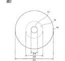
図1は、第1の実施の形態に係る光ファイバ10Bの断面図である。この光ファイバ10Bのコア領域11は半径αの円形であり、14.5mol%の濃度のGeが添加されたシリカガラス(屈折率n0=1.46567)で構成され、コア領域11の周囲には純粋シリカガラス(屈折率n2=1.44402)を材料とする外半径γのクラッド領域12が設けられている。クラッド領域12は、コア領域11を囲み、副媒質領域13(屈折率n3=1)を有する内側クラッド領域14と、内側クラッド領域14を囲み副媒質領域13を含まない外側クラッド領域15とから構成されている。内側クラッド領域14において、主媒質は純粋シリカガラスであり、副媒質領域13を形成する副媒質は空気である。副媒質領域13は、半径rの円形であり、半径β’の円周上に実質的に等間隔で8個配置されている。また、外側クラッド領域15のさらに外側には、ガラスやポリマー等の材料で構成されるジャケット層が被覆されている。このジャケット層は、マイクロベンドの発生抑止やファイバの強度向上といった機械的な性能向上を図るものであるが、外側クラッド領域15は十分に厚く、ジャケット層が光学特性に与える影響は無視できる。内側クラッド領域14と外側クラッド領域15の境界は、β=2β’−αなる半径を有する円周で定義する(これは、βがβ’とαの平均であること、つまり、副媒質領域13の中心は、内側クラッド領域14のコア領域11との境界および外側クラッド領域15との境界から径方向に等距離に位置していることを意味する)。FIG. 1 is a cross-sectional view of an optical fiber 10B according to the first embodiment. The
この光ファイバ10Bの構造パラメータは、次の通りである。すなわち、β’/α=1.94、r/α=0.135、γ/α=18.3である。 The structural parameters of the optical fiber 10B are as follows. That is, β ′ / α = 1.94, r / α = 0.135, and γ / α = 18.3.
ここで、前述したように、領域の内半径をa(コア領域の場合は0)、外半径をbとして、ファイバ断面内での位置を極座標で表し、この極座標を用いた断面内の屈折率分布をn(r、θ)で表すと、領域の平均屈折率navgは再掲する次式で与えられる。
この式から、所定の領域中に一様な屈折率nmを有する主媒質中にこれと異なる屈折率nsを有する副媒質で形成された副媒質領域が存在する場合、領域内のそれぞれの断面積をAm、Asとすると、この所定領域の平均屈折率navgは簡単に次式で表すことが可能である。
(2)式と上述の各パラメータから内側クラッド領域14の平均屈折率n1は1.4366となる。From the equation (2) and the above-described parameters, the average refractive index n1 of the
図2は、比較対象とする従来の不純物添加型光ファイバ10Aの断面図である。光ファイバ10Aのコア領域11の材料はGe濃度14.5mol%のシリカ、内側クラッド領域14の材料はF濃度1.113wt%のシリカ、外側クラッド領域15の材料は純シリカである。 FIG. 2 is a cross-sectional view of a conventional doped optical fiber 10A to be compared. The material of the
この光ファイバ10Aの構造パラメータは、次の通りである。すなわち、β/α=2.88、γ/α=18.3である。 The structural parameters of the optical fiber 10A are as follows. That is, β / α = 2.88 and γ / α = 18.3.
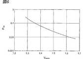
図3〜図6は、光ファイバ10A及び10Bにおいて、比率を一定に保ちながら寸法を変えることによってモードフィールド径を変化させたときの光学特性の変化を示す図である。図3及び図4における横軸はモードフィールド径MFDを示し、図3の縦軸は波長1550nmにおける波長分散D1550、図4の縦軸は波長1550nmにおける波長分散スロープS1550をそれぞれ示す。また、図5は、光ファイバ10Bにおける外側クラッド領域を伝搬する光パワーの割合POCと光学特性との関係を示す。図5の横軸は外側クラッド領域を伝搬する光パワーの割合Pocを示し、左縦軸及び右縦軸は波長1550nmにおける波長分散D1550及び波長分散スロープS1550をそれぞれ示す。図6は、光ファイバ10Bにおける外側クラッド領域を伝搬する光パワーの割合POCとファイバ寸法との関係を示し、横軸はコアのV値、縦軸は光パワーの割合Pocをそれぞれ示す。ここで、コアのV値とは寸法に比例する値であり、コア及び外側クラッドの屈折率をそれぞれn0及びn2、真空中での波数をkとして、
図3及び図4は、光ファイバ10Bが光ファイバ10Aに比べて絶対値の大きな負の分散及び波長分散スロープを有することをそれぞれ示している。例えばMFD=7μmのとき、光ファイバ10AではD1550=−90ps/nm/km、S1550=−0.25ps/nm2/kmであるのに対し、光ファイバ10BではD1550=−107ps/nm/km、S1550=−0.84ps/nm2/kmである。負の分散及び波長分散スロープの絶対値が大きいことにより、正の分散及び波長分散スロープの補償に要する長さが短くて済むため、光ファイバ10Bは光ファイバ10Aに比べて正分散及び波長分散スロープの補償に適しているといえる。3 and 4 show that the optical fiber 10B has a negative dispersion and a chromatic dispersion slope, which have a larger absolute value than the optical fiber 10A, respectively. For example, when MFD = 7 μm, D1550 = −90 ps / nm / km and S1550 = −0.25 ps / nm2 / km in the optical fiber 10A, whereas D1550 = −107 ps / nm in the optical fiber 10B. / Km, S1550 = −0.84 ps / nm2 / km. Since the absolute values of the negative dispersion and the chromatic dispersion slope are large, the length required for compensation of the positive dispersion and the chromatic dispersion slope can be shortened. Therefore, the optical fiber 10B has a positive dispersion and chromatic dispersion slope as compared with the optical fiber 10A. It can be said that it is suitable for compensation.
図5は、外側クラッド領域を伝搬する光パワーの割合Pocが0.008以上のときに、負の分散及び負の分散スロープが得られることを示している。また、外側クラッド領域を伝搬するパワーの割合Pocが0.1以上のときに、特に絶対値の大きな負の分散及び負の分散スロープが得られることを示している。なお、図6に示すように、Poc≧0.008を実現するためにはVcore≦1.63、Poc≧0.1を実現するためにはVcore≦1.34とされる。FIG. 5 shows that a negative dispersion and a negative dispersion slope can be obtained when the ratio Poc of the optical power propagating in the outer cladding region is 0.008 or more. Further, it is shown that negative dispersion and negative dispersion slope having a particularly large absolute value can be obtained when the ratio Poc of power propagating in the outer cladding region is 0.1 or more. As shown in FIG. 6, Vcore ≦ 1.63 is achieved in order to realize Poc ≧ 0.008, and Vcore ≦ 1.34 is achieved in order to realize Poc ≧ 0.1.
以上説明したように、第1の実施の形態に係る光ファイバ10Bは、従来の空気クラッド光ファイバと異なり、小さい(負に大きい)波長分散と、小さい(負に大きい)波長分散スロープとを実現することができる。また、波長分散及び波長分散スロープは、不純物添加型の光ファイバ10Aに比べて負に大きい。そのため、光伝送路が有する正の波長分散や正の波長分散スロープを補償する用途に好適である。また、複屈折も小さい。さらに、従来の微細構造光ファイバと異なり、コアのガラス屈折率がクラッドでのガラス屈折率よりも高いので、融着時に孔がつぶれることによる接続損失が少ない。また、孔の数も8と少ないため製造が容易であり、強度も高い。特に外側クラッドを伝搬するパワーの割合が0.1以上の時に、絶対値の大きな負の波長分散及び負の波長分散スロープが得られる。 As described above, the optical fiber 10B according to the first embodiment realizes a small (negatively large) chromatic dispersion and a small (negatively large) chromatic dispersion slope, unlike the conventional air-clad optical fiber. can do. Further, the chromatic dispersion and the chromatic dispersion slope are negatively larger than those of the impurity-added optical fiber 10A. Therefore, it is suitable for the use which compensates the positive chromatic dispersion and positive chromatic dispersion slope which an optical transmission line has. Moreover, birefringence is also small. Further, unlike the conventional microstructured optical fiber, since the glass refractive index of the core is higher than the glass refractive index of the cladding, the connection loss due to the collapse of the holes at the time of fusion is small. In addition, since the number of holes is as small as 8, manufacture is easy and strength is high. In particular, when the ratio of power propagating through the outer cladding is 0.1 or more, negative chromatic dispersion and negative chromatic dispersion slope having a large absolute value can be obtained.
(第2の実施の形態) (Second Embodiment)
図7及び図8は、本発明の第2の実施の形態に係る光ファイバ10E、10F及び10Gの断面図である。コア領域30と内側クラッド領域31は、Ge添加されたシリカガラス(屈折率n0)によって形成され、内側クラッド領域31は、副媒質領域32(屈折率n3)を複数有する。内側クラッド領域31において、主媒質はGe添加されたシリカガラス(n0=1.46567)であり、副媒質領域32を形成する副媒質は空気(n3=1)である。副媒質領域32は、半径rの円形であり、半径β’の円周上に実質的に等間隔で配置されている。内側クラッド領域の外周は半径βの円周である。コア領域30と内側クラッド領域31の境界は半径α=2β’−βの円周で定義する。外側クラッド領域33は、純粋シリカガラスで形成されている。比較対象として、図2に示す不純物添加型光ファイバ10Aを用いる。7 and 8 are cross-sectional views of optical fibers 10E, 10F, and 10G according to the second embodiment of the present invention. The
図7に示す光ファイバ10E及び10Fの構造パラメータは、次の通りである。すなわち、光ファイバ10Eについては、α=1.02μm、β’=1.97μm、r=0.253μmである。このとき、内側クラッド領域31の平均屈折率n1は1.43883となる。また、光ファイバ10Fについては、α=1.25μm、β’=1.87μm、r=0.215μmである。このとき、内側クラッド領域31の平均屈折率n1は1.43395となる。The structural parameters of the optical fibers 10E and 10F shown in FIG. 7 are as follows. That is, for the optical fiber 10E, α = 1.02 μm, β ′ = 1.97 μm, and r = 0.253 μm. At this time, the average refractive index n1 of the
また、図8に示す光ファイバ10Gについては、α=1.50μm、β’=1.84μm、r=0.155μmである。このとき、内側クラッド領域31の平均屈折率n1は1.4211となる。For the optical fiber 10G shown in FIG. 8, α = 1.50 μm, β ′ = 1.84 μm, and r = 0.155 μm. At this time, the average refractive index n1 of the
次に、以上のような構造を持つ第2の実施の形態に係る光ファイバ10E〜10Gの光波長λと、波長分散Dと、実効コア断面積Aeffとの関係の計算結果を図9に示す。横軸が光波長λ、左側縦軸が波長分散D,右側縦軸が実効コア断面積Aeffとなっている。光ファイバ10A、10E、10F及び10Gのいずれも、波長1550nmにおいて、実効コア断面積Aeff=30μm2であるが、波長分散Dは、光ファイバ10Aが−155ps/nm/km、光ファイバ10Eが−164ps/nm/km、光ファイバ10Fが−208ps/nm/km、光ファイバ10Gが−254ps/nm/kmの順で負に大きくなっている。また、波長増加に対する実効コア断面積Aeffの増加ペースに注目すると、光ファイバ10E及び10Fの波長増加に対する実効コア断面積Aeffの増加ペースは、光ファイバ10Aの波長増加に対する実効コア断面積Aeffの増加ペースよりも小さい。波長増加に対する実効コア断面積Aeffの増加ペースが小さいということは、光がコアに良く閉じ込められており、曲げ損失が小さいことを意味する。また、一般に、実効コア断面積Aeffを大きくすると曲げ損失も大きくなることから、曲げ損失を一定にして比較すると、光ファイバ10E及び10Fは、光ファイバ10Aよりも大きい実効コア断面積Aeffを実現することができる。また、光ファイバ10E、10F及び10Gのいずれも、副媒質領域の配置が4回回転対称性を実質的に有するので、2つの偏波モードが縮退し、モード複屈折が小さい。Next, FIG. 9 shows the calculation result of the relationship between the optical wavelength λ, the chromatic dispersion D, and the effective core area Aeff of the optical fibers 10E to 10G according to the second embodiment having the above structure. Show. The horizontal axis represents the optical wavelength λ, the left vertical axis represents the chromatic dispersion D, and the right vertical axis represents the effective core area Aeff . Each of the optical fibers 10A, 10E, 10F, and 10G has an effective core area Aeff = 30 μm2 at a wavelength of 1550 nm, but the chromatic dispersion D is −155 ps / nm / km for the optical fiber 10A and the optical fiber 10E. -164 ps / nm / km, the optical fiber 10F is negatively increased in the order of -208 ps / nm / km, and the optical fiber 10G is -254 ps / nm / km. Further, paying attention to increase the pace of the effective core area Aeff with respect to wavelength increases, increasing the pace of the effective core area Aeff with respect to wavelength increases in the optical fiber 10E and 10F, the effective core area with respect to the wavelength increases in the optical fiber 10A AIt is smaller than the increasing pace ofeff . The fact that the increase rate of the effective core area Aeff with respect to the wavelength increase is small means that the light is well confined in the core and the bending loss is small. In general, when the effective core area Aeff is increased, the bending loss increases. Therefore, when the bending loss is made constant, the optical fibers 10E and 10F have an effective core area Aeff larger than that of the optical fiber 10A. Can be realized. Further, in any of the optical fibers 10E, 10F, and 10G, the arrangement of the sub-medium region substantially has a 4-fold rotational symmetry, so that the two polarization modes are degenerated and the mode birefringence is small.
従って、第2の実施の形態に係る光ファイバ10E〜10Gは、図2に示す不純物添加型光ファイバ10Aに比べて、小さい(負に大きい)波長分散と、小さい曲げ損失と、大きい実効コア断面積とを実現することができる。波長分散が負に大きいため、正分散の補償に必要な長さが短く、かつ実効コア断面積が大きい。そのため、図10に示すような、光送信器50と、光受信器51と、正分散光ファイバ52と、負分散光ファイバ53を含む光通信システムにおいて、第2の実施の形態に係る光ファイバを負分散光ファイバとして用いれば、負分散光ファイバにおける非線型光学効果による伝送路品質劣化を抑制し、大容量の光通信システムを実現することができる。 Therefore, the optical fibers 10E to 10G according to the second embodiment are smaller (negatively larger) chromatic dispersion, smaller bending loss, and larger effective core breakage than the doped optical fiber 10A shown in FIG. Area. Since the chromatic dispersion is negatively large, the length necessary for compensating the positive dispersion is short and the effective core area is large. Therefore, in the optical communication system including the
本発明に係る光ファイバでは、内側クラッド領域を構成する主媒質に加えて、この主媒質と異なる屈折率を有する副媒質からなる領域を内側クラッド領域に導入する。一方、外側クラッド領域は実質的に均一な媒質で構成され、副媒質領域を含まない。主媒質よりも屈折率の低い副媒質からなる領域を導入することにより、内側クラッド領域の平均屈折率を副媒質領域が無い場合に比べて大きく下げることができる。その結果、従来の不純物添加型光ファイバに比べて負に大きな分散や、負に大きな分散スロープや、大きな実効コア断面積や、小さな曲げ損失といった好ましい特性を得ることができる。また、本発明の光ファイバは、空気クラッド光ファイバと異なり、負に大きな分散や、負に大きな分散スロープを実現することができる。これは、副媒質領域を含む内側クラッド領域を囲む外側クラッド領域が、光学特性、とりわけ波長分散特性に影響を及ぼすためである。さらに、外側クラッド領域が実質的に均一な媒質で構成され、副媒質領域を含まないため、導入する副媒質領域の数を、従来の微細構造光ファイバに比べて大幅に減らすことができる。そのため、シリカ管を配列する製造方法、又は穿孔器具を用いてプリフォームに孔をあける製造方法のいずれを用いるにせよ、再現性良く製造することが容易となり、製造コストも低減することができる。 In the optical fiber according to the present invention, in addition to the main medium constituting the inner cladding region, a region made of a sub-medium having a refractive index different from that of the main medium is introduced into the inner cladding region. On the other hand, the outer cladding region is composed of a substantially uniform medium and does not include the sub-medium region. By introducing a region made of a sub-medium having a lower refractive index than that of the main medium, the average refractive index of the inner cladding region can be greatly lowered as compared with the case where there is no sub-medium region. As a result, favorable characteristics such as negatively large dispersion, negatively large dispersion slope, large effective core cross-sectional area, and small bending loss can be obtained as compared with the conventional impurity-doped optical fiber. Further, unlike the air-clad optical fiber, the optical fiber of the present invention can realize negatively large dispersion and negatively large dispersion slope. This is because the outer cladding region surrounding the inner cladding region including the sub-medium region affects the optical characteristics, particularly the wavelength dispersion characteristics. Furthermore, since the outer cladding region is formed of a substantially uniform medium and does not include the sub-medium region, the number of sub-medium regions to be introduced can be greatly reduced as compared with the conventional microstructured optical fiber. Therefore, it is easy to manufacture with good reproducibility and the manufacturing cost can be reduced, regardless of which one of the manufacturing method for arranging the silica tubes or the manufacturing method for making holes in the preform using a drilling device.
また、特に副媒質領域が空孔である場合、副媒質領域の数の減少により、従来の微細構造光ファイバに比べて張力や側圧に対する強度が向上すると共に、空孔表面のOH基や空孔内の水蒸気による吸収損失の発生の可能性が減少することによって製造や接続が容易になる。さらに、コア領域の屈折率が外側クラッド領域の屈折率よりも高いので、内側クラッドにおいて孔がつぶれた場合であっても光導波特性が失われず、融着損失を低減することができる。 In particular, when the sub-medium region is a hole, the number of sub-medium regions is reduced, so that the strength against tension and lateral pressure is improved as compared with the conventional microstructured optical fiber, and OH groups and holes on the surface of the hole are improved. Manufacturing and connection are facilitated by reducing the possibility of absorption loss due to water vapor inside. Furthermore, since the refractive index of the core region is higher than the refractive index of the outer cladding region, the optical waveguide characteristics are not lost even when the hole is crushed in the inner cladding, and the fusion loss can be reduced.
なお、副媒質領域は、ファイバ軸を中心とする4回回転対称性が実質的に成立するように配置されていても良い。これにより、2つの偏波モードを実質的に縮退させ、複屈折を小さくすることができる。また、ファイバ軸を中心とする1個以上の同心円の円周上に実質的に等間隔で配置されていても良い。これにより、2つの偏波モードを実質的に縮退させ、複屈折を小さくすることができる。また、円周に沿って副媒質領域を配置することにより、この円周を含む円環領域の屈折率を一様に変化させたのと同等の効果を得ることができる。このため、従来の不純物添加型光ファイバと同様に、半径方向の屈折率プロファイルに基づく設計が可能となる。従って、系統的な設計が容易となる。また、ファイバ軸を中心とする円の円周上に実質的に等間隔で配置されていても良い。2つの偏波モードを実質的に縮退させ、複屈折を小さくすることができる。また、系統的な設計が容易となる。さらに、副媒質領域の数を最小限に抑えることにより、製造の容易性、高い強度、高い信頼性を実現することが可能となる。 Note that the sub-medium region may be arranged so that four-fold rotational symmetry about the fiber axis is substantially established. Thereby, two polarization modes can be degenerated substantially and birefringence can be made small. Moreover, you may arrange | position at substantially equal intervals on the circumference of the 1 or more concentric circle centering on a fiber axis. Thereby, two polarization modes can be degenerated substantially and birefringence can be made small. Further, by arranging the sub-medium region along the circumference, it is possible to obtain the same effect as changing the refractive index of the annular region including the circumference uniformly. For this reason, the design based on the refractive index profile in the radial direction is possible as in the conventional impurity-doped optical fiber. Therefore, systematic design becomes easy. Further, they may be arranged at substantially equal intervals on the circumference of a circle centered on the fiber axis. The two polarization modes can be substantially degenerated and the birefringence can be reduced. In addition, systematic design is facilitated. Furthermore, by minimizing the number of sub-medium regions, it is possible to realize ease of manufacture, high strength, and high reliability.
また、本実施の形態に係る光ファイバは、波長1550nmにおける外側クラッド領域を伝搬する光パワーの割合を0.008以上(より好ましくは0.1以上)とすることができる。そのため、外側クラッド領域を単なる機械的強度の向上等のための領域ではなく、光ファイバの光学特性(とりわけ波長分散特性)に現実的に影響を及ぼす領域とすることができる。特に、外側クラッド領域を伝搬する光パワーの割合が0.008以上であることにより、小さい(負に大きい)波長分散スロープを実現できる。また、外側クラッド領域を伝搬する光パワーの割合が0.1以上であることにより、小さい(負に大きい)波長分散を実現できる。 In the optical fiber according to the present embodiment, the ratio of the optical power propagating through the outer cladding region at the wavelength of 1550 nm can be 0.008 or more (more preferably 0.1 or more). For this reason, the outer cladding region can be a region that actually affects the optical characteristics (especially wavelength dispersion characteristics) of the optical fiber, not just a region for improving mechanical strength. In particular, when the ratio of the optical power propagating in the outer cladding region is 0.008 or more, a small (negatively large) chromatic dispersion slope can be realized. Further, when the ratio of the optical power propagating through the outer cladding region is 0.1 or more, small (negatively large) chromatic dispersion can be realized.
さらに、コア領域の媒質と、内側クラッド領域の主媒質と、外側クラッド領域の媒質とは、不純物が添加される場合がある石英系ガラスであり、内側クラッド領域における副媒質領域を形成する副媒質は気体又は真空である構成を採っても良い。これにより、伝送損失を低く抑えると共に、内側クラッドの平均屈折率を大きく低下させて、従来の不純物添加型光ファイバに比べて負に大きな分散などの好ましい特性を実現することが可能となる。 Furthermore, the medium in the core region, the main medium in the inner cladding region, and the medium in the outer cladding region are quartz-based glass to which impurities may be added, and the sub-medium that forms the sub-medium region in the inner cladding region. May adopt a gas or vacuum configuration. As a result, it is possible to reduce the transmission loss and reduce the average refractive index of the inner cladding greatly, thereby realizing desirable characteristics such as negative dispersion that is larger than that of a conventional impurity-doped optical fiber.
(第3の実施の形態) (Third embodiment)
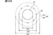
図11は、本発明の第3の実施の形態に係る光ファイバ10Hのファイバ軸方向の断面図である。また、図12Aは、図11における光ファイバをI−I線で切断した断面図であり、図12Bは、図11における光ファイバをII−II線で切断した断面図である。第3の実施の形態に係る光ファイバ10Hは、ファイバ軸方向に区間aと区間bとが交互に配置されており、区間aでは内側クラッド領域44に空孔43を含むが、区間bでは空孔43を含まない。区間aと区間bの間には、遷移区間cが存在し、遷移区間cでは空孔断面積がファイバ幅方向に変化している。区間aと区間bの長さは、典型的には100m以上である。一方、遷移区間cの長さは1m以下とすることができる。この時、遷移区間cの光学特性が光ファイバ全体の光学特性に及ぼす影響は無視できる。コア領域41の直径は2αであり、区間a及び区間bにおいて同一の値である。図12Aに示すように、区間aでは、ファイバ軸を中心とする半径β’の円周上に8個の空孔43(半径r)が等間隔で配置されている。区間aにおける屈折率分布は、空孔43を含む円環領域であるディプレスト部を有する屈折率分布に相当し、区間bにおける屈折率分布は、ディプレスト部を有さない屈折率分布に相当する。また、第1及び第2の実施の形態と同様に、内側クラッド領域44の外半径はβ=2β’−αとし、外側クラッド領域45の外半径はγとする。 FIG. 11 is a sectional view in the fiber axis direction of an optical fiber 10H according to the third embodiment of the present invention. 12A is a cross-sectional view of the optical fiber in FIG. 11 cut along line II, and FIG. 12B is a cross-sectional view of the optical fiber in FIG. 11 cut along line II-II. In the optical fiber 10H according to the third embodiment, the sections a and b are alternately arranged in the fiber axis direction. In the section a, the
この光ファイバ10Hの構造パラメータは、次の通りである。すなわち、α=1.70μm、β’=2.74μm、r=0.25μmである。コア領域41は、Ge濃度12mol%のシリカ、内側クラッド領域44の主媒質はGe濃度5.0mol%のシリカ、外側クラッド領域45は純シリカである。区間aでは空孔43を含むのに対し、区間bでは空孔43を含まないため、内側クラッド領域44の平均屈折率n1は、区間aにおいて1.435、区間bにおいて1.452であり、ファイバ軸方向に変化した状態となっている。The structural parameters of the optical fiber 10H are as follows. That is, α = 1.70 μm, β ′ = 2.74 μm, and r = 0.25 μm. The
図13は、光ファイバ10Hの区間a及び区間bの波長分散特性の数値シミュレーション結果を示す図である。ここでは、図13に示すように、波長範囲を1510nmから1600nmとした。区間aでは、負の波長分散と負の波長分散スロープとを有し、区間bでは、正の波長分散と正の波長分散スロープとを有する。特に、波長1550nmにおける波長分散D及び波長分散ロープSは、
区間aでは、
D=−12.8ps/nm/km、
S=−0.129ps/nm2/kmであり、
区間bでは、
D=+6.16ps/nm/km、
S=+0.065ps/nm2/kmである。FIG. 13 is a diagram illustrating a numerical simulation result of chromatic dispersion characteristics in the section a and the section b of the optical fiber 10H. Here, as shown in FIG. 13, the wavelength range was set to 1510 nm to 1600 nm. The section a has negative chromatic dispersion and a negative chromatic dispersion slope, and the section b has positive chromatic dispersion and a positive chromatic dispersion slope. In particular, the chromatic dispersion D and the chromatic dispersion rope S at a wavelength of 1550 nm are
In section a,
D = −12.8 ps / nm / km,
S = −0.129 ps / nm2 / km,
In section b,
D = + 6.16 ps / nm / km,
S = + 0.065 ps / nm2 / km.
また、1550nmにおいて、外側クラッド領域を伝搬する光パワーの割合POCは0.048である。At 1550 nm, the ratio POC of the optical power propagating through the outer cladding region is 0.048.
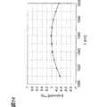
図14は、長さ1の区間bに対して、長さ0.48の区間aを組み合わせた場合の平均波長分散Davgを示す図である。ここで、波長分散Di、長さLiのファイバ区間i(i=1,2,・・・n)が連結されているとき、連結されたファイバ区間全体の平均波長分散Davgを次式で定義する。また、連結されたファイバ区間全体の長さをLとして、累積波長分散をDavgLで定義する。
同様にして、波長分散スロープSi、長さLiのファイバ区間i(i=1,2,・・・n)が連結されているとき、連結されたファイバ区間全体の平均波長分散スロープSavgを次式で定義する。また、累積波長分散スロープをSavgLで定義する。
波長分散が一定であるとみなすことができるファイバ区間における波長分散を局所波長分散と呼ぶ。これは、このようなファイバ区間が複数接続された伝送路全体での累積波長分散と区別するためである。 The chromatic dispersion in the fiber section where the chromatic dispersion can be regarded as constant is called local chromatic dispersion. This is for distinguishing from the accumulated chromatic dispersion in the entire transmission line in which a plurality of such fiber sections are connected.
図14に示されるように、平均波長分散Davg及び平均波長分散スロープSavgは、波長1550nmにおいて実質的にゼロとなる。そのため、上記の比率で区間a及び区間bを有する光ファイバ伝送路では、1510nmから1600nmの広い波長帯域において平均波長分散の絶対値が0.4ps/nm/km以下となる。一方、図13に示されるように局所波長分散の絶対値は4ps/nm/km以上と大きい。また、遷移区間に含まれる一部のファイバ区間においては局所波長分散の絶対値が小さくなるが、このようなファイバ区間の長さは短く(例えば、1m以下)できるので、遷移区間における非線形光学現象の影響は無視できる大きさである。従って、累積分散による光パルス広がりと、異なる波長の光信号間の非線形光学現象による伝送品質劣化を同時に抑制することができる。As shown in FIG. 14, the average chromatic dispersion Davg and the average chromatic dispersion slope Savg are substantially zero at the wavelength of 1550 nm. Therefore, in the optical fiber transmission line having the section a and the section b at the above ratio, the absolute value of the average chromatic dispersion is 0.4 ps / nm / km or less in a wide wavelength band from 1510 nm to 1600 nm. On the other hand, as shown in FIG. 13, the absolute value of local chromatic dispersion is as large as 4 ps / nm / km or more. In addition, although the absolute value of local chromatic dispersion is small in some fiber sections included in the transition section, since the length of such a fiber section can be shortened (for example, 1 m or less), the nonlinear optical phenomenon in the transition section. The effect of is negligible. Therefore, it is possible to simultaneously suppress the spread of the optical pulse due to the accumulated dispersion and the transmission quality deterioration due to the nonlinear optical phenomenon between the optical signals of different wavelengths.
このように、第3の実施の形態に係る光ファイバでは、ファイバ断面内の屈折率分布をファイバ軸方向に大きく変化させることができるため、波長分散の対波長特性をファイバ軸方向に大きく変化させることができる。そのため、1種類のファイバ区間からなる光ファイバでは実現が困難又は不可能である波長分散特性を実現することができる。特に、局所波長分散の絶対値が大きく、累積波長分散の絶対値が小さいという特性を実現することができる。 As described above, in the optical fiber according to the third embodiment, since the refractive index distribution in the fiber cross section can be greatly changed in the fiber axis direction, the chromatic dispersion versus wavelength characteristic is greatly changed in the fiber axis direction. be able to. Therefore, it is possible to realize chromatic dispersion characteristics that are difficult or impossible to realize with an optical fiber composed of one type of fiber section. In particular, a characteristic that the absolute value of local chromatic dispersion is large and the absolute value of cumulative chromatic dispersion is small can be realized.
また、本実施の形態に係る光ファイバでは、従来の分散マネジメントファイバに比べて、ファイバ断面内の屈折率分布をファイバ軸方向に大きく変化させることによって、波長分散の対波長特性をファイバ軸方向に大きく変化させることができる。そのため、1510nm〜1600nmの波長帯における波長分散が−10ps/nm/kmより小さいファイバ区間aと、その波長帯における波長分散が+5ps/nm/kmより大きいファイバ区間をbとを有し、その波長帯における平均波長分散の絶対値が0.4ps/nm/kmよりも小さく、その波長帯においてファイバ区間aの波長分散スロープが負であると共にファイバ区間bの波長分散スロープが正である光ファイバを実現することができる。その結果、従来技術に比べて、累積波長分散の絶対値が所定の値よりも小さくなる波長範囲を拡大し、伝送容量を拡大することができる。 In addition, in the optical fiber according to the present embodiment, the refractive index distribution in the fiber cross section is largely changed in the fiber axis direction as compared with the conventional dispersion management fiber, so that the wavelength characteristic of chromatic dispersion in the fiber axis direction is changed. It can be changed greatly. Therefore, it has a fiber section a in which the chromatic dispersion in the wavelength band of 1510 nm to 1600 nm is smaller than −10 ps / nm / km, and a fiber section in which the chromatic dispersion in the wavelength band is larger than +5 ps / nm / km, and b An optical fiber in which the absolute value of the average chromatic dispersion in the band is smaller than 0.4 ps / nm / km, the chromatic dispersion slope in the fiber section a in the wavelength band is negative, and the chromatic dispersion slope in the fiber section b is positive. Can be realized. As a result, the wavelength range in which the absolute value of the accumulated chromatic dispersion is smaller than a predetermined value can be expanded and the transmission capacity can be expanded as compared with the prior art.
さらに、本実施の形態に係る光ファイバは、空孔を含まない複数の区間bがファイバ軸方向に間隔をおいて配置されている。その結果、区間bにおいて光ファイバをクリーブし、他の光ファイバと融着接続できる。この時、従来の微細構造光ファイバと異なり、融解による副媒質領域の変形・消失や、副媒質領域によるコアの認識の妨害の問題が起こらないので、従来の微細構造光ファイバに比べて融着接続が容易になる。また、端面において外気に対して開いた空孔がなく、汚染物質が空孔に侵入しない。そのため、屈折率マッチング液を用いて低損失の機械的接続を実現することができる。さらに、一部のファイバ区間aにおいて側面が損傷し、空孔内に水などの汚染物質が侵入した場合も汚染物質はファイバ全体には行き渡らないため、損傷に対する耐性が従来の微細構造光ファイバに比べて高い。 Furthermore, in the optical fiber according to the present embodiment, a plurality of sections b that do not include holes are arranged at intervals in the fiber axis direction. As a result, the optical fiber is cleaved in the section b, and can be fusion-spliced with another optical fiber. At this time, unlike the conventional microstructured optical fiber, there is no problem of deformation / disappearance of the sub-medium region due to melting and interference of core recognition due to the sub-medium region. Connection becomes easy. Further, there is no hole open to the outside air at the end face, and the contaminant does not enter the hole. Therefore, a low-loss mechanical connection can be realized using the refractive index matching liquid. Further, even if the side surface is damaged in some fiber sections a and contaminants such as water enter the pores, the contaminants do not spread throughout the fiber, so that the resistance to damage is the same as that of the conventional microstructured optical fiber. Higher than that.
(第4の実施の形態) (Fourth embodiment)
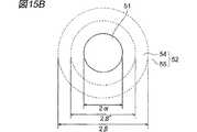
図15A及び図15Bは、それぞれ本発明の第4の実施の形態に係る光ファイバ10Iの区間a及び区間bにおける断面図である。第4の実施の形態に係る光ファイバ10Iは、第3の実施の形態に係る光ファイバ10Hと同様に、ファイバ軸方向に区間aと区間bとが交互に配置されており、区間aでは内側クラッド領域54に空孔53を含むが、区間bでは空孔53を含まない。区間aと区間bの間には、遷移区間cが存在し、遷移区間cでは空孔断面積がファイバ幅方向に変化している。区間aと区間bの長さは、典型的には100m以上である。一方、遷移区間cの長さは1m以下とすることができる。この時、遷移区間cの光学特性が光ファイバ全体の光学特性に及ぼす影響は無視できる。コア領域51の直径は2αであり、区間a及び区間bにおいて同一の値である。図15Aに示すように、区間aでは、ファイバ軸を中心とする半径β’の円周上に8個の空孔53(半径r)が等間隔で配置されている。区間aにおける屈折率分布は、空孔53を含む円環領域であるディプレスト部を有する屈折率分布に相当し、区間bにおける屈折率分布は、ディプレスト部を有さない屈折率分布に相当する。また、第1〜第3の実施の形態と同様に、内側クラッド領域54の外半径はβ=2β’−αとする。 FIG. 15A and FIG. 15B are cross-sectional views in the section a and the section b of the optical fiber 10I according to the fourth embodiment of the present invention, respectively. In the optical fiber 10I according to the fourth embodiment, similarly to the optical fiber 10H according to the third embodiment, the sections “a” and “b” are alternately arranged in the fiber axis direction. The
この光ファイバ10Iの構造パラメータは、次の通りである。すなわち、α=1.74μm、β’=2.81μm、r=0.39μmである。コア領域51は、Ge濃度14mol%のシリカ(屈折率n0=1.465)、内側クラッド領域54の主媒質及び外側クラッド領域55は純シリカ(屈折率n2及びn3=1.444)である。区間aでは空孔43を含むのに対し、区間bでは空孔43を含まないため、内側クラッド領域54の平均屈折率n1は、ファイバ軸方向に変化した状態となっている。The structural parameters of the optical fiber 10I are as follows. That is, α = 1.74 μm, β ′ = 2.81 μm, and r = 0.39 μm. The
図16は、光ファイバ10Iの区間a及び区間bの波長分散特性の数値シミュレーション結果を示す図である。ここでは、図16に示すように、波長範囲を1510nmから1600nmとした。区間aでは、正の波長分散と負の波長分散スロープとを有し、区間bでは、負の波長分散と正の波長分散スロープとを有する。特に、波長1550nmにおける波長分散D及び波長分散ロープSは、
区間aでは、
D=+29.7ps/nm/km、
S=−0.079ps/nm2/kmであり、
区間bでは、D=−12.4ps/nm/km、
S=+0.033ps/nm2/kmである。FIG. 16 is a diagram illustrating a numerical simulation result of chromatic dispersion characteristics in the section a and the section b of the optical fiber 10I. Here, as shown in FIG. 16, the wavelength range was set to 1510 nm to 1600 nm. Section a has positive chromatic dispersion and negative chromatic dispersion slope, and section b has negative chromatic dispersion and positive chromatic dispersion slope. In particular, the chromatic dispersion D and the chromatic dispersion rope S at a wavelength of 1550 nm are
In section a,
D = + 29.7 ps / nm / km,
S = −0.079 ps / nm2 / km,
In section b, D = −12.4 ps / nm / km,
S = + 0.033 ps / nm2 / km.
また、1550nmにおいて、外側クラッドを伝搬する光パワーの割合POCは0.0081である。At 1550 nm, the ratio POC of the optical power propagating through the outer cladding is 0.0081.
図17は、長さ1の区間bに対して、長さ0.42の区間aを組み合わせた場合の平均波長分散Davgを示す図である。平均波長分散Davg及び平均波長分散スロープSavgは、波長1550nmにおいて実質的にゼロとなる。そのため、上記の比率で区間a及び区間bを有する光ファイバ伝送路では、1510nmから1600nmの広い波長帯域において平均波長分散の絶対値が1ps/nm/km以下となる。一方、図16に示されるように局所波長分散の絶対値は10ps/nm/km以上と大きい。従って、累積分散による光パルス広がりと、異なる波長の光信号間の非線形光学現象による伝送品質劣化を同時に抑制することができる。FIG. 17 is a diagram illustrating an average chromatic dispersion Davg when a section a having a length of 0.42 is combined with a section b having a length of 1. The average chromatic dispersion Davg and the average chromatic dispersion slope Savg are substantially zero at the wavelength of 1550 nm. Therefore, in the optical fiber transmission line having the section a and the section b at the above ratio, the absolute value of the average chromatic dispersion is 1 ps / nm / km or less in a wide wavelength band from 1510 nm to 1600 nm. On the other hand, as shown in FIG. 16, the absolute value of local chromatic dispersion is as large as 10 ps / nm / km or more. Therefore, it is possible to simultaneously suppress the spread of the optical pulse due to the accumulated dispersion and the transmission quality deterioration due to the nonlinear optical phenomenon between the optical signals of different wavelengths.
このように、第4の実施の形態に係る光ファイバでも、ファイバ断面内の屈折率分布をファイバ軸方向に大きく変化させることができるため、波長分散の対波長特性をファイバ軸方向に大きく変化させることができる。そのため、1種類のファイバ区間からなる光ファイバでは実現が困難又は不可能である波長分散特性を実現することができる。特に、局所波長分散の絶対値が大きく、累積波長分散の絶対値が小さいという特性を実現することができる。 As described above, also in the optical fiber according to the fourth embodiment, since the refractive index distribution in the fiber cross section can be greatly changed in the fiber axis direction, the chromatic dispersion versus wavelength characteristic is greatly changed in the fiber axis direction. be able to. Therefore, it is possible to realize chromatic dispersion characteristics that are difficult or impossible to realize with an optical fiber composed of one type of fiber section. In particular, a characteristic that the absolute value of local chromatic dispersion is large and the absolute value of cumulative chromatic dispersion is small can be realized.
また、波長分散の対波長特性のファイバ軸方向における変化を適切に設計することにより、1510nm〜1600nmの波長帯における波長分散が20ps/nm/kmより大きいファイバ区間aと、その波長帯における波長分散が−10ps/nm/kmより小さいファイバ区間bとを有し、その波長帯における平均波長分散の絶対値が1ps/nm/kmよりも小さくなる光ファイバを実現することができる。本実施の形態に係る光ファイバでは、従来の分散マネジメントファイバに比べてファイバ断面内の屈折率分布をファイバ軸方向に大きく変化させることによって、波長分散の対波長特性をファイバ軸方向に大きく変化させることができるので、各区間における局所波長分散の絶対値を従来技術よりも大きくすることができる。その結果、累積波長分散による光パルス広がりを抑制すると同時に、異なる波長の光信号間での非線形光学現象による伝送品質劣化を従来技術よりも小さくすることができる。 Further, by appropriately designing the change in the fiber axis direction of chromatic dispersion versus wavelength characteristics, a fiber section a having a chromatic dispersion greater than 20 ps / nm / km in the wavelength band of 1510 nm to 1600 nm, and the chromatic dispersion in that wavelength band And an optical fiber having a fiber section b smaller than −10 ps / nm / km and an absolute value of average chromatic dispersion in the wavelength band smaller than 1 ps / nm / km. In the optical fiber according to the present embodiment, the refractive index distribution in the fiber cross section is largely changed in the fiber axis direction as compared with the conventional dispersion management fiber, so that the wavelength characteristic of chromatic dispersion is greatly changed in the fiber axis direction. Therefore, the absolute value of the local chromatic dispersion in each section can be made larger than that in the prior art. As a result, it is possible to suppress the optical pulse spread due to the accumulated chromatic dispersion and at the same time reduce the transmission quality degradation due to the nonlinear optical phenomenon between the optical signals of different wavelengths as compared with the prior art.
さらに、本実施の形態に係る光ファイバでは、従来の分散マネジメントファイバに比べて、ファイバ断面内の屈折率分布をファイバ軸方向に大きく変化させることによって、波長分散の対波長特性をファイバ軸方向に大きく変化させることができる。そのため、1510nm〜1600nmの波長帯における波長分散が20ps/nm/kmより大きいファイバ区間aと、その波長帯における波長分散が−10ps/nm/kmより小さいファイバ区間をbとを有し、その波長帯における平均波長分散の絶対値が1ps/nm/kmよりも小さく、その波長帯においてファイバ区間aの波長分散スロープが負であると共にファイバ区間bの波長分散スロープが正である光ファイバを実現することができる。その結果、従来技術に比べて、累積波長分散の絶対値が所定の値よりも小さくなる波長範囲を拡大し、伝送容量を拡大することができる。 Furthermore, in the optical fiber according to the present embodiment, the refractive index distribution in the fiber cross section is greatly changed in the fiber axis direction, compared with the conventional dispersion management fiber, so that the wavelength characteristic of chromatic dispersion in the fiber axis direction is changed. It can be changed greatly. Therefore, it has a fiber section a in which the chromatic dispersion in the wavelength band of 1510 nm to 1600 nm is larger than 20 ps / nm / km, and a fiber section in which the chromatic dispersion in the wavelength band is smaller than −10 ps / nm / km, and b An optical fiber in which the absolute value of the average chromatic dispersion in the band is smaller than 1 ps / nm / km, the chromatic dispersion slope in the fiber section a in the wavelength band is negative, and the chromatic dispersion slope in the fiber section b is positive is realized. be able to. As a result, the wavelength range in which the absolute value of the accumulated chromatic dispersion is smaller than a predetermined value can be expanded and the transmission capacity can be expanded as compared with the prior art.
以上説明したように、本発明に係る光ファイバは、実質的に均一な媒質で構成されるコア領域と、コア領域を包囲する内側クラッド領域と、内側クラッド領域を包囲し、実質的に均一な媒質で構成される外側クラッド領域とを有し、コア領域、内側クラッド領域、及び外側クラッド領域は、ファイバ軸に沿って伸び、コア領域の平均屈折率n0と、内側クラッド領域の平均屈折率n1と、外側クラッド領域の平均屈折率n2との間に、n1<n2<n0なる関係が成立する光ファイバにおいて、内側クラッド領域を構成する主媒質とは異なる屈折率を有する副媒質からなりファイバ軸に沿って伸びる副媒質領域が、内側クラッド領域に3個以上含まれる構成を採る。As described above, the optical fiber according to the present invention includes a core region composed of a substantially uniform medium, an inner cladding region surrounding the core region, and an inner cladding region. An outer cladding region composed of a medium, and the core region, the inner cladding region, and the outer cladding region extend along the fiber axis, and the average refractive index n0 of the core region and the average refractive index of the inner cladding region In an optical fiber in which a relationship of n1 <n2 <n0 is established between n1 and the average refractive index n2 of the outer cladding region, the optical fiber has a refractive index different from that of the main medium constituting the inner cladding region. A configuration is adopted in which three or more sub-medium regions made of the sub-medium and extending along the fiber axis are included in the inner cladding region.
このような構成により、内側クラッド領域の平均屈折率を、副媒質領域が無い場合に比べて大きく下げることができるため、従来の不純物添加型光ファイバに比べて大きな負分散、大きな負分散スロープ、大きな実行コア断面積、及び小さな曲げ損失を実現することが可能となる。また、従来の空気クラッド光ファイバと異なり、外側クラッド領域が光学特性に影響を及ぼす結果、従来の空気クラッド光ファイバに比べて大きな負分散及び大きな負分散スロープを実現できる。また、導入する副媒質領域の数を大幅に減らすことができるため、再現性良く製造することが容易となり、製造コストも低減できる。また、従来の微細構造光ファイバに比べて張力や側圧に対する強度が向上すると共に、空孔表面のOH基や空孔内の水蒸気による吸収損失の発生の可能性が減少することによって製造や接続が容易になる。さらに、コア領域の屈折率が外側クラッド領域の屈折率よりも高いので、内側クラッドの孔がつぶれた場合であっても光導波特性が失われず、融着損失を低減させることができる。 With such a configuration, the average refractive index of the inner cladding region can be greatly reduced as compared with the case where there is no sub-medium region. Therefore, a large negative dispersion, a large negative dispersion slope, compared with a conventional impurity-doped optical fiber, A large effective core cross-sectional area and a small bending loss can be realized. Also, unlike the conventional air-clad optical fiber, the outer cladding region affects the optical characteristics, so that a larger negative dispersion and a larger negative dispersion slope can be realized as compared with the conventional air-clad optical fiber. In addition, since the number of sub-medium regions to be introduced can be greatly reduced, it becomes easy to manufacture with good reproducibility and the manufacturing cost can be reduced. In addition, the strength against tension and lateral pressure is improved compared to conventional microstructured optical fibers, and the possibility of occurrence of absorption loss due to OH groups on the pore surface and water vapor in the pores is reduced. It becomes easy. Furthermore, since the refractive index of the core region is higher than the refractive index of the outer cladding region, the optical waveguide characteristics are not lost even when the hole of the inner cladding is crushed, and the fusion loss can be reduced.
本発明に係る光ファイバは、光伝走路あるいは分散補償ファイバとして好適に使用できる。 The optical fiber according to the present invention can be suitably used as an optical transmission path or a dispersion compensating fiber.
10…光ファイバ、11…コア領域、12…クラッド領域、13…副媒質領域、14…内側クラッド領域、15…外側クラッド領域、30…コア領域、31…内側クラッド領域、32…副媒質領域、33…外側クラッド領域、41…コア領域、43…空孔、44…内側クラッド領域、45…外側クラッド領域、50…光送信器、51…光受信器、52…正分散光ファイバ、53…負分散光ファイバ、54…内側クラッド領域、55…外側クラッド領域。
DESCRIPTION OF
Claims (17)
Translated fromJapanese前記コア領域、前記内側クラッド領域、及び前記外側クラッド領域は、ファイバ軸に沿って伸び、
前記コア領域の平均屈折率n0と、前記内側クラッド領域の平均屈折率n1と、前記外側クラッド領域の平均屈折率n2との間に、「n1<n2<n0」なる関係が成立し、
前記内側クラッド領域を構成する主媒質と異なる屈折率を有する副媒質からなりファイバ軸に沿って伸びる領域が、前記内側クラッド領域に3個以上12個以下含まれ、これらがファイバ軸を中心とする1つの円の円周上に実質的に等間隔で配置されていて、
光を閉じ込めて導波する領域を1つのみ有する、
ことを特徴とする光ファイバ。A core region composed of a substantially uniform medium; an inner cladding region surrounding the core region; and an outer cladding region surrounding the inner cladding region and composed of a substantially uniform medium. ,
The core region, the inner cladding region, and the outer cladding region extend along a fiber axis;
The mean refractive index n0 of said core region, wherein the average refractive index n1 of the inner cladding region, between the average refractive index n2 of said outer cladding region, "n1 <n 2<n0 'relationship Is established,
The inner cladding region includes 3 or more and 12 or less regions extending along the fiber axis that are made of a sub-medium having a refractive index different from that of the main medium constituting the inner cladding region, and these are centered on the fiber axis.have been substantially equally spaced on the circumference of a circle,
Having only one region to confine and guide light;
An optical fiber characterized by that.
前記コア領域、前記内側クラッド領域、及び前記外側クラッド領域は、ファイバ軸に沿って伸び、
前記コア領域の平均屈折率n0と、前記内側クラッド領域の平均屈折率n1と、前記外側クラッド領域の平均屈折率n2との間に、「n1<n2<n0」なる関係が成立し、
前記内側クラッド領域を構成する主媒質と異なる屈折率を有する副媒質からなりファイバ軸に沿って伸びる領域が、前記内側クラッド領域に3個以上12個以下含まれ、
波長1550nmにおける前記外側クラッド領域を伝搬する光パワーの全光パワーに対する割合が0.008以上である、
ことを特徴とする光ファイバ。A core region composed of a substantially uniform medium; an inner cladding region surrounding the core region; and an outer cladding region surrounding the inner cladding region and composed of a substantially uniform medium. ,
The core region, the inner cladding region, and the outer cladding region extend along a fiber axis;
The mean refractive index n0 of said core region, wherein the average refractive index n1 of the inner cladding region, between the average refractive index n2 of said outer cladding region, "n1 <n 2<n0 'relationship Is established,
A region extending along the fiber axis and made of a sub-medium having a refractive index different from that of the main medium constituting the inner cladding region is included in the inner cladding region from 3 to 12 inclusive,
The ratio of the optical power propagating through the outer cladding region at awavelength of 1550 nm to the total optical power is 0.008 or more.
An optical fiber characterized by that.
Applications Claiming Priority (3)
| Application Number | Priority Date | Filing Date | Title |
|---|---|---|---|
| JP2000115524 | 2000-04-17 | ||
| JP2000132668 | 2000-05-01 | ||
| PCT/JP2001/003282WO2001079902A1 (en) | 2000-04-17 | 2001-04-17 | Optical fiber |
Publications (1)
| Publication Number | Publication Date |
|---|---|
| JP3786010B2true JP3786010B2 (en) | 2006-06-14 |
Family
ID=26590248
Family Applications (1)
| Application Number | Title | Priority Date | Filing Date |
|---|---|---|---|
| JP2001576510AExpired - Fee RelatedJP3786010B2 (en) | 2000-04-17 | 2001-04-17 | Optical fiber |
Country Status (8)
| Country | Link |
|---|---|
| US (1) | US6526209B1 (en) |
| EP (1) | EP1291686B1 (en) |
| JP (1) | JP3786010B2 (en) |
| KR (1) | KR100816275B1 (en) |
| AU (2) | AU2001246932B2 (en) |
| DE (1) | DE60137499D1 (en) |
| DK (1) | DK1291686T3 (en) |
| WO (1) | WO2001079902A1 (en) |
Families Citing this family (26)
| Publication number | Priority date | Publication date | Assignee | Title |
|---|---|---|---|---|
| US6766088B2 (en)* | 2000-05-01 | 2004-07-20 | Sumitomo Electric Industries, Ltd. | Optical fiber and method for making the same |
| JP4759816B2 (en)* | 2001-02-21 | 2011-08-31 | 住友電気工業株式会社 | Optical fiber manufacturing method |
| WO2003005083A2 (en)* | 2001-07-06 | 2003-01-16 | Corning Incorporated | Method of connecting optical fibers, an optical fiber therefor, and an optical fiber span therefrom |
| WO2003014773A2 (en)* | 2001-08-07 | 2003-02-20 | Corning Incorporated | Dispersion managed discrete raman amplifiers |
| FR2839221B1 (en)* | 2002-04-29 | 2006-01-27 | Cit Alcatel | FIBER FOR COMPENSATION OF THE CHROMATIC DISPERSION CUMULATED IN A NEGATIVE CHROMATIC DISPERSION FIBER |
| US6901197B2 (en)* | 2003-01-13 | 2005-05-31 | Sumitomo Electric Industries, Ltd. | Microstructured optical fiber |
| JP3854627B2 (en)* | 2003-04-17 | 2006-12-06 | 日本電信電話株式会社 | Single-mode optical fiber with holes |
| JP2005019539A (en)* | 2003-06-24 | 2005-01-20 | Fujikura Ltd | Rare earth doped fiber and optical fiber laser using the same |
| US20060130528A1 (en)* | 2004-12-22 | 2006-06-22 | Nelson Brian K | Method of making a hole assisted fiber device and fiber preform |
| US20060133753A1 (en)* | 2004-12-22 | 2006-06-22 | Nelson Brian K | Hole assisted fiber device and fiber preform |
| US7242835B2 (en)* | 2005-07-18 | 2007-07-10 | The United States Of America As Represented By The Secretary Of The Navy | Optical fiber clad-protective terminations |
| JP2007068077A (en)* | 2005-09-02 | 2007-03-15 | Nippon Telegr & Teleph Corp <Ntt> | High speed optical transmission system and high speed optical transmission method |
| US7793521B2 (en)* | 2006-03-01 | 2010-09-14 | Corning Incorporated | Method enabling dual pressure control within fiber preform during fiber fabrication |
| JPWO2008093870A1 (en)* | 2007-02-02 | 2010-05-20 | 古河電気工業株式会社 | Optical transmission system and dispersion compensating optical fiber |
| US20080205839A1 (en)* | 2007-02-28 | 2008-08-28 | Scott Robertson Bickham | Large effective area high SBS threshold optical fiber |
| JP4851371B2 (en)* | 2007-03-12 | 2012-01-11 | 古河電気工業株式会社 | Optical fiber and optical fiber transmission line |
| JP5000363B2 (en)* | 2007-04-10 | 2012-08-15 | 日本電信電話株式会社 | Hole dispersion control fiber and optical transmission system |
| KR100900682B1 (en)* | 2007-06-22 | 2009-06-01 | 주식회사 동부하이텍 | Image sensor and manufacturing method |
| JP5137492B2 (en)* | 2007-08-09 | 2013-02-06 | 古河電気工業株式会社 | Optical transmission line and optical transmission system |
| JP4559458B2 (en)* | 2007-09-06 | 2010-10-06 | 日本電信電話株式会社 | Optical fiber manufacturing method |
| JP4567716B2 (en)* | 2007-09-11 | 2010-10-20 | 日本電信電話株式会社 | Optical fiber manufacturing method |
| US7570857B1 (en)* | 2008-05-08 | 2009-08-04 | Corning Incorporated | Low bend loss dispersion slope compensating optical fiber |
| JP2010128111A (en)* | 2008-11-26 | 2010-06-10 | Furukawa Electric Co Ltd:The | Low-loss optical fiber, optical fiber array, connector structure and method of manufacturing low-loss optical fiber |
| EP2530502A4 (en) | 2010-01-27 | 2017-09-27 | Fujikura, Ltd. | Optical fiber |
| JP5551657B2 (en) | 2011-07-26 | 2014-07-16 | 株式会社フジクラ | Inspection apparatus, inspection method, and optical fiber manufacturing method |
| EP3631542A4 (en) | 2017-06-02 | 2021-03-03 | Commscope Technologies LLC | Concentric fiber for space-division multiplexed optical communications and method of use |
Citations (3)
| Publication number | Priority date | Publication date | Assignee | Title |
|---|---|---|---|---|
| JPH1095628A (en)* | 1996-05-31 | 1998-04-14 | Lucent Technol Inc | Optical fiber-containing product having fine structure and production of optical fiber having fine structure |
| JPH11142672A (en)* | 1997-09-11 | 1999-05-28 | Lucent Technol Inc | Article having optical fiber of silica base |
| WO2000016141A1 (en)* | 1998-09-15 | 2000-03-23 | Corning Incorporated | Waveguides having axially varying structure |
Family Cites Families (9)
| Publication number | Priority date | Publication date | Assignee | Title |
|---|---|---|---|---|
| US5894537A (en) | 1996-01-11 | 1999-04-13 | Corning Incorporated | Dispersion managed optical waveguide |
| AU693329B2 (en) | 1995-04-13 | 1998-06-25 | Corning Incorporated | Dispersion managed optical waveguide |
| CA2201061A1 (en) | 1996-03-28 | 1997-09-28 | The Furukawa Electric Co., Ltd. | Dispersion shift optical fiber and wavelength division multiplex transmission system using the same |
| US5802236A (en) | 1997-02-14 | 1998-09-01 | Lucent Technologies Inc. | Article comprising a micro-structured optical fiber, and method of making such fiber |
| JPH10325913A (en) | 1997-03-25 | 1998-12-08 | Furukawa Electric Co Ltd:The | Dispersion compensating optical fiber and WDM optical transmission line using the optical fiber |
| GB9713422D0 (en) | 1997-06-26 | 1997-08-27 | Secr Defence | Single mode optical fibre |
| WO2000031573A1 (en)* | 1998-11-26 | 2000-06-02 | Sumitomo Electric Industries, Ltd. | Optical fiber and optical transmission system including the same |
| US6097870A (en) | 1999-05-17 | 2000-08-01 | Lucent Technologies Inc. | Article utilizing optical waveguides with anomalous dispersion at vis-nir wavelenghts |
| JP3808290B2 (en) | 1999-07-27 | 2006-08-09 | 株式会社フジクラ | Dispersion-shifted optical fiber |
- 2000
- 2000-11-13USUS09/709,406patent/US6526209B1/ennot_activeExpired - Lifetime
- 2001
- 2001-04-17WOPCT/JP2001/003282patent/WO2001079902A1/enactiveIP Right Grant
- 2001-04-17EPEP01919981Apatent/EP1291686B1/ennot_activeExpired - Lifetime
- 2001-04-17DEDE60137499Tpatent/DE60137499D1/ennot_activeExpired - Lifetime
- 2001-04-17AUAU2001246932Apatent/AU2001246932B2/ennot_activeCeased
- 2001-04-17AUAU4693201Apatent/AU4693201A/enactivePending
- 2001-04-17KRKR1020027013841Apatent/KR100816275B1/ennot_activeExpired - Fee Related
- 2001-04-17JPJP2001576510Apatent/JP3786010B2/ennot_activeExpired - Fee Related
- 2001-04-17DKDK01919981Tpatent/DK1291686T3/enactive
Patent Citations (3)
| Publication number | Priority date | Publication date | Assignee | Title |
|---|---|---|---|---|
| JPH1095628A (en)* | 1996-05-31 | 1998-04-14 | Lucent Technol Inc | Optical fiber-containing product having fine structure and production of optical fiber having fine structure |
| JPH11142672A (en)* | 1997-09-11 | 1999-05-28 | Lucent Technol Inc | Article having optical fiber of silica base |
| WO2000016141A1 (en)* | 1998-09-15 | 2000-03-23 | Corning Incorporated | Waveguides having axially varying structure |
Also Published As
| Publication number | Publication date |
|---|---|
| WO2001079902A1 (en) | 2001-10-25 |
| US6526209B1 (en) | 2003-02-25 |
| EP1291686A1 (en) | 2003-03-12 |
| DK1291686T3 (en) | 2009-03-30 |
| AU2001246932B2 (en) | 2005-09-22 |
| EP1291686A4 (en) | 2006-02-08 |
| KR20030003725A (en) | 2003-01-10 |
| AU4693201A (en) | 2001-10-30 |
| EP1291686B1 (en) | 2009-01-21 |
| DE60137499D1 (en) | 2009-03-12 |
| KR100816275B1 (en) | 2008-03-24 |
Similar Documents
| Publication | Publication Date | Title |
|---|---|---|
| JP3786010B2 (en) | Optical fiber | |
| US7529453B2 (en) | Optical fiber and optical transmission medium | |
| JP4203320B2 (en) | Double core crystal optical fiber (PCF) with spectral dispersion characteristics | |
| US6901197B2 (en) | Microstructured optical fiber | |
| US7636505B2 (en) | Microstructured optical fiber | |
| EP1426795B1 (en) | Microstructured optical fiber and optical module | |
| US7668428B2 (en) | Optical fiber and optical device | |
| EP2388871A1 (en) | Multiclad optical fiber, optical fiber module, fiber laser, and fiber amplifier | |
| US6985660B2 (en) | Multiple cladding optical fiber | |
| EP2056135B1 (en) | Optical fiber and light guide | |
| US6859598B2 (en) | Microstructured optical fiber | |
| KR100963812B1 (en) | Microstructured Optical Fiber and Manufacturing Method Thereof | |
| EP1118887A2 (en) | Photonic crystal fibre (PCF) having multiple cladding layers | |
| WO2003098296A1 (en) | Dispersion shift optical fiber | |
| JP4310923B2 (en) | Optical fiber | |
| JP4015959B2 (en) | High stress-resistant optical fiber | |
| JP2001235649A (en) | Optical fiber | |
| US11860405B2 (en) | Hole assisted optical fiber | |
| JP3802875B2 (en) | High stress-resistant optical fiber | |
| Razzak et al. | Dispersion-flattened modified hexagonal photonic crystal fibers with low confinement loss | |
| EP1939656B1 (en) | Optical fiber and optical transmission medium | |
| SAITOH et al. | A design method for bending-insensitive single-mode holey fibers | |
| TSUCHIDA et al. | Bending-insensitive single-mode hole-assisted fibers with reduced splice loss |
Legal Events
| Date | Code | Title | Description |
|---|---|---|---|
| A521 | Request for written amendment filed | Free format text:JAPANESE INTERMEDIATE CODE: A523 Effective date:20050408 | |
| A871 | Explanation of circumstances concerning accelerated examination | Free format text:JAPANESE INTERMEDIATE CODE: A871 Effective date:20050408 | |
| A975 | Report on accelerated examination | Free format text:JAPANESE INTERMEDIATE CODE: A971005 Effective date:20050426 | |
| A131 | Notification of reasons for refusal | Free format text:JAPANESE INTERMEDIATE CODE: A131 Effective date:20050517 | |
| A521 | Request for written amendment filed | Free format text:JAPANESE INTERMEDIATE CODE: A523 Effective date:20050719 | |
| A131 | Notification of reasons for refusal | Free format text:JAPANESE INTERMEDIATE CODE: A131 Effective date:20051122 | |
| A521 | Request for written amendment filed | Free format text:JAPANESE INTERMEDIATE CODE: A523 Effective date:20051215 | |
| TRDD | Decision of grant or rejection written | ||
| A01 | Written decision to grant a patent or to grant a registration (utility model) | Free format text:JAPANESE INTERMEDIATE CODE: A01 Effective date:20060228 | |
| A61 | First payment of annual fees (during grant procedure) | Free format text:JAPANESE INTERMEDIATE CODE: A61 Effective date:20060313 | |
| R150 | Certificate of patent or registration of utility model | Free format text:JAPANESE INTERMEDIATE CODE: R150 | |
| FPAY | Renewal fee payment (event date is renewal date of database) | Free format text:PAYMENT UNTIL: 20090331 Year of fee payment:3 | |
| FPAY | Renewal fee payment (event date is renewal date of database) | Free format text:PAYMENT UNTIL: 20100331 Year of fee payment:4 | |
| FPAY | Renewal fee payment (event date is renewal date of database) | Free format text:PAYMENT UNTIL: 20100331 Year of fee payment:4 | |
| FPAY | Renewal fee payment (event date is renewal date of database) | Free format text:PAYMENT UNTIL: 20110331 Year of fee payment:5 | |
| FPAY | Renewal fee payment (event date is renewal date of database) | Free format text:PAYMENT UNTIL: 20110331 Year of fee payment:5 | |
| FPAY | Renewal fee payment (event date is renewal date of database) | Free format text:PAYMENT UNTIL: 20120331 Year of fee payment:6 | |
| FPAY | Renewal fee payment (event date is renewal date of database) | Free format text:PAYMENT UNTIL: 20120331 Year of fee payment:6 | |
| FPAY | Renewal fee payment (event date is renewal date of database) | Free format text:PAYMENT UNTIL: 20130331 Year of fee payment:7 | |
| FPAY | Renewal fee payment (event date is renewal date of database) | Free format text:PAYMENT UNTIL: 20140331 Year of fee payment:8 | |
| R250 | Receipt of annual fees | Free format text:JAPANESE INTERMEDIATE CODE: R250 | |
| R250 | Receipt of annual fees | Free format text:JAPANESE INTERMEDIATE CODE: R250 | |
| R250 | Receipt of annual fees | Free format text:JAPANESE INTERMEDIATE CODE: R250 | |
| LAPS | Cancellation because of no payment of annual fees |