JP3785437B2 - Improvements in excavator tooth assembly. - Google Patents
Improvements in excavator tooth assembly.Download PDFInfo
- Publication number
- JP3785437B2 JP3785437B2JP2001528273AJP2001528273AJP3785437B2JP 3785437 B2JP3785437 B2JP 3785437B2JP 2001528273 AJP2001528273 AJP 2001528273AJP 2001528273 AJP2001528273 AJP 2001528273AJP 3785437 B2JP3785437 B2JP 3785437B2
- Authority
- JP
- Japan
- Prior art keywords
- tooth
- holding part
- ear
- tooth holding
- holding
- Prior art date
- Legal status (The legal status is an assumption and is not a legal conclusion. Google has not performed a legal analysis and makes no representation as to the accuracy of the status listed.)
- Expired - Lifetime
Links
- 210000005069earsAnatomy0.000claimsdescription22
- 238000012423maintenanceMethods0.000claims1
- 230000014759maintenance of locationEffects0.000claims1
- 239000002184metalSubstances0.000description4
- 230000000149penetrating effectEffects0.000description2
- 230000035515penetrationEffects0.000description2
- 238000009412basement excavationMethods0.000description1
- 230000015556catabolic processEffects0.000description1
- 230000008878couplingEffects0.000description1
- 238000010168coupling processMethods0.000description1
- 238000005859coupling reactionMethods0.000description1
- 238000006731degradation reactionMethods0.000description1
- 230000000694effectsEffects0.000description1
- 238000012986modificationMethods0.000description1
- 230000004048modificationEffects0.000description1
- 238000005192partitionMethods0.000description1
- 230000000717retained effectEffects0.000description1
Images


Classifications
- E—FIXED CONSTRUCTIONS
- E02—HYDRAULIC ENGINEERING; FOUNDATIONS; SOIL SHIFTING
- E02F—DREDGING; SOIL-SHIFTING
- E02F9/00—Component parts of dredgers or soil-shifting machines, not restricted to one of the kinds covered by groups E02F3/00 - E02F7/00
- E02F9/28—Small metalwork for digging elements, e.g. teeth scraper bits
- E02F9/2808—Teeth
- E02F9/2816—Mountings therefor
- E02F9/2833—Retaining means, e.g. pins
- E02F9/2841—Retaining means, e.g. pins resilient
- E—FIXED CONSTRUCTIONS
- E02—HYDRAULIC ENGINEERING; FOUNDATIONS; SOIL SHIFTING
- E02F—DREDGING; SOIL-SHIFTING
- E02F9/00—Component parts of dredgers or soil-shifting machines, not restricted to one of the kinds covered by groups E02F3/00 - E02F7/00
- E02F9/28—Small metalwork for digging elements, e.g. teeth scraper bits
- E02F9/2808—Teeth
- E02F9/2816—Mountings therefor
- E02F9/2825—Mountings therefor using adapters
- E—FIXED CONSTRUCTIONS
- E02—HYDRAULIC ENGINEERING; FOUNDATIONS; SOIL SHIFTING
- E02F—DREDGING; SOIL-SHIFTING
- E02F9/00—Component parts of dredgers or soil-shifting machines, not restricted to one of the kinds covered by groups E02F3/00 - E02F7/00
- E02F9/28—Small metalwork for digging elements, e.g. teeth scraper bits
- E02F9/2808—Teeth
- E02F9/2816—Mountings therefor
- E02F9/2833—Retaining means, e.g. pins
Landscapes
- Engineering & Computer Science (AREA)
- Mining & Mineral Resources (AREA)
- Civil Engineering (AREA)
- General Engineering & Computer Science (AREA)
- Structural Engineering (AREA)
- Component Parts Of Construction Machinery (AREA)
- Soil Working Implements (AREA)
- Agricultural Machines (AREA)
- Electric Cable Arrangement Between Relatively Moving Parts (AREA)
- Harvester Elements (AREA)
Description
Translated fromJapanese【0001】
本発明は、掘削用に意図されている機械用の連結部に導入される改良であって、当業界において知られている上記目的用連結部に対する新規で独創的な活動に基づく、評価され得る特徴をもたらすものに関する。
【0002】
特に、本発明の連結部は、種々の変型及びタイプにおける積載・掘削機械に適用可能であるが、より広く、それらは、作業されるべき地面内へ食い入るべく意図されている交換可能な歯部を有しているリムを設けられている作業バケットを有している全ての掘削機に適用可能である。
【0003】
本発明は、歯部と歯保持部との連結部における、かなりの機能的な改良であって、より大きな強度を与えると共に、起こり得る応力の集中を排除しつつ、歯部における耳部の連結領域を補強するものを提供すべく意図されている。垂直方向の応力に抗する面を増大させることも、可能であり、一般的に、より大きい侵入が、達成される。
【0004】
同様に、ピンの座部は、通例であるところの歯部における鼻部にではなく、歯保持部の本体内に配設されており、その構成は、ほぼ垂直であり且つ歯保持部の前記本体の一方の側にあり、真直ぐであっても又は僅かに湾曲していてもよい。正面から見て、座部は、通例、外方に傾斜させられており、何故ならば、それは、前記本体の側面の方向に従うからである。更に、座部は、特に現場での作業中における、ピンの装着を改良すべく、入口縁部に面取り部を有している。
【0005】
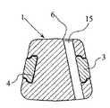
図において観察され得るように、歯部及び歯保持部の組立体は、一旦装着されると、図1〜図5に示されている構造を有しており、それらの図において、互いに他方に連結されている歯保持部1及び歯部2と、側面耳部3及び4とが、認められ得、これらの側面耳部3及び4は、歯保持部1のそれぞれの座部であって、それらの構成は詳述されるであろうものの中へ導入されており、そして、同様に、歯部及び歯保持部を固定するピン用の上部開口5が、観察され得る。
【0006】
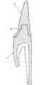
ピンの座部であって、その大体の向きが垂直であるものは、詳細には、一の構造を有しており、この構造においては、僅かに湾曲し且つ、正面図において観察されるであろうように、僅かに傾斜した構成であって、歯保持部の鼻部の側面に実質的に平行な軌道を備えているものが、目立っている。
【0007】
上述の構成は、図11において特に観察されよう。そして、その図11において、ピンの導入を改良すべく意図されている、上部面取り部6の構成も、観察されるべきである。
【0008】
鼻部においてではなく、歯保持部の本体1におけるピンの座部5の構成は、鼻部がより大きい強靭さを得ることを可能にすると共に、組立体の作用領域からピンを移動させ、これにより、ピンは、摩耗から大いに守られる。ピンの座部のほぼ垂直な構成は、取り付け及び取り外しを容易にする一方、その傾斜及び湾曲は、後述されるように、ピンが、耳部のうちの1つの耳部の端部に設けられているアバットメントによって後から捕捉されつつ、ガイド内に保持されるのを、可能にする。同様に、座部の湾曲は、前端壁から穴を移動させ、これにより、破壊を受けやすい脆弱な領域の生成が、避けられる。
【0009】
ピンを着座させ且つ歯部を固定する構成は、座部の長さよりも短い長さを備えているピンを設計することを可能にし、もって、端部は、歯保持部の本体と同じ高さではなく、これは、ピンの摩耗を低減させ且つ衝撃を減少させ、これにより、ピンの劣化だけでなく、現在幾つかの場合において起きている、ピンの損失の可能性もが、避けられる。
【0010】
理解されるであろうように、ピン及びその座部の構成は、記載されてきた好適な変型に応じるであろうが、座部は、湾曲していなくて完全に真直ぐであってもよく、又は、図示されているのとは反対の方向に湾曲していてもよい。同様に、横方向における座部の傾斜も、弱められ得又は除かれ得る。
【0011】
更に、座部は、歯保持部の一方の側又は他方の側に配置されていてもよく、又は、作業が非常に厳しい所での適用では、両方の側に同時に配置されていてもよい。歯保持部内での歯の固定を確実にすべく且つ安定性及び強靭性を高めるべく、第2のピンも、組み込まれ得る。
【0012】
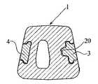
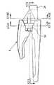
歯部の耳部3及び4は、歯保持部の側面空洞部内に収容されており、それらの側面空洞部は、好適に、僅かに傾斜させられており、それらのうちの1つの側面空洞部が、図6において番号7で指示されている。耳部3及び4は、好適に、歯保持部の側壁部の方向に対応している傾斜、即ち、図において観察され得るように、横断方向の傾斜を有しており、その傾斜により、上縁部は、下縁部よりも、より内部に向けて配設されている。即ち、傾斜は、耳部の、それらの軸線上での或る回転に対応しており、この結果、耳部の上縁部及び下縁部は、異なる鉛直面内にある。所望されるならば、前記傾斜の角度は、ゼロであってもよい。前記空洞部は、異なるタイプの平坦な面、湾曲した面及び他の面を組み合わせた、段付セクションを有している。それは、側部隔壁8及び9を画成し、これらの側部隔壁8及び9は、拡幅されている土台領域12及び13に合流する、それぞれの段部10及び11を有しており、それらの土台領域12及び13は、下部に相当する、番号14によって指示されているもののような湾曲部を好適に有しているが、幅広の傾斜した平面又は真直ぐな段部又は支持領域を広くするための他の適切な形状を形成していてもよい。図6において観察され得るように、ピン用の座部5に対応している空洞部7内に、ピン用の座部の壁が、存在している。同様に、空洞部7の前部15及び後部16には、整合させられている、それぞれの座部17及び18が、存在し、これらの座部17及び18は、歯部における耳部の端部アバットメント20であって、歯保持部を通過するピンを保持するためのものの通過を可能にすべく意図されている、真直ぐなガイドを構成している。通路17及び18によって形成されている溝の長さは、歯保持部と一体となるように嵌合すべく意図されている鼻部即ち突出部19の全長よりも短くてもよく、この様にして、より大きな有効断面が、従って、より大きな強度が、得られる。それにも拘らず、図22に示されているように、歯保持部43は、歯保持部の歯部を受容するための座部44であって、貫通型である、即ち、鼻部即ち後部突出部45の端部に開口しているものを有していてもよい。
【0013】
側面耳部のうちの1つの側面耳部(例えば耳部3)に設けられている、歯部を歯保持部内に案内する側面アバットメント突出部は、図10に示されており、この図10において、上記アバットメント20が、観察され得、そのアバットメント20は、歯保持部の側面座部空洞部内に設けられているガイド内へ導入されている。
【0014】
鼻部19の正確な形状は、歯部と歯保持部との間の実際の連結部の構成に影響を与えることなく、変化させられ得、これは、基本的に、耳部3及び4と、それらの対応する座部と、歯保持部の本体における特別な構成でのピン用の座部とに影響を与える。
【0015】
請求項に示されている本発明の範囲内に留まるであろう種々の変形例が、本発明に導入され得る。従って、例えば、図示されている例においては或る傾斜を有している、耳部の座部は、傾斜を有していなくてもよく、又はベースに垂直であってもよく若しくは湾曲していてもよい。
【0016】
同様に、耳部及びそれらと嵌合する歯保持部の空洞部の内部段付き形状は、2つの異なる面の組合せ(例えば、平坦/平坦又は平坦/湾曲、湾曲/湾曲又は他のタイプ)であってもよい。段付き形状を有しておらず、平らな又は丸い単一の表面を備えている空洞部も、供給され得る。あるいは、空洞部は、直角の形状を有していてもよく、そして、歯保持部内の歯部用ガイドは、一方の側に又は他方の側に又は同時に両方の側に配設されていてもよい。
【0017】
歯保持部内の歯部用ガイドであって、この歯部用ガイドの長さが歯保持部の鼻部の長さの一部のみに好適に限定されているものは、その全体に亘って延在していてもよい、ということも、理解されよう。
【0018】
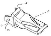
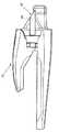
歯部の耳部3及び4は、段付き案内部と湾曲領域とから構成されている。図9において、例えば耳部4について、段付き案内部21及び22と、湾曲端部領域23及び24とが、認識され得る。
【0019】
耳部は、歯保持部の鼻部の側面に平行に僅かに傾斜させられており、歯部の装着の間、歯保持部の側面空洞部内へ嵌入させられる。番号21及び22によって指示されているもののような段付き案内部は、平坦な面の組合せである。図面において番号3によって指示されている、耳部のうちの1つの耳部は、横断方向の孔25であって、ピンの導入を検査し且つ工具の導入によってその取り外しを容易にするためのものを有している。
【0020】
本発明によると、段付き案内部は、歯保持部内への歯の装着を案内すべく且つ組立体を安定にすべく意図されている。耳部のうちの1つの耳部の端部に設けられているアバットメント20は、その後方部分によってピンを保持すべく意図されている。
【0021】
番号23及び24によって指示されているもののような湾曲領域は、平坦な表面と断面とを増大させ、垂直方向の応力をより良く分散させることにより、垂直方向の応力に対して耳部を補強すべく機能する。
【0022】
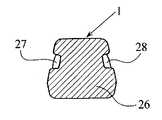
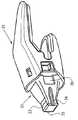
更に、耳部の特定の形状に関して、図17及び図18に示されている変型におけるように、2つのピンの連結をもたらす二重ガイドの場合には、両側に配設されるべきアバットメントが、提供され得、その変型においては、歯保持部の鼻部26は、2つの側面ガイド27及び28であって、それぞれのピン座部29及び30に収容されるそれぞれのピン用のものを有している。
【0023】
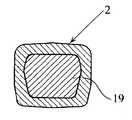
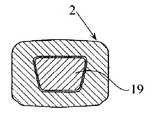
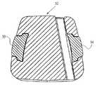
図19は、連結突出部即ち鼻部32を備えている歯保持部31の代替実施形態を示しており、その連結突出部即ち鼻部32は、実質的に正方形又は長方形の角柱形状の端部付加部33を有しており、この端部付加部33は、縦方向リブ34及び35と、貫通型ではない溝36とを有しており、この歯保持部の残りの部分は、特に図6に示されている本発明の特徴に本質的に対応している。
【0024】
図20は、更に別の代替実施形態37を示しており、この代替実施形態37においては、後部突出部即ち鼻部38は、実質的に六角形の断面を有している付加部39であって、真直ぐなリブ40及び41を側部に備えているものを有している。番号42によって指示されている、側面溝のうちの1つの側面溝も、示されており、この歯保持部の残りの部分は、以前に示されている変型に係る本発明に対応している。
【0025】
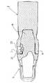
図21は、番号47によって指示されているピン座部を有している歯保持部46を示しており、そのピン座部は、以前に説明されているようにしてほぼ構成されていると共に、この場合、アーチ形の湾曲変型に対応しており、このピン座部の内部に、弾性ブロック50によって支持されている心出し・保持付加部49を搭載しているピン48が、収容されており、そして、心出し・保持付加部49の前部膨張部が、保持手段をガイド溝51内へ部分的に導入している。
【0026】
図23は、歯保持部本体52が歯部の耳部53及び54に連結しているところの変型を示しており、それらの耳部53及び54は、湾曲した断面を有していると共に、歯保持部の受容溝の嵌め合い形状に適応している。
【0027】
図24、図25及び図26に示されているように、ピン48であって、図示されているものにおいては概ねアーチ形であるが、明らかに真直ぐであってもよいものは、弾性ブロック50と金属ブロック55とによって形成されている心出し・保持部材を有しており、この心出し・保持部材は、頂部及び低部に、それぞれの付加的な案内フィン56及び57であって、突出している金属ブロック55よりも幅が狭いものを有しており、ピン48の嵌め合い形状の溝内に収容されている。
【0028】
図27は、歯部58及び歯保持部59の組立体の水平面に沿う断面を示している。前記断面において、ピン60が、認められ得、そのピン60は、弾性ブロック61と金属突出部62とをその中に組み込まれており、それらの構造は、図24〜図26に示されているものに対応している。
【図面の簡単な説明】
【図1】 本発明を組み入れている歯部及び歯保持部の組立体の斜視図である。
【図2】 図1におけるのと同じ組立体の側面図である。
【図3】 図1におけるのと同じ組立体の平面図である。
【図4】 指示されている平面に沿う縦断面を示している。
【図5】 図2に指示されている水平面に沿う断面を示している。
【図6】 本発明の歯保持部の斜視図である。
【図7】 歯保持部の連結端部の平面図である。
【図8】 歯部の斜視図である。
【図9】 同じ歯部の斜視図である。
【図10】 図2に指示されている横断平面に沿う、歯部及び歯保持部の組立体の横断面を示している。
【図11】 図2に指示されている横断平面に沿う、歯部及び歯保持部の組立体の横断面を示している。
【図12】 図2に指示されている横断平面に沿う、歯部及び歯保持部の組立体の横断面を示している。
【図13】 図2に指示されている横断平面に沿う、歯部及び歯保持部の組立体の横断面を示している。
【図14】 図2に指示されている横断平面に沿う、歯部及び歯保持部の組立体の横断面を示している。
【図15】 歯保持部の側面図である。
【図16】 図15に指示されている水平面に沿う歯保持部の断面を示している。
【図17】 図15に指示されている平面に沿う横断面を示している。
【図18】 図15に指示されている平面に沿う横断面を示している。
【図19】 本発明に係る歯保持部の代替実施形態の斜視図を示している。
【図20】 本発明に係る歯保持部の代替実施形態の斜視図を示している。
【図21】 本発明に係る歯保持部の図式縦断面であって、完全に装着されたピンを示しているものを示している。
【図22】 本発明に係る歯保持部の側面図であって、貫通構成における、即ち、歯保持部の鼻部の端部内へ開口している、歯部用の座部即ちガイドを示しているものである。
【図23】 横断方向に湾曲した形状を有している歯部の耳部を伴っている歯保持部の横断面を示している。
【図24】 ピンの斜視図を示している。
【図25】 ピンの正面図を示している。
【図26】 ピンの側面図を示している。
【図27】 歯部及び歯保持部の組立体の縦断面であって、ピンを断面で示しているものを示している。[0001]
The present invention is an improvement introduced to a mechanical connection intended for excavation and can be evaluated based on new and original activities for the above-mentioned purpose-known connection known in the art. It relates to what brings the features.
[0002]
In particular, the couplings of the present invention are applicable to loading and excavating machines in various variants and types, but more broadly they are interchangeable teeth intended to penetrate into the ground to be worked on. It is applicable to all excavators having a working bucket provided with a rim having
[0003]
The present invention is a significant functional improvement in the connection between the tooth and the tooth holding part, which provides greater strength and eliminates possible stress concentrations, while connecting the ears in the tooth. It is intended to provide something that reinforces the area. It is also possible to increase the surface against normal stress, and generally greater penetration is achieved.
[0004]
Similarly, the seat of the pin is arranged in the body of the tooth holding part instead of the usual nose in the tooth part, the configuration is substantially vertical and the tooth holding part said Located on one side of the body and may be straight or slightly curved. When viewed from the front, the seat is usually inclined outwards, because it follows the direction of the side of the body. In addition, the seat has a chamfer at the inlet edge to improve pin mounting, especially during field work.
[0005]
As can be observed in the figures, the tooth and tooth holding assembly, once installed, has the structure shown in FIGS. 1-5, in which each other Connected
[0006]
The seat of the pin, whose general orientation is vertical, has in particular a structure, in which it is slightly curved and can be observed in the front view. As will be apparent, a slightly inclined configuration with a track substantially parallel to the side of the nose portion of the tooth holding portion is conspicuous.
[0007]
The above configuration will be particularly observed in FIG. And in FIG. 11, the configuration of the
[0008]
The configuration of the
[0009]
The configuration in which the pin is seated and the tooth portion is fixed makes it possible to design a pin having a length shorter than the length of the seat portion, so that the end is the same height as the body of the tooth holding portion. Rather, this reduces pin wear and impact, thereby avoiding not only pin degradation, but also the potential pin loss that currently occurs in some cases.
[0010]
As will be appreciated, the configuration of the pin and its seat will depend on the preferred variant that has been described, but the seat may be completely straight without being curved, Alternatively, it may be curved in the opposite direction to that shown. Similarly, the slope of the seat in the lateral direction can also be reduced or eliminated.
[0011]
Furthermore, the seat may be arranged on one side or the other side of the tooth holding part, or it may be arranged on both sides simultaneously for applications where the work is very demanding. A second pin may also be incorporated to ensure the fixation of the teeth within the tooth holding and to increase stability and toughness.
[0012]
The
[0013]
A side abutment protrusion provided on one side ear (for example, the ear 3) of the side ears for guiding the tooth portion into the tooth holding portion is shown in FIG. The
[0014]
The exact shape of the
[0015]
Various modifications may be introduced to the invention that will remain within the scope of the invention as set forth in the claims. Thus, for example, the ear seat, which in the illustrated example has a certain slope, may not have a slope, or may be perpendicular to the base or curved. May be.
[0016]
Similarly, the internal stepped shape of the ears and the cavity of the tooth holding part that fits them can be in two different surface combinations (eg flat / flat or flat / curved, curved / curved or other types). There may be. Cavities that do not have a stepped shape and that have a flat or round single surface can also be provided. Alternatively, the cavity may have a right-angle shape and the tooth guide in the tooth holding part may be arranged on one side or on the other side or on both sides simultaneously. Good.
[0017]
A tooth guide in the tooth holding portion, the length of which is preferably limited to only a part of the length of the nose of the tooth holding portion, extends over the entire length. It will be understood that it may exist.
[0018]
The
[0019]
The ear portion is slightly inclined parallel to the side surface of the nose portion of the tooth holding portion, and is fitted into the side cavity portion of the tooth holding portion during the mounting of the tooth portion. Stepped guides such as those indicated by the
[0020]
According to the present invention, the stepped guide is intended to guide the mounting of the teeth in the tooth holding part and to stabilize the assembly. The
[0021]
Curved areas such as those indicated by
[0022]
Furthermore, with regard to the specific shape of the ear, as in the variant shown in FIGS. 17 and 18, in the case of a double guide providing a connection of two pins, the abutment to be arranged on both sides is In its variant, the
[0023]
FIG. 19 shows an alternative embodiment of the
[0024]
FIG. 20 shows yet another
[0025]
FIG. 21 shows a
[0026]
FIG. 23 shows a variation where the
[0027]
As shown in FIGS. 24, 25 and 26, the
[0028]
FIG. 27 shows a cross section along the horizontal plane of the assembly of the
[Brief description of the drawings]
FIG. 1 is a perspective view of a tooth and tooth holding assembly incorporating the present invention.
FIG. 2 is a side view of the same assembly as in FIG.
3 is a plan view of the same assembly as in FIG. 1. FIG.
FIG. 4 shows a longitudinal section along the indicated plane.
FIG. 5 shows a section along the horizontal plane indicated in FIG.
FIG. 6 is a perspective view of a tooth holding portion of the present invention.
FIG. 7 is a plan view of a connecting end portion of a tooth holding portion.
FIG. 8 is a perspective view of a tooth portion.
FIG. 9 is a perspective view of the same tooth portion.
FIG. 10 shows a cross section of the tooth and tooth holding assembly along the transverse plane indicated in FIG.
FIG. 11 shows a cross section of the tooth and tooth holding assembly along the transverse plane indicated in FIG.
12 shows a cross section of the tooth and tooth holding assembly along the transverse plane indicated in FIG. 2;
FIG. 13 shows a cross section of the tooth and tooth holding assembly along the transverse plane indicated in FIG.
FIG. 14 shows a cross section of the tooth and tooth holding assembly along the transverse plane indicated in FIG.
FIG. 15 is a side view of a tooth holding part.
FIG. 16 shows a cross section of the tooth holding part along the horizontal plane indicated in FIG.
FIG. 17 shows a cross section along the plane indicated in FIG.
FIG. 18 shows a cross section along the plane indicated in FIG.
FIG. 19 shows a perspective view of an alternative embodiment of a tooth holder according to the present invention.
FIG. 20 shows a perspective view of an alternative embodiment of a tooth holding part according to the invention.
FIG. 21 shows a schematic longitudinal section of a tooth holding part according to the present invention showing a fully mounted pin.
FIG. 22 is a side view of a tooth holding part according to the invention, showing a seat or guide for the tooth part in a penetrating configuration, ie opening into the end of the nose part of the tooth holding part; It is what.
FIG. 23 shows a cross-section of a tooth holding part with a tooth ear having a transversely curved shape.
FIG. 24 shows a perspective view of the pin.
FIG. 25 shows a front view of the pin.
FIG. 26 shows a side view of the pin.
FIG. 27 shows a longitudinal section of an assembly of a tooth portion and a tooth holding portion, showing a pin in cross section.
Claims (21)
Translated fromJapanese前記耳部(3,4,53,54)が、左右の耳部におけるそれぞれの上端部同士の間の距離が左右の耳部におけるそれぞれの下端部同士の間の距離よりも短くなるようにして、互いに傾斜させられている、
ことを特徴とする歯部。A tooth portion (2,58) connected to a tooth holding portion (1,43,46,52,59) of an excavator, and receiving a protrusion (19,26,38,45) of the tooth holding portion and the cavity portion, is received in a housing (7) a corresponding tooth holder, in which are provided a ear (3,4,53,54) protruding on each side ofsaid cavity ,
The ears (3, 4, 53, 54) are such that the distancebetween theupper ends of theleft and right ears is shorter than the distancebetween thelower ends of the left and right ears.Are inclined toeach other ,
The tooth part characterized by this.
各ハウジング(7)の側部内面であって、耳部(3,4,53,54)の内側面に面すべく意図されているものが、左右のハウジングにおけるそれぞれの上端部同士の間の横断距離が左右のハウジングにおけるそれぞれの下端部同士の間の横断距離よりも短くなるようにして、互いに傾斜させられている、
ことを特徴とする歯保持部。A tooth holding portion (1, 43, 46, 52, 59) connected to the excavator, and a protrusion (19, 26, 38, 45) disposed in the cavity of the tooth portion (2, 58); in those and a housing (7) which is arranged to receive the ear portion (3,4,53,54) protruding teeth, on each side ofthe protrusion,
A side inner surface of each housing (7) that is intended to face the inner surface of the ear (3, 4, 53, 54) isbetween the upper ends of theleft andright housings. The transverse distance is inclined with respect toeach other such that the transverse distance is shorter than the transverse distancebetween the lower ends of the left and right housings ,
A tooth holding part.
Applications Claiming Priority (3)
| Application Number | Priority Date | Filing Date | Title |
|---|---|---|---|
| ES9902161 | 1999-10-01 | ||
| ES009902161AES2158805B1 (en) | 1999-10-01 | 1999-10-01 | IMPROVEMENTS IN THE COUPLINGS FOR MACHINE TEETH FOR GROUND MOVEMENT. |
| PCT/ES2000/000364WO2001025550A1 (en) | 1999-10-01 | 2000-09-28 | Improvements in the assemblies of teeth of earth moving machines |
Publications (2)
| Publication Number | Publication Date |
|---|---|
| JP2003511587A JP2003511587A (en) | 2003-03-25 |
| JP3785437B2true JP3785437B2 (en) | 2006-06-14 |
Family
ID=8310106
Family Applications (1)
| Application Number | Title | Priority Date | Filing Date |
|---|---|---|---|
| JP2001528273AExpired - LifetimeJP3785437B2 (en) | 1999-10-01 | 2000-09-28 | Improvements in excavator tooth assembly. |
Country Status (15)
| Country | Link |
|---|---|
| US (2) | US6865828B1 (en) |
| EP (2) | EP1331314B1 (en) |
| JP (1) | JP3785437B2 (en) |
| KR (2) | KR100613232B1 (en) |
| CN (2) | CN1168878C (en) |
| AR (1) | AR025716A1 (en) |
| AT (2) | ATE275222T1 (en) |
| AU (1) | AU770906B2 (en) |
| BR (1) | BR0014435B1 (en) |
| CA (1) | CA2385789C (en) |
| DE (2) | DE60013483T2 (en) |
| ES (3) | ES2158805B1 (en) |
| MY (2) | MY126608A (en) |
| WO (1) | WO2001025550A1 (en) |
| ZA (1) | ZA200202323B (en) |
Families Citing this family (89)
| Publication number | Priority date | Publication date | Assignee | Title |
|---|---|---|---|---|
| ES2146541B1 (en)* | 1998-06-08 | 2001-04-01 | Metalogenia Sa | DEVICE FOR THE COUPLING OF EXCAVATOR TEETH. |
| SE0203856L (en)* | 2002-12-23 | 2004-02-10 | Combi Wear Parts Ab | Wear part system for detachable mounting of wear parts to a soil preparation machine tool |
| ES2222090B1 (en)* | 2003-05-29 | 2007-07-01 | Metalogenia Patentes, S.L. | TOOTH, PORTABLE, AND SET OF TOOTH AND PORTABLE, TO MACHINE TO MOVE MATERIALS SUCH AS EARTH AND STONES. |
| SE524301C2 (en)* | 2003-07-11 | 2004-07-20 | Combi Wear Parts Ab | Toothed system is provided for tool for ground working machine and involves holder part fitted to tool, to which toothed part is releasably arranged formed as exchangeable or replaceable part in itself provided for ground working |
| MXPA06006398A (en)* | 2003-12-05 | 2006-08-23 | Metalogenia Sa | Wear assembly and components thereof, which is intended for machines that are used to move materials such as earth and stones. |
| USD552632S1 (en)* | 2004-02-10 | 2007-10-09 | Italricambi Srl | Tooth assembly for buckets |
| ITUD20040021A1 (en)* | 2004-02-10 | 2004-05-10 | Italricambi Srl | TOOTH FOR EXCAVATOR BUCKETS OR SIMILAR |
| USD552631S1 (en)* | 2004-02-10 | 2007-10-09 | Italricambi Srl | Tooth assembly for buckets |
| PT1741842E (en)* | 2004-03-30 | 2010-12-07 | Metalogenia Sa | Device for removably fixing two mechanical parts to one another |
| EP1778924A4 (en)* | 2004-08-02 | 2011-07-06 | Bradken Operations Pty Ltd | Tooth and adaptor assembly |
| JOP20190303A1 (en)* | 2006-02-17 | 2017-06-16 | Esco Group Llc | Wear assembly |
| PL3263776T3 (en)* | 2006-03-30 | 2022-01-17 | Esco Group Llc | Wear assembly |
| CN101558206B (en)* | 2006-09-01 | 2011-12-14 | 麦塔洛吉尼亚股份有限公司 | Prong and fitting for a dredging machine |
| US8061064B2 (en) | 2007-05-10 | 2011-11-22 | Esco Corporation | Wear assembly for excavating equipment |
| PL2865814T3 (en)* | 2007-05-10 | 2019-05-31 | Esco Group Llc | Wear assembly for excavating equipment |
| US8069593B2 (en)* | 2008-01-17 | 2011-12-06 | Caterpillar Inc. | Excavator bucket top assembly |
| US20090277050A1 (en)* | 2008-05-06 | 2009-11-12 | Esco Corporation | Wear Assembly For Excavating Equipment |
| CN101768992B (en)* | 2008-12-30 | 2011-12-21 | 宁波浙东精密铸造有限公司 | Excavating tooth component, tooth holder and bucket teeth |
| WO2010089423A1 (en)* | 2009-02-06 | 2010-08-12 | Metalogenia, S.A. | Coupling system for use between a wear element and an adaptor for excavator machines and similar, and components thereof |
| US7980011B2 (en)* | 2009-03-23 | 2011-07-19 | Black Cat Blades Ltd. | Fully stabilized excavator tooth attachment |
| US9359744B2 (en)* | 2009-08-05 | 2016-06-07 | H&L Tooth Company | Multipiece wear assembly |
| WO2011016858A1 (en)* | 2009-08-05 | 2011-02-10 | H&L Tooth Company | Tooth assembly and related method for releasably coupling a tooth to an adapter |
| BR112012011448B1 (en)* | 2009-10-30 | 2019-11-05 | Esco Corp | excavation equipment wear element and assembly |
| EP2507437A1 (en)* | 2009-12-11 | 2012-10-10 | CQMS Pty Ltd | A wear member assembly |
| WO2011088511A1 (en) | 2010-01-20 | 2011-07-28 | Bradken Resources Pty Limited | Excavation tooth assembly |
| US9562347B2 (en)* | 2010-08-04 | 2017-02-07 | H&L Tooth Company | Multipiece wear assembly |
| US20120297649A1 (en)* | 2011-05-27 | 2012-11-29 | Caterpillar, Inc. | Ground engaging tool tooth tip |
| USD706311S1 (en) | 2011-10-07 | 2014-06-03 | Caterpillar, Inc. | Tip for a ground engaging machine implement |
| USD706307S1 (en) | 2011-10-07 | 2014-06-03 | Caterpillar, Inc. | Adapter for a ground engaging machine implement |
| US8943717B2 (en) | 2011-10-08 | 2015-02-03 | Caterpillar Inc. | Implement tooth assembly with tip and adapter |
| USD706840S1 (en) | 2011-10-07 | 2014-06-10 | Caterpillar, Inc. | Tip for a ground engaging machine implement |
| USD707264S1 (en) | 2011-10-07 | 2014-06-17 | Caterpillar Inc. | Adapter for a ground engaging machine implement |
| USD706312S1 (en) | 2011-10-07 | 2014-06-03 | Caterpiller, Inc. | Tip for a ground engaging machine implement |
| US9062436B2 (en) | 2011-10-07 | 2015-06-23 | Caterpillar Inc. | Implement tooth assembly with tip and adapter |
| USD706839S1 (en) | 2011-10-07 | 2014-06-10 | Caterpillar, Inc. | Tip for a ground engaging machine implement |
| USD727980S1 (en) | 2014-04-08 | 2015-04-28 | Caterpillar Inc. | Tip for a ground engaging machine implement |
| USD707263S1 (en) | 2011-10-07 | 2014-06-17 | Caterpillar, Inc. | Tip for a ground engaging machine implement |
| US9057177B2 (en) | 2011-10-08 | 2015-06-16 | Caterpillar Inc. | Implement tooth assembly with tip and adapter |
| US8943716B2 (en) | 2011-10-10 | 2015-02-03 | Caterpillar Inc. | Implement tooth assembly with tip and adapter |
| FR2983880B1 (en)* | 2011-12-08 | 2014-11-21 | Afe Metal | MECHANICAL SYSTEM COMPRISING A WEAR PIECE AND A SUPPORT, AND BUCKET COMPRISING AT LEAST ONE SUCH A MECHANICAL SYSTEM |
| JP6132464B2 (en)* | 2012-01-12 | 2017-05-24 | 株式会社技研製作所 | holder |
| CN102619253B (en)* | 2012-04-11 | 2015-05-06 | 宁波市鄞州精铸五金厂 | Bucket tooth of excavator |
| AU2013204898B2 (en)* | 2013-04-12 | 2016-11-03 | Bradken Resources Pty Limited | Excavation Tooth Assembly |
| EP2829664A1 (en)* | 2013-07-22 | 2015-01-28 | Metalogenia Research & Technologies S.L. | Male and female parts for a wear assembly of an earth-moving machine's bucket |
| USD728637S1 (en) | 2013-08-01 | 2015-05-05 | Caterpillar Inc. | Tip for a ground engaging machine implement |
| USD728635S1 (en) | 2013-08-01 | 2015-05-05 | Caterpillar Inc. | Coupler for a ground engaging machine implement |
| US9273448B2 (en)* | 2013-08-01 | 2016-03-01 | Caterpillar Inc. | Ground engaging tool assembly |
| USD728636S1 (en) | 2013-08-01 | 2015-05-05 | Caterpillar Inc. | Coupler and tip for a ground engaging machine implement |
| USD774108S1 (en) | 2015-08-12 | 2016-12-13 | Caterpillar Inc. | Tip for a ground engaging machine implement |
| USD774566S1 (en) | 2015-08-12 | 2016-12-20 | Caterpillar Inc. | Tip for a ground engaging machine implement |
| USD774565S1 (en) | 2015-08-12 | 2016-12-20 | Caterpillar Inc. | Tip for a ground engaging machine implement |
| USD775242S1 (en) | 2015-08-12 | 2016-12-27 | Caterpillar Inc. | Tip for a ground engaging machine implement |
| USD775673S1 (en) | 2015-08-12 | 2017-01-03 | Caterpillar Inc. | Tip for a ground engaging machine implement |
| USD775240S1 (en) | 2015-08-12 | 2016-12-27 | Caterpillar Inc. | Tip for a ground engaging machine implement |
| USD774564S1 (en) | 2015-08-12 | 2016-12-20 | Caterpillar Inc. | Tip for a ground engaging machine implement |
| USD775241S1 (en) | 2015-08-12 | 2016-12-27 | Caterpillar Inc. | Tip for a ground engaging machine implement |
| USD774109S1 (en) | 2015-08-12 | 2016-12-13 | Caterpillar Inc. | Tip for a ground engaging machine implement |
| USD775243S1 (en) | 2015-08-12 | 2016-12-27 | Caterpillar Inc. | Tip for a ground engaging machine implement |
| USD774110S1 (en) | 2015-08-12 | 2016-12-13 | Caterpillar Inc. | Tip for a ground engaging machine implement |
| USD774567S1 (en) | 2015-08-12 | 2016-12-20 | Caterpillar Inc. | Tip for a ground engaging machine implement |
| CN105714075B (en)* | 2016-01-30 | 2019-05-28 | 李令禹 | A kind of excavator-type shovel clamshell excavator seperated bucket tooth and its manufacturing method |
| US10508418B2 (en) | 2016-05-13 | 2019-12-17 | Hensley Industries, Inc. | Stabilizing features in a wear member assembly |
| WO2017209898A1 (en)* | 2016-06-03 | 2017-12-07 | H&L Tooth Company | Multipiece wear assembly |
| CN109415885A (en)* | 2016-07-06 | 2019-03-01 | 成矿研究科技有限公司 | The abrasion of tool for earth mover or protection system and corresponding pin |
| USD806758S1 (en) | 2016-12-15 | 2018-01-02 | Caterpillar Inc. | Tip for a ground engaging machine implement |
| USD806142S1 (en) | 2016-12-15 | 2017-12-26 | Caterpillar Inc. | Adapter for a ground engaging machine implement |
| USD806139S1 (en) | 2016-12-15 | 2017-12-26 | Caterpillar Inc. | Adapter for a ground engaging machine implement |
| USD805112S1 (en) | 2016-12-15 | 2017-12-12 | Caterpillar Inc. | Tip for a ground engaging machine implement |
| USD803898S1 (en) | 2016-12-15 | 2017-11-28 | Caterpillar Inc. | Tip for a ground engaging machine implement |
| USD806141S1 (en) | 2016-12-15 | 2017-12-26 | Caterpillar Inc. | Adapter for a ground engaging machine implement |
| USD803899S1 (en) | 2016-12-15 | 2017-11-28 | Caterpillar Inc. | Tip for a ground engaging machine implement |
| USD803900S1 (en) | 2016-12-15 | 2017-11-28 | Caterpillar Inc. | Tip for a ground engaging machine implement |
| USD806140S1 (en) | 2016-12-15 | 2017-12-26 | Caterpillar Inc. | Adapter for a ground engaging machine implement |
| USD803274S1 (en) | 2016-12-15 | 2017-11-21 | Caterpillar Inc. | Tip for a ground engaging machine implement |
| USD803901S1 (en) | 2016-12-15 | 2017-11-28 | Caterpillar Inc. | Tip for a ground engaging machine implement |
| USD803897S1 (en) | 2016-12-15 | 2017-11-28 | Caterpillar Inc. | Tip for a ground engaging machine implement |
| USD806759S1 (en) | 2016-12-15 | 2018-01-02 | Caterpillar Inc. | Tip for a ground engaging machine implement |
| USD803902S1 (en) | 2016-12-15 | 2017-11-28 | Caterpillar Inc. | Tip for a ground engaging machine implement |
| USD803275S1 (en) | 2016-12-15 | 2017-11-21 | Caterpillar Inc. | Tip for a ground engaging machine implement |
| USD805562S1 (en) | 2016-12-15 | 2017-12-19 | Caterpillar Inc. | Adapter for a ground engaging machine implement |
| USD840441S1 (en) | 2016-12-15 | 2019-02-12 | Caterpillar Inc. | Adapter for a ground engaging machine implement |
| JP6282765B2 (en)* | 2017-02-01 | 2018-02-21 | 株式会社技研製作所 | Connecting structure and excavation claw |
| USD832310S1 (en) | 2017-08-30 | 2018-10-30 | Caterpillar Inc. | Adapter for a ground engaging machine implement |
| USD918965S1 (en) | 2018-06-19 | 2021-05-11 | Hensley Industries, Inc. | Ground engaging wear member |
| USD905765S1 (en) | 2019-03-07 | 2020-12-22 | Caterpillar Inc. | Adapter for a ground engaging machine implement |
| USD888785S1 (en) | 2019-03-07 | 2020-06-30 | Caterpillar Inc. | Adapter for a ground engaging machine implement |
| JP7160777B2 (en)* | 2019-09-13 | 2022-10-25 | 株式会社小松製作所 | Bucket tooth mounting structure and bucket tooth |
| USD945499S1 (en) | 2020-11-18 | 2022-03-08 | Caterpillar Inc. | Adapter for a ground engaging machine implement |
| USD945498S1 (en) | 2020-11-18 | 2022-03-08 | Caterpillar Inc. | Adapter for a ground engaging machine implement |
Family Cites Families (45)
| Publication number | Priority date | Publication date | Assignee | Title |
|---|---|---|---|---|
| US247148A (en)* | 1881-09-20 | Chaeles anderson | ||
| US1775984A (en)* | 1928-10-23 | 1930-09-16 | Electric Steel Foundry Co | Dipper-tooth structure |
| US2050014A (en) | 1934-12-10 | 1936-08-04 | American Manganese Steel Co | Box type cap for excavating teeth |
| US2483032A (en)* | 1945-06-06 | 1949-09-27 | Electric Steel Foundry | Excavating tooth |
| US2435846A (en) | 1946-01-07 | 1948-02-10 | Elmer E Robertson | Tooth for power shovels |
| US2921391A (en) | 1955-07-06 | 1960-01-19 | American Steel Foundries | Dipper tooth assembly |
| US3117386A (en) | 1961-03-07 | 1964-01-14 | Ferwerda Ray | Tooth arrangement for earth digging apparatus |
| US3496658A (en) | 1967-12-22 | 1970-02-24 | Esco Corp | Excavating tooth components |
| US3574962A (en) | 1968-12-11 | 1971-04-13 | Caterpillar Tractor Co | Earthworking tip mounted for limited pivotal movement |
| US3520224A (en) | 1969-02-12 | 1970-07-14 | Hensley Equipment Co Inc | Retaining pin |
| US3839805A (en) | 1972-09-29 | 1974-10-08 | Caterpillar Tractor Co | Open side ground engaging tip |
| BR6308410D0 (en) | 1972-10-31 | 1974-09-05 | Poclain Sa | REPLACEMENT TOOTH FOR PUBLIC WORKS INSTRUMENT, ADMITTING A PRIVATE KEY |
| US3919792A (en) | 1974-11-25 | 1975-11-18 | Esco Corp | Excavating tooth assembly |
| FR2377488A1 (en) | 1977-01-14 | 1978-08-11 | Poncin Andre | IMPROVEMENTS ON MECHANICAL SHOVEL BUCKETS TEETH |
| DE2713227C2 (en) | 1977-03-25 | 1983-08-04 | O & K Orenstein & Koppel Ag, 1000 Berlin | Detachable fastening of an excavator tooth provided with a sleeve at the rear on a tooth holder engaging in the sleeve |
| US4404760A (en)* | 1980-04-28 | 1983-09-20 | Esco Corporation | Excavating tooth |
| SE445125B (en) | 1981-03-26 | 1986-06-02 | Bofors Ab | SOIL WORKING MACHINERY SYSTEM |
| SE450504B (en) | 1983-07-26 | 1987-06-29 | Bofors Wear Parts Ab | WRADING SYSTEM FOR EQUIPMENT TOOLS |
| US4727663A (en) | 1985-10-24 | 1988-03-01 | Esco Corporation | Excavating tooth having a lock including a basket spring |
| US4761900A (en) | 1986-12-04 | 1988-08-09 | Esco Corporation | Excavating tooth assembly |
| US4799823A (en) | 1987-06-18 | 1989-01-24 | Williams Thomas D | Plow with readily replaceable wear parts especially adapted for use in a vibratory cable laying machine |
| SU1588866A1 (en)* | 1987-08-11 | 1990-08-30 | Институт горного дела им.А.А.Скочинского | Working tool |
| US4903420A (en)* | 1988-10-20 | 1990-02-27 | Esco Corporation | Mining tooth point |
| US5068986A (en) | 1990-08-30 | 1991-12-03 | Esco Corporation | Excavating tooth point particularly suited for large dragline buckets |
| US5088214A (en) | 1991-01-17 | 1992-02-18 | Esco Corporation | Excavator wear edge |
| AU1981392A (en)* | 1991-05-07 | 1992-12-21 | Magotteaux International S.A. | Tooth/tooth holder assembly for milling heads |
| AU672771B2 (en) | 1991-12-20 | 1996-10-17 | Esco Corporation | Attachments for excavating bucket |
| US5469648A (en) | 1993-02-02 | 1995-11-28 | Esco Corporation | Excavating tooth |
| US5386653A (en)* | 1993-06-01 | 1995-02-07 | Caterpillar Inc. | Tooth to adapter interface |
| DE59400217D1 (en) | 1993-08-30 | 1996-05-23 | Baz Service Ag | Excavator tooth |
| US5456029A (en) | 1993-11-01 | 1995-10-10 | Caterpillar Inc. | Tooth to adapter coupler |
| SE504157C2 (en) | 1994-03-21 | 1996-11-25 | Componenta Wear Parts Ab | The tooth arrangement; joining with a sprint |
| US5423138A (en)* | 1994-04-04 | 1995-06-13 | Caterpillar, Inc. | Tip to adapter interface |
| US5502905A (en) | 1994-04-26 | 1996-04-02 | Caterpillar Inc. | Tooth having abrasion resistant material applied thereto |
| US5617655A (en) | 1995-03-22 | 1997-04-08 | H&L Tooth Company | Securement pin for earth excavation teeth |
| US5561925A (en)* | 1995-07-25 | 1996-10-08 | Caterpillar Inc. | Tooth assembly and retaining mechanism |
| US5653048A (en) | 1995-11-06 | 1997-08-05 | Esco Corporation | Wear assembly for a digging edge of an excavator |
| ES2138311T3 (en)* | 1996-07-01 | 2000-01-01 | Metalogenia Sa | COUPLING UNION FOR TEETH OF EXCAVATOR MACHINES. |
| US5765301A (en) | 1996-08-05 | 1998-06-16 | H&L Tooth Company | Retention apparatus for a ground engaging tool |
| US6030143A (en) | 1997-12-18 | 2000-02-29 | Esco Corporation | Locking pin for excavating equipment |
| US5987787A (en) | 1998-02-11 | 1999-11-23 | Wright Equipment Company (Proprietary) Limited | Ground engaging tool components |
| ES2146174B1 (en)* | 1998-07-03 | 2002-01-16 | Metalogenia Sa | COUPLING FOR EXCAVATOR AND SIMILAR TEETH. |
| US6047487A (en) | 1998-07-17 | 2000-04-11 | H&L Tooth Co. | Multipiece excavating tooth assembly |
| US6477796B1 (en)* | 2000-07-06 | 2002-11-12 | Caterpillar Inc | Tooth assembly for implements |
| US6240663B1 (en) | 2000-09-18 | 2001-06-05 | G. H. Hensley Industries, Incorporated | Streamlined resilient connection system for attaching a wear member to an excavating lip structure |
- 1999
- 1999-10-01ESES009902161Apatent/ES2158805B1/ennot_activeExpired - Fee Related
- 2000
- 2000-09-19ARARP000104914Apatent/AR025716A1/enactiveIP Right Grant
- 2000-09-23MYMYPI20004454patent/MY126608A/enunknown
- 2000-09-23MYMYPI20051700Apatent/MY139648A/enunknown
- 2000-09-28CACA002385789Apatent/CA2385789C/ennot_activeExpired - Lifetime
- 2000-09-28WOPCT/ES2000/000364patent/WO2001025550A1/enactiveIP Right Grant
- 2000-09-28KRKR1020037010661Apatent/KR100613232B1/ennot_activeExpired - Lifetime
- 2000-09-28DEDE60013483Tpatent/DE60013483T2/ennot_activeExpired - Lifetime
- 2000-09-28USUS10/089,596patent/US6865828B1/ennot_activeExpired - Lifetime
- 2000-09-28CNCNB008133433Apatent/CN1168878C/ennot_activeExpired - Lifetime
- 2000-09-28BRBRPI0014435-5Apatent/BR0014435B1/ennot_activeIP Right Cessation
- 2000-09-28JPJP2001528273Apatent/JP3785437B2/ennot_activeExpired - Lifetime
- 2000-09-28ESES00966170Tpatent/ES2226925T3/ennot_activeExpired - Lifetime
- 2000-09-28ATAT00966170Tpatent/ATE275222T1/ennot_activeIP Right Cessation
- 2000-09-28AUAU76651/00Apatent/AU770906B2/ennot_activeExpired
- 2000-09-28EPEP03001310Apatent/EP1331314B1/ennot_activeExpired - Lifetime
- 2000-09-28CNCNB2004100485973Apatent/CN100355994C/ennot_activeExpired - Lifetime
- 2000-09-28EPEP00966170Apatent/EP1239088B1/ennot_activeExpired - Lifetime
- 2000-09-28ESES03001310Tpatent/ES2305357T3/ennot_activeExpired - Lifetime
- 2000-09-28KRKR1020027003958Apatent/KR100613231B1/ennot_activeExpired - Lifetime
- 2000-09-28ATAT03001310Tpatent/ATE393269T1/ennot_activeIP Right Cessation
- 2000-09-28DEDE60038706Tpatent/DE60038706T2/ennot_activeExpired - Lifetime
- 2002
- 2002-03-22ZAZA200202323Apatent/ZA200202323B/enunknown
- 2004
- 2004-04-13USUS10/822,809patent/US20040244235A1/ennot_activeAbandoned
Also Published As
Similar Documents
| Publication | Publication Date | Title |
|---|---|---|
| JP3785437B2 (en) | Improvements in excavator tooth assembly. | |
| JP3749438B2 (en) | Teeth, tooth mounting device and tooth system provided with them | |
| US6745503B1 (en) | Device for the coupling of excavator teeth | |
| US3444633A (en) | Two-part excavating tooth | |
| ES2867551T3 (en) | Wear set | |
| US20060236567A1 (en) | Insert for locking mechanism for ground engaging tools | |
| CA2163164C (en) | Excavator tooth | |
| JP2006525450A (en) | Wear assembly for excavator edge | |
| WO1999016982A1 (en) | Excavating tooth assembly | |
| US20050055853A1 (en) | Mechanically attached tip assembly | |
| JP2007009631A (en) | Bucket | |
| AU2002300640B2 (en) | Improvements in the Assemblies of Teeth of Earth Moving Machines | |
| JP2545354Y2 (en) | Drilling blade holding structure | |
| AU778981B2 (en) | Locking pin for ground engaging tool components | |
| FI90578C (en) | Excavator tooth replacement blade | |
| AU2002324020B2 (en) | Device for the Coupling of Excavator Teeth | |
| MXPA00011866A (en) | Device for the coupling of excavator teeth |
Legal Events
| Date | Code | Title | Description |
|---|---|---|---|
| A131 | Notification of reasons for refusal | Free format text:JAPANESE INTERMEDIATE CODE: A131 Effective date:20050405 | |
| RD02 | Notification of acceptance of power of attorney | Free format text:JAPANESE INTERMEDIATE CODE: A7422 Effective date:20050701 | |
| A131 | Notification of reasons for refusal | Free format text:JAPANESE INTERMEDIATE CODE: A131 Effective date:20050809 | |
| A521 | Request for written amendment filed | Free format text:JAPANESE INTERMEDIATE CODE: A523 Effective date:20051027 | |
| TRDD | Decision of grant or rejection written | ||
| A01 | Written decision to grant a patent or to grant a registration (utility model) | Free format text:JAPANESE INTERMEDIATE CODE: A01 Effective date:20060110 | |
| A711 | Notification of change in applicant | Free format text:JAPANESE INTERMEDIATE CODE: A711 Effective date:20060208 | |
| A61 | First payment of annual fees (during grant procedure) | Free format text:JAPANESE INTERMEDIATE CODE: A61 Effective date:20060208 | |
| A521 | Request for written amendment filed | Free format text:JAPANESE INTERMEDIATE CODE: A821 Effective date:20060208 | |
| R150 | Certificate of patent or registration of utility model | Ref document number:3785437 Country of ref document:JP Free format text:JAPANESE INTERMEDIATE CODE: R150 Free format text:JAPANESE INTERMEDIATE CODE: R150 | |
| FPAY | Renewal fee payment (event date is renewal date of database) | Free format text:PAYMENT UNTIL: 20090331 Year of fee payment:3 | |
| FPAY | Renewal fee payment (event date is renewal date of database) | Free format text:PAYMENT UNTIL: 20100331 Year of fee payment:4 | |
| R250 | Receipt of annual fees | Free format text:JAPANESE INTERMEDIATE CODE: R250 | |
| FPAY | Renewal fee payment (event date is renewal date of database) | Free format text:PAYMENT UNTIL: 20110331 Year of fee payment:5 | |
| R250 | Receipt of annual fees | Free format text:JAPANESE INTERMEDIATE CODE: R250 | |
| R250 | Receipt of annual fees | Free format text:JAPANESE INTERMEDIATE CODE: R250 | |
| FPAY | Renewal fee payment (event date is renewal date of database) | Free format text:PAYMENT UNTIL: 20120331 Year of fee payment:6 | |
| FPAY | Renewal fee payment (event date is renewal date of database) | Free format text:PAYMENT UNTIL: 20130331 Year of fee payment:7 | |
| R250 | Receipt of annual fees | Free format text:JAPANESE INTERMEDIATE CODE: R250 | |
| FPAY | Renewal fee payment (event date is renewal date of database) | Free format text:PAYMENT UNTIL: 20130331 Year of fee payment:7 | |
| FPAY | Renewal fee payment (event date is renewal date of database) | Free format text:PAYMENT UNTIL: 20140331 Year of fee payment:8 | |
| R250 | Receipt of annual fees | Free format text:JAPANESE INTERMEDIATE CODE: R250 | |
| R250 | Receipt of annual fees | Free format text:JAPANESE INTERMEDIATE CODE: R250 | |
| R250 | Receipt of annual fees | Free format text:JAPANESE INTERMEDIATE CODE: R250 | |
| R250 | Receipt of annual fees | Free format text:JAPANESE INTERMEDIATE CODE: R250 | |
| R250 | Receipt of annual fees | Free format text:JAPANESE INTERMEDIATE CODE: R250 | |
| R250 | Receipt of annual fees | Free format text:JAPANESE INTERMEDIATE CODE: R250 | |
| R250 | Receipt of annual fees | Free format text:JAPANESE INTERMEDIATE CODE: R250 | |
| R250 | Receipt of annual fees | Free format text:JAPANESE INTERMEDIATE CODE: R250 |