JP3785247B2 - Semiconductor manufacturing equipment - Google Patents
Semiconductor manufacturing equipmentDownload PDFInfo
- Publication number
- JP3785247B2 JP3785247B2JP17144197AJP17144197AJP3785247B2JP 3785247 B2JP3785247 B2JP 3785247B2JP 17144197 AJP17144197 AJP 17144197AJP 17144197 AJP17144197 AJP 17144197AJP 3785247 B2JP3785247 B2JP 3785247B2
- Authority
- JP
- Japan
- Prior art keywords
- purge gas
- seal cap
- furnace
- end opening
- port
- Prior art date
- Legal status (The legal status is an assumption and is not a legal conclusion. Google has not performed a legal analysis and makes no representation as to the accuracy of the status listed.)
- Expired - Fee Related
Links
Images


Landscapes
- Chemical Vapour Deposition (AREA)
Description
Translated fromJapanese【0001】
【発明の属する技術分野】
本発明は、半導体製造工程のうち前処理工程に属する拡散・CVD(化学気相成長)を行う半導体製造装置に係り、特に炉口部構造に関する。
【0002】
【従来の技術】
図7により縦型炉を備えた半導体製造装置の概略を説明する。
【0003】
この半導体製造装置は、筐体1の内部上方に、ヒーター2の内部に反応管3を備えている。反応管3は、炉口(本図では見えず)を下向きにして鉛直に立てられたもので、反応管3の下には炉口部材(インレットフランジ)(本図では見えず)がある。その下方にはボートエレベータ(昇降機構)4が設けられている。ボートエレベータ4の昇降スライダ5には、炉口部材を閉塞するシールキャップ6が設けられ、シールキャップ6上に配した設置台7には、石英又はSiC製のボート8が設置されている。ボート8には、被処理物であるウェーハ10が水平姿勢で多段に載置される。
【0004】
ボートエレベータ4の側方にはウェーハ移載機11が設置され、該ウェーハ移載機11の更に側方に、カセットストッカ13が設置されている。カセットストッカ13は、ウェーハカセット14を所要数格納できるもので、ウェーハ10の半導体装置への搬入、搬出はウェーハカセット14に装填した状態で行われる。
【0005】
ウェーハ10の処理を行う場合は、ボートエレベータ4を上昇側に駆動して、ウェーハ10の載置されているボート8を反応管3に挿入する。その際、同時に上昇するシールキャップ6が最後に炉口部材を閉塞することで、処理の開始が可能となる。所定の処理が完了したら、ボートエレベータ4を下降側に駆動する。そうすると、シールキャップ6が下降して炉口が開放する共に、ボート8が反応管3より引出される。
【0006】
図8は上記例と同様に配された縦型炉20のCVD装置の場合の下部構造の詳細例を示している。この場合の炉本体21は、外側にヒータ22を備え、ヒータ22の内周側に、反応室となる外側と内側の二重の反応管23、24を備えたものであり、反応管23、24の下端に、下方に向いた炉口25を形成する炉口部材26が設けられている。炉口部材26の周壁部には、炉内ガスの導入口27及び排出口28が設けられており、導入口27より炉内ガスを導入すると、炉内ガスが、内側反応管24の内部を上向きに流通し、その後、外側反応管23と内側反応管24の間の隙間を下向きに通って、排出口28より外部に排出するようになっている。
【0007】
符号30で示すものは、ウェーハ(図示略)を水平に多段に載置するためのボートである。このボート30は内側反応管24内に挿抜自在とされ、設置台31の上に取り付けられている。設置台31の下側には、シールキャップ32が配されている。シールキャップ32は、炉口25をシールリング33を介して気密に封止するもので、ボートエレベータの昇降スライド(本図では図示せず)に保持されている。このシールキャップ32の下側には、シールキャップ32と共に昇降するように回転機構35の本体部36が保持されている。この回転機構35の回転軸37は、本体部36から上方に突出しており、シールキャップ32の中心孔38を貫通して設置台31に固定されている。従って、回転軸37を図示しないモータ等で駆動することで、設置台31を介してボート30を水平面内で回転させることができる。
【0008】
回転機構35の本体部36とシールキャップ32の間には、回転機構35の本体部36側に配した回転軸シール39を、シールキャップ32より離間させて、炉内の高温雰囲気から遠ざけるための連結筒40が介在されている。この連結筒40の上下両端のフランジに回転機構35の本体部36とシールキャップ32をそれぞれ接合することにより、回転機構35の本体部36とシールキャップ32とが相互に連結されている。この場合の回転軸シール39は、磁性流体シールよりなる。
【0009】
この構造によれば、基板処理用のガスを反応室内に導入し基板を処理する際に、ヒータ22を駆動すると共に、回転機構35を駆動してボート30を回転させることにより、内側反応管24の内部に挿入したボート30上のウェーハを均一に処理することができる。この場合、ボート30を回転させることにより、CVD法により成膜処理した時には膜厚の均一性向上を図ることができ、拡散処理法により不純物拡散処理を行った時には拡散の均一性向上を図ることができる。
【0010】
ところで、この種の半導体製造装置では、腐食性のガスを縦型炉20内に導入して、反応管23、24やボート30等のクリーニングを行うことがあり、また基板処理用のガスに腐食性成分が含まれる場合がある。その処理時間が長くなると、前記の回転軸シール39に腐食性ガスが回り込んで、回転軸シール39を腐食させるおそれがある。
【0011】
それを防ぐため、上記の構造では、連結筒40に、窒素ガス等の不活性ガスをパージガスとして導入するための導入ポート50を設け、連結筒内40内にパージガスを導入するようにしている。このようにパージガスを導入すると、回転軸シール39を腐食性ガスから保護することができる。
【0012】
図9に従来のパージガスの供給経路を示す。
【0013】
パージガスを導入する部分(連結筒40)は、ボート(本図では図示略)と一緒に昇降する可動部分であるため、従来ではパージガス導入配管70として、合成樹脂もしくは金属製のフレキシブルチューブを用いている。そして、パージガス導入配管70を、他の配線系統と一緒にケーブルベア71に沿って通し、ボートエレベータ4の昇降スライド5を介して、連結筒40に設けたパージガス導入ポート50に接続している。
【0014】
【発明が解決しようとする課題】
ところで、従来のように、パージガス導入用の配管として、金属製や合成樹脂製のフレキシブルチューブを用いた場合、次のような問題が生じるおそれがあった。
【0015】
即ち、合成樹脂製のフレキシブルチューブの場合、ガス透過性があるので、パージガスに不純ガスが混入し、それが反応管内に入って反応管内を汚染したり、パージガスが配管外に漏れるおそれがあった。従って、高純度の炉内雰囲気が要求される場合には利用できなかった。
【0016】
また、金属製のフレキシブルチューブの場合は、変形を繰り返した場合の耐久性に問題があり、長期間使用すると、チューブの損傷によるガス漏れが発生する可能性があった。
【0017】
本発明は、上記事情を考慮し、回転軸シールを保護するためのパージガスの導入経路に改良を加えることで、パージガスへの外部不純ガスの混入を防止し、且つパージガスの外部への漏れを防止するようにした半導体製造装置を提供することを目的とする。
【0018】
【課題を解決するための手段】
本発明は、下端の炉口よりウェーハを載せたボートが挿入及び引出される炉本体と、炉口を開閉するべく昇降機構によってボートの設置台と共に昇降させられるシールキャップと、このシールキャップより下側に該シールキャップと共に昇降するよう本体部が配設され、上方に突出した回転軸がシールキャップの中心孔を貫通して前記設置台に固定され、回転軸を駆動することで設置台を水平面内で回転させる回転機構と、該回転機構の本体部側に配した回転軸シールをシールキャップより離間させるべく、回転機構の本体部とシールキャップとの間に介在された連結筒とを備えた半導体製造装置において、前記連結筒に、パージガスを該連結筒内に導入するための導入ポートを設けると共に、該導入ポートにパージガス導入管の先端を接続して、該パージガス導入管の基端開口を、前記シールキャップの炉口に対する合わせ面レベルに上向きに設け、一方、前記炉本体側にパージガス供給管を設け、該パージガス供給管の先端開口を、前記シールキャップが炉口を塞いだとき前記パージガス導入管の基端開口と気密に連通する位置に下向きに設けたことを特徴とする。
【0019】
この構造では、シールキャップが上昇し炉本体を塞ぐのと同時に、パージガス供給管とパージガス導入管が接続状態になり、これらの管路を通してパージガスを連結筒内に導入できるようになる。このように、パージガスの管路を可動側
(連結筒側)と固定側(炉本体側)で切り離し、シールキャップで炉口を塞いだ時点で両者が接続されるようにしたので、管路をボートの動きに追従させるように、敢えてフレキシブルにする必要がなくなる。また、フレキシブルチューブを用いた場合でも、動きを極めて少なくすることができる。
【0020】
本発明において、前記パージガス導入管の基端開口及びパージガス供給管の先端開口を、シールキャップと炉本体の合わせ面に設けた炉内気密保持用のシールリングよりも、内側に配することが好ましい。この構造では、シールリングによってシールされる領域の内側に、パージガス導入管とパージガス供給管の連通部分が位置するので、もしパージガスが連通部分より漏れた場合であっても、シールリングによって炉外への漏れが防止される。
【0021】
また本発明において、前記パージガス導入管の基端開口及びパージガス供給管の先端開口を、シールキャップと炉本体の合わせ面に設けた炉内気密保持用のシールリングよりも、外側に配するようにしてもよい。この構造では、シールリングの外側に、パージガス導入管とパージガス供給管の連通部分が位置するので、これらパージガス導入管とパージガス供給管を炉外、つまり反応室やシールキャップの外側に設けることができ、構成の簡略化を図ることができる。
【0022】
上記発明において、前記パージガス導入管の基端開口及びパージガス供給管の先端開口の周縁部合わせ面間に、該基端開口と先端開口の連通部分のみを包囲するOリングを設けることが好ましい。この構造では、Oリングによって連通部分の気密性が保持される。
【0023】
また上記発明において、前記パージガス導入管の基端開口及びパージガス供給管の先端開口の周縁部合わせ面同士が接触する際に、両合わせ面の接触を強める方向にパージガス供給管を付勢する付勢手段を設けることが好ましい。この構造では、パージガス導入管とパージガス供給管の連通用開口の周縁部合わせ面の密着度を付勢手段で高めることができるので、連通部分の気密保持性能が高まる。
【0024】
【発明の実施の形態】
以下、本発明の実施形態を図面に基づいて説明する。
【0025】
図1〜図3は第1実施形態を示し、図1はシールキャップ32で炉口25を塞ぐ前の状態を示す側断面図、図2は図1のII矢視図、図3はシールキャップ32で炉口25を塞いだ状態を示す側断面図である。なお、図8を用いて説明した部分と同じ部分には同符号を付して説明を省略する。
【0026】
図1に示すように、この縦型炉の下部構造では、反応管23、24の下部に設けられている炉口部材26の下端に、大きめの水平なフランジ26aが設けられると共に、シールキャップ32側も、それに合わせて外径が拡大されている。一方、回転機構35の本体部36とシールキャップ32は連結筒40で結合され、その連結筒40の周壁部にパージガスの導入ポート50が設けられている。
【0027】
この導入ポート50には、固定形状に構成されたパージガス導入管51の先端が接続されている。パージガス導入管51はシールキャップ32の外周部付近にまで延ばされた上で、シールキャップ32に下側から接合されている。そして、パージガス導入管51の基端開口52が、シールキャップ32の上面(合わせ面)32aに、垂直上向きの姿勢で形成されている。この基端開口52の位置は、シールキャップ32と炉口部材26間の気密を保つシールリング33よりも内周側であり、この基端開口52の周囲には、図2に示すように、環状溝に嵌められてOリング53が配設されている。
【0028】
また、炉口部材26に設けた水平なフランジ26aの上側にはパージガス供給管55が接続されている。このパージガス供給管55も固定形状の配管で構成されており、その先端開口56が前記フランジ26aの下面(合わせ面)に垂直下向きに設けられている。この先端開口56は、シールキャップ32の上面32aを炉口部材26側のフランジ26aの下面に密着させることで、パージガス導入管51の基端開口52と気密に連通する。なお、炉内ガスの排出口は、本図では図示を省略してある。
【0029】
次に作用を説明する。
【0030】
この構造では、図3に示すように、ボートエレベータを駆動してボート30を上昇させると、上昇動作の最後にシールキャップ32が炉口部材26のフランジ26aの下面に密着し、炉口25を塞ぐ。そして、それと同時に、パージガス供給管55とパージガス導入管51が接続状態になり、シールキャップ32を貫通する形でパージガスの導入経路が構成され、その経路を介してパージガスを連結筒40内に導入できるようになる。その際、パージガス導入管51とパージガス供給管55の連通部分を取り囲むように、周縁部合わせ面(シールキャップ32とフランジ26aの密着面)にOリング53が配置されているので、高い気密接続が達成される。
【0031】
このように、パージガスの管路を可動側(連結筒40側)と固定側(炉本体21側)で切り離し、シールキャップ32で炉口25を塞いだ時点で両者が接続されるようにしたので、パージガスを導入するための管路を、ボートエレベータの昇降スライド等の可動部を通さずに配設することができ、ボート30の動きに追従させるように、敢えてフレキシブルにする必要がなくなる。従って、炉本体21側のパージガス供給管55の基端部には金属製の固定配管を接続すれば良くなり、従来のフレキシブルチューブを用いた場合の問題点を無くすことができる。なお、金属製のフレキシブルチューブを用いた場合も、動きがほとんどないので損傷による漏れの心配がなくなる。
【0032】
また、この実施形態のものは、シールリング33によってシールされる領域の内側で、パージガス導入管51とパージガス供給管55を連通させるので、もしパージガスが連通部分より漏れた場合であっても、シールリング33によって炉外への漏れを確実に防止することができる。
【0033】
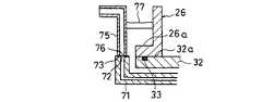
図4は第2実施形態の要部を示す。
【0034】
この構造では、炉口部材26の周壁に貫通させてパージガス供給管65が設けられており、パージガス供給管65の先端部が下方にL字形に曲げられている。そして、先端開口66の位置が、炉口部材26のフランジ26aの下面(合わせ面)と同レベルに設定され、シールキャップ32をフランジ26aに密着させた際に、パージガス供給管65の先端開口66が、下側のパージガス導入管51の基端開口52と連通するようになっている。パージガス導入管51側の構成は第1実施形態と同様である。なお、反応管23、24内を高温にする場合、炉内に近い側にOリングがあると熱で溶けるおそれがあるので、この構造では、パージガス供給管65とパージガス導入管51の開口52、66の周縁のOリングは省略してある。この場合、パージガスを流通させる際の気密性は落ちるものの、外周側にシールリング33があるので、炉外に漏れるおそれはない。
【0035】
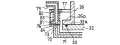
図5は第3実施形態の要部を示す。
【0036】
この構造では、シールキャップ32を貫通しない形でパージガスの導入経路を構成するべく、炉外に、パージガス導入管71とパージガス供給管75が配されている。即ち、シールリング33の外側において両者が接続されるように、パージガス導入管71とパージガス供給管75が、シールリング33の外側に設けられている。パージガス導入管71の先端は、第1実施形態と同様に、連結筒の導入ポートに接続されている(図示せず)。また、パージガス導入管71の基端開口72は、シールキャップ32の上面(合わせ面)32aとほぼ同レベルの位置に、上向き垂直に配されている。
【0037】
一方、パージガス供給管75の先端開口76は、シールキャップ26のフランジ26aの下面(合わせ面)とほぼ同レベルの位置に、下向き垂直に配されている。そして、シールキャップ32を炉口部材26のフランジ26aに密着させた際に、同時に、上側のパージガス供給管75の先端開口76と下側のパージガス導入管71の基端開口72が連通するようになっている。この場合、パージガス供給管75とパージガス導入管71の突き合わせ面(=開口の周縁部合わせ面)には、接続時の気密性保持のためのOリング73が配されている。なお、符号77で示すものは固定金具である。パージガス導入管71側にも、必要であれば固定金具を設ける。
【0038】
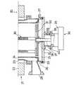
図6は第4実施形態の要部を示す。
【0039】
この第4実施形態の構造は、第3実施形態のものに新たに、パージガス供給管75とパージガス導入管71の先端突き合わせ面の密着性をより強めるための要素を付加したものである。即ち、上側のパージガス供給管75を下向きに付勢するためのバネ(付勢手段)83を新たに設け、バネ83の力で、パージガス導入管71とパージガス供給管75の連通用開口の周縁部合わせ面の密着度を高めるようにしている。
【0040】
この場合、固定金具77に一方のバネ受部82を設け、パージガス供給管75の下端に他方のバネ受部81を設け、両バネ受部81、82間に圧縮バネ83を介在させることで、パージガス供給管75の先端部に下向きの付勢力を与えている。そして、固定金具77の下端に設けたストッパ84で、パージガス供給管75の下降限位置を、フランジ26aの下面位置よりも下位レベルに定めることで、パージガス導入管71を上昇させてパージガス供給管75の下端に突き合わせせた際に、突き合わせ面間に必要な密着力が発生するようになっている。このようにバネ83の力で密着させることにより、確実に連通部分の気密保持性能を高めることができる。
【0041】
【発明の効果】
以上説明したように、本発明によれば、パージガスを連結筒に供給する管路のうち、管路の先端部分であるパージガス導入管を可動側(連結筒側)に設け、管路の基端部分であるパージガス供給管を固定側(炉本体側)に設け、シールキャップで炉口を塞いだときに、パージガス供給管とパージガス導入管が接続されるように構成したので、パージガス配管をボートエレベータの昇降スライダ等の可動部分を通す必要がなくなる。従って、配管をボートの動きに追従させるようにフレキシブルにする必要がなくなり、金属製の固定配管で構成することができる。その結果、外部不純ガスのパージガスへの混入を防止することができると共に、配管の損傷による外部へのパージガス漏れも確実に防止することができる。よって、炉内雰囲気を高純度に保つことができて、生成膜の特性向上と腐食防止等の種々の効果を奏することができる。
【図面の簡単な説明】
【図1】本発明の第1実施形態のボートを挿入する前の状態を示す側断面図である。
【図2】図1のII矢視図である。
【図3】本発明の第1実施形態のボートを挿入した後の状態を示す側断面図である。
【図4】本発明の第2実施形態の要部断面図である。
【図5】本発明の第3実施形態の要部断面図である。
【図6】本発明の第4実施形態の要部断面図である。
【図7】本発明で問題とする縦型炉を備えた半導体製造装置の概略斜視図である。
【図8】従来の縦型炉の下部構造の側断面図である。
【図9】従来の縦型炉の下部構造において、パージガスの供給経路の通し方を示す側面図である。
【符号の説明】
20 縦型炉
25 炉口
21 炉本体
30 ボート
31 設置台
32 シールキャップ
32a 上面(合わせ面)
33 シールリング
35 回転機構
36 本体部
37 回転軸
38 中心孔
39 回転軸シール
40 連結筒
50 導入ポート
51 パージガス導入管
52 基端開口
55 パージガス供給管
56 先端開口[0001]
BACKGROUND OF THE INVENTION
The present invention relates to a semiconductor manufacturing apparatus that performs diffusion / CVD (chemical vapor deposition) belonging to a pretreatment process among semiconductor manufacturing processes, and more particularly to a furnace opening structure.
[0002]
[Prior art]
An outline of a semiconductor manufacturing apparatus having a vertical furnace will be described with reference to FIG.
[0003]
This semiconductor manufacturing apparatus includes a
[0004]
A wafer transfer machine 11 is installed on the side of the
[0005]
When processing the
[0006]
FIG. 8 shows a detailed example of the lower structure in the case of the CVD apparatus of the
[0007]
What is indicated by
[0008]
Between the
[0009]
According to this structure, when the substrate processing gas is introduced into the reaction chamber and the substrate is processed, the
[0010]
By the way, in this type of semiconductor manufacturing apparatus, a corrosive gas is introduced into the
[0011]
In order to prevent this, in the above structure, the
[0012]
FIG. 9 shows a conventional purge gas supply path.
[0013]
Since the purge gas introduction part (connecting cylinder 40) is a movable part that moves up and down together with the boat (not shown in the figure), conventionally, a synthetic resin or metal flexible tube is used as the purge
[0014]
[Problems to be solved by the invention]
By the way, when a flexible tube made of metal or synthetic resin is used as the purge gas introduction pipe as in the prior art, the following problems may occur.
[0015]
That is, in the case of a flexible tube made of synthetic resin, since there is gas permeability, impure gas is mixed into the purge gas, which may enter the reaction tube and contaminate the inside of the reaction tube, or the purge gas may leak out of the piping. . Therefore, it cannot be used when a high purity furnace atmosphere is required.
[0016]
Further, in the case of a metal flexible tube, there is a problem in durability when the deformation is repeated, and there is a possibility that gas leakage occurs due to damage of the tube when used for a long time.
[0017]
In consideration of the above circumstances, the present invention improves the purge gas introduction path for protecting the rotary shaft seal, thereby preventing the entry of external impurity gas into the purge gas and preventing the purge gas from leaking outside. An object of the present invention is to provide a semiconductor manufacturing apparatus.
[0018]
[Means for Solving the Problems]
The present invention includes a furnace body in which a boat loaded with a wafer is inserted and withdrawn from a furnace port at the lower end, a seal cap that is lifted and lowered together with a boat installation base by a lifting mechanism to open and close the furnace port, and a lower part than the seal cap. A main body is disposed on the side so as to move up and down together with the seal cap, and a rotating shaft protruding upward passes through the center hole of the seal cap and is fixed to the installation table. A rotating mechanism that rotates inside, and a connecting cylinder interposed between the main body portion of the rotating mechanism and the seal cap so as to separate the rotary shaft seal disposed on the main body portion side of the rotating mechanism from the seal cap. In the semiconductor manufacturing apparatus, the connection cylinder is provided with an introduction port for introducing purge gas into the connection cylinder, and the tip of the purge gas introduction pipe is connected to the introduction port. A base end opening of the purge gas introduction pipe is provided upward at the level of the mating surface with respect to the furnace port of the seal cap, while a purge gas supply pipe is provided on the furnace body side, and a tip opening of the purge gas supply pipe is When the seal cap closes the furnace port, the seal cap is provided in a downward direction at a position that is in airtight communication with the proximal end opening of the purge gas introduction pipe.
[0019]
In this structure, the purge cap supply pipe and the purge gas introduction pipe are connected at the same time as the seal cap rises and closes the furnace body, and the purge gas can be introduced into the connecting cylinder through these pipe lines. In this way, the purge gas pipe is disconnected on the movable side (connecting cylinder side) and the fixed side (furnace body side), and both are connected when the furnace port is closed with the seal cap. There is no need to be flexible to follow the movement of the boat. Further, even when a flexible tube is used, the movement can be extremely reduced.
[0020]
In the present invention, it is preferable to dispose the proximal end opening of the purge gas introduction pipe and the distal end opening of the purge gas supply pipe on the inner side of the seal ring for maintaining the airtightness in the furnace provided on the mating surface of the seal cap and the furnace body. . In this structure, since the communication part of the purge gas introduction pipe and the purge gas supply pipe is located inside the area sealed by the seal ring, even if the purge gas leaks from the communication part, the seal ring brings it out of the furnace. Leakage is prevented.
[0021]
In the present invention, the proximal end opening of the purge gas introduction pipe and the distal end opening of the purge gas supply pipe are arranged outside the seal ring for maintaining the airtightness in the furnace provided on the mating surface of the seal cap and the furnace body. May be. In this structure, since the communicating portion of the purge gas introduction pipe and the purge gas supply pipe is located outside the seal ring, the purge gas introduction pipe and the purge gas supply pipe can be provided outside the furnace, that is, outside the reaction chamber and the seal cap. Therefore, the configuration can be simplified.
[0022]
In the above invention, it is preferable that an O-ring that surrounds only the communicating portion of the base end opening and the front end opening is provided between the peripheral edge joining surfaces of the base end opening of the purge gas introduction pipe and the front end opening of the purge gas supply pipe. In this structure, the airtightness of the communicating portion is maintained by the O-ring.
[0023]
Further, in the above invention, when the peripheral end mating surfaces of the proximal end opening of the purge gas introducing pipe and the distal end opening of the purge gas supply pipe are in contact with each other, the purge gas supply pipe is biased in a direction in which the contact between both the mating faces is strengthened. It is preferable to provide means. In this structure, since the degree of adhesion of the peripheral surface mating surfaces of the communication opening of the purge gas introduction pipe and the purge gas supply pipe can be increased by the urging means, the airtight holding performance of the communication portion is enhanced.
[0024]
DETAILED DESCRIPTION OF THE INVENTION
Hereinafter, embodiments of the present invention will be described with reference to the drawings.
[0025]
1 to 3 show a first embodiment, FIG. 1 is a side sectional view showing a state before the
[0026]
As shown in FIG. 1, in the vertical structure of the vertical furnace, a large
[0027]
Connected to the
[0028]
A purge
[0029]
Next, the operation will be described.
[0030]
In this structure, as shown in FIG. 3, when the boat elevator is driven to raise the
[0031]
As described above, the purge gas pipe line is separated on the movable side (connecting
[0032]
Further, in this embodiment, since the purge
[0033]
FIG. 4 shows a main part of the second embodiment.
[0034]
In this structure, a purge
[0035]
FIG. 5 shows a main part of the third embodiment.
[0036]
In this structure, a purge
[0037]
On the other hand, the front end opening 76 of the purge
[0038]
FIG. 6 shows a main part of the fourth embodiment.
[0039]
The structure of the fourth embodiment is a structure in which an element for further enhancing the adhesion of the tip butting surfaces of the purge
[0040]
In this case, one fixing
[0041]
【The invention's effect】
As described above, according to the present invention, the purge gas introduction pipe which is the distal end portion of the pipe among the pipes for supplying the purge gas to the connection cylinder is provided on the movable side (connection cylinder side), and the base end of the pipe The purge gas supply pipe, which is a part, is provided on the fixed side (furnace main body side), and when the furnace port is closed with a seal cap, the purge gas supply pipe and purge gas introduction pipe are connected. There is no need to pass a movable part such as an elevating slider. Therefore, it is not necessary to make the pipe flexible so as to follow the movement of the boat, and the pipe can be constituted by a metal fixed pipe. As a result, it is possible to prevent the external impurity gas from being mixed into the purge gas, and to reliably prevent the purge gas from leaking to the outside due to damage to the piping. Therefore, the atmosphere in the furnace can be maintained at a high purity, and various effects such as improvement of the properties of the formed film and prevention of corrosion can be achieved.
[Brief description of the drawings]
FIG. 1 is a side sectional view showing a state before inserting a boat according to a first embodiment of the present invention.
FIG. 2 is a view taken in the direction of arrow II in FIG.
FIG. 3 is a side sectional view showing a state after inserting the boat of the first embodiment of the present invention.
FIG. 4 is a cross-sectional view of a main part of a second embodiment of the present invention.
FIG. 5 is a cross-sectional view of a main part of a third embodiment of the present invention.
FIG. 6 is a cross-sectional view of a main part of a fourth embodiment of the present invention.
FIG. 7 is a schematic perspective view of a semiconductor manufacturing apparatus including a vertical furnace which is a problem in the present invention.
FIG. 8 is a side sectional view of a lower structure of a conventional vertical furnace.
FIG. 9 is a side view showing how to pass a purge gas supply path in a lower structure of a conventional vertical furnace.
[Explanation of symbols]
20
33
Claims (3)
Translated fromJapanese前記炉口を開閉するべく昇降機構によって前記ボートの設置台と共に昇降させられるシールキャップと、
このシールキャップより下側に該シールキャップと共に昇降するよう本体部が配設され、回転軸を駆動することで設置台を水平面内で回転させる回転機構と、前記回転機構の本体部と前記シールキャップとの間に介在された連結筒とを備えた半導体製造装置において、
前記連結筒に、不活性ガスをパージガスとして該連結筒内に導入するための導入ポートを設けると共に、該導入ポートにパージガス導入管の先端を接続して、該パージガス導入管の基端開口を上向きに設け、一方、前記炉本体側にパージガス供給管を設け、該パージガス供給管の先端開口を、前記シールキャップが炉口を塞いだとき前記パージガス導入管の基端開口と気密に連通する位置に下向きに設けたことを特徴とする半導体製造装置。A furnace body into which a boat carrying wafers is inserted and withdrawn from a furnace port at the lower end; and
A seal cap that is lifted and lowered together with the boat installation base by a lifting mechanism to open and close the furnace port;
A main body portion is disposed below the seal cap so as to move up and down together with the seal cap, and a rotation mechanism that rotates the installation base in a horizontal plane by driving a rotation shaft, a main body portion of the rotation mechanism, and the seal cap In a semiconductor manufacturing apparatus provided with a connecting cylinder interposed between
The connection cylinder is provided with an introduction port for introducingan inert gas into the connection cylinderas a purge gas, and the distal end of the purge gas introduction pipe is connected to the introduction port so that the proximal end opening of the purge gas introduction pipe faces upward On the other hand, a purge gas supply pipe is provided on the furnace main body side, and the front end opening of the purge gas supply pipe is in a position where it is in airtight communication with the base end opening of the purge gas introduction pipe when the seal cap closes the furnace port. A semiconductor manufacturing apparatus provided downward.
前記炉口を開閉するべく昇降機構によって前記ボートの設置台と共に昇降させられるシールキャップと、A seal cap that is lifted and lowered together with the boat installation base by a lifting mechanism to open and close the furnace port;
このシールキャップより下側に該シールキャップと共に昇降するよう本体部が配設され、回転軸を駆動することで設置台を水平面内で回転させる回転機構と、前記回転機構の本体部と前記シールキャップとの間に介在された連結筒とを備えた半導体製造装置において、A main body portion is disposed below the seal cap so as to move up and down together with the seal cap, and a rotation mechanism that rotates the installation base in a horizontal plane by driving a rotation shaft, a main body portion of the rotation mechanism, and the seal cap In a semiconductor manufacturing apparatus provided with a connecting cylinder interposed between
前記連結筒に、不活性ガスをパージガスとして該連結筒内に導入するための導入ポートを設けると共に、該導入ポートにパージガス導入管の先端を接続して、該パージガス導入管の基端開口を上向きに設け、一方、前記炉本体側にパージガス供給管を設け、該パージガス供給管の先端開口を、前記シールキャップが炉口を塞いだとき前記パージガス導入管の基端開口と気密に連通する位置に下向きに設け、前記パージガス供給管の先端開口と前記パージガス導入管の基端開口が、前記炉本体と前記シールキャップを密閉するシールリングの外側に位置することを特徴とする半導体製造装置。The connection cylinder is provided with an introduction port for introducing an inert gas into the connection cylinder as a purge gas, and the distal end of the purge gas introduction pipe is connected to the introduction port so that the proximal end opening of the purge gas introduction pipe faces upward On the other hand, a purge gas supply pipe is provided on the furnace main body side, and the front end opening of the purge gas supply pipe is in a position where it is in airtight communication with the base end opening of the purge gas introduction pipe when the seal cap closes the furnace port. A semiconductor manufacturing apparatus, characterized in that the front end opening of the purge gas supply pipe and the base end opening of the purge gas introduction pipe are located outside a seal ring that seals the furnace body and the seal cap.
前記炉口を開閉するべく昇降機構によって前記ボートの設置台と共に昇降させられるシールキャップと、A seal cap that is lifted and lowered together with the boat installation base by a lifting mechanism to open and close the furnace port;
このシールキャップより下側に該シールキャップと共に昇降するよう本体部が配設され、回転軸を駆動することで設置台を水平面内で回転させる回転機構と、前記回転機構の本体部と前記シールキャップとの間に介在された連結筒とを備えた半導体製造装置において、A main body portion is disposed below the seal cap so as to move up and down together with the seal cap, and a rotation mechanism that rotates the installation base in a horizontal plane by driving a rotation shaft, a main body portion of the rotation mechanism, and the seal cap In a semiconductor manufacturing apparatus provided with a connecting cylinder interposed between
前記連結筒に、不活性ガスをパージガスとして該連結筒内に導入するための導入ポートを設けると共に、該導入ポートにパージガス導入管の先端を接続して、該パージガス導入管の基端開口を、前記シールキャップの炉口に対する合わせ面レベルに上向きに設け、一方、前記炉本体側にパージガス供給管を設け、該パージガス供給管の先端開口を、前記シールキャップが炉口を塞いだとき前記パージガス導入管の基端開口と気密に連通する位置に下向きに設け、前記パージガス供給管の先端開口と前記パージガス導入管の基端開口が、前記炉本体と前記シールキャップを密閉するシールリングの外側に位置することを特徴とする半導体製造装置。The connection cylinder is provided with an introduction port for introducing an inert gas into the connection cylinder as a purge gas, and the distal end of the purge gas introduction pipe is connected to the introduction port so that the proximal end opening of the purge gas introduction pipe is formed. Provided at the level of the mating surface of the seal cap with respect to the furnace port, while a purge gas supply pipe is provided on the furnace body side, the opening of the purge gas supply pipe is opened, and the purge gas is introduced when the seal cap closes the furnace port. A downward opening is provided at a position in airtight communication with the proximal end opening of the pipe, and the distal end opening of the purge gas supply pipe and the proximal end opening of the purge gas introduction pipe are located outside the seal ring that seals the furnace body and the seal cap. A semiconductor manufacturing apparatus.
Priority Applications (1)
| Application Number | Priority Date | Filing Date | Title |
|---|---|---|---|
| JP17144197AJP3785247B2 (en) | 1997-06-27 | 1997-06-27 | Semiconductor manufacturing equipment |
Applications Claiming Priority (1)
| Application Number | Priority Date | Filing Date | Title |
|---|---|---|---|
| JP17144197AJP3785247B2 (en) | 1997-06-27 | 1997-06-27 | Semiconductor manufacturing equipment |
Publications (3)
| Publication Number | Publication Date |
|---|---|
| JPH1116846A JPH1116846A (en) | 1999-01-22 |
| JPH1116846A5 JPH1116846A5 (en) | 2005-05-12 |
| JP3785247B2true JP3785247B2 (en) | 2006-06-14 |
Family
ID=15923186
Family Applications (1)
| Application Number | Title | Priority Date | Filing Date |
|---|---|---|---|
| JP17144197AExpired - Fee RelatedJP3785247B2 (en) | 1997-06-27 | 1997-06-27 | Semiconductor manufacturing equipment |
Country Status (1)
| Country | Link |
|---|---|
| JP (1) | JP3785247B2 (en) |
Families Citing this family (4)
| Publication number | Priority date | Publication date | Assignee | Title |
|---|---|---|---|---|
| KR100835102B1 (en) | 2002-12-16 | 2008-06-03 | 동부일렉트로닉스 주식회사 | Boat rotator |
| JP6180276B2 (en)* | 2013-10-25 | 2017-08-16 | 光洋サーモシステム株式会社 | Heat treatment equipment |
| KR102680412B1 (en)* | 2018-11-27 | 2024-07-02 | 삼성전자주식회사 | Apparatus for semiconductor treatment and system for semiconductor treatment |
| WO2024012188A1 (en)* | 2022-07-13 | 2024-01-18 | 北京北方华创微电子装备有限公司 | Semiconductor process apparatus |
- 1997
- 1997-06-27JPJP17144197Apatent/JP3785247B2/ennot_activeExpired - Fee Related
Also Published As
| Publication number | Publication date |
|---|---|
| JPH1116846A (en) | 1999-01-22 |
Similar Documents
| Publication | Publication Date | Title |
|---|---|---|
| KR100330130B1 (en) | Heat treatment method and device | |
| US6283175B1 (en) | Enveloping device and vertical heat-treating apparatus for semiconductor process system | |
| US6030457A (en) | Substrate processing apparatus | |
| CN111066132B (en) | Gas delivery system for high pressure processing chamber | |
| TWI823166B (en) | Load port operation in electronic device manufacturing apparatus, systems, and methods | |
| JP3579278B2 (en) | Vertical heat treatment device and sealing device | |
| JP3218488B2 (en) | Processing equipment | |
| JP5237133B2 (en) | Substrate processing equipment | |
| TWI498989B (en) | Gas port construction and processing device | |
| JP3785247B2 (en) | Semiconductor manufacturing equipment | |
| KR102540307B1 (en) | Sealing device capable of linear motion and rotating motion and processing apparatus for semiconductor substrate using the same | |
| CN113053785B (en) | Semiconductor processing equipment | |
| JPWO2004086474A1 (en) | Container, container manufacturing method, substrate processing apparatus, and semiconductor device manufacturing method | |
| JP2002009010A (en) | Thermal treatment and method | |
| JP2007073746A (en) | Substrate processing equipment | |
| JP3449636B2 (en) | Semiconductor manufacturing equipment | |
| EP1285977A2 (en) | Apparatus and method for insulating a seal in a process chamber | |
| JP2691159B2 (en) | Vertical heat treatment equipment | |
| JP3543987B2 (en) | Processing equipment | |
| JP2601830B2 (en) | Heat treatment equipment | |
| JP3269881B2 (en) | Semiconductor manufacturing equipment | |
| JP3798915B2 (en) | Vertical heat treatment equipment | |
| KR100622201B1 (en) | Plasma processing apparatus for lcd substrate | |
| JPH0729841A (en) | Heat treatment furnace | |
| JP4451653B2 (en) | Substrate processing apparatus and semiconductor manufacturing method |
Legal Events
| Date | Code | Title | Description |
|---|---|---|---|
| A521 | Written amendment | Free format text:JAPANESE INTERMEDIATE CODE: A523 Effective date:20040628 | |
| A621 | Written request for application examination | Free format text:JAPANESE INTERMEDIATE CODE: A621 Effective date:20040628 | |
| A977 | Report on retrieval | Free format text:JAPANESE INTERMEDIATE CODE: A971007 Effective date:20050601 | |
| TRDD | Decision of grant or rejection written | ||
| A01 | Written decision to grant a patent or to grant a registration (utility model) | Free format text:JAPANESE INTERMEDIATE CODE: A01 Effective date:20060314 | |
| A61 | First payment of annual fees (during grant procedure) | Free format text:JAPANESE INTERMEDIATE CODE: A61 Effective date:20060317 | |
| R150 | Certificate of patent or registration of utility model | Free format text:JAPANESE INTERMEDIATE CODE: R150 | |
| FPAY | Renewal fee payment (event date is renewal date of database) | Free format text:PAYMENT UNTIL: 20100324 Year of fee payment:4 | |
| FPAY | Renewal fee payment (event date is renewal date of database) | Free format text:PAYMENT UNTIL: 20100324 Year of fee payment:4 | |
| FPAY | Renewal fee payment (event date is renewal date of database) | Free format text:PAYMENT UNTIL: 20110324 Year of fee payment:5 | |
| FPAY | Renewal fee payment (event date is renewal date of database) | Free format text:PAYMENT UNTIL: 20120324 Year of fee payment:6 | |
| FPAY | Renewal fee payment (event date is renewal date of database) | Free format text:PAYMENT UNTIL: 20120324 Year of fee payment:6 | |
| FPAY | Renewal fee payment (event date is renewal date of database) | Free format text:PAYMENT UNTIL: 20130324 Year of fee payment:7 | |
| FPAY | Renewal fee payment (event date is renewal date of database) | Free format text:PAYMENT UNTIL: 20130324 Year of fee payment:7 | |
| FPAY | Renewal fee payment (event date is renewal date of database) | Free format text:PAYMENT UNTIL: 20140324 Year of fee payment:8 | |
| LAPS | Cancellation because of no payment of annual fees |