JP3784875B2 - Identification method and apparatus - Google Patents
Identification method and apparatusDownload PDFInfo
- Publication number
- JP3784875B2 JP3784875B2JP02519696AJP2519696AJP3784875B2JP 3784875 B2JP3784875 B2JP 3784875B2JP 02519696 AJP02519696 AJP 02519696AJP 2519696 AJP2519696 AJP 2519696AJP 3784875 B2JP3784875 B2JP 3784875B2
- Authority
- JP
- Japan
- Prior art keywords
- identification
- pattern
- sensor
- light
- transfer path
- Prior art date
- Legal status (The legal status is an assumption and is not a legal conclusion. Google has not performed a legal analysis and makes no representation as to the accuracy of the status listed.)
- Expired - Fee Related
Links
Images


Classifications
- G—PHYSICS
- G06—COMPUTING OR CALCULATING; COUNTING
- G06K—GRAPHICAL DATA READING; PRESENTATION OF DATA; RECORD CARRIERS; HANDLING RECORD CARRIERS
- G06K7/00—Methods or arrangements for sensing record carriers, e.g. for reading patterns
- G06K7/10—Methods or arrangements for sensing record carriers, e.g. for reading patterns by electromagnetic radiation, e.g. optical sensing; by corpuscular radiation
- G06K7/14—Methods or arrangements for sensing record carriers, e.g. for reading patterns by electromagnetic radiation, e.g. optical sensing; by corpuscular radiation using light without selection of wavelength, e.g. sensing reflected white light
- G—PHYSICS
- G06—COMPUTING OR CALCULATING; COUNTING
- G06K—GRAPHICAL DATA READING; PRESENTATION OF DATA; RECORD CARRIERS; HANDLING RECORD CARRIERS
- G06K7/00—Methods or arrangements for sensing record carriers, e.g. for reading patterns
- G06K7/02—Methods or arrangements for sensing record carriers, e.g. for reading patterns by pneumatic or hydraulic means, e.g. sensing punched holes with compressed air; by sonic means ; by ultrasonic means
- G—PHYSICS
- G06—COMPUTING OR CALCULATING; COUNTING
- G06K—GRAPHICAL DATA READING; PRESENTATION OF DATA; RECORD CARRIERS; HANDLING RECORD CARRIERS
- G06K19/00—Record carriers for use with machines and with at least a part designed to carry digital markings
- G06K19/06—Record carriers for use with machines and with at least a part designed to carry digital markings characterised by the kind of the digital marking, e.g. shape, nature, code
- G06K19/06009—Record carriers for use with machines and with at least a part designed to carry digital markings characterised by the kind of the digital marking, e.g. shape, nature, code with optically detectable marking
- G—PHYSICS
- G06—COMPUTING OR CALCULATING; COUNTING
- G06K—GRAPHICAL DATA READING; PRESENTATION OF DATA; RECORD CARRIERS; HANDLING RECORD CARRIERS
- G06K7/00—Methods or arrangements for sensing record carriers, e.g. for reading patterns
- G06K7/10—Methods or arrangements for sensing record carriers, e.g. for reading patterns by electromagnetic radiation, e.g. optical sensing; by corpuscular radiation
- G06K7/10544—Methods or arrangements for sensing record carriers, e.g. for reading patterns by electromagnetic radiation, e.g. optical sensing; by corpuscular radiation by scanning of the records by radiation in the optical part of the electromagnetic spectrum
- G06K7/10821—Methods or arrangements for sensing record carriers, e.g. for reading patterns by electromagnetic radiation, e.g. optical sensing; by corpuscular radiation by scanning of the records by radiation in the optical part of the electromagnetic spectrum further details of bar or optical code scanning devices
- G06K7/10861—Methods or arrangements for sensing record carriers, e.g. for reading patterns by electromagnetic radiation, e.g. optical sensing; by corpuscular radiation by scanning of the records by radiation in the optical part of the electromagnetic spectrum further details of bar or optical code scanning devices sensing of data fields affixed to objects or articles, e.g. coded labels
Landscapes
- Physics & Mathematics (AREA)
- Engineering & Computer Science (AREA)
- General Physics & Mathematics (AREA)
- Theoretical Computer Science (AREA)
- Electromagnetism (AREA)
- Artificial Intelligence (AREA)
- Computer Vision & Pattern Recognition (AREA)
- Health & Medical Sciences (AREA)
- General Health & Medical Sciences (AREA)
- Toxicology (AREA)
- Discharge Of Articles From Conveyors (AREA)
- Geophysics And Detection Of Objects (AREA)
Description
Translated fromJapanese【0001】
【発明の属する技術分野】
本発明は、調剤師のIDカードや、薬剤包装機における薬剤カートリッジ等、各種の物品を識別する識別方法及びその装置に関するものである。
【0002】
【従来の技術】
従来、カード等の各種物品を識別する方法として、被識別体に個人番号、所属等の識別情報を磁気記録しておき、これを磁気ヘッドで読み取る方法が一般的である。さらに簡便な方法としては、図12に示すように、被識別体41に識別ホール42の有無を組み合わせた複数(図では10個)の点からなる識別パターン43を設ける一方、互いに対向して配置された光送信器44と光受信器45からなる識別センサ46を前記識別パターン43の点数に相当する数だけ配置し、光送信器44と光受信器45の間に被識別体41を挿入したときに各光送信器44から送信される光を光受信器45が受信するか否かによって、被識別体41を識別する方法がある。
【0003】
【発明が解決しようとする課題】
しかしながら、図12に示す従来の方法では、識別センサ46が識別パターン43の点数だけ必要であるので、大きな設置スペースが必要であるうえ、高価である。また、被識別体41の挿入が不完全であると、光送信器44からの光を光受信器45で受信することが困難となり、識別不能や誤認が生じる等の問題があった。
本発明は、かかる問題点に鑑みてなされたもので、数の少ない識別センサで被識別体を確実に、かつ、安価に識別することができる識別方法及びその装置を提供することを課題とする。
【0004】
【課題を解決するための手段】
前記課題を解決するため、第1の発明による識別方法は、被識別体に複数の基準ホールによって基準パターンを設けるとともに、当該基準パターンの各基準ホールに対応する複数の点に識別ホールの有無によって識別パターンを付与し、前記被識別体を基準パターン又は識別パターンに平行な移送路に沿って移送させ、前記移送路の一方の側から当該移送路を横切る方向に光又は超音波を送信し、前記移送路の他方の側で前記基準パターンを通して前記光又は超音波を受信したときに、前記識別ターンを通して前記光又は超音波を受信するか否かによって被識別体の識別パターンを識別するものである。
この識別方法では、基準パターンを識別してから識別パターンを識別するので、被識別体の移送速度が不規則であっても、識別可能である。
【0005】
第2の発明による識別装置は、前記第2の発明の方法を実施するための装置であって、複数の基準ホールによって基準パターンが設けられるとともに、当該基準パターンの各基準ホールと対応する複数の点に識別ホールの有無によって識別パターンが付与され、前記基準パターン又は識別パターンに平行な移送路に沿って移送される被識別体と、
前記移送路の一方の側から当該移送路を横切る方向に光又は超音波を送信し、前記移送路の他方の側で前記基準パターンの各基準ホールを通して前記光又は超音波を受信する基準センサと、
前記移送路の一方の側から当該移送路を横切る方向に光又は超音波を送信し、前記基準センサが基準パターンを識別したときに、前記識別パターンを通して前記光又は超音波を受信するか否かによって被識別体の識別パターンを識別する識別センサとからなるものである。
【0006】
前記第2の発明の好ましい態様では、前記被識別体の識別パターンは、基準パターンに対して被識別体の移送路に沿ってずらして設けられ、
前記識別センサは、前記基準センサが基準パターンを識別して一定時間(x)経過したときに、前記識別パターンを通して前記光又は超音波を受信するか否かによって被識別体の識別パターンを識別する。ここで、基準パターンと識別パターンをずらせる代わりに、前記識別センサを、前記基準センサに対して被識別体の移送方向に沿ってずらして設けてもよい。また、前記一定時間(x)は、基準パターンのピッチの1/2以下に相当する時間とするのが好ましい。
【0007】
これにより、被識別体をある一定の方向に移送させたときには、基準パターンを識別してから(x)時間経過後に識別パターンが識別されるが、逆の方向に移送させたときには(x+a)時間経過後に識別パターンが識別される。したがって、被識別体をある方向に移送したときのみ識別パターンが識別され、逆の方向に移送したときには識別されない。この結果、被識別体の識別パターンの識別だけでなく、その送り込みと引き戻し、装着(取付け)と脱着(取外し)が識別される。このため、被識別体を送り込み又は装着したときに識別パターンを識別してそのデータを登録し、被識別体を引き戻し又は脱着したときにその登録データを消去することが可能となる。
【0008】
他の好ましい態様として、前記被識別体は、モータベースに着脱可能な薬剤カートリッジとすることができる。これにより、モータベースに装着される薬剤カートリッジが確実に識別される。また、薬剤カートリッジのモータベースへの装着場所が予め決められている場合に、その薬剤カートリッジが異なるモータベースに装着されたときには、その薬剤カートリッジを識別することによってそれが誤装着であることを容易に判断することができる。
【0009】
さらに他の好ましい態様では、前記薬剤カートリッジは、当該薬剤カートリッジが前記モータベースに装着完了したときに前記基準センサ又は識別センサの光又は超音波が通過する装着完了検出ホールを有する。これにより、薬剤カートリッジの装着完了が正確に検出されることから、モータベースの確実な動作が保証される。
【0010】
【発明の実施の形態】
以下、本発明の実施の形態を添付図面に従って説明する。
図1は、識別装置を示す。この識別装置は、病院や薬局において調剤師が所有する被識別体としてのIDカード1と、該IDカード1を識別するためのカードリーダ2とからなる。IDカード1には、カードリーダ2への挿入方向(図中矢印で示す。)に沿って所定ピッチ離れた10の点に識別ホール3の有無を設けることによって調剤師の識別番号に対応する10桁の識別パターン4が付与されている。図1において、白丸は識別ホール3が穿設された点、黒丸は識別ホール3が穿設されていない点を示す。
【0011】
カードリーダ2には、前記IDカード1が挿入される移送路となる溝5が形成されている。そしてこの溝5の入口端と出口端のほぼ中間に、光送信器6と光受信器7とからなる識別センサ8が設けられている。光送信器6は発光素子からなり、図2(a)に示すように、溝5の一方の側に配置されている。光受信器7は受光素子からなり、前記光受信器6と対向するように溝5の他方の側に配置されている。これにより、光送信器6から発射された光が溝5を横切って光受信器7に受信されるようになっている。また、光送信器6と光受信器7は、溝5の底からの高さがIDカード1の下端から識別ホール3までの高さに一致するように配置されている。
【0012】
前記カードリーダ2は、登録された多数の調剤師の識別番号を予め記憶しておく記憶部9と、前記識別センサ8の光送信器6に光送信信号を出力するとともに、光受信器7からの光受信信号に基づいてIDカード1を識別する制御部10を有している。
【0013】
次に、前記構成からなる識別装置の動作について説明する。
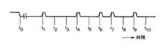
カードリーダ2の制御部10は、まず光送信器6に光送信信号を出力して、光送信器6に特定の光を送信させ、IDカード1が挿入されるまで待機する。この時点では、光受信器7は光送信器6から送信された光を受信するが、この受信信号は、図3中t0時点以前に示すように連続したオン信号であるため、制御部10は識別信号とは判断しない。IDカード1がカードリーダ2の溝5に挿入されて一定速度で移送されると、IDカード1の先端が光送信器6から送信される光を遮断する。このとき、図3に示すようにt0時点において光受信器7の受信信号はオフとなるが、これは連続したオフ信号であるため、制御部10は識別信号とは判断しない。
【0014】
IDカード1がさらに移送されて、識別パターン4の第1桁の点が識別センサ8の位置に達すると、その第1桁に識別ホール3があれば光送信器6から送信された光が当該識別ホール3を通過し、なければ遮断される。第1桁の点が識別センサ8を通過してから一定時間後に第2桁の点が識別センサ8を通過し、同様に第10桁までの各点が識別センサ8を順次通過する結果、図3中t1,t2,…,t10に示すように、各桁の点が識別センサ8を通過する時点毎に識別パターン4に応じたオン,オフ信号が得られる。制御部10は、このオン,オフ信号を図2(b)に示すように1と0からなる識別データとして把握し、記憶部9に記憶された登録データと比較し、一致するものがあるか否によって挿入されたIDカード1の真偽を判別する。
【0015】
なお、この識別装置において、IDカード1の挿入速度が利用者によって不規則となる場合には、一定時間ピッチで識別パターン4の識別信号が得られなくなり、識別が困難となる。このような場合には、カードリーダ2にIDカード1を一定速度で移送するローラ等の移送機構を設けるのが好ましい。
【0016】
図4は、本発明の第1実施形態の識別装置を示す。この識別装置は、IDカード1に識別パターン4の外に基準パターン11を設け、カードリーダ2の識別センサ8に加えて基準センサ12を設けた以外は、前記図1の識別装置と実質的に同一であり、対応する部分には同一符号を付して説明を省略する。
【0017】
IDカードの基準パターン11は、前記10桁の識別パターン4の上方に配置され、当該識別パターン4の10桁の全ての点に対応して基準ホール13が形成されている。また、この基準パターン11の前方には、基準パターン11の基準ホール13の径よりも長い寸法のスリット14が形成されている。
【0018】
カードリーダ2の基準センサ12は、前記IDカード1の基準パターン11を識別するもので、図5(a)に示すように、識別センサ8と同様、前記溝5の両側に互いに対向して配置された光送信器15と光受信器16とからなっている。この基準センサ12は前記識別センサ8の上方に配置され、基準センサ12のカードリーダ2の溝5の底からの高さは、IDカード1の下端から基準ホール13までの寸法と同一になっている。
【0019】
次に、前記構成からなる識別装置の動作について説明する。
カードリーダ2の制御部10は、まず識別センサ8の光送信器6と基準センサ12の光送信器15に光送信信号を出力して、各光送信器6,15に特定の光を送信させ、IDカード1が挿入されるまで待機する。この時点では、光受信器7,16は光送信器6,15から送信された光を受信するが、この受信信号は、図6中t0時点以前に示すようにいずれも連続したオン信号であるため、制御部10は識別信号とは判断しない。IDカード1がカードリーダ2の溝5に挿入されて移送されると、IDカード1の先端が光送信器6,15から送信される光を遮断する。このとき、図6に示すようにt0時点において光受信器7,16の受信信号はオフとなるが、これは連続したオフ信号であるため、制御部10は識別信号とは判断しない。
【0020】
IDカード1がさらに移送され、基準パターン11のスリット14が基準センサ12の位置に達すると、基準センサ12の光送信器15から送信された光がスリット14を通過する。この結果、光受信器16は前記光送信器15からの光を図6に示すようにリセット信号として受信する。そして、このリセット信号に基づいて、制御部10は従前の識別データをリセットし、今から識別しようとする識別パターン4を待機する。
【0021】
IDカード1の基準パターン11の基準ホール13が基準センサ12の位置に到達する毎に、光送信器15から送信される光が当該基準ホール13を通過する。この結果、図6中t1,t2,…,t10に示すように、光受信器16は光送信器15からの光を受信するので、一定時間毎にオン,オフ信号が得られる。一方、識別パターン4の第1桁の点が識別センサ8の位置に達すると、その識別パターン4の第1桁に識別ホール3があれば光送信器6から送信された光が識別ホール3を通過し、なければ遮断される。第1桁の点が識別ホール3を通過してから一定時間後に第2桁の点が識別ホール3を通過し、同様に第10桁までの各点が識別ホール3を順次通過する結果、図6中t1,t2,…,t10に示すように、識別パターン4に応じたオン,オフ信号が得られる。制御部10は、基準センサ12の光受信器16がオン信号を受信したときに、識別センサ8の光受信器7がオン信号を受信するかオフ信号を受信するかによって図5(d)に示すように1と0からなる識別データとして把握し、記憶部9に記憶された登録データと比較し、一致するものがあるか否によって挿入されたIDカード1の真偽を判別する。
【0022】
このように、基準センサ12が基準パターン11を識別する毎に識別センサ8がIDカード1の識別パターン4を識別するため、IDカード1が挿入される速度が不規則であっても、確実にIDカード1の識別パターン4を識別することができる。
【0023】
図7は、本発明の第2実施形態を示す。この実施形態では、IDカード1の識別パターン4は、基準パターン11のピッチpの1/2未満の寸法Δpだけ移送(挿入)方向の後方にずらせて配置されている。この場合、IDカード1が図7に示す矢印方向に挿入されると、図8に示すように、基準パターン4に基づいて基準センサ12の光受信器16がオン信号を検出した後、寸法(Δp)に相当する時間(x)だけ遅れて識別センサ8の光受信器7がオン又はオフ信号を受信する。しかし、IDカード1が矢印方向と反対方向に引き戻されると、寸法(p−Δp)に相当する時間(x+a)だけ遅れて識別センサ8の光受信器7がオン又はオフ信号を受信する。したがって、IDカード1の挿入方向と引き戻し方向とで識別センサ8の光受信器7が受ける信号にずれが生じる。
【0024】
このため、制御部10は、基準センサ12の光受信器16が基準パターン11の信号を受けてから、(x)時間後に識別センサ12の光受信器16が識別パターンの信号を受ければIDカード1が挿入されたと判断し、(x+a)時間後に識別パターン4の信号を受ければIDカード1が引き戻されたと判断することができる。そして、これを利用して、制御部10は、IDカード1が挿入されたときには識別データを登録し、IDカード1が引き戻されたときにはその識別データを消去するような処理をすることができる。
【0025】
なお、このように基準パターン11と識別パターン4をずらせる代わりに、識別センサ8と基準センサ12の位置をIDカード1の移送(挿入)方向にずらせるようにしても、同様の効果が得られる。
【0026】
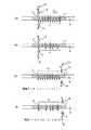
第9図は、本発明の第3実施形態を示す。この実施形態は、処方に応じてカプセルや錠剤等の薬剤を1分包づつ包装する薬剤包装機の薬剤フィーダ20に本発明の識別装置を適用したものである。この薬剤フィーダ20は、被識別体としての薬剤カートリッジ21と、該薬剤カートリッジ21が着脱自在に装着されるモータベース22とからなっている。
【0027】
薬剤カートリッジ21は、多数のカプセル等の薬剤を収容する蓋付きの容器で、その内側の底には外周にポケット23を有するロータ24が回転自在に設けられている。また、薬剤カートリッジ21の外側の底面には、図10に示すように、2つの突条板25がモータベース22への装着方向と平行に設けられている。これらの突条板25には、モータベース22の後述するガイド部材32と係合する係合突部26が形成されている。また、一方の突条板25には、前記図1の識別装置のIDカード1と同様に10桁の識別パターン4が付与されている。この識別パターン4は、薬剤カートリッジ21に収容される薬剤の薬名を示している。また、前記突条板25には、識別パターン4の後方に装着完了検出ホール27が穿設されている。
【0028】
モータベース22は、前記薬剤カートリッジ21のロータ24をギヤ28,29を介して回転駆動するモータ30と、薬剤カートリッジ21から取り出される薬剤を受け入れて図示しない包装装置に導く通路31とを有している。このモータベース22の上面には、前記薬剤カートリッジ21が矢印方向に装着されるときに、その2つの突条板25をガイドし、かつ、係合突部26を受け入れるガイド部材32が形成されている。そして、このガイド部材32には、前記薬剤カートリッジ21の装着が完了した状態においてその装着完了検出ホール27と対応する位置に、センサ取付穴33が形成されている。また、このセンサ取付穴33の両側には、前記図1の識別装置の識別センサ8と同様の光送信器6と光受信器7からなる識別センサ8が配設されている。
【0029】
前記構成からなる薬剤フィーダ20において、薬剤カートリッジ21をモータベース22の上に矢印方向に装着してゆくと、薬剤カートリッジ21の突条板25に付与された識別パターン4が前記図1の識別装置と同様にして識別センサ8によって識別される。この識別によって、薬剤カートリッジ21が装着されるモータベース22が予め設定されている場合には、正しい薬剤カートリッジ21がモータベース22に装着されたか否かが判断できる。また、薬剤カートリッジ21が装着されるモータベース22が任意である場合には、そのモータベース22に装着された薬剤カートリッジ21の薬剤名が判断できる。
【0030】
薬剤カートリッジ21がモータベース22に完全に装着されると、薬剤カートリッジ21の装着完了検出ホール27がセンサ取付穴33と完全に一致し、識別センサ8の光送信器6から送信された光が装着完了検出ホール27及びセンサ取付穴33を通過して光受信器7に受信される。また、薬剤カートリッジ21がモータベース22に完全に装着されないと、薬剤カートリッジ21の装着完了検出ホール27がセンサ取付穴33と一致せず、識別センサ8の光送信器6から送信された光は突条板25によって遮光されるので、光受信器7に受信されない。したがって、光受信器7が光送信器6からの光を受信したかどうかによって、薬剤カートリッジ21がモータベース22に完全装着されたか否かが判断できる。そして、この判断により薬剤カートリッジ21の装着が不完全なときにその旨を報知することによって、薬剤フィーダ20の動作不良を防止することができる。
【0031】
図11は、本発明の第4実施形態を示す。この実施形態は、薬剤カートリッジ21の突条板25に識別パターン4に加えて基準パターン11を設けるとともに、モータベース22に識別センサ8に加えて前記基準パターン11を識別する基準センサ12を設けた以外は、前記第3実施形態と実質的に同一であり、対応する部分には同一符号を付して説明を省略する。
【0032】
この第4実施形態では、前記第1実施形態のIDカード1と同様に、基準センサ12が基準パターン11の各基準ホール13を識別するごとに、識別センサ8の光受信器7が光送信器6からの光を受信するか否かによって薬剤カートリッジ21の識別パターン4を識別する。したがって、薬剤カートリッジ21が装着される速度が不規則であっても、確実に薬剤カートリッジ21の識別パターン4を識別することができる。
【0033】
なお、この第4実施形態においては、前記第2実施形態と同様にして、薬剤カートリッジ21の識別パターン4を基準パターン11に対して移送(装着)方向にずらして配置してもよいし、識別センサ8を基準センサ12に対して移送(装着)方向にずらして配置してもよい。
また、前記第4実施形態では、1つの突条板27に基準パターン11と識別パターン4を設けたが、2つの突条板27のうちの一方に基準パターン11、他方に識別パターン4を設けてもよい。
【0034】
さらに、以上の各実施形態では、識別センサ8、基準センサ12として、光を送受信するセンサを用いたが、超音波を送受信するセンサを用いてもよい。要は、被識別体であるIDカード1や薬剤カートリッジ21の突条板25に形成した識別ホール3や基準ホール13は貫通するが、それ以外の部分は貫通しない通信媒体を利用する。
【0035】
【発明の効果】
以上の説明から明らかなように、本発明によれば、送信器と受信器からなる1つの識別センサで被識別体の識別パターンを識別できるので、構成が簡単であり、装置が安価となる。
また、被識別体を移送中にその識別パターンを識別できるので、被識別体の挿入や装着が完了したか否かに拘わらず、確実に識別できる。
さらに、被識別体に基準パターンと識別パターンを付与することにより、被識別体の移送速度が不規則であっても正確に識別できる。
また、被識別体の基準パターンと識別パターンをずらせるか、あるいは基準センサと識別センサの位置をずらせることにより、被識別体が一定方向に移送されたときのみその識別パターンを識別することができる。この結果、被識別体が一定方向に移送されたとき識別して登録し、逆方向に戻されたときにその登録を消去する等の処理が可能となる。
【図面の簡単な説明】
【図1】識別装置のカードリーダを示す一部破断正面図である。
【図2】 図1のカードリーダの識別センサによるIDカードの識別パターンの識別状況を示す断面図である。
【図3】 図1のカードリーダの識別センサによる識別信号を示す波形図である。
【図4】 本発明の第1実施形態のカードリーダを示す一部破断正面図である。
【図5】 図4のカードリーダの識別センサによるIDカードの識別パターンの識別状況を示す断面図である。
【図6】 図4のカードリーダの識別センサによる識別信号を示す波形図である。
【図7】 本発明の第2実施形態のIDカードの識別パターン及び基準パターンの配置を示す一部拡大正面図である。
【図8】 図7のIDカードの識別信号を示す波形図である。
【図9】 本発明の第3実施形態の薬剤フィーダを示す一部破断側面図である。
【図10】 本発明の第4実施形態の薬剤フィーダを示す一部破断側面図である。
【図11】 図10の薬剤フィーダの正面図である。
【図12】 従来の識別装置を示す図である。
【符号の説明】
1…IDカード(被識別体)、3…識別ホール、4…識別パターン、5…溝(移送路)、6…光送信器、7…光受信器、8…識別センサ、11…基準パターン、12…基準センサ、13…基準ホール、15…光送信器、16…光受信器、20…薬剤フィーダ、21…薬剤カートリッジ(被識別体)、22…モータベース、27…装着完了検出ホール。[0001]
BACKGROUND OF THE INVENTION
The present invention relates to an identification method and apparatus for identifying various articles such as a dispenser's ID card and a medicine cartridge in a medicine packaging machine.
[0002]
[Prior art]
Conventionally, as a method of identifying various articles such as cards, a method of magnetically recording identification information such as a personal number and affiliation on an object to be identified and reading it with a magnetic head is common. As a simpler method, as shown in FIG. 12, an
[0003]
[Problems to be solved by the invention]
However, in the conventional method shown in FIG. 12, since the
The present invention has been made in view of such problems, and it is an object of the present invention to provide an identification method and apparatus capable of identifying an object to be identified reliably and inexpensively with a small number of identification sensors. .
[0004]
[Means for Solving the Problems]
In order to solve the above-described problem, the identification method according tothe first aspect of the present invention provides a reference pattern with a plurality of reference holes on the object to be identified, and determines whether or not there is an identification hole at a plurality of points corresponding to each reference hole of the reference pattern. Giving an identification pattern, transferring the object to be identified along a transfer path parallel to a reference pattern or an identification pattern, and transmitting light or ultrasonic waves in a direction across the transfer path from one side of the transfer path, When the light or ultrasonic wave is received through the reference pattern on the other side of the transfer path, the identification pattern of the identification target is identified by whether or not the light or ultrasonic wave is received through the identification turn. is there.
In this identification method, since the identification pattern is identified after identifying the reference pattern, it is possible to identify even if the transfer speed of the identification target is irregular.
[0005]
An identification device according to asecond invention is an apparatus for carrying out the method of the second invention, wherein a reference pattern is provided by a plurality of reference holes and a plurality of reference holes corresponding to each reference hole of the reference pattern. An identification pattern is given to the point depending on the presence or absence of an identification hole, and the object to be identified is transferred along a transfer path parallel to the reference pattern or the identification pattern;
A reference sensor for transmitting light or ultrasonic waves from one side of the transfer path in a direction across the transfer path and receiving the light or ultrasonic waves through each reference hole of the reference pattern on the other side of the transfer path; ,
Whether light or ultrasonic wave is transmitted from one side of the transfer path in a direction crossing the transfer path, and the light or ultrasonic wave is received through the identification pattern when the reference sensor identifies the reference pattern And an identification sensor for identifying the identification pattern of the identification object.
[0006]
In a preferred aspect ofthe second invention, the identification pattern of the identification target is provided by being shifted along the transfer path of the identification target with respect to the reference pattern,
The identification sensor identifies the identification pattern of the identification object according to whether the light or the ultrasonic wave is received through the identification pattern when a predetermined time (x) has elapsed since the reference sensor identified the reference pattern. . Here, instead of shifting the reference pattern and the identification pattern, the identification sensor may be provided so as to be shifted along the transfer direction of the identification target with respect to the reference sensor. The fixed time (x) is preferably a time corresponding to 1/2 or less of the pitch of the reference pattern.
[0007]
Thus, when the object to be identified is transferred in a certain direction, the identification pattern is identified after (x) time has elapsed since the reference pattern was identified, but when it is moved in the opposite direction, (x + a) time. An identification pattern is identified after the elapse. Therefore, the identification pattern is identified only when the identification target is transferred in a certain direction, and is not identified when the identification target is transferred in the opposite direction. As a result, not only the identification pattern of the object to be identified is identified, but also the feeding and pulling back, attachment (attachment) and detachment (removal) are identified. For this reason, it is possible to identify the identification pattern and register the data when the identification object is fed or attached, and to delete the registered data when the identification object is pulled back or detached.
[0008]
As another preferred embodiment, the identification target can be a medicine cartridge that can be attached to and detached from a motor base. Thereby, the medicine cartridge mounted on the motor base is reliably identified. In addition, when the mounting location of the medicine cartridge to the motor base is determined in advance, when the medicine cartridge is attached to a different motor base, it is easy to identify the medicine cartridge by mistake. Can be judged.
[0009]
In still another preferred aspect, the medicine cartridge has an attachment completion detection hole through which light or ultrasonic waves of the reference sensor or identification sensor passes when the medicine cartridge is completely attached to the motor base. Thereby, since the completion of the mounting of the medicine cartridge is accurately detected, a reliable operation of the motor base is guaranteed.
[0010]
DETAILED DESCRIPTION OF THE INVENTION
Hereinafter, embodiments of the present invention will be described with reference to the accompanying drawings.
Figure 1shows anidentification device. The identification device includes an
[0011]
The
[0012]
The
[0013]
Next, the operation of the identification device having the above configuration will be described.
The
[0014]
When the
[0015]
In thisidentification device , when the insertion speed of the
[0016]
FIG. 4 shows the identification device according tothe first embodiment ofthe present invention. This identification device is substantially the same asthe identification device of FIG. 1 except that a
[0017]
The
[0018]
The
[0019]
Next, the operation of the identification device having the above configuration will be described.
The
[0020]
When the
[0021]
Each time the
[0022]
In this way, each time the
[0023]
FIG. 7 shows asecond embodiment ofthe present invention. In this embodiment, the
[0024]
Therefore, if the
[0025]
The same effect can be obtained by shifting the positions of the
[0026]
FIG. 9 shows athird embodiment ofthe present invention. In this embodiment, the identification device of the present invention is applied to a
[0027]
The
[0028]
The
[0029]
In drugFi over da 20 made of the configuration, the
[0030]
When the
[0031]
FIG. 11 shows afourth embodiment ofthe present invention. In this embodiment, a
[0032]
Inthe fourth embodiment, like the
[0033]
Inthe fourth embodiment, as inthe second embodiment, the
Inthe fourth embodiment, the
[0034]
Further, in each of the above embodiments, the sensor that transmits and receives light is used as the
[0035]
【The invention's effect】
As is clear from the above description, according to the present invention, the identification pattern of the identification target can be identified by one identification sensor composed of a transmitter and a receiver, so that the configuration is simple and the apparatus is inexpensive.
In addition, since the identification pattern can be identified while the identification target is being transferred, the identification pattern can be reliably identified regardless of whether or not the identification target has been inserted or mounted.
Furthermore, by providing the identification object with the reference pattern and the identification pattern, the identification object can be accurately identified even if the transfer speed of the identification object is irregular.
Further, the identification pattern can be identified only when the identification target is transferred in a certain direction by shifting the reference pattern and the identification pattern of the identification target or by shifting the positions of the reference sensor and the identification sensor. it can. As a result, it is possible to perform processing such as identifying and registering the object to be identified when it is transferred in a certain direction, and erasing the registration when it is returned in the reverse direction.
[Brief description of the drawings]
FIG. 1 is a partially broken front view showing a card reader of anidentification device .
2 is a cross-sectional view showing an identification status of an ID card identification pattern by an identification sensor of the card reader of FIG. 1; FIG.
3 is a waveform diagram showing an identification signal by an identification sensor of the card reader of FIG. 1. FIG.
FIG. 4 is a partially broken front view showing the card reader according tothe first embodiment ofthe present invention.
5 is a cross-sectional view showing an identification status of an ID card identification pattern by an identification sensor of the card reader of FIG. 4;
6 is a waveform diagram showing an identification signal by an identification sensor of the card reader of FIG. 4. FIG.
FIG. 7 is a partially enlarged front view showing the arrangement of identification patterns and reference patterns of an ID card according to asecond embodiment ofthe present invention.
8 is a waveform diagram showing an identification signal of the ID card of FIG.
9 is a partially broken side view of a drugFi over Da of thethird embodiment of the present invention.
10 is a partially broken side view of a drugFi over da of thefourth embodiment of the present invention.
11 is a front view of a medicineFi over Da of FIG.
FIG. 12 is a diagram showing a conventional identification device.
[Explanation of symbols]
DESCRIPTION OF
Claims (8)
Translated fromJapanese前記移送路の一方の側から当該移送路を横切る方向に光又は超音波を送信し、前記移送路の他方の側で前記基準パターンの各基準ホールを通して前記光又は超音波を受信する基準センサと、
前記移送路の一方の側から当該移送路を横切る方向に光又は超音波を送信し、前記基準センサが基準パターンを識別したときに、前記識別パターンを通して前記光又は超音波を受信するか否かによって被識別体の識別パターンを識別する識別センサとからなることを特徴とする識別装置。A reference pattern is provided by a plurality of reference holes, and an identification pattern is given to a plurality of points corresponding to each reference hole of the reference pattern depending on the presence or absence of the identification hole, along the reference pattern or a transfer path parallel to the identification pattern. To be transferred, and
A reference sensor that transmits light or ultrasonic waves in a direction across the transfer path from one side of the transfer path and receives the light or ultrasonic waves through each reference hole of the reference pattern on the other side of the transfer path; ,
Whether light or ultrasonic waves are transmitted from one side of the transfer path in a direction across the transfer path, and the light or ultrasonic wave is received through the identification pattern when the reference sensor identifies the reference pattern And an identification sensor for identifying an identification pattern of an object to be identified.
前記識別センサは、前記基準センサが基準パターンを識別して一定時間経過したときに、前記識別パターンを通して前記光又は超音波を受信するか否かによって被識別体の識別パターンを識別することを特徴とする請求項2に記載の識別装置。The identification pattern of the identification object is provided by being shifted along the transfer path of the identification object with respect to the reference pattern,
The identification sensor identifies an identification pattern of an object to be identified according to whether the light or the ultrasonic wave is received through the identification pattern when the reference sensor has identified the reference pattern and a predetermined time has elapsed. The identification device according to claim2 .
前記識別センサは、前記基準センサが基準パターンを識別して一定時間経過したときに、前記識別パターンを通して前記光又は超音波を受信するか否かによって被識別体の識別パターンを識別することを特徴とする請求項2に記載の識別装置。The identification sensor is provided to be shifted along the transfer direction of the identification object with respect to the reference sensor,
The identification sensor identifies an identification pattern of an object to be identified according to whether the light or the ultrasonic wave is received through the identification pattern when the reference sensor has identified the reference pattern and a predetermined time has elapsed. The identification device according to claim2 .
Priority Applications (3)
| Application Number | Priority Date | Filing Date | Title |
|---|---|---|---|
| JP02519696AJP3784875B2 (en) | 1996-02-13 | 1996-02-13 | Identification method and apparatus |
| US08/800,293US5988501A (en) | 1996-02-13 | 1997-02-13 | Identification method and apparatus utilizing perforations |
| KR1019970004254AKR100448324B1 (en) | 1996-02-13 | 1997-02-13 | Identification method and apparatus |
Applications Claiming Priority (1)
| Application Number | Priority Date | Filing Date | Title |
|---|---|---|---|
| JP02519696AJP3784875B2 (en) | 1996-02-13 | 1996-02-13 | Identification method and apparatus |
Publications (2)
| Publication Number | Publication Date |
|---|---|
| JPH09218916A JPH09218916A (en) | 1997-08-19 |
| JP3784875B2true JP3784875B2 (en) | 2006-06-14 |
Family
ID=12159215
Family Applications (1)
| Application Number | Title | Priority Date | Filing Date |
|---|---|---|---|
| JP02519696AExpired - Fee RelatedJP3784875B2 (en) | 1996-02-13 | 1996-02-13 | Identification method and apparatus |
Country Status (3)
| Country | Link |
|---|---|
| US (1) | US5988501A (en) |
| JP (1) | JP3784875B2 (en) |
| KR (1) | KR100448324B1 (en) |
Families Citing this family (15)
| Publication number | Priority date | Publication date | Assignee | Title |
|---|---|---|---|---|
| NO310386B1 (en)* | 1999-10-19 | 2001-06-25 | Frank Melandsoe | Apparatus for concealed coding of an object, and method for reading the codes |
| US6790040B2 (en) | 1999-11-10 | 2004-09-14 | Implant Innovations, Inc. | Healing components for use in taking impressions and methods for making the same |
| US7993197B2 (en) | 2001-08-10 | 2011-08-09 | Igt | Flexible loyalty points programs |
| US7946917B2 (en)* | 2001-08-10 | 2011-05-24 | Igt | Flexible loyalty points programs |
| US8430749B2 (en) | 2001-08-10 | 2013-04-30 | Igt | Dynamic casino tracking and optimization |
| US6890260B2 (en)* | 2002-01-08 | 2005-05-10 | Igt | Illuminated player tracking card for a gaming apparatus |
| US20030212597A1 (en)* | 2002-05-10 | 2003-11-13 | Igt | Multi-level point accumulation for a player tracking system and method |
| US8979646B2 (en) | 2002-06-12 | 2015-03-17 | Igt | Casino patron tracking and information use |
| IT1393124B1 (en)* | 2009-03-05 | 2012-04-11 | Muffatti | SINGLE PRODUCT IDENTIFICATION DEVICE FOR A PRODUCT AS WELL AS THE METHOD AND DEVELOPMENT EQUIPMENT OF SUCH A DEVICE |
| US8162737B2 (en)* | 2009-05-27 | 2012-04-24 | Igt | Contactless player card with improved security |
| US8944816B2 (en) | 2011-05-16 | 2015-02-03 | Biomet 3I, Llc | Temporary abutment with combination of scanning features and provisionalization features |
| US9839496B2 (en) | 2013-02-19 | 2017-12-12 | Biomet 3I, Llc | Patient-specific dental prosthesis and gingival contouring developed by predictive modeling |
| EP3998040B1 (en) | 2013-12-20 | 2025-09-03 | Biomet 3i, LLC | Dental method for developing custom prostheses through scanning of coded members |
| GB2523806A (en)* | 2014-03-06 | 2015-09-09 | Jason Paul Grant | Identification tag reader |
| US12340645B2 (en)* | 2019-10-28 | 2025-06-24 | Laurel Bank Machines Co., Ltd. | Paper sheet processing device |
Family Cites Families (18)
| Publication number | Priority date | Publication date | Assignee | Title |
|---|---|---|---|---|
| US2258204A (en)* | 1940-03-12 | 1941-10-07 | Photoelectric Business Machine | Accounting machine |
| US3644715A (en)* | 1969-09-22 | 1972-02-22 | Becton Dickinson Co | Machine readable label and sample identification system utilizing the same |
| US3763355A (en)* | 1971-12-29 | 1973-10-02 | Texas Instruments Inc | Dynamic position-actuated card reader |
| CH556068A (en)* | 1972-01-03 | 1974-11-15 | Sodeco Compteurs De Geneve | IDENTIFICATION CARD READER. |
| US3858032A (en)* | 1972-04-10 | 1974-12-31 | Transaction Technology Inc | Apparatus and method of coding information |
| US3861301A (en)* | 1973-11-21 | 1975-01-21 | Fa Spa | Machine for printing multi-line texts of alphabetical and numerical characters on a document |
| US3896291A (en)* | 1974-02-14 | 1975-07-22 | Singer Co | Card reader mechanism |
| US4276469A (en)* | 1979-08-17 | 1981-06-30 | Moss Mark W | Data card reader |
| US4329576A (en)* | 1979-11-05 | 1982-05-11 | Rapistan, Inc. | Data storage means and reading system therefor |
| US4423317A (en)* | 1981-09-24 | 1983-12-27 | Sealectro Corporation | Micro card reader |
| US4583766A (en)* | 1984-05-08 | 1986-04-22 | Kenneth R. Wessel | Secure badge for infrared badge reader and process for making same |
| US4695954A (en)* | 1984-10-31 | 1987-09-22 | Rose Robert J | Modular medication dispensing system and apparatus utilizing portable memory device |
| GB2185359B (en)* | 1986-01-10 | 1990-01-17 | Rosemount Ltd | Optical displacement transducer |
| JPS62256283A (en)* | 1986-04-26 | 1987-11-07 | Canon Inc | optical memory card |
| DE3636921A1 (en)* | 1986-10-30 | 1988-05-05 | Interflex Datensyst | COUNTERFEIT-PROOF OPTOELECTRIC CODE CARD READER |
| US5173595A (en)* | 1990-07-31 | 1992-12-22 | The United States Of America As Represented By The United States Department Of Energy | Method and apparatus for reading free falling dosimeter punchcodes |
| JP2933837B2 (en)* | 1994-10-21 | 1999-08-16 | 株式会社湯山製作所 | Drug packaging device |
| US5700998A (en)* | 1995-10-31 | 1997-12-23 | Palti; Yoram | Drug coding and delivery system |
- 1996
- 1996-02-13JPJP02519696Apatent/JP3784875B2/ennot_activeExpired - Fee Related
- 1997
- 1997-02-13USUS08/800,293patent/US5988501A/ennot_activeExpired - Fee Related
- 1997-02-13KRKR1019970004254Apatent/KR100448324B1/ennot_activeExpired - Fee Related
Also Published As
| Publication number | Publication date |
|---|---|
| KR970062953A (en) | 1997-09-12 |
| JPH09218916A (en) | 1997-08-19 |
| KR100448324B1 (en) | 2005-01-13 |
| US5988501A (en) | 1999-11-23 |
Similar Documents
| Publication | Publication Date | Title |
|---|---|---|
| JP3784875B2 (en) | Identification method and apparatus | |
| US5534685A (en) | Repeatedly usable recording medium card and recording medium card processor | |
| US7100828B2 (en) | Voting system utilizing hand and machine markable ballots | |
| KR20050070121A (en) | Billhandling apparatus and method for transmitting code information | |
| US3694240A (en) | Fingerprint identification system and method | |
| US10198602B2 (en) | Card processing device and a control method of card processing device | |
| US3598965A (en) | Method of and apparatus for automatically examining railway tickets or the like | |
| EP1139282B1 (en) | Carrier case and method of reading data carrier information | |
| JPH10269331A (en) | Non-contact ic card and non-contact ic card reader and writer | |
| JP3234745B2 (en) | Card receiving device for magnetic data writer | |
| JP6880254B1 (en) | Product reader | |
| JPH0896087A (en) | Card reader | |
| JP3705518B2 (en) | Card issuing device | |
| JP2618235B2 (en) | Recording card | |
| JP4096625B2 (en) | Automatic transaction equipment | |
| JPS6145572Y2 (en) | ||
| JPH0732103Y2 (en) | Card processing machine | |
| JP2597504Y2 (en) | Ticket printer | |
| JPH0785229A (en) | Card judging system | |
| JP3691981B2 (en) | Non-contact IC card and non-contact IC card processing device | |
| JPS6137107Y2 (en) | ||
| JPS61279998A (en) | Money imposing system for coinless timer | |
| JPH01251293A (en) | Reading writing device for prepaid card | |
| JPS61285594A (en) | Card type vending system | |
| JPH04135874A (en) | Recording media processing device |
Legal Events
| Date | Code | Title | Description |
|---|---|---|---|
| A977 | Report on retrieval | Free format text:JAPANESE INTERMEDIATE CODE: A971007 Effective date:20050428 | |
| A131 | Notification of reasons for refusal | Free format text:JAPANESE INTERMEDIATE CODE: A131 Effective date:20050517 | |
| A521 | Written amendment | Free format text:JAPANESE INTERMEDIATE CODE: A523 Effective date:20050719 | |
| TRDD | Decision of grant or rejection written | ||
| A01 | Written decision to grant a patent or to grant a registration (utility model) | Free format text:JAPANESE INTERMEDIATE CODE: A01 Effective date:20060214 | |
| A61 | First payment of annual fees (during grant procedure) | Free format text:JAPANESE INTERMEDIATE CODE: A61 Effective date:20060316 | |
| R150 | Certificate of patent or registration of utility model | Free format text:JAPANESE INTERMEDIATE CODE: R150 | |
| LAPS | Cancellation because of no payment of annual fees |