JP3784074B2 - Detection of ligands that interact with polymer materials - Google Patents
Detection of ligands that interact with polymer materialsDownload PDFInfo
- Publication number
- JP3784074B2 JP3784074B2JP50358398AJP50358398AJP3784074B2JP 3784074 B2JP3784074 B2JP 3784074B2JP 50358398 AJP50358398 AJP 50358398AJP 50358398 AJP50358398 AJP 50358398AJP 3784074 B2JP3784074 B2JP 3784074B2
- Authority
- JP
- Japan
- Prior art keywords
- sample
- protein
- strip
- film
- sample film
- Prior art date
- Legal status (The legal status is an assumption and is not a legal conclusion. Google has not performed a legal analysis and makes no representation as to the accuracy of the status listed.)
- Expired - Fee Related
Links
- 239000003446ligandSubstances0.000titleclaimsabstractdescription117
- 239000002861polymer materialSubstances0.000titleclaimsdescription11
- 238000001514detection methodMethods0.000titleclaimsdescription6
- 102000004169proteins and genesHuman genes0.000claimsabstractdescription171
- 108090000623proteins and genesProteins0.000claimsabstractdescription171
- 238000000034methodMethods0.000claimsabstractdescription151
- 239000000243solutionSubstances0.000claimsabstractdescription98
- 238000009739bindingMethods0.000claimsabstractdescription44
- 230000027455bindingEffects0.000claimsabstractdescription44
- 238000001035dryingMethods0.000claimsabstractdescription8
- 230000002787reinforcementEffects0.000claimsabstract2
- 239000012528membraneSubstances0.000claimsdescription76
- 239000000463materialSubstances0.000claimsdescription69
- 230000008859changeEffects0.000claimsdescription45
- 239000000126substanceSubstances0.000claimsdescription38
- 230000003014reinforcing effectEffects0.000claimsdescription32
- 238000005259measurementMethods0.000claimsdescription29
- 238000006073displacement reactionMethods0.000claimsdescription24
- 230000000694effectsEffects0.000claimsdescription24
- 238000000151depositionMethods0.000claimsdescription22
- 108020004707nucleic acidsProteins0.000claimsdescription22
- 102000039446nucleic acidsHuman genes0.000claimsdescription22
- 150000007523nucleic acidsChemical class0.000claimsdescription22
- 239000007788liquidSubstances0.000claimsdescription19
- 238000005507sprayingMethods0.000claimsdescription19
- 230000003993interactionEffects0.000claimsdescription16
- 239000012779reinforcing materialSubstances0.000claimsdescription11
- 239000000853adhesiveSubstances0.000claimsdescription10
- 230000001070adhesive effectEffects0.000claimsdescription10
- 230000000704physical effectEffects0.000claimsdescription8
- 229920000642polymerPolymers0.000claimsdescription7
- 239000012088reference solutionSubstances0.000claimsdescription7
- 108010010803GelatinProteins0.000claimsdescription5
- 239000008273gelatinSubstances0.000claimsdescription5
- 229920000159gelatinPolymers0.000claimsdescription5
- 235000019322gelatineNutrition0.000claimsdescription5
- 235000011852gelatine dessertsNutrition0.000claimsdescription5
- 230000009471actionEffects0.000claimsdescription4
- 230000000379polymerizing effectEffects0.000claimsdescription4
- 230000000149penetrating effectEffects0.000claimsdescription3
- 239000007790solid phaseSubstances0.000claimsdescription2
- 238000007598dipping methodMethods0.000claims1
- 238000007789sealingMethods0.000claims1
- 239000011521glassSubstances0.000abstractdescription9
- 239000012460protein solutionSubstances0.000abstractdescription7
- 230000015572biosynthetic processEffects0.000abstractdescription2
- 239000000523sampleSubstances0.000description271
- 239000010408filmSubstances0.000description98
- 239000010410layerSubstances0.000description68
- 239000007921spraySubstances0.000description49
- 239000000758substrateSubstances0.000description49
- 108020004414DNAProteins0.000description43
- 238000012360testing methodMethods0.000description36
- 229910052751metalInorganic materials0.000description22
- 239000002184metalSubstances0.000description22
- 230000008021depositionEffects0.000description17
- 239000000543intermediateSubstances0.000description17
- 239000000872bufferSubstances0.000description16
- WQZGKKKJIJFFOK-GASJEMHNSA-NGlucoseNatural productsOC[C@H]1OC(O)[C@H](O)[C@@H](O)[C@@H]1OWQZGKKKJIJFFOK-GASJEMHNSA-N0.000description15
- YBJHBAHKTGYVGT-ZKWXMUAHSA-N(+)-BiotinChemical compoundN1C(=O)N[C@@H]2[C@H](CCCCC(=O)O)SC[C@@H]21YBJHBAHKTGYVGT-ZKWXMUAHSA-N0.000description14
- PEDCQBHIVMGVHV-UHFFFAOYSA-NGlycerineChemical compoundOCC(O)COPEDCQBHIVMGVHV-UHFFFAOYSA-N0.000description14
- 239000008103glucoseSubstances0.000description14
- 230000002829reductive effectEffects0.000description14
- FAPWRFPIFSIZLT-UHFFFAOYSA-MSodium chlorideChemical compound[Na+].[Cl-]FAPWRFPIFSIZLT-UHFFFAOYSA-M0.000description12
- 238000004458analytical methodMethods0.000description12
- 230000008901benefitEffects0.000description12
- 150000002500ionsChemical class0.000description12
- 230000003287optical effectEffects0.000description12
- 102000005548HexokinaseHuman genes0.000description11
- 108700040460HexokinasesProteins0.000description11
- 239000012298atmosphereSubstances0.000description11
- 230000008569processEffects0.000description11
- 239000010453quartzSubstances0.000description10
- VYPSYNLAJGMNEJ-UHFFFAOYSA-Nsilicon dioxideInorganic materialsO=[Si]=OVYPSYNLAJGMNEJ-UHFFFAOYSA-N0.000description10
- 102000004190EnzymesHuman genes0.000description9
- 108090000790EnzymesProteins0.000description9
- 125000003277amino groupChemical group0.000description9
- 150000001875compoundsChemical class0.000description9
- 229940088598enzymeDrugs0.000description9
- 230000006870functionEffects0.000description9
- 229920002521macromoleculePolymers0.000description9
- 230000004044responseEffects0.000description9
- XLYOFNOQVPJJNP-UHFFFAOYSA-NwaterSubstancesOXLYOFNOQVPJJNP-UHFFFAOYSA-N0.000description9
- 239000010445micaSubstances0.000description8
- 229910052618mica groupInorganic materials0.000description8
- 229960002685biotinDrugs0.000description7
- 235000020958biotinNutrition0.000description7
- 239000011616biotinSubstances0.000description7
- 238000010494dissociation reactionMethods0.000description7
- 230000005593dissociationsEffects0.000description7
- 230000005684electric fieldEffects0.000description7
- 238000002360preparation methodMethods0.000description7
- SXRSQZLOMIGNAQ-UHFFFAOYSA-NGlutaraldehydeChemical compoundO=CCCCC=OSXRSQZLOMIGNAQ-UHFFFAOYSA-N0.000description6
- 239000007853buffer solutionSubstances0.000description6
- 239000003990capacitorSubstances0.000description6
- 239000004033plasticSubstances0.000description6
- 229920003023plasticPolymers0.000description6
- 239000002356single layerSubstances0.000description6
- 239000011780sodium chlorideSubstances0.000description6
- 239000007787solidSubstances0.000description6
- 239000002904solventSubstances0.000description6
- OKTJSMMVPCPJKN-UHFFFAOYSA-NCarbonChemical compound[C]OKTJSMMVPCPJKN-UHFFFAOYSA-N0.000description5
- CZMRCDWAGMRECN-UGDNZRGBSA-NSucroseChemical compoundO[C@H]1[C@H](O)[C@@H](CO)O[C@@]1(CO)O[C@@H]1[C@H](O)[C@@H](O)[C@H](O)[C@@H](CO)O1CZMRCDWAGMRECN-UGDNZRGBSA-N0.000description5
- 229930006000SucroseNatural products0.000description5
- 235000011187glycerolNutrition0.000description5
- 238000009718spray depositionMethods0.000description5
- 230000003068static effectEffects0.000description5
- 239000005720sucroseSubstances0.000description5
- 108090001008AvidinProteins0.000description4
- 108010062580Concanavalin AProteins0.000description4
- 239000003153chemical reaction reagentSubstances0.000description4
- 230000008602contractionEffects0.000description4
- 238000007796conventional methodMethods0.000description4
- 239000013078crystalSubstances0.000description4
- 230000007423decreaseEffects0.000description4
- 230000001419dependent effectEffects0.000description4
- 239000000499gelSubstances0.000description4
- PCHJSUWPFVWCPO-UHFFFAOYSA-NgoldChemical compound[Au]PCHJSUWPFVWCPO-UHFFFAOYSA-N0.000description4
- 229910052737goldInorganic materials0.000description4
- 239000010931goldSubstances0.000description4
- 230000007246mechanismEffects0.000description4
- 238000012856packingMethods0.000description4
- 239000002245particleSubstances0.000description4
- 238000006116polymerization reactionMethods0.000description4
- 230000005641tunnelingEffects0.000description4
- -12,5-dinitrophenylChemical group0.000description3
- 102000007698Alcohol dehydrogenaseHuman genes0.000description3
- 108010021809Alcohol dehydrogenaseProteins0.000description3
- 229920001651CyanoacrylatePolymers0.000description3
- 102000053602DNAHuman genes0.000description3
- KCXVZYZYPLLWCC-UHFFFAOYSA-NEDTAChemical compoundOC(=O)CN(CC(O)=O)CCN(CC(O)=O)CC(O)=OKCXVZYZYPLLWCC-UHFFFAOYSA-N0.000description3
- 239000004593EpoxySubstances0.000description3
- 102000001554HemoglobinsHuman genes0.000description3
- 108010054147HemoglobinsProteins0.000description3
- MWCLLHOVUTZFKS-UHFFFAOYSA-NMethyl cyanoacrylateChemical compoundCOC(=O)C(=C)C#NMWCLLHOVUTZFKS-UHFFFAOYSA-N0.000description3
- 102000016943MuramidaseHuman genes0.000description3
- 108010014251MuramidaseProteins0.000description3
- 108010062010N-Acetylmuramoyl-L-alanine AmidaseProteins0.000description3
- 239000000654additiveSubstances0.000description3
- 239000007864aqueous solutionSubstances0.000description3
- 238000000889atomisationMethods0.000description3
- 238000005452bendingMethods0.000description3
- 229910052799carbonInorganic materials0.000description3
- 238000000502dialysisMethods0.000description3
- 239000000284extractSubstances0.000description3
- 239000011888foilSubstances0.000description3
- 210000004185liverAnatomy0.000description3
- 229960000274lysozymeDrugs0.000description3
- 239000004325lysozymeSubstances0.000description3
- 235000010335lysozymeNutrition0.000description3
- 230000005499meniscusEffects0.000description3
- 230000002503metabolic effectEffects0.000description3
- 239000000203mixtureSubstances0.000description3
- 239000003960organic solventSubstances0.000description3
- 230000035699permeabilityEffects0.000description3
- 239000012071phaseSubstances0.000description3
- 239000011148porous materialSubstances0.000description3
- 230000001681protective effectEffects0.000description3
- 238000009774resonance methodMethods0.000description3
- 239000004065semiconductorSubstances0.000description3
- 230000035945sensitivityEffects0.000description3
- HDTRYLNUVZCQOY-UHFFFAOYSA-Nα-D-glucopyranosyl-α-D-glucopyranosideNatural productsOC1C(O)C(O)C(CO)OC1OC1C(O)C(O)C(O)C(CO)O1HDTRYLNUVZCQOY-UHFFFAOYSA-N0.000description2
- HBOMLICNUCNMMY-KJFJCRTCSA-N1-[(4s,5s)-4-azido-5-(hydroxymethyl)oxolan-2-yl]-5-methylpyrimidine-2,4-dioneChemical compoundO=C1NC(=O)C(C)=CN1C1O[C@H](CO)[C@@H](N=[N+]=[N-])C1HBOMLICNUCNMMY-KJFJCRTCSA-N0.000description2
- JKMHFZQWWAIEOD-UHFFFAOYSA-N2-[4-(2-hydroxyethyl)piperazin-1-yl]ethanesulfonic acidChemical compoundOCC[NH+]1CCN(CCS([O-])(=O)=O)CC1JKMHFZQWWAIEOD-UHFFFAOYSA-N0.000description2
- BHPQYMZQTOCNFJ-UHFFFAOYSA-NCalcium cationChemical compound[Ca+2]BHPQYMZQTOCNFJ-UHFFFAOYSA-N0.000description2
- 239000007995HEPES bufferSubstances0.000description2
- 230000005483Hooke's lawEffects0.000description2
- 229910021380Manganese ChlorideInorganic materials0.000description2
- 240000004808Saccharomyces cerevisiaeSpecies0.000description2
- HDTRYLNUVZCQOY-WSWWMNSNSA-NTrehaloseNatural productsO[C@@H]1[C@@H](O)[C@@H](O)[C@@H](CO)O[C@@H]1O[C@@H]1[C@H](O)[C@@H](O)[C@@H](O)[C@@H](CO)O1HDTRYLNUVZCQOY-WSWWMNSNSA-N0.000description2
- 229920004890Triton X-100Polymers0.000description2
- 239000013504Triton X-100Substances0.000description2
- 230000002378acidificating effectEffects0.000description2
- 230000002411adverseEffects0.000description2
- 235000010443alginic acidNutrition0.000description2
- 229920000615alginic acidPolymers0.000description2
- HDTRYLNUVZCQOY-LIZSDCNHSA-Nalpha,alpha-trehaloseChemical compoundO[C@@H]1[C@@H](O)[C@H](O)[C@@H](CO)O[C@@H]1O[C@@H]1[C@H](O)[C@@H](O)[C@H](O)[C@@H](CO)O1HDTRYLNUVZCQOY-LIZSDCNHSA-N0.000description2
- 230000000903blocking effectEffects0.000description2
- 239000001110calcium chlorideSubstances0.000description2
- 229910001628calcium chlorideInorganic materials0.000description2
- 229910001424calcium ionInorganic materials0.000description2
- 150000001720carbohydratesChemical class0.000description2
- 235000014633carbohydratesNutrition0.000description2
- 238000006243chemical reactionMethods0.000description2
- 239000004020conductorSubstances0.000description2
- 239000013068control sampleSubstances0.000description2
- 230000008878couplingEffects0.000description2
- 238000010168coupling processMethods0.000description2
- 238000005859coupling reactionMethods0.000description2
- 238000009792diffusion processMethods0.000description2
- 230000005686electrostatic fieldEffects0.000description2
- 238000001704evaporationMethods0.000description2
- 239000012212insulatorSubstances0.000description2
- 238000011068loading methodMethods0.000description2
- 239000006249magnetic particleSubstances0.000description2
- 239000011565manganese chlorideSubstances0.000description2
- HOVAGTYPODGVJG-VEIUFWFVSA-Nmethyl alpha-D-mannosideChemical compoundCO[C@H]1O[C@H](CO)[C@@H](O)[C@H](O)[C@@H]1OHOVAGTYPODGVJG-VEIUFWFVSA-N0.000description2
- 230000003647oxidationEffects0.000description2
- 238000007254oxidation reactionMethods0.000description2
- 238000012545processingMethods0.000description2
- 230000002285radioactive effectEffects0.000description2
- 125000006853reporter groupChemical group0.000description2
- 230000002441reversible effectEffects0.000description2
- 238000012216screeningMethods0.000description2
- 239000012086standard solutionSubstances0.000description2
- DGVVWUTYPXICAM-UHFFFAOYSA-Nβ‐MercaptoethanolChemical compoundOCCSDGVVWUTYPXICAM-UHFFFAOYSA-N0.000description2
- FHVDTGUDJYJELY-UHFFFAOYSA-N6-{[2-carboxy-4,5-dihydroxy-6-(phosphanyloxy)oxan-3-yl]oxy}-4,5-dihydroxy-3-phosphanyloxane-2-carboxylic acidChemical compoundO1C(C(O)=O)C(P)C(O)C(O)C1OC1C(C(O)=O)OC(OP)C(O)C1OFHVDTGUDJYJELY-UHFFFAOYSA-N0.000description1
- 102000012440AcetylcholinesteraseHuman genes0.000description1
- 108010022752AcetylcholinesteraseProteins0.000description1
- 108020003215DNA ProbesProteins0.000description1
- 239000003298DNA probeSubstances0.000description1
- LFQSCWFLJHTTHZ-UHFFFAOYSA-NEthanolChemical compoundCCOLFQSCWFLJHTTHZ-UHFFFAOYSA-N0.000description1
- 244000290594Ficus sycomorusSpecies0.000description1
- 241000287828Gallus gallusSpecies0.000description1
- 108010058683Immobilized ProteinsProteins0.000description1
- GLFNIEUTAYBVOC-UHFFFAOYSA-LManganese chlorideChemical compoundCl[Mn]ClGLFNIEUTAYBVOC-UHFFFAOYSA-L0.000description1
- 108010052285Membrane ProteinsProteins0.000description1
- 102000018697Membrane ProteinsHuman genes0.000description1
- 239000000020NitrocelluloseSubstances0.000description1
- 108091034117OligonucleotideProteins0.000description1
- CBENFWSGALASAD-UHFFFAOYSA-NOzoneChemical compound[O-][O+]=OCBENFWSGALASAD-UHFFFAOYSA-N0.000description1
- 239000002033PVDF binderSubstances0.000description1
- 108090000526PapainProteins0.000description1
- 206010034972Photosensitivity reactionDiseases0.000description1
- 229920002594Polyethylene Glycol 8000Polymers0.000description1
- 239000002202Polyethylene glycolSubstances0.000description1
- 239000004353Polyethylene glycol 8000Substances0.000description1
- 206010036790Productive coughDiseases0.000description1
- 239000004365ProteaseSubstances0.000description1
- 102000006382RibonucleasesHuman genes0.000description1
- 108010083644RibonucleasesProteins0.000description1
- 229920006328StyrofoamPolymers0.000description1
- 239000004809TeflonSubstances0.000description1
- 229920006362Teflon®Polymers0.000description1
- 238000002441X-ray diffractionMethods0.000description1
- JLCPHMBAVCMARE-UHFFFAOYSA-N[3-[[3-[[3-[[3-[[3-[[3-[[3-[[3-[[3-[[3-[[3-[[5-(2-amino-6-oxo-1H-purin-9-yl)-3-[[3-[[3-[[3-[[3-[[3-[[5-(2-amino-6-oxo-1H-purin-9-yl)-3-[[5-(2-amino-6-oxo-1H-purin-9-yl)-3-hydroxyoxolan-2-yl]methoxy-hydroxyphosphoryl]oxyoxolan-2-yl]methoxy-hydroxyphosphoryl]oxy-5-(5-methyl-2,4-dioxopyrimidin-1-yl)oxolan-2-yl]methoxy-hydroxyphosphoryl]oxy-5-(6-aminopurin-9-yl)oxolan-2-yl]methoxy-hydroxyphosphoryl]oxy-5-(6-aminopurin-9-yl)oxolan-2-yl]methoxy-hydroxyphosphoryl]oxy-5-(6-aminopurin-9-yl)oxolan-2-yl]methoxy-hydroxyphosphoryl]oxy-5-(6-aminopurin-9-yl)oxolan-2-yl]methoxy-hydroxyphosphoryl]oxyoxolan-2-yl]methoxy-hydroxyphosphoryl]oxy-5-(5-methyl-2,4-dioxopyrimidin-1-yl)oxolan-2-yl]methoxy-hydroxyphosphoryl]oxy-5-(4-amino-2-oxopyrimidin-1-yl)oxolan-2-yl]methoxy-hydroxyphosphoryl]oxy-5-(5-methyl-2,4-dioxopyrimidin-1-yl)oxolan-2-yl]methoxy-hydroxyphosphoryl]oxy-5-(5-methyl-2,4-dioxopyrimidin-1-yl)oxolan-2-yl]methoxy-hydroxyphosphoryl]oxy-5-(6-aminopurin-9-yl)oxolan-2-yl]methoxy-hydroxyphosphoryl]oxy-5-(6-aminopurin-9-yl)oxolan-2-yl]methoxy-hydroxyphosphoryl]oxy-5-(4-amino-2-oxopyrimidin-1-yl)oxolan-2-yl]methoxy-hydroxyphosphoryl]oxy-5-(4-amino-2-oxopyrimidin-1-yl)oxolan-2-yl]methoxy-hydroxyphosphoryl]oxy-5-(4-amino-2-oxopyrimidin-1-yl)oxolan-2-yl]methoxy-hydroxyphosphoryl]oxy-5-(6-aminopurin-9-yl)oxolan-2-yl]methoxy-hydroxyphosphoryl]oxy-5-(4-amino-2-oxopyrimidin-1-yl)oxolan-2-yl]methyl [5-(6-aminopurin-9-yl)-2-(hydroxymethyl)oxolan-3-yl] hydrogen phosphatePolymersCc1cn(C2CC(OP(O)(=O)OCC3OC(CC3OP(O)(=O)OCC3OC(CC3O)n3cnc4c3nc(N)[nH]c4=O)n3cnc4c3nc(N)[nH]c4=O)C(COP(O)(=O)OC3CC(OC3COP(O)(=O)OC3CC(OC3COP(O)(=O)OC3CC(OC3COP(O)(=O)OC3CC(OC3COP(O)(=O)OC3CC(OC3COP(O)(=O)OC3CC(OC3COP(O)(=O)OC3CC(OC3COP(O)(=O)OC3CC(OC3COP(O)(=O)OC3CC(OC3COP(O)(=O)OC3CC(OC3COP(O)(=O)OC3CC(OC3COP(O)(=O)OC3CC(OC3COP(O)(=O)OC3CC(OC3COP(O)(=O)OC3CC(OC3COP(O)(=O)OC3CC(OC3COP(O)(=O)OC3CC(OC3COP(O)(=O)OC3CC(OC3CO)n3cnc4c(N)ncnc34)n3ccc(N)nc3=O)n3cnc4c(N)ncnc34)n3ccc(N)nc3=O)n3ccc(N)nc3=O)n3ccc(N)nc3=O)n3cnc4c(N)ncnc34)n3cnc4c(N)ncnc34)n3cc(C)c(=O)[nH]c3=O)n3cc(C)c(=O)[nH]c3=O)n3ccc(N)nc3=O)n3cc(C)c(=O)[nH]c3=O)n3cnc4c3nc(N)[nH]c4=O)n3cnc4c(N)ncnc34)n3cnc4c(N)ncnc34)n3cnc4c(N)ncnc34)n3cnc4c(N)ncnc34)O2)c(=O)[nH]c1=OJLCPHMBAVCMARE-UHFFFAOYSA-N0.000description1
- 239000006096absorbing agentSubstances0.000description1
- 229940022698acetylcholinesteraseDrugs0.000description1
- 239000012790adhesive layerSubstances0.000description1
- 150000001299aldehydesChemical class0.000description1
- 229940072056alginateDrugs0.000description1
- 239000000783alginic acidSubstances0.000description1
- 229960001126alginic acidDrugs0.000description1
- 150000004781alginic acidsChemical group0.000description1
- 239000012637allosteric effectorSubstances0.000description1
- 229910052782aluminiumInorganic materials0.000description1
- XAGFODPZIPBFFR-UHFFFAOYSA-NaluminiumChemical compound[Al]XAGFODPZIPBFFR-UHFFFAOYSA-N0.000description1
- JOSWYUNQBRPBDN-UHFFFAOYSA-Pammonium dichromateChemical compound[NH4+].[NH4+].[O-][Cr](=O)(=O)O[Cr]([O-])(=O)=OJOSWYUNQBRPBDN-UHFFFAOYSA-P0.000description1
- 239000012491analyteSubstances0.000description1
- 230000000844anti-bacterial effectEffects0.000description1
- 238000013459approachMethods0.000description1
- 239000011324beadSubstances0.000description1
- 230000009286beneficial effectEffects0.000description1
- WQZGKKKJIJFFOK-VFUOTHLCSA-Nbeta-D-glucoseChemical compoundOC[C@H]1O[C@@H](O)[C@H](O)[C@@H](O)[C@@H]1OWQZGKKKJIJFFOK-VFUOTHLCSA-N0.000description1
- 230000008033biological extinctionEffects0.000description1
- 230000008827biological functionEffects0.000description1
- 230000005540biological transmissionEffects0.000description1
- 230000015556catabolic processEffects0.000description1
- 150000001768cationsChemical class0.000description1
- 239000003638chemical reducing agentSubstances0.000description1
- 238000004587chromatography analysisMethods0.000description1
- 238000004140cleaningMethods0.000description1
- 239000011248coating agentSubstances0.000description1
- 238000000576coating methodMethods0.000description1
- 230000000295complement effectEffects0.000description1
- 229920001940conductive polymerPolymers0.000description1
- 238000011109contaminationMethods0.000description1
- 238000004320controlled atmosphereMethods0.000description1
- 238000001816coolingMethods0.000description1
- NKLPQNGYXWVELD-UHFFFAOYSA-Mcoomassie brilliant blueChemical compound[Na+].C1=CC(OCC)=CC=C1NC1=CC=C(C(=C2C=CC(C=C2)=[N+](CC)CC=2C=C(C=CC=2)S([O-])(=O)=O)C=2C=CC(=CC=2)N(CC)CC=2C=C(C=CC=2)S([O-])(=O)=O)C=C1NKLPQNGYXWVELD-UHFFFAOYSA-M0.000description1
- 238000012937correctionMethods0.000description1
- 238000005260corrosionMethods0.000description1
- 230000007797corrosionEffects0.000description1
- 238000004132cross linkingMethods0.000description1
- 238000005520cutting processMethods0.000description1
- 238000000354decomposition reactionMethods0.000description1
- 238000006731degradation reactionMethods0.000description1
- 238000013461designMethods0.000description1
- 239000003599detergentSubstances0.000description1
- 238000007599dischargingMethods0.000description1
- 229940079593drugDrugs0.000description1
- 239000003814drugSubstances0.000description1
- 238000000469dry depositionMethods0.000description1
- 239000000428dustSubstances0.000description1
- 230000005489elastic deformationEffects0.000description1
- 238000010291electrical methodMethods0.000description1
- 238000007787electrohydrodynamic sprayingMethods0.000description1
- 238000001962electrophoresisMethods0.000description1
- 238000000572ellipsometryMethods0.000description1
- 230000007613environmental effectEffects0.000description1
- DNJIEGIFACGWOD-UHFFFAOYSA-Nethyl mercaptaneNatural productsCCSDNJIEGIFACGWOD-UHFFFAOYSA-N0.000description1
- 230000008020evaporationEffects0.000description1
- 239000000835fiberSubstances0.000description1
- 230000005714functional activityEffects0.000description1
- 230000005484gravityEffects0.000description1
- 238000010438heat treatmentMethods0.000description1
- 238000004128high performance liquid chromatographyMethods0.000description1
- 230000006872improvementEffects0.000description1
- 230000002779inactivationEffects0.000description1
- 238000007373indentationMethods0.000description1
- 238000002347injectionMethods0.000description1
- 239000007924injectionSubstances0.000description1
- 238000001746injection mouldingMethods0.000description1
- 238000003780insertionMethods0.000description1
- 230000037431insertionEffects0.000description1
- 238000005305interferometryMethods0.000description1
- 230000009878intermolecular interactionEffects0.000description1
- XEEYBQQBJWHFJM-UHFFFAOYSA-NironSubstances[Fe]XEEYBQQBJWHFJM-UHFFFAOYSA-N0.000description1
- 229910052742ironInorganic materials0.000description1
- 238000002955isolationMethods0.000description1
- 238000000111isothermal titration calorimetryMethods0.000description1
- 238000002372labellingMethods0.000description1
- 239000000696magnetic materialSubstances0.000description1
- 238000004519manufacturing processMethods0.000description1
- 239000011159matrix materialSubstances0.000description1
- 238000000691measurement methodMethods0.000description1
- 238000011089mechanical engineeringMethods0.000description1
- 238000010297mechanical methods and processMethods0.000description1
- 230000008018meltingEffects0.000description1
- 238000002844meltingMethods0.000description1
- 229910021645metal ionInorganic materials0.000description1
- 150000002739metalsChemical class0.000description1
- 238000001000micrographMethods0.000description1
- 238000003801millingMethods0.000description1
- 238000012986modificationMethods0.000description1
- 230000004048modificationEffects0.000description1
- 238000005442molecular electronicMethods0.000description1
- 238000004776molecular orbitalMethods0.000description1
- 238000012544monitoring processMethods0.000description1
- 210000003205muscleAnatomy0.000description1
- 239000002120nanofilmSubstances0.000description1
- 238000002663nebulizationMethods0.000description1
- BOPGDPNILDQYTO-NNYOXOHSSA-Nnicotinamide-adenine dinucleotideChemical compoundC1=CCC(C(=O)N)=CN1[C@H]1[C@H](O)[C@H](O)[C@@H](COP(O)(=O)OP(O)(=O)OC[C@@H]2[C@H]([C@@H](O)[C@@H](O2)N2C3=NC=NC(N)=C3N=C2)O)O1BOPGDPNILDQYTO-NNYOXOHSSA-N0.000description1
- 229930027945nicotinamide-adenine dinucleotideNatural products0.000description1
- 229920001220nitrocellulosPolymers0.000description1
- 239000012811non-conductive materialSubstances0.000description1
- 239000013307optical fiberSubstances0.000description1
- 239000003973paintSubstances0.000description1
- 229940055729papainDrugs0.000description1
- 235000019834papainNutrition0.000description1
- 230000036961partial effectEffects0.000description1
- 239000000575pesticideSubstances0.000description1
- 230000000144pharmacologic effectEffects0.000description1
- 238000000206photolithographyMethods0.000description1
- 230000036211photosensitivityEffects0.000description1
- 239000002985plastic filmSubstances0.000description1
- BASFCYQUMIYNBI-UHFFFAOYSA-NplatinumChemical compound[Pt]BASFCYQUMIYNBI-UHFFFAOYSA-N0.000description1
- 230000010287polarizationEffects0.000description1
- 229920002401polyacrylamidePolymers0.000description1
- 229920001223polyethylene glycolPolymers0.000description1
- 229940085678polyethylene glycol 8000Drugs0.000description1
- 235000019446polyethylene glycol 8000Nutrition0.000description1
- 229920006254polymer filmPolymers0.000description1
- 229920005862polyolPolymers0.000description1
- 150000003077polyolsChemical class0.000description1
- 229920002981polyvinylidene fluoridePolymers0.000description1
- 230000001902propagating effectEffects0.000description1
- 230000006916protein interactionEffects0.000description1
- 230000005855radiationEffects0.000description1
- 238000000163radioactive labellingMethods0.000description1
- 239000005871repellentSubstances0.000description1
- 238000012552reviewMethods0.000description1
- 229910052709silverInorganic materials0.000description1
- 239000004332silverSubstances0.000description1
- 159000000000sodium saltsChemical class0.000description1
- 239000007779soft materialSubstances0.000description1
- 229910000679solderInorganic materials0.000description1
- 239000012453solvateSubstances0.000description1
- 238000001179sorption measurementMethods0.000description1
- 210000003802sputumAnatomy0.000description1
- 208000024794sputumDiseases0.000description1
- 238000003860storageMethods0.000description1
- 239000008261styrofoamSubstances0.000description1
- 239000002344surface layerSubstances0.000description1
- 238000010998test methodMethods0.000description1
- 239000012085test solutionSubstances0.000description1
- 239000010409thin filmSubstances0.000description1
- 125000003396thiol groupChemical group[H]S*0.000description1
- 210000001519tissueAnatomy0.000description1
- 230000001988toxicityEffects0.000description1
- 231100000419toxicityToxicity0.000description1
- 231100000041toxicology testingToxicity0.000description1
- 238000011282treatmentMethods0.000description1
- WFKWXMTUELFFGS-UHFFFAOYSA-NtungstenChemical compound[W]WFKWXMTUELFFGS-UHFFFAOYSA-N0.000description1
- 238000005406washingMethods0.000description1
- 229920003169water-soluble polymerPolymers0.000description1
Images


Classifications
- G—PHYSICS
- G01—MEASURING; TESTING
- G01N—INVESTIGATING OR ANALYSING MATERIALS BY DETERMINING THEIR CHEMICAL OR PHYSICAL PROPERTIES
- G01N33/00—Investigating or analysing materials by specific methods not covered by groups G01N1/00 - G01N31/00
- G01N33/48—Biological material, e.g. blood, urine; Haemocytometers
- G01N33/50—Chemical analysis of biological material, e.g. blood, urine; Testing involving biospecific ligand binding methods; Immunological testing
- G01N33/53—Immunoassay; Biospecific binding assay; Materials therefor
- G01N33/543—Immunoassay; Biospecific binding assay; Materials therefor with an insoluble carrier for immobilising immunochemicals
- G01N33/54353—Immunoassay; Biospecific binding assay; Materials therefor with an insoluble carrier for immobilising immunochemicals with ligand attached to the carrier via a chemical coupling agent
- G—PHYSICS
- G01—MEASURING; TESTING
- G01N—INVESTIGATING OR ANALYSING MATERIALS BY DETERMINING THEIR CHEMICAL OR PHYSICAL PROPERTIES
- G01N3/00—Investigating strength properties of solid materials by application of mechanical stress
- G01N3/02—Details
- G01N3/04—Chucks
- G—PHYSICS
- G01—MEASURING; TESTING
- G01N—INVESTIGATING OR ANALYSING MATERIALS BY DETERMINING THEIR CHEMICAL OR PHYSICAL PROPERTIES
- G01N33/00—Investigating or analysing materials by specific methods not covered by groups G01N1/00 - G01N31/00
- G01N33/48—Biological material, e.g. blood, urine; Haemocytometers
- G01N33/50—Chemical analysis of biological material, e.g. blood, urine; Testing involving biospecific ligand binding methods; Immunological testing
- G01N33/53—Immunoassay; Biospecific binding assay; Materials therefor
- G01N33/543—Immunoassay; Biospecific binding assay; Materials therefor with an insoluble carrier for immobilising immunochemicals
- G01N33/54366—Apparatus specially adapted for solid-phase testing
- G—PHYSICS
- G01—MEASURING; TESTING
- G01N—INVESTIGATING OR ANALYSING MATERIALS BY DETERMINING THEIR CHEMICAL OR PHYSICAL PROPERTIES
- G01N11/00—Investigating flow properties of materials, e.g. viscosity, plasticity; Analysing materials by determining flow properties
- G01N11/10—Investigating flow properties of materials, e.g. viscosity, plasticity; Analysing materials by determining flow properties by moving a body within the material
- G01N11/16—Investigating flow properties of materials, e.g. viscosity, plasticity; Analysing materials by determining flow properties by moving a body within the material by measuring damping effect upon oscillatory body
- Y—GENERAL TAGGING OF NEW TECHNOLOGICAL DEVELOPMENTS; GENERAL TAGGING OF CROSS-SECTIONAL TECHNOLOGIES SPANNING OVER SEVERAL SECTIONS OF THE IPC; TECHNICAL SUBJECTS COVERED BY FORMER USPC CROSS-REFERENCE ART COLLECTIONS [XRACs] AND DIGESTS
- Y10—TECHNICAL SUBJECTS COVERED BY FORMER USPC
- Y10S—TECHNICAL SUBJECTS COVERED BY FORMER USPC CROSS-REFERENCE ART COLLECTIONS [XRACs] AND DIGESTS
- Y10S977/00—Nanotechnology
- Y10S977/70—Nanostructure
- Y10S977/701—Integrated with dissimilar structures on a common substrate
- Y10S977/702—Integrated with dissimilar structures on a common substrate having biological material component
- Y10S977/704—Nucleic acids, e.g. DNA or RNA
Landscapes
- Health & Medical Sciences (AREA)
- Immunology (AREA)
- Life Sciences & Earth Sciences (AREA)
- Engineering & Computer Science (AREA)
- Chemical & Material Sciences (AREA)
- Biomedical Technology (AREA)
- Hematology (AREA)
- Molecular Biology (AREA)
- Urology & Nephrology (AREA)
- Pathology (AREA)
- Analytical Chemistry (AREA)
- General Physics & Mathematics (AREA)
- General Health & Medical Sciences (AREA)
- Biochemistry (AREA)
- Physics & Mathematics (AREA)
- Cell Biology (AREA)
- Medicinal Chemistry (AREA)
- Food Science & Technology (AREA)
- Microbiology (AREA)
- Biotechnology (AREA)
- Apparatus Associated With Microorganisms And Enzymes (AREA)
- Investigating Or Analysing Biological Materials (AREA)
- Measuring Or Testing Involving Enzymes Or Micro-Organisms (AREA)
- Addition Polymer Or Copolymer, Post-Treatments, Or Chemical Modifications (AREA)
Abstract
Description
Translated fromJapanese発明の分野
本発明は、リガンドの、プロテイン又はDNAのようなマクロ分子に対する相互作用を検出するための方法および装置に関するものである。
発明の背景
プロテイン又はDNAの、少量のリガンドに対する相互作用の研究は、生化学、薬理学および毒物学の調査においてありふれたものである。マクロ分子と溶液中の特定のリガンドとの相互作用を検出するために、マクロ分子又はリガンドの物理的な特性の結合(バインディング)により誘起される変化を測定するか(光学的なNMR等)、あるいは分解技術(平衡状態での透析、大きさを除外したクロマトグラフィ等)を利用することができる。これらの各アプローチは厳格な制限がある。例えば、マクロ分子の光学的な特性は数個のレポータグループ(蛍光体又は吸収体)が結合サイト付近に偶然位置する場合のみ変化する。他方、分解方法では濃度の低いリガンドを検出することが必要となり、このためには放射性または発色性のラベルを人工的に付着させることがしばしば必要となる。したがって、この処理は高価で、面倒で、時間を費やすものとなる。これらの欠点の幾つかはは、最近では滴定熱量測定を使用することにより避けられる。しかしながら、従来の方法では、一連の大量のリガンドを調査するためには、溶液中のプロテイン又はDNAが相当消費されるという欠点がある。
更に説明すると、プロテインの特性に関する分析は、溶液中での分析(ホモジニアウス分析)と、プロテイン又は特別のリガンドを固定したヘテロジニアス系(ヘテロジニアス分析)とに分類することができる。これら全ての方法の機能、利点および欠点は、使用する検出技術によって主として決定される。
ホモジニアウス法においては、リガンドのプロテインに対する結合を物理学的(大抵は光学的)方法によって検出する。2、3の例外はあるが、ホモジニアウス法は普遍的なものではない。その理由は、プロテイン中に大規模な構造の変化を生じる結合または近くにレポータグループを有するサイトでの結合のみが、信頼性高く検出できるからである。ミクロの熱量測定および平衡状態での透析は、より一般的なホモジニアウス法の例である。しかしながら、前者は1回の分析に対して比較的大量のプロテインを必要とする。その理由は、プロテイン試料を再利用できないからであり、この方法によるスクリーニングは材料を消費するからである。他方、平衡状態での透析はゆったりとしており、使用できるプロテインが少量の場合には、リガンドの濃度を決定するためには高い感度を有する方法が必要となる。
ヘテロジニアス法はより経済的なものである。その理由は、各試料に対してそれほどプロテインを必要としないとともに、プロテイン試料を再利用することができるからである。ヘテロジニアスシステムにおける結合は、プロテイン層の物理学的特性(質量、光学的特性等)の変化によって直接的に検出することができるか、あるいはラベリングしたリガンドを検出すべき物質で競合的に置換する間接的な方法で検出することができる。直接的な方法は、プロテインのいかなるサイトでの結合を同定することができるが、間接的な方法は、既知のサイトでの結合のみを検出でき、2次的なサイトで結合するリガンドは無視される。そのため、間接的なヘテロジニアス法は、未知の機能または未知の結合サイトを有するプロテインの1次的な巣クリーニングには使用することができない。
ヘテロジニアス法では、少量のリガンドの結合を分析する際には重大な困難性に直面する(Karlsson, R.,Analyt. Biochem., 221:142-151(1994))。直接的な方法では、これは少量のリガンドの結合ではプロテイン層の質量および光学的特性の変化が小さいという事実によるものである。間接的な方法では、少量のリガンドのラベリング自体に問題がある。その理由は、蛍光体または酵素のラベルを導入することにより、ラベルが付されたリガンドの特性が変化するからである。放射性のラベリングはこの欠点がないが、危険で且つ高価なものであると考えられている。その理由は、各プロテインに対して放射性のリガンドを利用可能としなければならないからである。
本発明者等は、リガンドとプロテインの相互作用を測定するために、プロテイン膜の機械的な弾性特性を利用する機械化学的な方法を提案している。この方法は、2つの刊行物、即ち、V.N. Morozov and T.Ya.Morozova(1992)「Mechanical Detection of Interaction of Small Specific Ligands with Proteins and DNA in Cross-Linked Sample」,Analytical Biochem.,201:68-79;およびV.N. Morozov and T.Ya.Morozova(1984)「Protein Molecule as a Bioanalytical Device」,FEBS Letters, 175:299-302に記載されている。これら両者の全内容を本明細書において参考文献として挙げる。
これらの文献中では、発明者等は、特定のリガンドとマクロ分子とをバインドさせる際に、重合したプロテイン、DNA固体、ゲル試料がリガンドの機械的な特性を変化させるための能力を利用することにより、マクロ分子とこれらマクロ分子によって特定されるリガンドとの相互作用を検出するための新規な方法を開示した。この機械化学的な現象は、先ずリゾチームの結晶中で(Morozov et al,J. Mol.Biol.,157:173-179(1982),Morozov et al,Biophysics(Sov.),28:786-793(1983))、およびパパイン膜中で(Morozov et al,FEBS Lett.,175:299-302(1984))発見された。発明者等は、この現象は一般的に適用できる特性を有することを主張したが、その理由は、この現象が2つの周知の事実に基づくものだからである。第1に、多くの結晶質プロテインは特定のリガンドと結合する能力を保有している。この事実は、プロテインとリガンドの複合体のX線解析に広範囲に利用されている(Rupley inStructure and Stability of Biological Macromolecules,Timasheff and Fasman ,Eds.,pp.291-353, Dekker, New York(1969))。第2に、この結合の特性がいかなるものであっても、分子内部および分子間の相互作用、分子構造、および固体試料中の分子の密実度がある程度は変化することである。
プロテイン固相物の物理的なパラメータのうちで、機械的なパラメータは上述した変化に対して最も敏感であるようである。理論的な解析によって、プロテイン分子の10Åの変形は、原則として機械的な方法により測定できることを示している。実際には、10-2Åのプロテインの寸法の変化は容易に検出することができる。
機械化学的な試験用の試料を調製するために、本発明者等は、図1に示した手法を使用した。塩を含まない溶液(10乃至200mg/mlのプロテイン)をガラスプレートに注ぎ、10乃至15mm HGの減圧下で迅速に乾燥させた。次に、その結果乾いたプロテイン膜(厚さ5乃至10μm)を、25乃至27℃で、25%のグルタラルデハイド(GA)溶液の蒸気中で重合させた。種々のプロテインに対して不溶性の膜を得るために必要な時間は、0.5乃至6時間の間で変動させた。この重合させた膜を水で洗浄し、余分なアルデヒドを除去し、更にガラスプレートから取り外した。
アルコール中に沈殿したDNAを10mMのNaCl溶液に対して透析することによって得られるDNA濃度約100mg/mlのゲルを用いてDNA膜を調製した。次にこのゲルをガラス表面上に分散させ、プロテイン膜用に上述したように乾燥し、1.5時間、試料から0.1mの場所に位置する30Wの殺菌性のランプの下で紫外線により重合させた(Sheldon et al,Proc. Natl. Acad. Sci.,USA, 62:417-421(1792))。
長さが300乃至700μmで、幅が20乃至50μmのストリップをレザーブレードによって切断して試料として使用した。次にこれらの試料をリガンド溶液に浸して機械的に試験を行った。この機械的試験には、ストリップを長さ方向に伸張すること、試料を等方性の条件下で張力解除して、更に試料をリガンド溶液に浸すことに応じて等方性の張力の変化を測定することが含まれていた。
プロトタイプの方法においては、発明者等は、「先行技術」と付した部分的に線図的な図2に示したような装置を使用した。この装置は、試料を伸張する2個のデバイスを使用する。1つは、多くの場合試料の弾性係数を測定する際に試料を周期的に伸張させるために使用されるバイモルフタイプの変換器であって、直流電圧の下でのピエゾ材料の実際の変形が十分大きくなく、又この変形が十分安定したものではないので、もう1つのデバイスを使用して一定の歪みを適用し、試験期間中はこの歪みを正確に等方性に維持する。これは、回転式の石英プレート(図5では105、図2では図示せず)によりなされる。このようにして、この装置は、調製した試料を各々静的および動的な方法により伸張する回転式の石英プレートと、ピエゾ電気バイモルフと、変形およびリガンドに応答する試料の静的および動的な応力を測定するための可変容量の変換器とを使用する。
フローチャンバ180、歪み変換器140および力変換器160をベッドプレート即ち基部110に連結する。このフローチャンバ180は、リガンド溶液で満たされた凹部181を含み、このリガンド溶液は重力および表面張力により凹部に保持される。凹部181の開口部での溶液の表面形状はメニスカスMとなっている。この溶液をパイプ182を介して凹部181に流し込み、吸引管183によりメニスカスMの頂上を吸い取る。メニスカスMの内側および凹部181の側方には、ピンセット168および148により支持された試料ストリップが存在し、このストリップは各変換器に装着される。フローチャンバ180は装置のハウジング上に配置されており、上下に移動することができ、従って、ピンセットをチャンバに浸漬することができ(上側の位置で)、下側の位置では(試料被着に際して)ピンセットに容易にアクセスすることができる。ピンセット168、148は、凹部181と対向する側でL型のスロットを通過するので、これらピンセットは凹部181の側方と接触する前に、制限された範囲を超えて移動することができる。このストリップの配置およびピンセット168、148は、図3を参照することにより、後に詳細に説明する。
更に図2を考慮すると、歪み変換器140は装着ブラケット146によって基部110上に装着した矩形の部材を含む。この矩形部材はピエゾ電気バイモルとし、即ちピエゾ電気材料142と143との2層のサンドイッチとし、これら2層は、電界がサンドイッチ142/143間に与えられている場合には、これら層の一つが構成部材の長さに沿って収縮し、もう一方が膨張するように、互いに180℃の角を成して指向している。バイメタリックサーモスタット内と同様に、全体の曲げとして一方の層は膨張し、他方の層は構成部材を収縮させる。サンドイッチ142/143を湾曲させるために必要な電界を印加するために、サンドイッチの両部材を金属で覆う。金属層141を、ピエゾ層142の下側にコーティングし、金属層144をピエゾ層143の上側にコーティングする。リード2142および2143により金属層142および144を各々調整可能な電源(図2には図示していない)に接続する。印加電圧を調整することにより、ピンセット148を較正した量だけ移動させることができる。
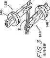
又、「先行技術」と付した図3は、ピンセット168および148を凹部181内で如何に連結するかを示したものである。これらピンセット168および148の各々において、ストリップを、タングステンワイヤを分裂させることにより形成したピンセットのようなプライヤにより支持する。このスプリットワイヤはリング146をスライドさせることにより試料に固着される。
ピンセット168を、弾性を有する片持ち梁のようなビーム162に固着して、ブラケット166により基部プレート110に装着する。凹部181内のストリップSを変換器140により移動し、ビーム162をある量だけ変位させる。この変位により、ビーム162は、その偏りの関数である復元力を生ずる。それゆえに、ビーム162の変位を測定することにより、試料S中の力即ち応力を測定することができる。このビームの変位を測定するためには、コンデンサを以下のように形成する。ビーム162の下側を第1の金属層164で覆い、基部110上に配置したブロック169を第2の金属層161で覆う。
金属層161および164は平行平板コンデンサを構成し、その容量は金属層161と164との間のギャップにより変動し、このギャップはビーム162の変位により変動し、この変位はストリップS内での1%以下の応力に比例する。これら金属層161、164を、リード2161、2164により回路(図示せず)に接続し、この回路により層の容量を電子的に(例えば、値Cのビーム162コンデンサおよび値Lの遠隔インダクタを含むLC共振回路の周波数を測定することにより)測定する。
ピンセット148の変位が、ピンセット168の変位とストリップSの伸張分との和に等しいことに注意されたい。
発明者等が提案したプロトタイプの方法は、当該技術分野において相当の進歩をもたらしたものであり、リガンドに関する新らしい種類のデータを収集することができるの新規な測定方法であった。しかしながら、試料を調整するプロトタイプの方法、および使用した応力/歪み測定装置は、種々の欠点を有するものであった。
1つの欠点は、長さが0.3乃至0.7mmしかない、非常に小さく且つもろい試料は取り扱いずらく、応力/歪み測定の際に固定しずらいということであった。
図2および図3に示したクランプ装置は、サブミリメータのオーダーで使用するには著しく不便なものである。もろいストリップは、非常に注意して取り扱う必要があった。ストリップを剥離したり、カットする調製段階は実体顕微鏡の下で行う必要があった。ストリップSをピンセットに装着するにはマイクロマニピュレータが必要であった。この工程は非常に時間を費やすものであった。
図3のプロトタイプ装置は、試料を均一に把持できないようである。即ち、ピンセットのの長さに沿う一点では他の点よりも試料を強く把持する可能性があり、これにより、把持の弱い部分が外側にスライドした場合には、試料Sの幅に亘り歪みが不均一となる。またこれらの装置は、その長さに沿って種々の点で試料を把持するようであるので、試料Sがその幅に亘る全ての点で等しい力により把持されるにもかかわらず、試料の効果的な長さを不確定即ち更に不均一なものとする恐れがある。また、ピンセットは試料Sを破断する恐れさえある。
ストリップSの把持された部分の実効的な長さは、発明者等の方法によって得られる定量データを計算する為に使用される量の1つである。従って、この定量的な結果は不均一な把持によって簡単に影響を受ける恐れがある。(本発明の理論は、以下の本発明の詳細な説明において記載する。)
試料を不均一に把持することによる悪影響は、ピンセットを高精度のものとすることによって除去することができるが、このようなピンセットは非常に高価なものであって容易に損傷を受けるものであり、仮に損傷を受けた場合にはその損傷が分からないものである。
プロトタイプの機械的な配置の他の欠点は、2組のピンセットがオフセットすることによって液体が流れだすという問題を生じることである。このピンセットの垂直方向の挿入動作および水平方向の試験動作は、フローチャンバ中にL型のスロットを必要とし、このようなスロットを有するフローチャンバは、簡単に漏れてしまうという理由で有機溶媒溶液または表面活性成分を含む水溶液のような、表面張力の小さな溶液を取り扱うことができない。凹部181で「濡れ」を起こさない液体であって、それゆえに、スロットから流出することがないものだけしか使用できない。
図2の装置のもう一つの欠点は、容量性の力変換器160を、霧、埃、および装置の測定結果に影響を与える恐れのある漂遊電界から良好に保護することができないということである。
本発明の概要
従って、本発明は、とりわけ、上述したような先行技術の欠点を克服するという目的を有する。
本発明の特徴的な目的の1つは、ストリップを試験装置に配置する場合に、ミクロ的に処理する装置又は極微細な視野を必要としないで試料ストリップを機械化学的に試験することである。
他の目的は、資料ストリップの装填に対して制御された条件を提供することにある。
第3の目的は、試料ストリップを簡単且つ迅速に装着することである。
第4の目的は、フローセル溶液の表面張力に依存しない設計を使用することにより、表面活性成分を含有する溶液と有機溶媒中にリガンドを含有する溶液とにより使用可能なフローセルを有する機械化学的な試験装置を提供することにある。
第5の目的は、湿気および霧に対して効果的な保護を行う機械化学的な試験装置および安定した力変換器を提供することにある。
第6の目的は、プロテイン又はDNA膜の横方向の弾性又は横方向の張力特性を測定することを含まない、プロテイン又はDNA膜にリガンドをバインドさせた際の変形を測定する方法を提供することにある。
従って、本発明は、プロテイン又はDNA膜の変形を測定することによってリガンドの結合を決定する方法の他に、リガンドの結合を定量的に機械化学的に測定するための方法および装置を提供することにある。
本発明は、重合体材料の試料ストリップに対する化学物質の影響を、改良した方法で定量的に測定するために設計されたものである。この装置は、一対の支持部材を含み、その各々はその一端で試料保持チップを有し、このチップは重合体材料の試料ストリップを突き刺したり、接着したりするようにしたものである。使用に際してチップにより支持された試料ストリップに力を与えるための手段を、少なくとも1個の支持部材に装着する。又、使用に際して化学物質に曝されることによって生じる試料ストリップの化学的、機械的および電気的な特性の変化を測定するための手段を試料ストリップに直接および間接的に装着する。この力は、試料ストリップを膨張または伸縮させるためにチップ間の試料ストリップの方向に対して平行に加えるかまたは維持するのが好適である。好適な測定手段は、一方の支持部材の他方の支持部材に対する移動を測定するか、あるいは一定の移動においてチップを維持するのに必要な力を測定するための手段である。1つの実施例においては、この力手段は、試料ストリップの長さを周期的に変化させるための手段を含む。
本発明による装置の好適な実施例においては、タンクのような溶液収容容器を更に設け、この溶液収容容器により支持された溶液中に試料ストリップを浸すように、試料ストリップをチップにより保持するためのメカニズムを含む。このようにして、試料ストリップを容器中の溶液に浸している間に試験することができる。他の好適な実施例の装置は、試料ストリップをチップに保持させるためのホルダを含む。この装置は試料ストリップホルダを支持部材に対して予め決定した位置に整列させ、試料ストリップをチップに装着することを容易にする。
本発明は、さらに、重合体材料の試料ストリップに対する化学物質の影響を定量的に測定するための装置を使用する方法に関するものである。この方法においては、重合材料の試料ストリップを、1対の支持部材の試料保持チップに装着して試料をチップ間で保持する。次に、試料ストリップを基準溶液に浸し、この装置によって試料ストリップに力を加える。試料ストリップの物理的(化学的、電気的、光学的、磁気的、音響学的、機械的等)特性をこの装置により測定する。次に試料ストリップを、試験すべき化学物質を含む溶液中に浸し、同一の物理的特性を再度測定する。測定した特性の変化を検出することにより、重合体材料に対する化学物質の影響を決定することができる。
好適には、チップで試料を貫通することにより、または接着剤によって試料をチップに接着することにより、重合体材料の試料ストリップをチップに取り付ける。
プロテイン又は核酸材料に対するリガンドの結合を定量的に測定するに際して、本発明による方法使用することが好適である。従って、この試料ストリップを重合したプロテイン又は核酸材料とし、その影響を測定すべき化学物質を、プロテイン又は核酸材料に対する結合力を試験すべきリガンドとすることが好適でる。
また、本発明は、リガンドの結合の際に生じる、重合したプロテインまたはDNAの膜の変形により影響を受ける物理的特徴を測定することによりリガンドのプロテイン又はDNAとの相互作用を検出するための方法に関するものである。先ず、試験すべきプロテイン又はDNAを重合させて、プロテイン又はDNAの固体試料ストリップを形成する。プロテイン又はDNAの試料ストリップを測定すべきリガンドに接触させる。プロテイン又はDNAと測定すべきリガンドとの間のいかなる相互作用をも検出するためには、ストリップをリガンドに接触させる前後で試料ストリップの物理的な特性を測定する。測定にはいかなる方法もが使用され、この測定においては、試料ストリップの重合構造が検出可能となる。ストリップをリガンドと接触させる前後での測定した特性の間のいかなる差異をも検出する場合には、これによりリガンドとプロテイン又はDNAとの相互作用が明らかとなる。
このような重合したストリップの横方向の弾性変化、または横方向の歪み特性の変化の測定を含む特定の方法は本発明者等によって以前に公表されているので、試料ストリップの物理的特性を測定するこのような手段は、本発明の方法から明らかに除外されている。ここで用語「横方向」とは、試料膜の最長の寸法(長さ)に対応した軸に沿って測定した特性を意味する。本発明の方法が本発明の新規な装置を使用する場合には、本発明の方法から除外されている横方向の弾性または横方向の歪み特性の測定を使用する方法が依然として本発明の1部分であると考えられることに注意されたい。
プロテイン又はDNAとリガンドとの相互作用を検出するのに使用することができる新規の方法の中には、横方向の弾性又は横方向の歪み特性の測定以外に以下のものを含む。プロテイン又はDNAの重合体膜を、リガンドによって影響されない第2の層に被着してバイモルフ構造を形成することができる。この第2の層は応力又は歪み感応性材料(例えば、圧電性材料)で形成することができ、又は試料ストリップとして同一のプロテイン又はDNAから形成することができ、このストリップ上では、活性重合サイトがブロックされている。リガンドによって引き起こされるプロテイン又はDNAの変形に際しては、全ての構造体が湾曲し、このような湾曲は、光学的、電気的等のいかなる好適な方法によっても測定することができる。バイモルフの変形例では、試料ストリップを歪み感応性表面に接着する。試料ストリップの変形に際しては、感応性表面の歪み又は応力の変化が誘起され、これにより既知のテンソル感応性の方法と類似した方法で電気信号を発生させることができる。
本発明の方法を実施する他の方法は、炭素粉のような微量の導電材料をプロテイン又はDNAに含ませて、電極を膜の各側に配置することである。この場合にはこの膜の導電率を、リガンドを加える前後で測定する。リガンドによって試料寸法が僅かに変動によっても、試料の導電率には大きな変化が見られる。試料の膨張により導電率が低下し、試料の収縮により導電率は上昇する。他のタイプの技術は、リガンドによって誘起される膜厚の変化、即ち膜の厚さ方向の導電率の変化、即ち膜の法線方向の変化を測定することである。この厚さの変化は、楕円偏光法またはいかなる他の光学的な方法によっても測定することができる。特に、膜の法線方向の変形(即ちその厚さ方向における変形)を測定する場合には、膜を、単分子層の場合と反対に、プロテイン分子間に分子間コンタクトができるように比較的分厚いものとするのが好適である。このような場合でさえ、プロテイン試料の寸法をミクロンオーダーに抑えることができる。又、膜の弾性および厚さの変化は、音響学的方法によっても測定することができ、これらの方法においては、固体共振子の周波数を測定することができる。又、厚さに関する差異は電極による方法によって測定することができる。電極のインピーダンスは、プロテイン分子を包む電極上の半導体性のプロテイン膜の厚さ、プロテイン分子の電荷、およびプロテイン分子の組成に対して感応するものである。電極のインピーダンスの変化によって、リガンドの結合による膜の変形を明らかにすることができる。プロテインの層を磁性体により覆う場合には、磁気センサからの距離が膜の変形に従うものとなる。
膜厚と法線方向の弾性はインデンタを使用して直接測定することができる。刻み目の深さは、プロテイン又はDNA膜の負荷または弾性の関数である。マイクロバリアント(microvariant)のインデンタによる方法は、原子間力顕微鏡の使用を伴う。電子間力顕微鏡のチップをインデンタとして使用することができる。チップに種々の負荷を与える下で得られる試料断面を比較することによって、歪みおよび弾性パラメータを別個に計算することができる。
重合したプロテイン又はDNA膜を伝搬する音波の伝搬速度を利用して変形を測定することができる。これら音波には、ピエゾ結晶表面上のレーリー波を含むことができる。試料ストリップを通過する横波又は縦波の伝搬速度は、直接、または試料の定常波の波長を検出する共振法によって測定することができる。
本発明による方法は、上述した特定の技術に限定するものではない。横方向の弾性または横方向の歪み以外の試料ストリップに関する物理的な特性の測定に対してはいかなる方法をも使用することができ、これら方法により、リガンドと相互作用させる際の試料ストリップの重合構造の変形を検出することができる。例えば、プロテイン又はDNA膜を、フィルタまたは毛管の気孔に堆積させることができる。フィルムがリガンドと相互作用する際のフィルムの膨張および収縮によって毛管を通過する溶液の流量が変化し、このパラメータを利用して膨張を精査することができる。本技術分野の当業者が本発明を知り、理解した場合には、本発明の方法の工程を規定する請求の範囲に記載されている手段を実現するために、明細書の本文に記載されている工程と同等の他の工程を考案することができることが予想される。
更に本発明は、本発明により使用することができる試料ストリップの形成方法に関するものである。1つの方法においては、補強材料を表面上に形成し、補強ストリップに接着するように、試験すべき重合材料をこの補強ストリップの少なくとも一部分を含む表面に亘って形成する。次に、重合材料とこの重合材料に被着した補強ストリップとを、表面から取り外す。このようにして調製した試料を装置のチップに装着するために、補強ストリップが設けられている部分でチップに装着される。他の方法においては、補強部材の使用するかまたは使用せずに、表面上に重合体材料を電子スプレイさせて試料ストリップを形成する。
重合体材料をプロテインまたはDNA材料とする場合には、プロテインまたはDNA分子は表面に被着させて補強部材と接触させた後に乾燥させる。従って、膜を表面に形成し、この膜は少なくとも部分的に補強材料のストリップと重なり合う。次に、膜のプロテイン又は核酸分子を重合させ、この重合させたプロテイン又は核酸材料とその下にある補強ストリップとを表面から取り外す。補強材料のストリップの表面を前処理して膜を補強材料に接着させるのが好適である。この補強材料はゼラチンとするのが好適である。
【図面の簡単な説明】
本発明の上述した目的、特徴および利点と、他の目的、特徴および利点とを、図面と共に行った本発明の実施例の詳細な説明によって、更に以下で明らかにする。
「先行技術」と付した図1は、ストリップを準備する先行技術の処理を線図的に示したものである。
「先行技術」と付した図2は、先行技術の装置の斜視図を示したものである。
「先行技術」と付した図3は、先行技術のピンセットの斜視図を示したものである。
図4は、本発明による装置の斜視図を示したものである。
図5は、図4の線V−Vに沿って切った部分的な断面図である。
図6は、基部の斜視図である。
図7は、ホルダの斜視図である。
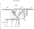
図8は、フローセルの断面図を示したものである。
図9A乃至図9Dは、チップとホルダの線図的な斜視図であり、チップをストリップに装着する操作を示したものである。
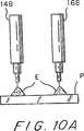
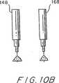
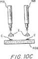
図10A乃至図10Dは、チップをストリップに装着する代替的な操作を示した線図的な断面図である。
図11A乃至図11Dは、ストリップを準備する操作を示した線図的な断面図である。
図12は、種々のグルコース濃度に対応したヘキソキナーゼ試料の等方性応力および弾性係数の変化の測定結果を示したものである。
図13は、ヘキソキナーゼプロテイン膜中のグルコースに対する解離定数の測定結果を示したものである。
図14は、メチル−α−D−マンノピラノシド(mannopyranoside)(MP)の種々の濃度、グルコース溶液(Clc)およびバッファ溶液からの二価の陽イオンの除去に対応するコンカナバリン(concanavalin)A試料の等方性応力の変化の測定結果を示したものである。
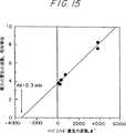
図15は、カバリンAプロテイン膜中のメチル−α−D−マノピラノシド(mannopyranoside)(MP)の解離定数の測定結果を示したものである。
図16は、制御試料および48時間10-6Mのビオチン溶液中に予め曝した試料中のビオチン溶液に対するアビジン膜の反応を試験する手順を示したものである。
図17は、図15に示したように測定した4×10⁻⁴Mに応じたアビジン膜の等方性張力および弾性係数における相対的な変化を示したものである。試料は48時間種々の濃度のビオチンに予め曝した。
図18は、測定装置を線図的に示したものである。
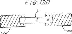
図19A乃至図19Bは、下方から試料ストリップに被着した構成部材を支持するチップの側面図(図19A)および平面図(図19B)である。
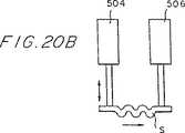
図20A乃至図20Dは、音波の伝達速度から変形および弾性変化を測定するための波動型の方法を線図的に示したものである。
図21は、試料ストリップの導電率により試料ストリップの変形を測定する方法を線図的に示したものである。
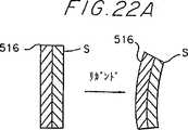
図22A乃至図22Cは、リガンドが引き起こした変形によるバイモルの曲げを測定するためバイモル構造およびその実施例を線図的に示したものである。
図23は、リガンドが引き起こした変化をテンソル抵抗性のセンサによって測定する歪み感応構造を線図的に示したものである。
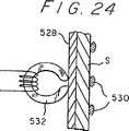
図24は、リガンドによる膜厚の変化を測定する磁気方法を線図的に示したものである。
図25は、リガンドによって引き起こされた膜厚および弾性の変化を直接測定するためのインデンタ法を線図的に示したものである。
図26は、フローチャネル中のプロテイン膜の変形によりチャネルを通る液体の流速が変化するようにした方法を線図的に示したものである。
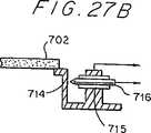
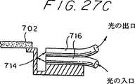
図27A乃至図27Dは、機械技術的な試験装置のチップタイプの構造を線図的に示したものであり、この装置においては、試料膜、試料ホルダおよび力変換器が、着脱可能で廃棄可能な小型のユニット(図27A)として結合されている。図27B乃至図27Dは、力または変位センサの可能な構造を線図的に示したものである。トンネル電流センサ内では、可撓性を有する片持ち梁の振れを片持ち梁と点状接点との間のトンネル電流の変化によって測定する(図27B)。図27Cに示したような片持ち梁の振れによって引き起こされた光の偏向および干渉、または図27Dで示した片持ち梁表面上の導電層の抵抗の変化も、力センサとして使用することができる。
図28Aおよび図28Bは、試料膜の電気コンダクタンスを測定するための方法を線図的に示したものである。
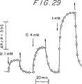
図29は、三斜晶のリゾチームから調製した鶏の卵形のホワイトリゾチーム膜の抵抗の、リガンドが引き起こした変化を示したものである。下向きの矢印は、図示した濃度の2、5−ジニトロフェニル溶液が加えられた時点を示したものである。上向きの矢印は、0.1MのNaClを含み、pH4.6の洗浄溶液を加えた時点を示したものである。
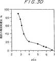
図30は、カルシウムイオンの結合に応答するたらのアモルファスパーバルブミン膜(amorphous cod parnalbumin film)の抵抗の変化を示したものである。測定は、0.1MのNaClを含むpH6.0のCa−EDTAバッファ中で行った。
図31は、誘電性のスクリーンの開口を介して帯電粒子の電子スプレイの堆積に関する静電気レンズの効果を線図的に示したものである。
図32は、試料膜の作製および取り外し操作を線図的に示したものである。
図33Aおよび図33Bは、カバリンA(図33A)と馬の肝臓のアルコール脱水素酵素とをの電子スプレイにより成膜した膜を示したものである。プロテイン膜は、マスクに形成した1個の矩形開口(0.8×0.2mm)を介してA1電極上に堆積した導電ポリマの補助膜上に堆積した。
図34Aおよび図34Bは、ヒトヘモグロビンの電子スプレイ堆積膜の多孔質性の構造(図34Aに乾式堆積した後に走査型顕微鏡によって得られた膜表面の像)と、膜を「燃焼」した結果としての膜構造の変化(湿った大気中に曝した後の同一の膜の構造を示した図34Bの像)とを示したものである。
好適な実施例の詳細な説明
本発明による方法の好適な実施例においては、DNAまたはプロテイン溶液から重合体材料のストリップを調製するものであり、このストリップは応力/歪み試験または機械的コンプライアンス試験に対して機械的に好適であり、このストリップの端部には機械的な補強用細条が設けられている。各ストリップの幅方向に延在する補強用細条を設けることにより、ストリップの取り扱いが容易となり、ストリップの種々の長さ方向に延在する部分に沿って不均一な伸びが生じるのが防止される。
このストリップを形成する好適な方法の一つでは、ガラス表面上にプラスティクの補強用細条を等間隔に互いに平行なアレイ状に形成し、ガラス表面と補強用細条とをプロテインまたはDNA溶液により濡らし、この溶液を乾燥し、プロテインまたはDNAを重合させる。その後、補強用細条を、その長さ方向に切断する。この方法に得られる個々の試料ストリップの両端部は、補強用細条の幅の半分の位置で切られたものとなる。
ストリップを形成する他の好適な方法では、表面に補強用細条が設けられた表面に電子スプレイによってプロテインまたはDNAを堆積することができる。
上述した法により調製されたストリップと共に使用される好適な装置は、それぞれが最下端に試料保持チップを有する下方に向け延在する一対の支持構成部材を有するものである。一方の支持構成部材を力変換器に固着し、他方を移動または変位変換器に固着する。この支持構成部材チップは、溶液を保持する容器または樋状の凹部内に侵入するように降下するので、いかなる液体をも使用することができる。この支持構成部材は、この装置の垂直方向に移動可能な変換器ハウジング上で支持され、このハウジングは基部に固着された精密なトラック上で上下に移動することができる。あるいは又、この変換器を固定配置とし、凹部を移動可能とすることができる。オペレータが変換器ハウジングを上下に移動させることによって支持構成部材を凹部内に侵入させたり凹部から引き上げたりすることができる。試料ホルダを使用して装置に試料を装填するのが好適である。この試料ホルダは、基部に対してホルダを正確に配置するための正確な位置決め表面を含むジグとする。試料ホルダと変換器ハウジングとの両方を基部に対して正確に保持することができるので、変換器ハウジングを繰り返し降下させた場合、支持構成部材のチップは試料ホルダに保持された試料上の常に同一の2点へ、数ミクロンの精度で繰り返し落下させることができる。
本発明による装置を使用する好適な方法では、試料ホルダを基部に配置し、支持構成部材がホルダと接触してマークを形成するまで変換器ハウジングを降下させるようにしている。この場合には支持構成部材チップが正確な位置でストリップに接触するような位置にあるマークと重なるように試料ストリップを容易に配置することができる。次に、変換器ハウジングを再び降下させ、チップが試料ホルダの頂面にあるマーク上に配置されたストリップと接触してこのストリップを把持させる。この把持は、尖鋭なチップ先端をストリップに貫通させ、内部を減圧した毛細管(チップ)の先端に試料ストリップを吸引し、ストリップをチップに接着することを含む幾つかの方法により実施することができる。この後者の方法では、チップの先端は平坦として、吸引したり接着したりできるようにするのが好適である。
あるいは又、図19Aおよび図19Bに示すように、支持部材(500)のチップを試料ストリップの下側から接着することもできる。
ストリップには補強部材を介してチップが貫通するようにするのが好適であるが、この場合には、チップによる力は補強部材によって分散される。また、接着剤を使用する場合にも、チップを補強部材上またはその近傍で接着するのが好適である。
試料ストリップを支持部材間でしっかりと固着した後に、変換器ハウジングを持ち上げ、試料ホルダを取り外し、試料ストリップを降下させて凹部内に侵入させし、基準溶液(バッファ溶液または分析すべきリガンド以外は試験溶液またはこのようなリガンドの存在が疑わしい溶液と同様の調整用と呼ばれるいかなる容液)に浸す。この基準溶液中で、ストリップを静的歪み(変位)変換器により一定の長さに引き延ばし、次に一定の等方性張力が生じるまでストリップを緩める。ストリップを緩めた後に、フローチャンバ中の基準溶液を、ストリップを構成しているプロテインをバインドすることができるように試験された1つ以上の化学物質を含む試験溶液と置き換える。等方性の張力および/または弾性係数の変化はバインディングの程度を表わすものである。
金属や他の材料の機械的特性を試験する通常の方法(試料を取付け、センサを駆動し、測定を行う等)と比較して、本発明によるプロテイン膜の試験は、基本的には、膜を包囲する溶液が基準溶液からリガンドを含む溶液に変化するときのプロテイン膜の機械的パラメータの変化を検出ものである。この全処理は、力センサにより行われる。単一の変位変換器によって、試料を一定の長さに引き延ばすことと、その長さを正弦波状に時間と共に少量だけ変化させてコンプライアンス試験を行うこととの両方がなされる。
あるいは又、2つの長さ変換器を設けることもできる。試料を振動変形させる一方の変換器を、ある期間オンとし、静的な変形を行う他方の変換器を、試験期間中駆動させないでおく。この場合、静的な変換器を使用して、例えば試料を引き延ばして試験の準備をする。
本発明の機械化学的装置を使用する本発明の方法を最良に実施するには、特に試料部材をプロテインまたはDNAとする場合、以下の要件を付加される。
1.試験すべき試料中の分子を重合するか、または物理的に接触させる。
2.試料の少なくとも1つの方向の寸法ををマクロ分子よりも大きくする。
3.試料の少なくとも1つの方向の寸法をほぼミクロンのオーダとする。1つの方向の寸法を小さく(薄く)した場合には、この試料は膜と言われる。2つまたはすべて即ち3つの方向の寸法を小さくした場合には、試料は繊維またはビーズと言われる。
4.この装置により試料を少なくとも一点で保持する。
5.装置に対して試料を単独でまたはホルダと共に交換可能とする。
6.装置には、試料を包囲する気体または液体の組成を変化させるための手段を含む。
要件1または2は共に、本発明の技術と固定化されたプロテインを使用する他の技術とを区別するものである。例えば、BIAコア装置(ファルマシア(Pharmacia))では、プロテインは金の表面に固定されるが、互いにバインドすることはない。
力センサと、変位センサとの区別は、力センサが試料のコンプライアンスよりも相当小さいコンプライアンスを有する一方、変位センサのコンプライアンスは試料のコンプライアンスよりもかなり大きいということである。同様のことが変換器についても当てはまる。これらの変換器および/またはセンサは、力をセットおよび/または測定する手段であり、変位をセットおよび/または測定する手段である。同じ装置を用いてセットまたは固定と、測定とを行うことができる。本発明においては、いかなるタイプの力センサ(変換器)、およびいかなるタイプの変位センサ(変換器)を使用することができる。
本発明は、一定の応力の下で歪みを動的に測定したり、一定の歪みの下で応力を動的に測定しようとするものである。先行技術の方法とは違って、また本発明では力を一定に保ち、歪みを測定することができる。即ち、一定の応力または力Fで試料を保持し、歪みを変化させることができる。先ず、試料に与える力を緩め、次に、力を周期的に変化させて伸びを測定することができる。1つの装置をこれらの態様の測定の両方に使用することができる。
本発明の装置では、試験以前に試料ストリップを伸張することが好適であることは勿論である。これには2つの理由がある。1つは、ストリップを伸張する場合に試験をより高感度とすることであり、もう一つはストリップの歪みまたは伸びが負に落ちこんだ場合には応力−歪み関係が覆されることである。ストリップはフックの法則に従うかまたはこの法則に近似して撓み、この撓みが終結する(ストリップが非常に厚くまたは非常に短くなるまでは、各ストリップにより試験の感度が著しく低減しまたは損なわれる。)。一旦ストリップが張力を受けない状態になると、バネ定数の測定が不可能となる。
本発明の好適な実施例においては、変位変換器がストリップを伸張する手段をも構成する。
また、本発明では弾性−−力と長さとの関係−−を測定を使用して、試料ストリップのバインドを決定することにも注意すべきである。本発明は、当然、試料ストリップのどの方向の寸法をも測定する必要はなく、本発明の好適な態様においては、ストリップの長さを一定とするか、または予め決定したパターンにしたがって僅かに変化させる。この長さは独立変数である。従属する変数または測定される変数は力である。
本発明による測定の他の態様においては、ストリップを、同じ2つの量を用いて伸張する間に弾性を測定するが、力が既知の場合には変形または変位が測定される量となる。この他の態様においてさえも、測定量、寸法はリガンドのバインディングを直接測定したことにはならない。ディメンジョンと力との比によってのみ最終的な結果が得られる。ストリップに力を加える付勢手段は、ばねの他に能動変換器/センサをも含む。ストリップの一端をこのようなスプリンブに固着した場合には、この端部の変位は伸張力に比例し、この変位は適当なセンサによって測定することができる。
力を試料ストリップに加える手段の特定の実施例として種々の変換器を開示するが、装置のチップによって支持された試料ストリップに力を加えるのは、どのような手段をも使用できることを理解すべきである。例えばストリップに力を付与して伸張させた後は、或いは少なくともストリップが完全に伸びきって変形しなくなった状態に維持した後は、ストリップの他の特性を測定するためにストリップに他の作用を与えることができ、この結果化学物質がストリップに与える影響を定量的に測定することができる。従って、例えば電気エネルギーまたは音響エネルギーをストリップに加えることができる。同様に、この測定手段は弾性だけでなく、試料に加えた動作に依存する化学的、機械的または電気的特性をも測定することができる。このようにして、化学物質を作用する前後で、電気信号または音波が試料を通過する態様を測定することができる。例えば、膜を通過する音波の伝搬速度の変化を使用して膜の弾性に関する変形および変化を測定することにより、リガンドのバインディングを測定することができる(図20A乃至20D)。弾性の変形および変化を測定するためのこれらの波長方法には、波発生器(504)によって生じ且つ波センサ(506)によって測定されたレーリー波の速度のバリエーションによって表示することができる圧電結晶すなわちピエゾクリスタル(502)(図20A)の表面に形成された例えばプロテイン膜のような試料ストリップの質量および弾性の、リガンドが引き起こした変化が含まれる。試料ストリップを横方向に通過する波(図20B)および縦方向に通過する波(図20C)の伝搬速度は、リガンドのバインディングを測定する為に利用することができ、直接的にまたは試料中の定常波の長さを整合させる共振法(図20D)により測定することができる。
本発明の技術分野における既知の位相法、衝撃(インパルス)法および共振法を使用して、これら全ての波形構造法をに関する波の伝搬速度を測定することができる。波発生器504および試料ストリップS中の波の伝搬速度を測定する波センサ506を、図20Bおよび図20Cに示した。図20Cにおいては、ピエゾクリスタル502を試料ストリップSの両端に連結するが、図20Dにおいては、ピエゾクリスタル502は、定常波508を測定するように試料ストリップSの一端で配置されているだけであり、試料ストリップSの他端は剛固な壁510に固着されている。
図21に示した他の実施例では、試験すべきポリマー材料の試料ストリップ中に、炭素粉のような導電性の粒子514を含ませる。試料ストリップSの導電率を、電極512間で測定するが、図21の下側部分で示したような、リガンドよって引き起こされた試料の僅かな寸法変化(例えば膨張)によって、導電粒子間の接触が失われる場合には試料の導電率に大きな変化が生じる。電極間の試料導電率を測定する手段が必要なだけであるので、これが最も容易なプロテインセンサである。1つの実施例においては、本発明による装置のチップを電極として使用することもできる。
他の実施例では、2層構造より成るバイモル構造(図22A)とするが、そのうちの1層は試料ストリップの層Sであり、もう一つの層516はリガンドによって影響されず、歪みまたは応力に感応する材料(例えばピエゾ電気)、またはリガンドをバインドすることができる能力が変成によってブロックされる同様の重合プロテインまたはDNAで構成する。こおようなバイモルをリガンド溶液に曝した場合には、、試料ストリップ層Sの変形によりバイモルフは湾曲する。図22Aにおいては、試料ストリップ層Sの収縮によりバイモル構造の曲げが生じ、このバイモルの曲げはいかなる好適な方法、即ち簡潔で差動的なレスポンスを利点を有する光学的、電気的な方法等により測定することができる。図22Bおよび図22は、バイモル構造Bの変形を、光源518および位置感知光検出器520(図22B)によって、または距離センサ522(図22C)によって光学的に検出することができることを示したものである。また、試料ストリップSを歪み感知表面524(図23)上に堆積した改良型のバイモルのような、歪み感知構造では、リガンドにより誘起される歪み(応力)の変化を、既知のテンソル抵抗センサと同様に、電気信号をセンサ526に発生させることができる。このような改良型のバイモル上での試料調製は容易であり、多量生産することができる。
試料を支持体上に膜として堆積する場合には、リガンドによって引き起こされる膜厚および/または硬さの変化を、(1)膨張/収縮によって層の厚さと屈折率との両方の変化が生じる偏光分析法または干渉分光法により、(2)石英結晶のような固体共振子の共振周波数の変化を、膜が変形(例えば膨張)する際の膜厚および弾性の変化に応答して測定する音響学的な方法により、(3)試料膜を導電表面に堆積し、膜の膨張、帯電したリガンドの結合による反対極性のイオンの濃度の変化、試料膜のイオン導電率の変化等よる実効的な誘電率の変化により生じ得る電極のインピーダンスの変化を利用してリガンドが結合する際の膜の膨張を検出する電極インピーダンス法により、(4)フォイル層528に堆積した試料膜層Sを磁気粒子530で覆い、磁気ヘッド532から磁気粒子530までの距離を測定することによりリガンドの結合の際の膜厚の変化を測定する磁気法(図24)により、および(5)図25に示すように、原子間力顕微鏡のチップのようなインデンタチップ534が基板536上の位置から試料膜S上の位置まで移動させて膜厚および膜の硬さをこのチップにより直接測定し、刻み目の深さを試料膜の負荷と弾性との関数として測定するインデンタ法により測定することができる。このインデンタ法のインデンタチップにより加えられた種々の力Fの下で膜厚を測定することにより、膜の弾性を決定することができる。膜のコンプライアンスが大きななれば大きくなるほど、インデンタチップの下でよりフィルムが変形し、測定される膜厚は薄くなる。このインデンタ法により、種々の試料を同時に検出することができ、試料を走査する効率が高くなるという利点がもたらされる。(先行技術による横方向の測定に対応して)縦方向の変形を測定することを含むこれらの方法のすべては、プロテインまたはDNAの試料の寸法を、単分子層よりも厚くするのが好適であるが、ミクロンオーダーまで減少させることができるという利点を有する。
更に他の実施例においては、図26に示すように、リガンドの結合を、チャネル、即ち毛管やフィルタ中の気孔等を流れる液体の関数として測定することができる。リガンドに応じてチャネル壁540に堆積した試料膜Sの変形(膨張または収縮)により、チャネルを通過する液体または気体の流量を変調し、この流量パラメータを利用して試料膜の変形を測定することができる。
図28Aおよび図28Bは、試料膜710の電気的コンダクタンスの変化を測定することによりリガンドと相互作用する際の試料膜の変形を検出する方法を、各々断面図、平面図で示したものである。試料膜710を電極の端に接着し、絶縁物704で被覆されたワイヤ706、例えば白金ワイヤと接触させる。ワイヤにははんだスポット702により導線700を接続する。プロテイン膜の周縁を絶縁性の接着剤層で覆い、試料膜をリガンドを含む溶液のような溶液中に浸漬したときにも電流の短絡が生じないようにして、試料膜を通して導電率を測定する回路を構成する。
図27Aに線図的に示すように、力変換器、力センサおよび試料膜(例えばプロテイン)を単一ユニットとして組み込むことができ、この場合には、使い捨てユニットとして使用することさえできるこのような一体のユニットを簡単に交換することができるということが1つの利点である。図27Aにおいては、着脱可能なチップ700を、試料膜702、力変換器704(力センサ)、および膜に変形を生じさせる手段706で構成し、この手段を移動可能な部分とする。この着脱可能なチップ700を、移動可能な部分706を移動させる手段710を有する測定ユニット708内に配置する。膜の変形は基部712に対して移動可能な部分706をシフトさせることによって達成される。
図27Aに示した着脱可能なチップ700に使用できる1つのタイプの力センサを図27Bに示した。このセンサにおいては、トンネリング電流の変化を利用して、負荷を与えた状態での試料膜702に固着した可撓性を有する片持ち梁714の変形を測定する。トンネリングは、絶縁体715を有する第1の電極716と、第2の電極と間の小さなギャップ(ほぼ0.1乃至2nm)を介して電子を運搬する処理であり、第2の電極も片持ち梁であって、そのトンネリング電流はギャップに著しく依存し、その値から、較正したばね(片持ち梁)の変形として力を測定するものである。
着脱式で機械化学的なチップに用いる他のタイプの力変換器は、光ファイバ716(図27C)を使用することによるような、反射光の強度または方向の変化を光検出器で検出することにより、片持ち梁714の変形を測定する。図27Dは、さらに他のタイプの力変換器を示したものであり、この変換器においては、片持ち梁の両サイドをテンソル抵抗718のような変形−感知コーティングにより覆い、片持ち梁の曲げに応じて生じる導電性に関する変化を利用して力を測定する。
また、試料を装置に取り付ける方法としては、本発明の範囲内では、接着、ピン止めに加えて、種々の方法がある。例えば、比較的低温で固化する金属によって形成したホットメタル接着(熱接着剤)を使用することができる。また、磁界中で固化する磁性液体を使用して試料を接着することができる(磁気接着剤)。更に他の例においては、大気圧を利用して、試料を毛細管の端部に吸着することができる。
以下の詳細な説明では、先ず本発明による試験に使用する装置を記載し、次に、試料(プロテインまたはDNA材料)の調製を記載し、続いて(リガンドを含む溶液中に試料を浸す結果としての試料ストリップの機械的な特性の変化を測定する装置を使用する)試験方法を記載し、最後に本発明の結果を論ずる。
本発明による装置の外観を、図4に示した。この図は、垂直方向のトラック300に設けた変換器ハウジング100に対して上下にスライドする基部200を含む。或いは又、このハウジングをスライド可能としても良い。試料ホルダ400は、基部の上面に設けた溶液凹部210の上側に配置することができる。
試料ホルダ400は、基部200の上面に形成した窪み240に対してホルダ400を挿脱自在にスライドさせるためのハンドル415を含む。この窪み240はホルダ400をがたなく、しかし密着しないように受け入れるような寸法とする。このホルダを窪み240に対して挿脱する場合にも、基部200に対して繰り返し決まった位置に配置することができるようにすべきである。ばね241および242によって、図4に示すように下側および右側にホルダ400を押して弛むことがないようにする。(図6は下側に押しつけるばね242の他の実施例を示したものである。)これにより、ホルダ400を窪み240に挿入する場合はいつでも数ミクロンの精度で正確に同じ位置にくるようになると考えられる。このような精度は、従来のジグを使用した技術によって達成することができる。図示した位置決め装置の他に、窪み240内のホルダを正確且つ繰り返して配置することができるいかなる従来の位置決め装置を用いても良い。
ホルダ400の上面には試料支持パッド408を接着するのが好適である。
図4および図5は、変換器ハウジング100を示したものであり、このハウジングは図2の先行技術の装置に対して機能上類似するものである。変換器ハウジング100の最下部から、図4および図5ではアームと表現するのがより適切な支持部材148および168が基部200に規定された試料スペースに向けて突出している。この試料スペースは窪み240の一部分を含み、その真下に配置された溶液凹部210も含む。これらアーム148および168は、試料を試験するために凹部210に移動することができる。
変換器ハウジング100(または基部200)は、トラック300、好適には精度の高い光学的なグレードのトラックに沿って垂直方向に移動可能である。この変換器ハウジング100はばね310によって上方に偏倚されており、このばねは回転可能な偏心カム312に固着されている。このカム312をハンドル314によって回転する場合には、変換器ハウジングが上下に移動し、アーム148および168のチップを試料ホルダまたは凹部210へと移動させることができる。あるいは又、ハウジング100を上げ下げするための自動機構を設けることもでき、この機構には位置センサとコンピュータで制御されたサーボ機構とを設けることができる。
ハウジング100の下方への移動は、ハウジング100の下側部分から延在するフィンガ111および112により制限される。ハウジング100を完全に下側まで押し下げる場合には、より長いフィンガ111が開口211に挿入し、このフィンアガ111が開口211の底に達したときにハウジングは停止する。ホルダ400が窪み240内にある場合には、フィンガ111がホルダに上述した開口と整列するように形成された開口411を通過する。しかしながら、ホルダ400がその位置にある場合には、フィンガ111は底に達することができない。その理由は短い方のフィンガ112が試料ホルダ400上の停止板412に突き当たるからである。従って、フィンガ111、112が窪み240から抜け出て試料ホルダ400を挿入できるまでハウジング100を上昇させることができる。また、ホルダ400が所定の位置にある場合には、ハウジングを予め決められた中間の位置まで下げることができ、ホルダ400を窪み240から取り除いてある場合にはホルダを最下部の位置まで下げることができる。この中間位置は試料上にアーム148、168のチップを取り付けるための位置であって、最下部の位置は凹部210内に保持されている試料について試験を行うための位置である。
フィンガ111および開口211は、窪み240内でホルダ400を正確に位置決めするための他の位置決め装置と置き換えるかまたはその機能を向上させるための位置決め装置として作用させることもできる。即ち、ホルダ400をばね241、242によってフィンガ111に対して保持することができる場合があてはまる。フィンガ111はハウジング100に固定されているという利点を有するので、これらフィンガは、基部200のいかなる部分よりもアーム148、168に対して正確に配置される。基部200はトラック300の遊びと等しい距離だけハウジング100に対して移動する。
図8は凹部(即ちフローセル)210を、基部200から取り外した状態を示すものである。図8の右側に示した注入チューブ217により溶液を凹部に注入する。より高位置に配置したチューブ219によって余分な溶液を除去する。凹部の内側表面を撥水性とすることが好適である。凹部210は、図示すようにミドルプレート216と2個のエンドプレート214とから形成することができる。或いは又この凹部は、射出成形あるいは密実なブロックをミリングすることにより形成することもできる。凹部は透明または半透明の材料で形成するのが好適である。図4および6に示すように、凹部210は下から、基部200に組み込まれ、拡大レンズ又は収束レンズ290を含む光学システムを介して照明すうることができる。このレンズ290は種々の外部光源(図示せず)に合わせて調整することができる。
基部200、従って凹部210の温度を一定に保つために、基部200には、液体が基部を通って循環するための内部導管および外部連結部分250を含ませることができる。
図5は、変換器を含む変換器ハウジングの一部と、凹部210とを示す断面図である。アーム148および168により、溶液L中のストリップSを保持する。図2に示すように、アーム148、168は各変換器から延在している。
変位変換器140は、電圧に応じて湾曲する素子、好適には石英ピエゾ電気バイモルを含む。この変換器140を、好適には寸法安定性の点で石英で形成されているプレート105上に配置する。図5に示すようにアーム148の先端を左右に動かせるようにプレートは調整可能とする。プレート106の内側に固着された枢軸195(好適には、石英プリズムの尖端)の回りにプレート105を枢着する。このプレート105は、第2の石英プレート106に設けた溝付き開口すなわち取り付け部と係合するネジ溝付シャフト191によって枢軸195の回りに回転可能であり、第2のプレートはハウジング100に固定する。シャフト191に取り付けたノブ196を回転させることにより、アーム148を前後に移動することができる。
力変換器160は、石英で形成するのが好適な弾性部材162を具えており、この弾性部材を金属層164でコーティングし、これを導線2164に接続する。この金属層164に近接し且つ平行に金属層161を設けてコンデンサを形成する。このコンデンサの容量はこれら2つの層161、164の間の距離によって変化するが、この間隔はアーム168の先端に作用する力により変化し、この力によって弾性部材162が移動する。腐食を防止するためにこれら金属層161、164を金とするのが好適である。
この容量−力変換器160は、これに相当する(力のスケール、精度および安定性に関して)他の変換器で置き換えることができる。上記条件を満足するものであれば、いかなる他の物理的なメカニズムを基礎とするいかなる他のタイプの変換器をも、容量−力変換器の代替品として使用することができる。
この変換器の周りの漂遊電界を減少させるために、全ての内側の部材を金属膜、好適には銀で覆い、ファラデイシールドを形成する。湿気に対して感応性が高い力変換器160を他のシールドボックス107によって包囲する。層164は、プレートの金属ライニングと同一の電位に接続することができる。又ハウジング100を金属化して別の電界遮蔽を構成することも好適である。リード2161および2164を電気回路199に結合する。
この電気回路をハウジング100内に配置する場合には、このハウジング100を全測定ユニットとし、このハウジングをディスプレイデバイス、コンピュータ等に結合してその機能を増大させることができる。また本発明によれば、変換器のみを含む測定ユニットとし、その他の電気部品は他の場所に配置することもできる。
漂遊電界と同様に、湿気が容量に影響を与える恐れがあるので、乾燥したクリーンな空気をボックス107に送り込む。リード2164にはその長さの一部に亘り、空気を吹き込むために使用される金属パイプを具えるのが好適である。
好適な石英構造によって、機械構成部材の寸法の変化によるエラーを除去することができる(石英の熱膨張係数は非常に低いものである。)
構成部材162を剛固なものとすればするほど、金層161、164間の距離の変化が小さくなって、容量の変化が小さくなり、変換器の精度が高くなることは間違いない。好適には、試料ストリップをアーム148、168間で伸張させる場合にアーム168がほんの少しだけ移動するように、力変換器160の弾性部材162を剛固にする。アーム168の移動が試料ストリップの伸張よりも相当小さい場合には、構成部材162の移動に対する補正は必要とされない。
他の変形例の構造では、弾性アーム162とバイモルを単一部材に組み合わせることであり、この構造ではコンデンサ構成部材とバイモル構成部材の両方として弾性部材に1つの金属層を使用したものである。この構造においては、一方のアームを移動可能として、他方のアームをハウジング100に固定する。このような構造により負荷を与えた状態における弾性部材の移動を容易に較正することができる。
図18は、ばね702で吊るして配置し、ダッシュポット70で制動した測定ユニット即ちハウジング100を示したものである。ばねの振動をアイソレートするための層を三層設けることが好適である。エディー効果型の磁気ダンパのようないかなる好適なダンパをも使用することができる。シールド706は、熱シールド、電磁気シールドまたは他の種類のシールドとして使用できる。本発明によれば、必要に応じてリガンド溶液およびバッファ溶液を吸い上げるためのポンプシステム710を使用することができ、また恒温システム720を使用することもできる。ハウジング100内の変換器140、160および/またはいかなる電気部品をもコンピュータ730に結合することができる。
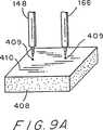
図9A乃至図9Dは、図4と組み合わせて、アーム148、168に試料ストリップSを装着する方法の1つを示したものである。
図9Aは、試料ホルダ400の上側表面に装着した支持パッド408の位置を示したものであり、試料ホルダ400を窪み240に装着した後の状態である(図4参照)。試料支持パッド408は、好適には、発泡プラスティック(例えばスチロフォーム(Styrofoam))のような比較的柔らかい材料で形成し、容易に窪んでその凹みが容易に分かるアルミニウムフォイルのような材料410で覆う。
フィンガ112がストッププレート412に対して停止するまでハンドル314を操作してアーム148、168の鋭利なチップをフォイルにまで下方に移動する(図4参照)。ハウジング100のこの中間位置においては、チップが材料410を突き刺して、(円409によって象徴的に示した)刺し跡を残す。
次にハウジングを上昇させ、ホルダ400を窪み240から取り除く。次に、図9Bに示すように、試料ストリップSを、2個の刺し跡409を覆う所定の位置で支持パッド408まで下方に移動する。
図9Cは、ホルダ400を窪み240に再び装着し後に(図4)、チップを試料ストリップSまで下方に移動させることを示したものである。この鋭利なチップがストリップSを突き刺す。
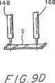
図9Dは、ハウジング100を再び上昇させた場合を示したものである。このようにしてアーム148、168に突き刺さった試料ストリップSを、支持パッド408およびハウジング100から取り外すことができる。このストリップは、溶液中での機械化学的試験のために凹部210まで下方に移動できる準備状態となっている。
図10A乃至図10Dは、(図9A乃至図9Dのようには)ピンで止めることのできない程度に柔らかい試料ストリップに好適な他の試料ストリップの装着方法を示したものである。図10Aにおいては、チップをプラスチックのシートまたはプレートPを極く僅か突き刺すのに十分ななだけ下方に移動する。エポキシのようなポリマのマイクロドロップレット(微小滴)Eを各チップ上に堆積させて配置し、固める。プレートPは、エポキシまたは他の接着剤が被着しないテフロンのような適当な材料で作る。これにより、図10Bに示すようにプレートPを取り除くことができる。チップは図10Bに示すように僅かに突き出しており、チップを支持パッド408まで下方に移動させることにより刺し跡を形成するようにする。この場合にはシアノアクリレート(例えばロクタイト(Loctite))のような接着剤を図10Cに示すように、各刺し跡に付ける。次に、チップを迅速に下方に移動して次に上方に移動する。この結果、重合時間が短いことによりチップはシアノアクリレートで濡れるが接着はされない。最後に、図10Dに示すように、試料Sを、図9に関連して上述したように刺し跡を覆うように配置する。チップを試料Sまで下方に移動して数秒保持した場合には、このストリップを接着剤CによってエポキシのマイクロドロップレットEに接着し、広い幅にわたって接着が得られる。
接着の際にプロテイン試料を損傷させないようにするためには、この処理中に試料ストリップに湿気を帯びさせる必要がある。これは、水またはバッファ溶液を使用した迅速で巧みな処理によるか、あるいはプロテイン試料を具える中間のホルダに10%の砂糖またはグリセリン溶液を加えることによるかのどちらかにより達成される。接着方法を用いる際には、試料を5乃至10分間支持してシアノアクリル酸塩の重合化を達成できる。試料を中間ホルダの表面から除去する前に、水滴を試料の上に垂らして試料ストリップを中間ホルダの表面から簡単に除去することができる。
図11A乃至図11Dは、端部が補強されたストリップSを調製するための本発明による方法を示したものである。図11の断面図では、補強ストリップPは、ガラス、プラスティック、又表面が滑らかとなる他の材料に亘っていっぱいに広げられている。この場合ストリップPとベースBとはプロテインまたはDNAを含む溶液によって湿っている。図1に示した先行技術の方法のように、この溶液を、真空乾燥し、交差結合し、場合によって洗浄する。これらの予備的な処理を終えた後に、補強ストリップPを図11Bに示すようにストリップS用のプロテイン又はDNA材料の膜で覆う。次にナイフKを使用して図11Cに示すように各補強ストリップを長さ方向に分割して1つのストリップPから2つのストリップP2を形成する。この後、必要であれば、ストリップの幅方向(図示せず)の長さを揃える。最後に、できあがったストリップSを図11Dに示すようにナイフKで剥がす。
補強ストリップP用に好適な材料は、焼いたゼラチンである。このストリップをベースB上に、好適にはフォトリソグラフィによって形成する。ニクロム酸アンモニウムを付加することによって感光性が得られるゼラチンを使用する。空気に晒していないゼラチンを分解した後、残りのストリップを2時間180℃でオーブンで焼く。基板となるベースBの表面を、最終的には減圧下で20秒のプラズマ放電に曝し、プロテイン層を補強ストリップPに強力に接着することができる。
本発明は、溶液を乾燥させることにより形成した試料ストリップのみならず、他の方法によって形成された試料でも良く、また形状に関しても偏平な帯状またはストリップ状以外の形状とすることもできる。また本発明は、リガンドの結合に対する試験をすべき1つのプロテインまたは他の物質から成るかまたはこれを含む2つの表面層と、リガンド溶液に曝されない他の物質の内側層とを具えるサンドイッチ構造の試料をも含むものである。
プロテインまたはヌクレイン酸分子に対するリガンドの結合を測定するのに使用する試料ストリップ(膜)を調製するもう一つの好適な方法に、電子スプレイ法(ES)があるが、この方法に関しては、液体または溶液の静電気による微粒子化を使用して、表面に堆積する帯電したマイクロドロップレットまたは帯電したイオンが得られる。堆積すべき物質の溶液または液体を毛細管に流し込み、高電圧を印加して液体または溶液を不安定にし、次にこの液体または溶液を、典型的には直径0.5乃至2ミクロンの少し帯電したドロップレットに分散する。静電気の斥力によって、毛細管チップからこれ等の帯電したマイクロドロップレットが迅速に移動し、基板表面に向かう移動中に、溶媒の蒸気圧が十分低く、静電的な安定性のレーリー限界に達している場合には、マイクロドロップレットが蒸発する。その後に、マイクロドロップレットが一連の消滅を経験し、このドロップレットの寸法は10乃至20nmまで縮小され、イオン化されて溶媒化合物となった分子の蒸発が可能となるレベルに静電界を増大させる。乾燥したガスを介して更に運搬される際にはこれらの溶媒化合物となってイオン化された分子から溶媒がなくなり、迅速な蒸発が進み、マイクロドロップレットの遊離物のすべてを小さなナノクラスタ(nanoclusters)に凝縮することができる。
生物学的に活性化された材料を電子スプレイする技術の幾つかが本発明に適用可能である。このような技術は、米国で1997年6月20日に発明の名称が「Method of Electrospraying Solusions of substances for Mass Fabrication of Chips and Libraries」の本発明者による暫定的な出願中に詳細に説明されており、その全内容がここに参考として盛り込まれている。
湿った雰囲気中で行われる電子スプレイにおいては、基板(ターゲット)の堆積表面からあまり離間していない電子スプレイ源からのマイクロドロップレットが消滅せずまたはイオンを生成せずに基板表面に到達することができる。この方式は湿式電子スプレイ(WES)と言われる。帯電した分子またはクラスタを堆積させることは乾式電子スプレイ(DES)方式で達成され、この場合には、空気を乾燥させるか、または電子スプレイ源と基板表面との間の距離をより長くするようにする。
従って、この電子スプレイの現象によって、種々の形態の帯電したマイクロドロップレット中の物質、即ち溶液化または乾式イオン化した分子、またはナノクラスタを堆積させることができる。この堆積の状態は、帯電した物質の通路を変化させたり、雰囲気中の蒸気圧を制御したり、溶媒および溶液の濃度を適当に選択することによって調整することができる。
電子スプレイの最も初期の適用の一つは、放射能測定用の薄い放射源を形成するものであった。ペイントスプレイ、殺虫剤スプレイ、および生物学的分子の質量分光計のイオン源として使用された電子スプレイのこの初期の用途および他の用途は、「Michelson,D.,Electrostatic Atomization ,IOP Publishing, New York,NY,1990」に掲載されている。生物学的な分子の電子スプレイは、構造的特性や非共有結合の相互作用を特徴づける質量分光計への用途として発達した。
本発明による試料フィルムを調製する方法では、電子スプレイ源とフィルムを堆積すべき基板表面との間に挿入された非円形の開口を有するマスクを使用する。従って、帯電したマイクロドロップレット、クラスタまたはイオンをマスクに形成した1個の開口または開口列を介して基板表面に指向することができる。
電子スプレイ堆積を、基板と同電位とされ、これに密接して配置された薄い導電マスクを介して行なう場合には、この堆積がマスク中の開口の形状に正確に従い、堆積物中に亘って試料生化学分子は均一に分散されたものとなる。しかしながら、試料中の生化学分子が多量に堆積したりマスクにまで堆積すると、これにより電子スプレイに対する静電界の形状が無効なものとなり、時間が掛かるものとなる。
マスクの電位を電子スプレイ源およびマイクロドロップレットと同一極性とする場合には、電子スプレイされる材料を基板に優先的に堆積させることは非常に効果的である。その理由は帯電したマスクが電子スプレイされた材料を反発してこれら材料の軌道を変化させるので、これら材料がマスク(スクリーン)の1個または複数の開口を通過するからであることが見出された。帯電したプラスティックまたは金属スクリーンによって、大気中または通常の圧力のいかなる気相中においても見出された、この静電気レンズの効果を図31に示した。この効果は開口の付近の不均一な電界によって帯電した分子の軌道が偏移することに基づくものである。図31に示すように、毛管852内に配置された正に帯電した電極850は、トーチ(torch)854として毛管チップから電子スプレイされた生化学分子584の溶液を不安定にし、(矢印で示したような)基板858に向かう分子の軌道が偏向され、マスクとして使用する帯電したスクリーン862の開口860を介して集められ、スポット(膜)864が堆積される。開口から突出するこの不均一な電界により、等電位線に垂直に移動する帯電した分子を焦点に集めるので、マスクの開口よりも小さな寸法を有するスポットとしてこの材料を堆積させることができる。
真空静電レンズ内での軌道を決定する不活性力は、粘性力が支配的な通常の大気中では無視できるものであるので、静電気レンズの動作は電子顕微鏡の動作とは異なることに注目すべきである。この静電気レンズの効果は、堆積寸法がマスクの開口よりも相当に小さいという利点を有することである。他の利点は電子スプレイされた材料を100%近く効果的に堆積させることができることであり、その理由は帯電した分子をスクリーンが吸着する量は極く少量だけだからである。
試料膜を電子スプレイによって堆積するのに使用するマスクは開口を有し、電子スプレイ源(毛管)とターゲットとの間に配置されている。このマスクは好適には非導電材料で形成したスクリーンとすることができ、電子スプレイの最初に帯電した分子がスクリーン表面に吸着されることによって、静電気レンズの収束効果が自動的に達成され、これによって帯電した分子のいかなる他の吸着も静電気的にブロックされる。この場合には、吸着された帯電分子層を有する非導電性のスクリーンは電子スプレイで帯電された分子の全てをスクリーンの開口に向けて基板上に堆積させるようになる。
金属スクリーンのような導電スクリーンをマスクとして使用することもできる。しかしながら、試料膜を調製する本発明の方法に適用する場合には、帯電した分子を開口に指向するために、導電スクリーンの電位を毛管内の電極の電位と基板の電位との間の中間に調整する必要がある。
開口(試料膜ストリップを調製するために用いられる矩形または非円形の開口)を1個しか設けない場合には、電子スプレイ源を開口の真上に配置しないときには、基板およびマスクをマスクの開口の中心を通る垂直軸線の回りに回転させても、電子収束作用は得られないことも確認された。これら条件の下では、堆積の寸法および形状は開口の寸法および形状に一致する。
電子的な収束作用の程度は、毛管チップとスクリーンとの間の距離、スクリーンの厚さ等により影響される。通常は、スクリーンが厚いほど、またはスクリーンが毛管から離間する程、電子的な収束作用の程度は良好なものとなる。
毛管と基板との相対的な移動は、基板上の各領域における堆積時間を等しくしたのと同様の効果が得られるが、どのように移動させるかは当業者によって決定することができる。矩形や長円のような非円形であって、均一な厚さを有する膜を堆積するためには、毛管をマスクにあけた非円形開口の真上に配置せずに、マスクおよび基板/支持体を回転させることが好適である。このようにして、回転するマスクおよび基板/支持体を用いる場合には、帯電した分子が側方から開口に達することができるようになるので、開口の電子的な収束効果がなくなる。一般に、毛管チップを離れた帯電したマイクロドロップレットと同じ極性の電位を有し、帯電したマイクロアウトレットを反発し、電子スプレイ中の散乱を防止する電荷で帯電させてガードリングを電子スプレイの放電領域を取り巻くように毛管チップの下方に配置する。
膜を基板/支持体に電子スプレイで堆積させる場合に、プロテインまたはDNAのような生化学的分子のその構造的および機能的特性を保存するためには、電子スプレイ源の毛管チップでの電界強度を電子スプレイを使用するのに十分なものであるが、生化学分子の機能的特性を破壊するコロナ放電が生じる程は高くしない。毛管チップでのこの電界強度は、毛管中の溶液を帯電するように電流または電圧を一定に維持することによって制御することができる。この最低電圧または最小電流は経験的に決定される。効果的な電子スプレイが達成されるこの最低電圧が、毛管の半径、溶液の導電率、流量、および毛管と基板との間の距離に依存することが判明した。約20乃至30ミクロンの毛管径を有し、毛管と基板との距離が約15乃至20mmとする場合には、プロテイン溶液は、流量50乃至200nl/minで2乃至4kVで非常に効果的に電子スプレイが達成される。6kVより高くなると、生物学的な分子の特性は、電子スプレイ処理によって破壊されるようである。フレオンまたは他のコロナ阻止ガスを含む空気を循環させてコロナ放電を阻止することを補助することができる。電子スプレイがエアジェットによる噴霧化によって補助される場合にも、コロナ放電の効果を阻止することができ、この噴霧化からミクロンオーダーのドロップレットを電子スプレイのみで生成すのに必要とされる場合よりもかなり低い電圧で得られる。またエアジェットにより補助された電子スプレイによって材料の堆積が加速されるが、その理由は電子スプレイのみの場合よりも非常に高い流量で安定した散布が達成されるからである。
帯電した分子が堆積する基板または支持体の導電率は高いことが好適である。しかしながら、バルクの導電率が低い他の材料(半導体)または表面の導電率が低い材料を基板として使用することもできる。このような材料の例には、親水性のプラスティック、PVDF(例えばIMMOBILON-P)およびニトロセルロースの薄膜、雲母およびガラスが含まれる。雲母は乾燥している場合には非導電性であるが、濡れた場合または湿気を帯びた場合には表面に導電性を有する。
本発明による試料膜を調製する方法の1つの実施例においては、雲母表面のような非導電性の表面へ電子スプレイによって堆積させる場合には、コロナ放電からの反対極性のイオンの流れによって非導電性の表面を周期的に再帯電することにより達成される。この反対極性のイオンの流れは、シールドしたチャンバ内にマイクロ電極を配列させることにより発生させる。このような再度の充電とスプレイを繰り返し行うことにより帯電した分子の連続層を基板に堆積することができるが、基板上に帯電分子が次々と堆積されると、それ以上の堆積が防止される。雲母表面の例においては、雲母シートを回転プラスティックディスク上に配置し、ディスクの回転中には周期的にこのシートが再帯電され、マイクロ電極の配列の下を通過する。正および負の両電圧を雲母に対して毛管に印加することができる。雲母の表面の導電性を抑制するために、赤外線源によりまたは乾燥した温かい空気の流れにより温められることにより堆積している間は雲母表面を乾燥した状態に維持することができる。堆積は、例えば大気中または制御された雰囲気を有するチャンバ中で行なうことができる。
本発明による装置および方法で使用する試料膜の調製に関する好適な実施例では、基板と試料との間に中間層を導入して、試料膜のような堆積材料を基板または支持体、即ちこのような試料膜を使用する測定装置に移動するための当該基板または支持体から取り外すことを容易にすることができる。このような中間層は僅かに導電性としなければならず、電子スプレイで堆積した生物学的分子を交差結合させた後に容易に除去できるものでなくてはならない。中間層として使用することができる材料の例としては、(1)水中および/または他の条件即ちpHの下で、ゆっくりと膨張して分解するポリアクリルアミド又はポリエチレングリコールのような水溶性のポリマー、(2)メルカプトエタノール溶液と接触させた場合には崩壊(化学的には還元される)し、これにより分解する、二硫化物のボンドを有する市販されているポリマーから成る層、(3)堆積される生物学的分子に対する接着性が低く、炭素を相当に分散させた層、および(4)低融点のカーボンポリマーの導電性の組成の層が含まれる。
図32は、中間層上に試料膜を形成してこの層上から試料膜を取り除く処理の実施例を線図的に示したものである。中間層として半導体より成る補助層880を、毛管884を用いる電子スプレイによってまたはいかなる他の既知の方法によって、導電性の基板882上に堆積し、次に所望の生物学的な分子の試料膜886をマスク890の開口888を介して電子スプレイにより堆積する。試料膜を本発明の装置894のチップ892に被着し、溶媒896によって半導体の補助層を溶解することによって基板からチップを取り外し、次に試料膜886をフローセル900中の溶液898に浸すことができる。或いは又、試料を膜として基板から容易に剥離することもできる。
試料層を除去するために好適な中間層は、酸性pHを有する溶液には不溶性であるが、アルカリ性のpHの溶液に容易に溶解することができるアルギン酸の補助層である。試料膜を容易に除去するのに使用される中間層(補助層)は、電子スプレイによって堆積した試料膜に限定されないことは当業者にとって明らかである。このような中間層は、中間層の上に溶液として被着される試料膜を除去することを容易にするにも同様に有益である。
電子スプレイ堆積用の生物学的分子の一例としてプロテインを使用する場合には、プロテイン膜の構造およびこの膜のプロテイン分子の機能的特性は、電子スプレイの飛行路と、プロテイン分子が電子スプレイされる湿気および温度に依存する。毛管と基板の間の距離が短く、例えば約15mmのである場合、又は電子スプレイが湿気を帯びた雰囲気で行われる場合には、電子スプレイから出る帯電したマイクロドロップレットは直ちに表面に到達するか、、湿式電子スプレイ方式ではイオンを発生したりせずに表面に達することができる。基板上に堆積したマイクロドロップレットを蒸発させた後に得られるプロテイン膜は、従来のようにプロテイン溶液を直接基板に堆積して乾燥させることにより得られるプロテイン膜とかなり共通する。Ca2+、グルコースおよびNADHのようなリガンドに対する機械化学的な応答には著しい差異がないことが、導電性のSnO2層により覆われたガラス表面に湿式の電子スプレイ堆積によって調製されたα−ラクタルブミン、イーストヘキソキナーゼ、および馬の肝臓のアルコール脱水素酵素の各層と、通常の方法によって調製されたこれらの酵素と同じ酵素の膜との間で検出された。
生物学的分子の電子スプレイによる堆積は、試料膜を得る手段としてだけではなく、微小量の生物学的分子の希薄溶液を濃縮する手段としても使用することができる。湿度が約70乃至80%を超えると、マイクロドロップレットは電子スプレイによって堆積されるので濃縮効果は重要ではない。湿度がもっと低い場合には、マイクロドロップレット中の生物学的分子が濃縮され、電子スプレイに対する条件、すなわち生物学的分子のナノクラスタおよびイオンが基板に堆積されるより長い距離、乾燥した条件が調製される。乾式の電子スプレイにおいては、溶液の濃度が約10-3乃至10-5mg/mlの臨界しきい値を下回った場合にのみ、生物学的分子は単一の分子として堆積される。濃度がより高い場合には、プロテインおよび他の生物学的分子の乾式電子スプレイによる堆積は、殆どの場合、ナノクラスタの形態で達成される。
プロテインを損傷から保護することを助ける乾式の電子スプレイで達成されるより迅速な乾燥の他に、例えばグリセロール、スクロース、トレハロース等のカーボハイドレイトのような保護試薬を加えることによって、乾燥の際の損傷および/または不活性化に対して保護がなされる。低電圧/低電流および湿気を制御した穏やかな条件の下で電子スプレイを使用する場合には、アルカリホスタファーゼ(AP)酵素の、同一の基板上で電子スプレイで使用されたのと同じ溶液から直接乾燥させたAPに対する活性はスクロースの存在によって保護された。この穏やかな条件の下で電子スプレイによって堆積されたAP酵素の固有の活性は、出発材料の酵素溶液と同様であるということが判明した。ヘキソキナーゼのように、機能特性に不可欠な遊離したSH基を有するプロテインに対しては、電子スプレイ溶液中のSH基(メルカプト基)の酸化を保護する還元剤のβ−メルカプトエタノールが存在すると、電子スプレイ堆積プロテイン膜の機械化学的なレスポンスが相当に増大することが判明した。
本発明による試料膜を調整する方法において乾燥中の損傷に対して生物学的分子を保護することに加えて、例えばグリセロール、スクロース、トレハロース等のカーボハイドレイトおよびポリオールのような保護試薬は、堆積した試料膜中の生物学的分子、特にプロテインのパッキング密度を低下させるように作用することもできる。これらの保護試薬添加物は水溶性であり且つ不揮発性である。乾燥状態の生物学的分子が交叉結合した後は、水溶性または不揮発性の添加剤は洗浄除去することができ、試料中にはボイドやチャネルが形成される。したがって、交叉結合した試料のパッキング密度は低下し、リガンドに対する試料膜の浸透性が向上する。
生物学的分子の試料膜をのパッキング密度を低下させてこの試料膜の浸透性を増大させる他の方法は、溶液中の生物学的分子の濃度を高くした乾式の電子スプレイを使用することであり、これによりナノクラスタの形態の生物学的分子の堆積が達成される。この堆積したナノクラスタの寸法は、この生物学的分子および溶質の濃度に著しく依存する。電子スプレイによって堆積されたナノクラスタで構成されたこのような膜に関する内部拡散は、もっと著しく迅速になされるが、その理由はリガンドは大きな粒子間チャネルを容易に浸透し、粒子内部での拡散だけが同種の膜のレベルに低下するからである。
上述したように、大きなリガンドがパッキング密度の小さな試料膜を浸透することが予期されている一方で、堆積される生物学的分子膜層の厚さを基板表面上の単層の厚さまで減少させることにより試料膜中での拡散に対する制限がなくなる。この単層中の分子は基板表面に重合し、またこれらの分子同志も重合する。堆積する単層膜用の基板は、この単層膜の可撓性を制限しないゲルのような材料とすることが好適である。他のこのような好適な材料は、当業者の知識の範囲内である。
生物学的分子を重合させるのに利用できる試薬は、当業者にはよく知られている(Hermanson et al., Immobilized Affinity Ligand Techniques Academic Press, New York, 1991)。DNA分子には紫外線放射を使用することができる。プロテイン分子に対しては、グルタルアルデヒドが好適であるが、その理由は、このグルタルアルデヒドは重合したプロテインの機能的活性を保存するという利点を有するからである。グルタルアルデヒドは、プロテイン分子中に多数存在する遊離したアミノ基を攻撃し、アミノ基が直接活性位置に含まれない場合には、これらアミノ基の変化はプロテインの機能的特性に悪影響を及ぼさないようである。塩基性のpHでは可逆的なマレイン酸化により、塩基性のpHでは重合により、僅かに酸性のpH(pH5乃至6)では貯蔵によるデブロッキング(deblocing)により、活性位置にあるアミノ基をグルタルアルデヒドと反応することから保護することができる一方、本発明者の研究室では、リボヌクレアーゼ、モノクロナル抗体等のように活性位置にアミノ基を有するプロテイン中でアミノ基が保護されていなくて、この膜上で行われる親和力試験によって決定されるように、リガンドの結合状態を依然として検出できることを発見した。しかしながら、プロテインが多数の遊離したアミノ基を有するかまたはバインドする位置においてアミノ基を有する場合には、アミノ基を保護することによってより大きな信号−ノイズ比を得るようにするのが良い。
堆積した生物学的分子、特にはプロテインを重合させる前に、生物学的分子の膜を、湿気を帯びた雰囲気または溶液即ちグリセロール溶液に曝すと、試料膜中の生物学的分子の移動度すなわち流動性を制限できるが、溶液の溶解性は制限されない。この流動性の増大に伴う効果によって、膜中のプロテイン分子が膜中の他のプロテイン分子に対して移動することができ、目に見えるような不均質性を持たない膜を形成することが可能となる。この現象は、大きな円形の石を表面に漫然と積み上げる場合には不均一なものとなることになぞることができる。このように大きな石を何らかの妨害により相互に移動することができる場合には、この大きな石はより均一なものとなるように移動するものである。しかしながら、プロテインの均質な膜により、リガンドの浸透性を犠牲にして強度を得ようとするものである。
本発明による試料膜を調製する上述した方法を使用すれば、バイオセンサの感応素子を非常に少量(0.1乃至1マイクログラム)のプロテインから形成することができる。プロテイン膜の特性の変化によってプロテイン分子の生化学的な特性を試験する機械化学的な方法に上述した方法を適用する場合には、上述した方法は特に重要であるが、その理由は、マイクログラムの程度の量のプロテインは、電気泳動のような、一般的な分析手法でのプロテインの純化処理により通常は容易に入手することができるからである。またこの方法を使用して、例えばプロテイン膜の質量または光学的特性等を変化させることを基礎とした酵素電極、MOSFETケモセンサ(chemosensor)、バイオセンサのような他のタイプのバイオセンサに対してプロテイン膜を調製することもできる。このような試料膜を調製する例を図32に示る。この図は、プロテインの生物学的な親和性を機械化学的に試験するための変化しないプロテインの単一な試料膜を得るように電子スプレイを使用することを示したものである。本発明による方法により、数マイクロリットルの水に分解したマイクログラム程度の量のプロテインからプロテイン試料を作製することが可能となる。試料を簡単に取り除くことができるように、図32に示した補助層を導電性の基板上に予め堆積させる。
試料膜の堆積物を用いて結合を直接的に検出する方法は、プラズモン共振(即ち市販されている楕円反射顕微鏡)、スキャニングプローブ顕微鏡(力顕微鏡を使用して、基板表面上の大きなプロテイン分子の試料膜アレイに対するリガンドをに結合を測定でき、、トンネル型の顕微鏡を用いて、基板上のマトリックスに存在する補足的なオリゴヌクレオチド類に対するDNAプルーブ(probe)の結合を検出することができる。)を含む。
再度図4および図5によれば、アーム148とアーム168との間に配置した試料ストリップSと、凹部210内を流れる標準溶液Lとによって、試料Sの機械化学的な試験が開始する準備がされる。この試験には2つの段階がある。第1の(予備的な)段階では、ストリップのばね定数が最大となるまで、このストリップを伸張し、次に等方性の張力が一定のレベルに達するまで、等方性の条件の下にストリップの張力を緩和することができる。この等方性の条件は、アーム148のチップとアーム146のチップとの間に一定の距離を保つことを意味する。第2の段階においては、張力が緩められたストリップをリガンド溶液と接触させ、等方性の張力およびばね定数のリガンドにより引き起こされる変化を測定する。
第1の段階においては、次式のように、ストリップを一定の歪みによって伸張する。
ε0=(L−L0)/L0
ここで、L0は張力を加えない場合の標準溶液中のストリップの長さ、Lは負荷Fを加えた状況下における同一の溶液中でのストリップの長さである。
歪みを得るために、フックの法則に従って、応力を加える必要がある。
σ=F/bh=ε0E
ここでEはプロテイン材料のヤング率であり、bおよびhは試料の幅および厚さである。従って、
F=σbh=bhε0E=bhE(L−L0)/L0
理論上は力は、(L−L0)に比例して増大すべきであるが、実際には、この関係は伸張開始時には当てはまらない。ストリップが完全に伸張していない場合やストリップが大きく伸長している場合はこの式が当てはまるが、これらの場合にはストリップが損傷する恐れがある。感度を最大にするために、試料に損傷をきたさない範囲でFは最も高い値を使用すべきである。この負荷を見つける最も便利な方法は、伸張中のばね定数を測定することである。このばね定数は伸張していないストリップでは小さく、伸張が大きくなってストリップに損傷が生じ始めると、ばね定数は急激に低下する。最大ばね定数はこれら2つの極値の間の値とする。
ばね定数は、(L−L0)よりも著しく小さい、大きさΔLの小さな変形をストリップに加えて測定する。これらの変形により、張力は大きさΔFで振動することになる。スプリングのばね定数は次式で定義されている。
κ=ΔF/ΔL
ばね定数の逆数は、試料のコンプライアンスとして定義されている。
試料のばね定数の測定を良好に行うためには、試料のコンプライアンスを、力変換器のコンプライアンスと試料変形をブロックするものとの和よりも著しく大きくすべきである。
ヤング率は次式により、ばね定数に関連する。
E=κL0/bh
試験段階では、フローセル中の基準溶液をリガンドを含む溶液と交換した後に、リガンドにより引き起こされるFおよびκの変化を測定する。これらのパラメータそのものを使用してリガンドの結合を測定することができる。しかしながら、これらのパラメータにより実際に重要なパラメータ、すなわちリガンドにより引き起こされる歪み、εL=(L−L1)/L0を評価することもできる。この式において、L1は力を加えていない場合のリガンド溶液中の試料の長さを示したものである。これは次式によって計算することもできる。
εL=−ε0((ΔF/F)−(Δκ/κ))
ここで、Δκはばね定数の変化を測定したものである。
このコンプライアンスは、アーム148および168のいかなる共振周波数よりも十分に低い、0.1乃至0.15Hzの低周波数で典型的には測定する。
図4に示した電子回路199は、試料ストリップSを試験する本発明の変換器を使用するように適合された種々の慣例の回路および装置の全てを含むものである。このような装置の例は、電源、電圧調整器、振動発生器、アナライザ、コンバータ、増幅器、コンピュータ、レコーダ、A/DまたはD/Aコンバータ、DCおよびAC電圧計および電流計、オシロスコープタイプのディスプレイ器具、およびそれらに関連する装置がある。これらのリストは単なる例示にすぎず、本発明は他の種類の回路や装置を含むことができる。
エアコンディショナ、即ち変換器、加熱/冷却ユニット、ポンプ、化学的装置および振動遮断装置中の空気を循環させるための空気供給器も、本発明の部分であると考えされる。
本発明の実施例において記載した試験は、2種類ある。第1には、試料を例えば1.5%乃至4.0%だけ予め歪ませ、張力Fをそれに依存する量として測定した。第2の例においては、力学的な定義によるヤング率を測定量とした。本発明者等は、リガンドのプロテインまたはDNAへの結合を検出する際には、この2通りの量が非常に有効であることを判明した。当業者は、本発明の装置を使用して行うことができる他の試験に気づくであろう。
本発明による装置、好適には上述したアクセサリを有する装置は、少量のリガンドをプロテインまたはDNA分子と相互に反応させるいかなる研究にも直ちに使用することが可能である。可能な用途は以下の通りである。
1.或る種の抽出物は既知のターゲットプロテインに対して活性を有する化合物を含んでいる。この活性化合物を迅速に判断して遊離させる簡単な方法は、この抽出物が装置を通過する場合には、このプロテインによって作製した試料とともに装置をHPLCまたは他のクロマトグラフの出力に取り付けることである。
2.有効な薬を探究する際に、重要なプロテイン(またはDNA)分子と相互に反応する化合物を先ず大量にスクリーニングする場合に、本発明を使用することができる。
3.本発明は、新規に合成された化合物の生物への有害性を最初に分析する際に使用することができる。基本的な酵素および他のプロテインで作製した試料を、これらの化合物の可能なターゲットとして試験することができる。例えば、高い親和性を以てアセチルコリンエステラーゼと結合する全ての化合物を、有害の恐れがある物質として予測できる。
4.本発明は、生体細胞中での代謝制御を生物学的に分析する際に使用することができる。少数の基本的な酵素から成る試料に可能性のある全ての代謝中間体を適応することにより基本的な代謝酵素のアロステリックエフェクタ(allosteric effectors)を発見することができる。
5.本発明の装置は、液体試料中の特定の化合物の濃度を測定するケモセンサとしても使用することができる。他のバイオセンサと比較して、同一の測定ユニットを、特定の試料によって与えられるいかなる特定の活性に対して使用できるという利点がある。このようなセンサの感応素子は、ユーザの要求に応じて製作し、提供することもできる。
6.本発明による装置は、収縮性のような機械的性質が生物学的機能と密接に結びついている筋肉および他の生物学的組織の研究に使用することができる。
7.本発明は、水中の特定の化合物を分析する際に使用することができる。この場合には、測定を一定の間隔で行うモニター方式とするか、あるいは取り出し可能な試料のみを一定の期間水に曝し、リガンドに対する応答の残存する能力の分析を制御試料と比較することにより行う方式とすることができる。従って、結合処理およびその結果の測定は時間的および空間的に分離したものとすることができる。
8.本発明の装置によれば、有機溶媒中の抽出物を直接分析することと同様に、空気汚染の分析も可能である。
本発明による試験のために溶液中に試料を浸すよりはむしろ、本発明による装置のチップ間に配置された試料を、試験すべき気体雰囲気中に配置することができる。従って、蒸気又は気体の状態のリガンド又は化学物質を本発明によって試験することもできる。
本発明による好適な試料ストリップはプロテインまたは核酸材料の膜であるが、本発明によれば他のポリマー材料への化学物質の効果を試験することができる。例えば、数種類のポリマーは、大気中または溶液中で膨張したり(溶媒蒸気中のように)、弾性または張力が減少したり(古典的な例では、大気中の微量のオゾン中でラバーストリップを脆弱化させる)することにより、特定の化学物質の存在に対して機械的に反応することが知られている。同様に、本発明による装置を使用して、顕微鏡視的なポリマー試料の特定の環境条件の下での安定性、物質の吸収能力等を研究することができる。これらの可能な使用のすべては、本発明の範囲内のものである。
本発明を一般的に説明してきたが、以下の実施例によって本発明をより容易に理解できる。以下の実施例は、本発明による装置および方法を使用して行う特定の試験を示したものであり、これらの実施例は図面に示した。これらの実施例は本発明を限定するものではない。
実施例1
イーストヘキソキナーゼの膜(Sigma Chemical Company, St Louis, MO)を調製した。この調製は、試料ストリップSに亀裂が発生しないように乾量30%のプロテイン溶液にスクロースを加えた点以外は、「Morozov and Morozova,Anal. Biochem. 201:68-79(1992)」および「FEBS Lett. 175:299-302(1987)」に記載されているように行った。寸法800μm×100μmのストリップを切断してアーム148、168上に配置し、2.8%伸張させたところで弾性が最大値に達し、次に20分間張力を解除した。基準バッファ中で試料を張力解除状態とした後に、同じバッファで調製されたグルコース溶液を凹部210に導入した。試料の弾性の変化および等方性の張力の変化は、矢印によって示した時点で測定し、このような溶液の交換によって生じた張力の変化および弾性係数の変化を測定した。この結果を図12に示した。使用したバッファは10mMでpHは7.5である0.1NaClとした。
リガンドを図12、14および16において矢印で示した時点で加えた。
このグラフは、グルコースの濃度を変化させると、ヘキソキナーゼ試料の等方性張力とコンプライアンスが、著しくしかし可逆的に変化することを示している。この可逆性は、バッファ溶液を導入した後にはグラフが初期の状態に戻ることにより示される。一様な状態即ち水平線が立ち上がるところは、試料ストリップに張力を加えた時点を示したものである。振動しているところはコンプライアンスの測定を示したものであり、この時点では歪みおよびその結果生じる応力が正弦波的に変化することを示している。振動の振幅はコンプライアンスの目安である。この実施例は、ヘキソキナーゼと基板即ちグルコースとの既知の特別な相互作用を本発明を使用して数分で検出することができることを示したものである。
図13は、グルコース濃度の逆数に対する張力の変化の逆数を示したグラフであり、直線的な関係がある。
図12に示したように、グルコース溶液に応じた張力の変化の大きさはグルコースの濃度に依存する。これにより、ヘキソキナーゼに対するグルコースの親和力を特徴づける結合定数を見積もることができる。このような見積もりの例を図13に示した。ここではグルコース濃度の逆数に対する張力の変化の逆数を示したが(Lineweaver-Burk Plot,see L. Stryer, Biochemistry,W.H., Freeman and Company, New York, 1988,pp.189-190)、これらは直線的な関係を示す。これは、グルコース−ヘキソキナーゼ反応を、周知のラングミュアの等温線と、同様な条件下でのグルコース−ヘキソキナーゼ2分子間体の解離定数とで表せることを示す(Mayes et al.,Eur.J.Biochen. 133:127(1983))。
実施例2
コンカナバリンAのストリップ、(Sigma,St.Louis,MO)を、ヘキソキナーゼ用に実施例1に記載したように調製し、アーム148、146に配置し、バッファ1(10mM HEPES バッファであって、pH=7.5であり、0.1MのNaCl、0.1mMのMnCl2、および0.1mMのCaCl2を含む)内で1.2%伸張した。張力を解除した後、同一のバッファ1の0.25mM、1.25mM、5mMおよび10mMのメチル−α−D−マノピラノシド(MP)を含む溶液を、凹部210に図14の矢印によって示した時点で注入した。各々の溶液を付加することにより、コナカバリンAのストリップの等方性の張力が累進的に減少するようである。ヘキソキナーゼ(図13)に対する実施例1で得た張力の変化と類似するこれら張力の変化に関するラインウエイバ−バルクのプロット(Lineweaver-Burk plot)によりMPの解離定数が決定できる。コナカバリンに関するこのプロットは図15に示したものであり、Kd=0.3mMが得られた。この値は、溶液中の結合に対して知られている解離定数Kd=1.4mM(Schwartz et al.,J. Biol. Chem., 268:7668(1993))に近いものである。この実施例は、プロテインを含むリガンドの解離定数を約10分で得ることができることを示すためのものである。
図14に戻って、MPを抑制した場合の張力の減少は完全に可逆的なものであり、バッファ1を凹部210に注入することにより、MPを付加した場合の張力の降下に等しい張力の増加ΔF1が見られた。バッファ1を、MnCl2およびCaCl2を除いてバッファ1の全成分を含むバッファ2と交換すると、張力が相当に減少した。従って、この機械化学的な効果によって、コンカナバリンが2価の鉄イオンを結合する既知の能力を簡単に検出することができる(review of G.N. Reeke et al .,Ann. N.Y. Acad. sci.234:369(1974)参照)。この更なる証拠は、1mMのEDTAをバッファ2に付加した場合の効果により判明した。全ての多価の金属イオンに強力に結合することができるこの物質により、(約10-6Mの濃度の)バッファ溶液中に常時存在するこのようなイオンの痕跡を取り除き、これらイオンのプロテインからの解離により張力が更に幾分減少する。EDTAの効果は、プロテインのEDTA分子を直接結合することによるものではない。この理由はEDTA−遊離バッファ2を凹部210に更に導入しても張力に影響を与えないからである。
10mMのMPを溶解したバッファ2を凹部210に導入することにより、バッファ1での効果ΔF1と同様の量ΔF2だけ張力が可逆的に降下する。これは除去した2価のイオンがMP結合には必要ないことを示す。MPと比較すると、グルコースはコンカナバリンAを結合する能力が著しく低いことが知られており(Lucy L.S. and Golfstein I.J. Biochem. Biophys. Acta, 165:398(1968))、これは5mMのグルコース(Glc)溶液を凹部210に導入することに応じて張力の変化が著しく小くなることから容易に知ることができる。
この実施例は、種々のリガンドと相互作用するプロテインの能力を発見する際の、本発明の能力を示したものである。一時間よりも短い時間内に、たった1ミリグラムのプロテインを含む1個の試料を使用し、結合検出の1つの方法を用いて、コンカナバリンと4つの異なる物質との相互作用を特定できた。
実施例3
この実施例は、本発明によって、装置に試料を迅速に且つ再現性良く装着できることによって可能となった「ドーズメータ(dosimeter)」を示したものである。
本実施例においては、アビジンのストリップを、ヘキソキナーゼ用に実施例1で記載したような市販のプロテイン(Sigma, St. Louis,MO)から調製した。このストリップを、10mMのHEPESバッファであって、pH=7.5で0.1MのNaClで調製した種々の濃度のビオチン溶液中に配置した。ストリップを具えるこの溶液は室温で48時間攪拌した。その後、図16に示すように、ストリップをアーム146、148に装着し、伸張させ、ビオチンを除いて同一バッファ内で張力を解除した。張力の解除が完了した後に、同一のバッファで調製した4×10⁻⁴Mビオチン溶液を凹部210に導入し、等方性の張力の変化ΔFとその係数を測定した。図17は、種々の濃度のビオチンに予め曝したアビジン試料のこのような測定結果を示したものである。(i)各プロテイン試料についての全測定を10乃至15分で実施でき、(ii)試料がリガンドと強力且つ不可逆的に結合する場合には、測定した係数と張力変化を用いることにより、プロテイン試料によって得られるリガンドの「ドーズ(dose)」を迅速に特定できることが分かる。
実施例4
プロテインの膜は、化学的な方法で使用されている電子スプレイによって調製した。0.5mg/mlのグリセロールを含有する2mg/mlのコンカナバリンA(Sigma, St. Louis,MO)溶液を、矩形の単一開口を介して、約2乃至5ミクロンの厚さを有する重合体の導電性の補助層によって覆われたA1電極に電子スプレイにより堆積した。この補助層は各々3%の3つの成分(ポリエチレングリコール−8000、ポリアネトエスルフォニック−Na塩、およびトリトンX−100)の混合水溶液の薄い層を乾燥させることにより調製した。このプロテイン溶液を、毛管で4.0kVの正電圧と33nAの電流とにより、基板上200mmの場所に位置する毛管状のチップから電子スプレイによって振りかけた。堆積は乾燥空気中で10分間なされた。電子スプレイによる堆積の後に、この試料を25℃で15分間、25%のグルタラルハイド(Aldrich Chemical Company,Milwaukee,WI)の蒸気中で重合させた。基板表面上に水滴を与えて試料を5秒以内に基板から浮かせた。図33Aに示すように、試料の顕微鏡写真を撮るために、試料をクーマシーブリリアントブルーR(Sigma, St.Louis,MO)の溶液で処理して染色した。
図33Bに示すように、馬の肝臓のアルコールデハイドロゲナーゼ(LADH, Sigma, St.Louis,MO)の膜を、95%のアルギン酸(Sigma, St.Louis,MO)のナトリウム塩と5%のトリトンX−100洗浄剤とからなる補助層により覆ったA1電極上に配置した。5mg/mlのプロテインと0.15mg/mlのスクロースとを含むLADH溶液を、基板上約15mmの場所に位置する毛管から乾燥空気中で+4.3kVおよび30乃至40nAで電気スプレイで堆積した。この堆積された膜を8分間28℃で25%のグルタラルデハイドの蒸気により重合させた。
この実施例により、機械化学的な方法によりプロテインを試験するのに重要な、不均一な厚さの小さなプロテイン試料を、電子スプレイによる堆積で形成できることを実証した。
実施例5
乾燥大気中で濃縮したプロテイン溶液によりプロテインを堆積することにより、多孔質性の構造体が形成される。図34Aは研磨した金の電極に堆積した人ヘモグロビン膜の原子間力顕微鏡(AFM)を示したものである。このプロテインの膜を、0.6mg/mlのヒトヘモグロビンを含み、他の添加物を含まない水溶性の溶液から電気スプレイによって堆積した。堆積は、基板から約20mmの位置にある毛管で、乾燥空気中で+5.3kVで、12nA且つ溶液の流量は100nl/minでなされた。図34Aに示した像は約300nmにまでサイズアップしたプロテインのクラスタの存在を示したものである。霧状の空気(湿度100%で室温で20分間)に曝すと大きなクラスタが消滅し、図34Bの像では黒い構造体として見える狭小な「複数のチャネル」を有する平坦な表面が形成された。この実施例は、溶液から乾燥させた場合には均質で密実な膜を形成する物質から多孔質材料を電子スプレイによって形成することを示したものである。又、本実施例は、湿った雰囲気中において「焼成(baking)」することにより電子スプレイで形成した膜の多孔率を調整できることを示したものであり、これにより、クラスタ内のプロテイン分子の相対的な移動が可能となる。
ここに引用した全ての参考文献、即ちジャーナル刊行物またはアブストラクト、公開されたまたは出願中の米国または外国特許出願、発行された米国または外国特許および本明細書で引用された他のいかなる参考文献およびこれらの引用文献中に示されているデータ、表、図形および本文のすべてを参考文献として挙げる。更に、本明細書で引用した引用文献中に引用されている文献の全ての内容も参考文献として挙げておく。
既知の手法、慣例の手法、既知の方法、慣例の方法を参照したが、本発明のいかなる態様、記載または実施例がこれらの文献に開示または教示されていることを認めるものではない。
上述した特定の実施例の記載は、本発明の一般的な特徴を完全に明らかにするためのものであるので、目下の知識を適用することにより、過度の実験をせずに、一般的な概念を逸脱することなく、特定の実施例のような種々の用途に対して、他の実施例が容易に改良および/または適用することができるので、このような適用および改良は、開示した発明と同等の意義および範囲内で把握できるか又はそのように意図すべきものである。種々の開示した機能を実行するための手段または材料は、本発明を逸脱することなく種々の代替的な形態をとることができる。ここに使用した言い回しおよび用語は単に記述のためのものであって、限定のためのものではない。Field of Invention
The present invention relates to a method and apparatus for detecting the interaction of a ligand with a macromolecule such as protein or DNA.
Background of the Invention
Studies of protein or DNA interactions with small amounts of ligands are common in biochemical, pharmacological and toxicological studies. Measuring changes induced by binding (binding) of the physical properties of the macromolecule or ligand to detect the interaction of the macromolecule with a specific ligand in solution (such as optical NMR); Alternatively, a decomposition technique (dialysis in an equilibrium state, chromatography excluding size, etc.) can be used. Each of these approaches has strict limits. For example, the optical properties of macromolecules change only when several reporter groups (phosphors or absorbers) are accidentally located near the binding site. On the other hand, degradation methods require the detection of low concentrations of ligand, which often requires the artificial attachment of radioactive or chromogenic labels. Therefore, this process is expensive, cumbersome and time consuming. Some of these drawbacks can be avoided recently by using titration calorimetry. However, the conventional method has the disadvantage that a considerable amount of protein or DNA in solution is consumed in order to investigate a series of large amounts of ligands.
To explain further, analysis relating to the characteristics of proteins can be classified into analysis in solution (homogeneous analysis) and heterogeneous system (heterogeneous analysis) in which proteins or special ligands are immobilized. The functions, advantages and disadvantages of all these methods are mainly determined by the detection technique used.
In the homogeneous method, binding of a ligand to a protein is detected by a physical (usually optical) method. With a few exceptions, the homogeneous method is not universal. The reason is that only bindings that cause large-scale structural changes in the protein or at sites with nearby reporter groups can be reliably detected. Microcalorimetry and dialysis in equilibrium are examples of the more common homogenous method. However, the former requires a relatively large amount of protein for a single analysis. The reason is that the protein sample cannot be reused, and screening by this method consumes material. On the other hand, dialysis in an equilibrium state is relaxed, and when a small amount of protein can be used, a method having high sensitivity is required to determine the concentration of the ligand.
Heterogeneous methods are more economical. The reason is that not much protein is required for each sample and the protein sample can be reused. Binding in the heterogeneous system can be detected directly by changes in the physical properties (mass, optical properties, etc.) of the protein layer, or competitively replace the labeled ligand with the substance to be detected. It can be detected by an indirect method. Direct methods can identify protein binding at any site, while indirect methods only detect binding at known sites and ignore ligands that bind at secondary sites. The Therefore, indirect heterogeneous methods cannot be used for primary nest cleaning of proteins with unknown functions or unknown binding sites.
Heterogeneous methods face significant difficulties when analyzing small amounts of ligand binding (Karlsson, R.,Analyt. Biochem., 221: 142-151 (1994)). In the direct method, this is due to the fact that binding of a small amount of ligand results in small changes in the mass and optical properties of the protein layer. The indirect method has problems with the labeling of small amounts of ligands themselves. The reason is that the introduction of a fluorophore or enzyme label changes the properties of the labeled ligand. Radioactive labeling does not have this drawback, but is considered dangerous and expensive. The reason is that radioactive ligands must be made available for each protein.
The present inventors have proposed a mechanochemical method that utilizes the mechanical elastic properties of a protein membrane in order to measure the interaction between the ligand and the protein. This method has been published in two publications: V.N. Morozov and T.Ya. Morozova (1992) “Mechanical Detection of Interaction of Small Specific Ligands with Proteins and DNA in Cross-Linked Sample”,Analytical Biochem., 201: 68-79; and V.N. Morozov and T. Ya. Morozova (1984) "Protein Molecule as a Bioanalytical Device",FEBS Letters175: 299-302. The entire contents of both are cited as references in this specification.
In these documents, the inventors use the ability of polymerized proteins, DNA solids, and gel samples to change the mechanical properties of the ligand when binding specific ligands to macromolecules. Disclosed a novel method for detecting the interaction between macromolecules and the ligands identified by these macromolecules. This mechanochemical phenomenon is first observed in lysozyme crystals (Morozov et al,J. Mol. Biol.157: 173-179 (1982), Morozov et al,Biophysics (Sov.)28: 786-793 (1983)) and in papain membranes (Morozov et al,FEBS Lett., 175: 299-302 (1984)). The inventors have argued that this phenomenon has generally applicable properties because it is based on two well-known facts. First, many crystalline proteins possess the ability to bind specific ligands. This fact has been widely used for X-ray analysis of protein-ligand complexes (Rupley inStructure and Stability of Biological Macromolecules, Timasheff and Fasman, Eds., Pp.291-353, Dekker, New York (1969)). Secondly, whatever the nature of this bond, the internal and intermolecular interactions, the molecular structure, and the density of the molecules in the solid sample will change to some extent.
Of the physical parameters of the protein solid phase, the mechanical parameters appear to be most sensitive to the changes described above. Theoretical analysis shows that a 10Å deformation of a protein molecule can in principle be measured by a mechanical method. Actually 10-2Changes in the protein size of sputum can be easily detected.
In order to prepare a sample for mechanochemical testing, the present inventors used the technique shown in FIG. A salt-free solution (10-200 mg / ml protein) was poured onto a glass plate and quickly dried under reduced pressure of 10-15 mm HG. The resulting dry protein membrane (5-10 μm thick) was then polymerized at 25-27 ° C. in the vapor of 25% glutaraldehyde (GA) solution. The time required to obtain membranes that were insoluble for the various proteins varied between 0.5 and 6 hours. The polymerized membrane was washed with water to remove excess aldehyde and further removed from the glass plate.
A DNA membrane was prepared using a gel having a DNA concentration of about 100 mg / ml obtained by dialyzing DNA precipitated in alcohol against a 10 mM NaCl solution. The gel is then dispersed on the glass surface, dried as described above for the protein membrane, and polymerized with ultraviolet light under a 30 W bactericidal lamp located 0.1 m from the sample for 1.5 hours. (Sheldon et al,Proc. Natl. Acad. Sci., USA, 62: 417-421 (1792)).
A strip having a length of 300 to 700 μm and a width of 20 to 50 μm was cut with a razor blade and used as a sample. These samples were then immersed in the ligand solution and mechanically tested. In this mechanical test, the strip is stretched lengthwise, the sample is released from tension under isotropic conditions, and the isotropic tension changes as the sample is immersed in the ligand solution. It was included to measure.
In the prototype method, the inventors used a device as shown in FIG. 2 which is partly diagrammatically labeled “prior art”. This apparatus uses two devices that stretch the sample. One is a bimorph type transducer that is often used to periodically stretch a sample in measuring the elastic modulus of the sample, where the actual deformation of the piezo material under DC voltage is Since it is not large enough and this deformation is not stable enough, another device is used to apply a constant strain and keep this strain exactly isotropic during the test. This is done by a rotating quartz plate (105 in FIG. 5, not shown in FIG. 2). In this way, the device is capable of static and dynamic sample rotation in response to a rotating quartz plate, a piezoelectric bimorph, and a sample that responds to deformations and ligands, each stretching the prepared sample in a static and dynamic manner. A variable capacitance transducer for measuring stress is used.
The
Further considering FIG. 2, the
FIG. 3 labeled “prior art” shows how the
The
The metal layers 161 and 164 constitute a parallel plate capacitor whose capacitance varies with the gap between the metal layers 161 and 164, which varies with the displacement of the
Note that the displacement of
The prototype method proposed by the inventors has made considerable progress in the art, and was a novel measurement method capable of collecting a new kind of data on ligands. However, the prototype method of preparing a sample and the stress / strain measuring apparatus used have various drawbacks.
One drawback was that very small and fragile samples with a length of only 0.3 to 0.7 mm were difficult to handle and difficult to fix during stress / strain measurements.
The clamping device shown in FIGS. 2 and 3 is extremely inconvenient for use on the order of submillimeters. The brittle strips had to be handled with great care. The preparation step of peeling or cutting the strips had to be done under a stereo microscope. A micromanipulator was required to attach the strip S to the tweezers. This process was very time consuming.
The prototype device of FIG. 3 does not seem to be able to grip the sample uniformly. That is, at one point along the length of the tweezers, there is a possibility that the sample is gripped more strongly than the other points. As a result, when the weakly gripped portion slides outside, the distortion is caused over the width of the sample S. It becomes non-uniform. These devices also seem to grip the sample at various points along its length, so that even though the sample S is gripped with equal force at all points across its width, the effects of the sample The overall length may be indeterminate, i.e., more uneven. The tweezers may even break the sample S.
The effective length of the gripped portion of the strip S is one of the quantities used to calculate quantitative data obtained by the inventors' method. Therefore, this quantitative result can be easily affected by uneven gripping. (The theory of the invention is set forth in the detailed description of the invention below.)
The adverse effects of non-uniform gripping of the sample can be eliminated by making the tweezers highly accurate, but such tweezers are very expensive and easily damaged. If it is damaged, the damage is unknown.
Another disadvantage of the mechanical placement of the prototype is that the two sets of tweezers are offset, causing the problem of liquid flowing out. The tweezers vertical insertion and horizontal test operations require an L-shaped slot in the flow chamber, and a flow chamber having such a slot can easily leak with an organic solvent solution or A solution having a small surface tension such as an aqueous solution containing a surface active component cannot be handled. Only liquid that does not “wet” in the
Another disadvantage of the device of FIG. 2 is that the
Summary of the present invention
The present invention thus has the object, inter alia, of overcoming the drawbacks of the prior art as described above.
One characteristic object of the present invention is to mechanochemically test sample strips without the need for microscopic processing equipment or very fine fields of view when the strips are placed in a test apparatus. .
Another object is to provide controlled conditions for loading of the material strip.
A third objective is to easily and quickly load the sample strip.
A fourth objective is to use a design that does not depend on the surface tension of the flow cell solution, thereby providing a mechanochemical device having a flow cell that can be used with a solution containing a surface active component and a solution containing a ligand in an organic solvent. It is to provide a test apparatus.
A fifth object is to provide a mechanochemical test apparatus and a stable force transducer that provides effective protection against moisture and fog.
A sixth object is to provide a method for measuring deformation when a ligand is bound to a protein or DNA membrane, which does not include measuring the lateral elasticity or lateral tension characteristics of the protein or DNA membrane. It is in.
Accordingly, the present invention provides a method and apparatus for quantitatively mechanochemically measuring ligand binding in addition to methods for determining ligand binding by measuring protein or DNA membrane deformation. It is in.
The present invention is designed to quantitatively measure the effect of chemicals on a sample strip of polymeric material in an improved manner. The apparatus includes a pair of support members, each having a sample-holding tip at one end that pierces or adheres a sample strip of polymeric material. A means for applying a force to the sample strip supported by the tip in use is mounted on the at least one support member. Also, means for directly and indirectly mounting the sample strip to measure changes in the chemical, mechanical and electrical properties of the sample strip caused by exposure to chemicals in use. This force is preferably applied or maintained parallel to the direction of the sample strip between the tips in order to expand or contract the sample strip. A preferred measurement means is a means for measuring the movement of one support member relative to the other support member, or for measuring the force required to maintain the tip in constant movement. In one embodiment, the force means includes means for periodically changing the length of the sample strip.
In a preferred embodiment of the device according to the invention, a solution container such as a tank is further provided for holding the sample strip by the chip so as to immerse the sample strip in the solution supported by the solution container. Including mechanisms. In this way, the sample strip can be tested while immersed in the solution in the container. Another preferred embodiment apparatus includes a holder for holding the sample strip on the chip. This apparatus aligns the sample strip holder in a predetermined position with respect to the support member and facilitates mounting of the sample strip on the chip.
The invention further relates to a method of using an apparatus for quantitatively measuring the influence of a chemical substance on a sample strip of polymeric material. In this method, a sample strip of polymer material is mounted on a sample holding tip of a pair of support members to hold the sample between the tips. The sample strip is then immersed in the reference solution and a force is applied to the sample strip by this device. The physical (chemical, electrical, optical, magnetic, acoustic, mechanical, etc.) properties of the sample strip are measured with this device. The sample strip is then immersed in a solution containing the chemical to be tested and the same physical properties are measured again. By detecting the measured property change, the influence of the chemical on the polymer material can be determined.
Preferably, a sample strip of polymeric material is attached to the chip by penetrating the sample with the chip or by adhering the sample to the chip with an adhesive.
In quantitatively measuring the binding of a ligand to a protein or nucleic acid material, it is preferred to use the method according to the invention. Therefore, it is preferable that the sample strip is a polymerized protein or nucleic acid material, and a chemical substance whose influence is to be measured is a ligand to be tested for binding force to the protein or nucleic acid material.
The present invention also provides a method for detecting the interaction of a ligand with protein or DNA by measuring a physical characteristic that occurs upon binding of the ligand and is affected by the deformation of the polymerized protein or DNA membrane. It is about. First, the protein or DNA to be tested is polymerized to form a solid sample strip of protein or DNA. A protein or DNA sample strip is contacted with the ligand to be measured. In order to detect any interaction between protein or DNA and the ligand to be measured, the physical properties of the sample strip are measured before and after contacting the strip with the ligand. Any method can be used for the measurement, in which the polymerized structure of the sample strip can be detected. If any difference between the measured properties before and after contacting the strip with the ligand is detected, this reveals the interaction between the ligand and protein or DNA.
Certain methods, including measuring the change in lateral elasticity of the polymerized strip, or the change in lateral strain properties, have been previously published by the inventors, so measure the physical properties of the sample strip. Such means are clearly excluded from the method of the present invention. Here, the term “lateral direction” means a characteristic measured along an axis corresponding to the longest dimension (length) of the sample film. Where the method of the present invention uses the novel apparatus of the present invention, the method of using the measurement of the lateral elastic or lateral strain properties that is excluded from the method of the present invention is still part of the present invention. Note that this is considered to be.
Among the new methods that can be used to detect protein or DNA interactions with ligands, in addition to measuring lateral elasticity or lateral strain properties, include: A protein or DNA polymer film can be deposited on the second layer unaffected by the ligand to form a bimorph structure. This second layer can be formed of a stress or strain sensitive material (eg, piezoelectric material) or can be formed of the same protein or DNA as the sample strip, on which the active polymerization site Is blocked. Upon deformation of the protein or DNA caused by the ligand, all structures are curved, and such bending can be measured by any suitable method, such as optical or electrical. In a bimorph variant, the sample strip is bonded to a strain sensitive surface. Upon deformation of the sample strip, strain or stress changes in the sensitive surface are induced, which can generate an electrical signal in a manner similar to known tensor sensitive methods.
Another way to implement the method of the present invention is to place a small amount of conductive material, such as carbon powder, in the protein or DNA and place the electrodes on each side of the membrane. In this case, the conductivity of the membrane is measured before and after adding the ligand. Even if the sample size varies slightly depending on the ligand, there is a large change in the conductivity of the sample. The conductivity decreases due to the expansion of the sample, and the conductivity increases due to the contraction of the sample. Another type of technique is to measure the change in film thickness induced by the ligand, ie the change in conductivity in the thickness direction of the film, ie the change in the normal direction of the film. This change in thickness can be measured by ellipsometry or any other optical method. In particular, when measuring the deformation of the membrane in the normal direction (ie, its deformation in the thickness direction), the membrane is relatively free from intermolecular contact between protein molecules, as opposed to a monolayer. It is preferable to make it thick. Even in such cases, the size of the protein sample can be kept to the micron order. In addition, changes in the elasticity and thickness of the membrane can also be measured by acoustic methods, in which the frequency of the solid resonator can be measured. Also, the difference in thickness can be measured by an electrode method. The impedance of the electrode is sensitive to the thickness of the semiconducting protein film on the electrode enclosing the protein molecule, the charge of the protein molecule, and the composition of the protein molecule. Changes in the impedance of the electrode can reveal membrane deformation due to ligand binding. When the protein layer is covered with a magnetic material, the distance from the magnetic sensor follows the deformation of the film.
Film thickness and normal elasticity can be measured directly using an indenter. The notch depth is a function of the loading or elasticity of the protein or DNA film. The microvariant indenter method involves the use of an atomic force microscope. An electron force microscope tip can be used as an indenter. By comparing the sample cross sections obtained under different loads on the tip, the strain and elasticity parameters can be calculated separately.
Deformation can be measured using the propagation velocity of sound waves propagating through a polymerized protein or DNA film. These acoustic waves can include Rayleigh waves on the surface of the piezo crystal. The propagation speed of transverse or longitudinal waves through the sample strip can be measured directly or by a resonance method that detects the wavelength of the standing wave of the sample.
The method according to the invention is not limited to the specific techniques described above. Any method can be used to measure physical properties of the sample strip other than lateral elasticity or lateral strain, and these methods allow the polymeric structure of the sample strip to interact with the ligand. Can be detected. For example, protein or DNA membranes can be deposited in the pores of the filter or capillary. The expansion and contraction of the film as the film interacts with the ligand changes the flow rate of the solution through the capillary, and this parameter can be used to probe the expansion. If a person skilled in the art knows and understands the present invention, it is described in the text of the specification to realize the means described in the claims defining the steps of the method of the present invention. It is expected that other processes equivalent to the existing process can be devised.
The invention further relates to a method of forming a sample strip that can be used according to the invention. In one method, a polymeric material to be tested is formed across a surface including at least a portion of the reinforcing strip so that the reinforcing material is formed on the surface and adheres to the reinforcing strip. Next, the polymeric material and the reinforcing strip attached to the polymeric material are removed from the surface. In order to mount the sample thus prepared on the chip of the apparatus, the sample is mounted on the chip at a portion where the reinforcing strip is provided. In other methods, the polymeric material is electrosprayed on the surface to form a sample strip with or without a reinforcing member.
When the polymer material is a protein or DNA material, the protein or DNA molecule is deposited on the surface, brought into contact with the reinforcing member, and then dried. Thus, a membrane is formed on the surface, which membrane overlaps at least partially with the strip of reinforcing material. The membrane protein or nucleic acid molecules are then polymerized, and the polymerized protein or nucleic acid material and the underlying reinforcing strip are removed from the surface. Preferably, the surface of the strip of reinforcing material is pretreated to adhere the membrane to the reinforcing material. The reinforcing material is preferably gelatin.
[Brief description of the drawings]
The above objects, features and advantages of the present invention, as well as other objects, features and advantages will be further elucidated below by a detailed description of embodiments of the present invention taken together with the drawings.
FIG. 1, labeled “Prior Art”, schematically illustrates the prior art process of preparing a strip.
FIG. 2 labeled “Prior Art” shows a perspective view of a prior art device.
FIG. 3 labeled “Prior Art” shows a perspective view of the prior art tweezers.
FIG. 4 shows a perspective view of the device according to the invention.
FIG. 5 is a partial cross-sectional view taken along line VV in FIG.
FIG. 6 is a perspective view of the base.
FIG. 7 is a perspective view of the holder.
FIG. 8 shows a cross-sectional view of the flow cell.
9A to 9D are schematic perspective views of the chip and the holder, showing an operation of mounting the chip on the strip.
FIGS. 10A-10D are schematic cross-sectional views illustrating an alternative operation of attaching a chip to a strip.
11A to 11D are schematic cross-sectional views showing the operation of preparing a strip.
FIG. 12 shows the measurement results of changes in isotropic stress and elastic modulus of hexokinase samples corresponding to various glucose concentrations.
FIG. 13 shows the measurement results of the dissociation constant for glucose in the hexokinase protein membrane.
FIG. 14 shows various concentrations of methyl-α-D-mannopyranoside (MP), concanavalin A samples corresponding to removal of divalent cations from glucose solution (Clc) and buffer solution, etc. The measurement result of the change of the isotropic stress is shown.
FIG. 15 shows the measurement results of the dissociation constant of methyl-α-D-mannopyranoside (MP) in the Kavalin A protein membrane.
FIG. 16 shows the control sample and 48
FIG. 17
FIG. 18 diagrammatically shows the measuring device.
FIGS. 19A to 19B are a side view (FIG. 19A) and a plan view (FIG. 19B) of a chip that supports a component attached to the sample strip from below.
20A to 20D schematically show a wave type method for measuring deformation and elastic change from the transmission speed of sound waves.
FIG. 21 diagrammatically shows a method for measuring the deformation of the sample strip according to the conductivity of the sample strip.
FIGS. 22A-22C diagrammatically show a bimol structure and an example thereof for measuring bimol bending due to ligand induced deformation.
FIG. 23 diagrammatically shows a strain sensitive structure in which changes caused by a ligand are measured by a tensor resistant sensor.
FIG. 24 diagrammatically shows a magnetic method for measuring a change in film thickness due to a ligand.
FIG. 25 is a diagrammatic representation of the indenter method for directly measuring changes in film thickness and elasticity caused by a ligand.
FIG. 26 diagrammatically shows a method in which the flow rate of the liquid passing through the channel is changed by the deformation of the protein film in the flow channel.
FIGS. 27A to 27D diagrammatically show the chip-type structure of a mechanical engineering test device, in which the sample membrane, the sample holder and the force transducer are removable and can be discarded. Combined as a small unit (FIG. 27A). FIGS. 27B to 27D diagrammatically show possible structures of force or displacement sensors. In the tunnel current sensor, the deflection of the flexible cantilever is measured by the change in the tunnel current between the cantilever and the point contact (FIG. 27B). Light deflection and interference caused by cantilever deflection as shown in FIG. 27C, or a change in resistance of the conductive layer on the cantilever surface shown in FIG. 27D can also be used as a force sensor. .
FIG. 28A and FIG. 28B diagrammatically illustrate a method for measuring the electrical conductance of a sample film.
FIG. 29 shows the ligand-induced changes in the resistance of chicken egg-shaped white lysozyme films prepared from triclinic lysozyme. The downward arrow indicates the time when a 2,5-dinitrophenyl solution having the concentration shown in the figure was added. The upward arrow indicates the point at which the pH 4.6 washing solution containing 0.1 M NaCl was added.
FIG. 30 shows the change in resistance of an amorphous cod parnalbumin film upon response to calcium ion binding. The measurement was performed in a Ca-EDTA buffer at pH 6.0 containing 0.1 M NaCl.
FIG. 31 shows diagrammatically the effect of an electrostatic lens on the deposition of an electronic spray of charged particles through an opening in a dielectric screen.
FIG. 32 diagrammatically shows the preparation and removal operation of the sample film.
FIGS. 33A and 33B show films formed by electronic spraying of Kabarin A (FIG. 33A) and horse liver alcohol dehydrogenase. The protein film was deposited on the conductive polymer auxiliary film deposited on the A1 electrode through one rectangular opening (0.8 × 0.2 mm) formed in the mask.
34A and 34B show the porous structure of the human hemoglobin electron spray deposited film (image of the film surface obtained by scanning microscope after dry deposition in FIG. 34A) and the result of “burning” the film. FIG. 34B shows a change in the film structure (image of FIG. 34B showing the structure of the same film after exposure to a humid atmosphere).
Detailed Description of the Preferred Embodiment
In a preferred embodiment of the method according to the invention, a strip of polymeric material is prepared from a DNA or protein solution, which strip is mechanically suitable for stress / strain tests or mechanical compliance tests. The strip ends are provided with mechanical reinforcing strips. The provision of reinforcing strips extending in the width direction of each strip facilitates handling of the strip and prevents uneven stretching along the various lengthwise portions of the strip. The
In one preferred method of forming the strip, plastic reinforcing strips are formed on the glass surface in an array parallel to each other at equal intervals, and the glass surface and the reinforcing strips are connected to a protein or DNA solution. Wet, dry the solution and polymerize the protein or DNA. Thereafter, the reinforcing strip is cut in its length direction. Both ends of the individual sample strips obtained by this method are cut at half the width of the reinforcing strip.
In another suitable method of forming the strip, protein or DNA can be deposited by electronic spraying on a surface provided with reinforcing strips on the surface.
A preferred device for use with strips prepared by the method described above is one having a pair of supporting components extending downwardly, each having a sample-holding tip at the bottom end. One support component is secured to the force transducer and the other is secured to the displacement or displacement transducer. The support component chip descends so as to penetrate into the container or bowl-shaped recess holding the solution, so that any liquid can be used. The support component is supported on a vertically movable transducer housing of the apparatus, which can move up and down on a precision track secured to the base. Alternatively, the transducer can be fixedly arranged and the recess can be moved. The operator can move the converter housing up and down to allow the support component to enter the recess or to be lifted from the recess. It is preferred to load the sample into the apparatus using a sample holder. The sample holder is a jig that includes an accurate positioning surface for accurately positioning the holder relative to the base. Since both the sample holder and the transducer housing can be accurately held against the base, the tip of the support component is always the same on the sample held in the sample holder when the transducer housing is repeatedly lowered. Can be repeatedly dropped to two points with an accuracy of several microns.
In a preferred method of using the device according to the invention, the sample holder is placed at the base so that the transducer housing is lowered until the support component contacts the holder to form a mark. In this case, the sample strip can be easily arranged so that the support component chip overlaps the mark at a position where it contacts the strip at an accurate position. The transducer housing is then lowered again so that the tip contacts the strip placed on the mark on the top surface of the sample holder and grips this strip. This grasping can be performed by several methods including penetrating the tip of a sharp tip into the strip, aspirating the sample strip to the tip of a capillary (tip) whose pressure has been reduced, and adhering the strip to the tip. . In this latter method, the tip of the chip is preferably flat so that it can be sucked and bonded.
Alternatively, as shown in FIGS. 19A and 19B, the tip of the support member (500) can be glued from the underside of the sample strip.
It is preferable that the chip penetrates the strip through a reinforcing member, but in this case, the force by the chip is distributed by the reinforcing member. Even when an adhesive is used, it is preferable to bond the chip on or near the reinforcing member.
After the sample strip is firmly secured between the support members, the transducer housing is lifted, the sample holder is removed, the sample strip is lowered and allowed to enter the recess, and a reference solution (other than the buffer solution or ligand to be analyzed is tested). Soak in a solution or any solution called a preparation similar to a solution suspected of having such a ligand present. In this reference solution, the strip is stretched to a certain length by means of a static strain (displacement) transducer and then the strip is loosened until a certain isotropic tension is produced. After the strip has been loosened, the reference solution in the flow chamber is replaced with a test solution containing one or more chemicals that have been tested so that the proteins making up the strip can be bound. A change in isotropic tension and / or elastic modulus is indicative of the degree of binding.
Compared with the usual methods of testing the mechanical properties of metals and other materials (such as mounting samples, driving sensors, taking measurements, etc.), the testing of protein membranes according to the present invention is basically a membrane Changes in the mechanical parameters of the protein membrane are detected when the solution surrounding the substrate changes from a reference solution to a solution containing a ligand. This entire process is performed by a force sensor. A single displacement transducer both stretches the sample to a certain length and performs a compliance test with the length being changed sinusoidally by a small amount over time.
Alternatively, two length converters can be provided. One transducer that vibrates and deforms the sample is turned on for a certain period, and the other transducer that performs static deformation is not driven during the test period. In this case, a static transducer is used to prepare the test, for example by stretching the sample.
In order to best perform the method of the present invention using the mechanochemical apparatus of the present invention, particularly when the sample member is protein or DNA, the following requirements are added.
1. The molecules in the sample to be tested are polymerized or brought into physical contact.
2. The dimension of at least one direction of the sample is made larger than the macromolecule.
3. The dimension of the sample in at least one direction is on the order of approximately microns. If the dimension in one direction is reduced (thin), this sample is called a membrane. If the dimensions in two or all or three directions are reduced, the sample is referred to as a fiber or bead.
4). The apparatus holds the sample at at least one point.
5). The sample can be exchanged alone or with the holder for the apparatus.
6). The apparatus includes means for changing the composition of the gas or liquid surrounding the sample.
Both
The distinction between a force sensor and a displacement sensor is that the force sensor has a much smaller compliance than the sample compliance, while the displacement sensor compliance is much greater than the sample compliance. The same is true for the transducer. These transducers and / or sensors are means for setting and / or measuring force and means for setting and / or measuring displacement. The same device can be used to set or fix and measure. Any type of force sensor (transducer) and any type of displacement sensor (transducer) can be used in the present invention.
The present invention is intended to dynamically measure strain under a constant stress or to dynamically measure stress under a constant strain. Unlike prior art methods, and the present invention can keep the force constant and measure strain. That is, the sample can be held with a constant stress or force F, and the strain can be changed. First, the force applied to the sample is relaxed, and then the elongation can be measured by periodically changing the force. One device can be used for both of these aspects of measurement.
Of course, in the apparatus of the present invention, it is preferred to stretch the sample strip prior to testing. There are two reasons for this. One is to make the test more sensitive when the strip is stretched, and the other is that the stress-strain relationship is reversed if the strip strain or elongation falls negative. The strip bends according to or approximates to Hooke's law and this deflection ends (each strip significantly reduces or compromises the sensitivity of the test until the strip is very thick or very short). . Once the strip is not subjected to tension, the spring constant cannot be measured.
In a preferred embodiment of the invention, the displacement transducer also constitutes a means for stretching the strip.
It should also be noted that in the present invention, elasticity—the relationship between force and length—is used to determine sample strip binding. The present invention naturally does not need to measure the dimensions of the sample strip in any direction, and in a preferred embodiment of the present invention, the length of the strip is either constant or varies slightly according to a predetermined pattern. Let This length is an independent variable. The dependent or measured variable is force.
In another aspect of the measurement according to the invention, the elasticity is measured while the strip is stretched using the same two quantities, but if the force is known, the deformation or displacement is the quantity to be measured. Even in this other embodiment, the measured quantity and size do not directly measure the binding of the ligand. The final result is obtained only by the ratio of dimension to force. The biasing means for applying a force to the strip includes an active transducer / sensor in addition to the spring. When one end of the strip is secured to such a spring, the displacement of this end is proportional to the stretching force and this displacement can be measured by a suitable sensor.
Although various transducers are disclosed as specific examples of means for applying force to the sample strip, it should be understood that any means can be used to apply force to the sample strip supported by the tip of the device. It is. For example, after applying a force to the strip and stretching it, or at least after the strip has been fully stretched and no longer deformed, other actions can be taken on the strip to measure other properties of the strip. As a result, the influence of the chemical substance on the strip can be quantitatively measured. Thus, for example, electrical energy or acoustic energy can be applied to the strip. Similarly, this measuring means can measure not only elasticity, but also chemical, mechanical or electrical properties depending on the action applied to the sample. In this way, it is possible to measure the manner in which the electrical signal or sound wave passes through the sample before and after acting on the chemical substance. For example, ligand binding can be measured by measuring deformations and changes in the elasticity of the membrane using changes in the propagation velocity of sound waves through the membrane (FIGS. 20A-20D). These wavelength methods for measuring elastic deformations and changes include piezoelectric crystals that can be represented by variations in the Rayleigh wave velocity generated by the wave generator (504) and measured by the wave sensor (506). Included are ligand-induced changes in the mass and elasticity of sample strips, such as protein membranes, formed on the surface of piezocrystal (502) (FIG. 20A). The propagation velocities of the transverse wave (FIG. 20B) and longitudinal wave (FIG. 20C) through the sample strip can be used to measure ligand binding, either directly or in the sample. It can be measured by a resonance method (FIG. 20D) that matches the length of the standing wave.
Known phase methods, impulse (impulse) methods, and resonance methods in the technical field of the present invention can be used to measure the wave propagation velocity for all these wave structure methods. The
In another embodiment shown in FIG. 21,
In another embodiment, a bimorph structure consisting of a two-layer structure (FIG. 22A), one of which is the layer S of the sample strip, and the
When the sample is deposited as a film on a support, the changes in film thickness and / or hardness caused by the ligand are: (1) polarization in which expansion / contraction causes changes in both layer thickness and refractive index. (2) Acoustics that measure changes in the resonance frequency of solid resonators such as quartz crystals in response to changes in film thickness and elasticity as the film deforms (eg, expands) by analysis or interferometry (3) Depositing a sample film on a conductive surface, and effective dielectric due to film expansion, changes in the concentration of ions of opposite polarity due to binding of charged ligands, changes in ionic conductivity of the sample film, etc. (4) The sample film layer S deposited on the
In yet another embodiment, as shown in FIG. 26, ligand binding can be measured as a function of the liquid flowing through the channels, ie, pores in the capillaries and filters. The flow rate of the liquid or gas passing through the channel is modulated by the deformation (expansion or contraction) of the sample film S deposited on the
28A and 28B are cross-sectional views and plan views, respectively, showing a method of detecting deformation of the sample film when interacting with the ligand by measuring a change in electrical conductance of the
As shown diagrammatically in FIG. 27A, the force transducer, force sensor, and sample membrane (eg, protein) can be incorporated as a single unit, in which case it can even be used as a disposable unit. One advantage is that the unit can be easily replaced. In FIG. 27A, a
One type of force sensor that can be used in the
Another type of force transducer for use in a detachable mechanochemical chip is to detect changes in the intensity or direction of reflected light, such as by using an optical fiber 716 (FIG. 27C), with a photodetector. To measure the deformation of the
Further, as a method of attaching the sample to the apparatus, there are various methods in addition to adhesion and pinning within the scope of the present invention. For example, hot metal bonding (thermal adhesive) formed by a metal that solidifies at a relatively low temperature can be used. In addition, a sample can be adhered using a magnetic liquid that solidifies in a magnetic field (magnetic adhesive). In yet another example, atmospheric pressure can be used to adsorb the sample to the end of the capillary.
In the following detailed description, the apparatus used for the test according to the invention is described first, followed by the preparation of the sample (protein or DNA material), followed by (as a result of immersing the sample in a solution containing the ligand). The test method is described, and finally the results of the present invention are discussed.
The appearance of the apparatus according to the present invention is shown in FIG. This figure includes a base 200 that slides up and down relative to a
The
A
4 and 5 show a
The transducer housing 100 (or base 200) is movable vertically along a
The downward movement of the
The
FIG. 8 shows a state in which the concave portion (that is, the flow cell) 210 is removed from the
In order to keep the temperature of the
FIG. 5 is a cross-sectional view showing a part of the converter housing including the converter and the
The
The
The capacitance-
In order to reduce the stray field around the transducer, all inner members are covered with a metal film, preferably silver, to form a Faraday shield. A
When this electric circuit is disposed in the
As with stray fields, moisture can affect the capacity, so dry and clean air is fed into the
A suitable quartz structure can eliminate errors due to dimensional changes in the machine components (quartz has a very low coefficient of thermal expansion).
There is no doubt that the more rigid the
In another modified structure, the
FIG. 18 shows a measurement unit or
9A to 9D show one method of attaching the sample strip S to the
FIG. 9A shows the position of the
The
The housing is then raised and the
FIG. 9C shows the
FIG. 9D shows a case where the
FIGS. 10A through 10D show another sample strip mounting method suitable for a sample strip that is soft enough to be pinned out (as in FIGS. 9A through 9D). In FIG. 10A, the chip is moved down enough to pierce the plastic sheet or plate P very slightly. Polymer microdroplets E such as epoxy are deposited and placed on each chip and set. The plate P is made of a suitable material such as Teflon to which no epoxy or other adhesive is applied. As a result, the plate P can be removed as shown in FIG. 10B. The tip slightly protrudes as shown in FIG. 10B, and the tip is moved down to the
To avoid damaging the protein sample during bonding, the sample strip needs to be moistened during this process. This is accomplished either by rapid and skillful processing using water or buffer solution, or by adding 10% sugar or glycerin solution to an intermediate holder containing the protein sample. When using the adhesion method, the sample can be supported for 5 to 10 minutes to achieve polymerization of the cyanoacrylate. Prior to removing the sample from the surface of the intermediate holder, a drop of water can be hung over the sample to easily remove the sample strip from the surface of the intermediate holder.
FIGS. 11A to 11D show a method according to the invention for preparing a strip S with reinforced ends. In the cross-sectional view of FIG. 11, the reinforcing strip P is fully spread over glass, plastic, or other material that has a smooth surface. In this case, the strip P and the base B are moistened with a solution containing protein or DNA. As in the prior art method shown in FIG. 1, the solution is vacuum dried, cross-linked and optionally washed. After completing these preliminary treatments, the reinforcing strip P is covered with a membrane of protein or DNA material for the strip S as shown in FIG. 11B. Next, using a knife K, each reinforcing strip is divided longitudinally into two strips P from one strip P as shown in FIG. 11C.2Form. Thereafter, if necessary, the lengths in the width direction (not shown) of the strips are aligned. Finally, the finished strip S is peeled off with a knife K as shown in FIG. 11D.
A suitable material for the reinforcing strip P is baked gelatin. This strip is formed on the base B, preferably by photolithography. Gelatin which can obtain photosensitivity by adding ammonium dichromate is used. After breaking down the gelatin not exposed to air, the remaining strip is baked in an oven at 180 ° C. for 2 hours. The surface of the base B serving as the substrate is finally exposed to a plasma discharge of 20 seconds under reduced pressure to strongly bond the protein layer to the reinforcing strip P.
The present invention is not limited to a sample strip formed by drying a solution, but may be a sample formed by another method, and the shape may be a flat band or a shape other than a strip. The present invention also provides a sandwich structure comprising two surface layers consisting of or containing one protein or other substance to be tested for ligand binding and an inner layer of another substance not exposed to the ligand solution. These samples are also included.
Another suitable method for preparing sample strips (membranes) to be used to measure the binding of ligands to proteins or nucleic acid molecules is the electronic spray method (ES), which involves liquid or solution. Is used to obtain charged microdroplets or charged ions that deposit on the surface. A solution or liquid of the substance to be deposited is poured into the capillary and a high voltage is applied to destabilize the liquid or solution, which is then slightly charged, typically 0.5 to 2 microns in diameter. Disperse into droplets. Due to electrostatic repulsion, these charged microdroplets move quickly from the capillary tip, and while moving toward the substrate surface, the vapor pressure of the solvent is low enough to reach the Rayleigh limit of electrostatic stability. If so, the microdroplets will evaporate. Thereafter, the microdroplet undergoes a series of extinctions, and the size of the droplet is reduced to 10-20 nm, increasing the electrostatic field to a level that allows the evaporation of molecules that are ionized into solvent compounds. When transported further through the dry gas, these solvates become ionized molecules that remove the solvent, rapidly evaporate, and all of the microdroplet educts become small nanoclusters. Can be condensed.
Several techniques for electronic spraying of biologically activated materials are applicable to the present invention. Such a technique is described in detail in a provisional application by the present inventor in the United States on June 20, 1997, entitled “Method of Electrospraying Solusions of Substances for Mass Fabrication of Chips and Libraries”. The entire contents are included here for reference.
In an electronic spray performed in a humid atmosphere, microdroplets from an electron spray source that is not very far from the deposition surface of the substrate (target) do not disappear or do not generate ions and reach the substrate surface. Can do. This method is called wet electronic spray (WES). Depositing charged molecules or clusters is accomplished in a dry electronic spray (DES) scheme, in which case the air is dried or the distance between the electron spray source and the substrate surface is increased. To do.
Thus, the phenomenon of electronic spraying allows the deposition of substances in various forms of charged microdroplets, i.e. molecules in solution or dry ionization, or nanoclusters. The state of this deposition can be adjusted by changing the path of the charged substance, controlling the vapor pressure in the atmosphere, or selecting the solvent and solution concentrations appropriately.
One of the earliest applications of electronic spray was to form a thin source for radioactivity measurement. This initial and other uses of electronic sprays used as ion sources for paint sprays, pesticide sprays, and biological molecular mass spectrometers are described by Michelson, D.,Electrostatic Atomization , IOP Publishing, New York, NY, 1990 ". Biological molecular electronic sprays have been developed for use in mass spectrometers that characterize structural properties and non-covalent interactions.
The method for preparing a sample film according to the present invention uses a mask having a non-circular opening inserted between the electron spray source and the substrate surface on which the film is to be deposited. Therefore, it can be directed to the surface of the substrate through one opening or array of openings formed using charged microdroplets, clusters or ions as a mask.
When electron spray deposition is performed through a thin conductive mask that is at the same potential as the substrate and placed in close proximity to it, the deposition follows the shape of the opening in the mask and spans the deposit. The sample biochemical molecules are uniformly dispersed. However, if a large amount of biochemical molecules in the sample are deposited or even deposited on the mask, this makes the shape of the electrostatic field with respect to the electron spray invalid and takes time.
When the mask potential is the same polarity as the electron spray source and the microdroplet, it is very effective to preferentially deposit the material to be electron sprayed on the substrate. The reason is that the charged mask repels the electrosprayed material and changes the trajectory of these materials so that these materials pass through one or more openings in the mask (screen). It was. The effect of this electrostatic lens found in the atmosphere or in any gas phase at normal pressure by a charged plastic or metal screen is shown in FIG. This effect is based on the displacement of the charged molecular orbitals by the non-uniform electric field near the aperture. As shown in FIG. 31, a positively charged
Note that the inert force that determines the trajectory in a vacuum electrostatic lens is negligible in a normal atmosphere where the viscous force is dominant, so the behavior of an electrostatic lens is different from that of an electron microscope. Should. The effect of this electrostatic lens is that it has the advantage that the deposition dimension is considerably smaller than the opening of the mask. Another advantage is that nearly 100% of the electrosprayed material can be effectively deposited because the screen only adsorbs a small amount of charged molecules.
The mask used to deposit the sample film by electron spray has an opening and is disposed between the electron spray source (capillary) and the target. The mask can preferably be a screen made of a non-conductive material, and the electrostatic charge convergence effect is automatically achieved by the first charged molecules of the electronic spray being adsorbed on the screen surface. Any other adsorption of molecules charged by the is electrostatically blocked. In this case, a non-conductive screen having an adsorbed charged molecule layer causes all of the molecules charged by the electron spray to be deposited on the substrate toward the opening of the screen.
A conductive screen such as a metal screen can also be used as a mask. However, when applied to the method of the invention for preparing a sample membrane, the potential of the conductive screen is intermediate between the potential of the electrode in the capillary and the potential of the substrate in order to direct charged molecules to the aperture. Need to adjust.
If only one aperture (rectangular or non-circular aperture used to prepare the sample membrane strip) is provided, the substrate and mask are positioned in the mask aperture when the electron spray source is not positioned directly above the aperture. It was also confirmed that the electron focusing effect could not be obtained even if it was rotated around the vertical axis passing through the center. Under these conditions, the size and shape of the deposit matches the size and shape of the opening.
The degree of electronic focusing action is affected by the distance between the capillary tip and the screen, the thickness of the screen, and the like. In general, the thicker the screen or the farther the screen is from the capillary, the better the degree of electronic convergence.
The relative movement between the capillary and the substrate has the same effect as equalizing the deposition time in each region on the substrate, but how to move it can be determined by one skilled in the art. In order to deposit a film that is non-circular, such as a rectangle or an ellipse, and has a uniform thickness, the mask and substrate / support are not placed directly above the non-circular opening in the mask. It is preferred to rotate the body. In this way, when a rotating mask and substrate / support are used, the charged molecules can reach the opening from the side, thus eliminating the electronic convergence effect of the opening. Generally, it has the same polarity potential as the charged microdroplet away from the capillary tip, repels the charged microoutlet, and charges the guard ring with the charge to prevent scattering during the electron spray, thereby discharging the guard ring to the electron spray area. Is placed below the capillary tip so as to surround
In order to preserve its structural and functional properties of biochemical molecules such as proteins or DNA when the film is deposited on a substrate / support by electronic spray, the electric field strength at the capillary tip of the electronic spray source Is sufficient to use an electron spray, but not so high as to produce a corona discharge that destroys the functional properties of the biochemical molecule. This electric field strength at the capillary tip can be controlled by keeping the current or voltage constant so as to charge the solution in the capillary. This minimum voltage or minimum current is determined empirically. It has been found that this minimum voltage at which effective electronic spraying is achieved depends on the radius of the capillary, the conductivity of the solution, the flow rate, and the distance between the capillary and the substrate. When the capillary diameter is about 20-30 microns and the distance between the capillary and the substrate is about 15-20 mm, the protein solution is very effective at 2-4 kV at a flow rate of 50-200 nl / min. Electronic spray is achieved. Beyond 6 kV, the properties of biological molecules appear to be destroyed by the electron spray process. Air containing freon or other corona blocking gas can be circulated to assist in blocking corona discharge. Even when the electronic spray is assisted by atomization by air jet, the effect of corona discharge can be prevented, and when nebulization is required from this atomization to produce micron-order droplets only by electronic spray Is obtained at a much lower voltage. Moreover, the deposition of the material is accelerated by the electronic spray assisted by the air jet, because the stable spraying is achieved at a much higher flow rate than in the case of only the electronic spray.
The conductivity of the substrate or support on which the charged molecules are deposited is preferably high. However, other materials (semiconductors) with low bulk conductivity or materials with low surface conductivity can also be used as the substrate. Examples of such materials include hydrophilic plastics, PVDF (eg IMMOBILON-P) and nitrocellulose thin films, mica and glass. Mica is non-conductive when dry, but has conductivity on the surface when wet or wet.
In one embodiment of a method for preparing a sample film according to the present invention, when deposited by electron spraying on a non-conductive surface such as a mica surface, the non-conductive ion flow from a corona discharge causes the non-conductive This is accomplished by periodically recharging the surface. This opposite polarity ion flow is generated by arranging the microelectrodes in a shielded chamber. By repeating such recharging and spraying, a continuous layer of charged molecules can be deposited on the substrate. However, when charged molecules are successively deposited on the substrate, further deposition is prevented. . In the mica surface example, a mica sheet is placed on a rotating plastic disk, which is periodically recharged and passes under the array of microelectrodes during disk rotation. Both positive and negative voltages can be applied to the capillary with respect to mica. In order to suppress the conductivity of the mica surface, the mica surface can be kept dry during deposition by being warmed by an infrared source or by a stream of dry warm air. Deposition can be performed, for example, in air or in a chamber having a controlled atmosphere.
In a preferred embodiment relating to the preparation of a sample film for use in the apparatus and method according to the present invention, an intermediate layer is introduced between the substrate and the sample so that the deposited material such as the sample film can be transferred to the substrate or support, i. It can be easily removed from the substrate or the support for moving to a measuring apparatus using a simple sample film. Such an intermediate layer must be slightly conductive and should be easily removable after cross-linking biological molecules deposited by electron spray. Examples of materials that can be used as the intermediate layer include: (1) water soluble polymers such as polyacrylamide or polyethylene glycol that slowly swell and decompose under water and / or other conditions or pH; (2) A layer of a commercially available polymer with a disulfide bond that disintegrates (chemically reduced) and thereby decomposes when contacted with a mercaptoethanol solution, (3) Deposition A layer having a low carbon adhesion and a highly dispersed carbon and (4) a low melting point carbon polymer conductive composition layer.
FIG. 32 diagrammatically shows an embodiment of a process for forming a sample film on the intermediate layer and removing the sample film from this layer. An
A suitable intermediate layer for removing the sample layer is an alginic acid auxiliary layer that is insoluble in solutions with acidic pH but can be readily dissolved in solutions with alkaline pH. It will be apparent to those skilled in the art that the intermediate layer (auxiliary layer) used to easily remove the sample film is not limited to the sample film deposited by electronic spraying. Such an intermediate layer is equally beneficial in facilitating removal of a sample film that is deposited as a solution on the intermediate layer.
When protein is used as an example of a biological molecule for electronic spray deposition, the structure of the protein film and the functional properties of the protein molecules in this film are determined by the electronic spray flight path and the protein molecules being electronically sprayed. Depends on humidity and temperature. If the distance between the capillary and the substrate is short, for example about 15 mm, or if the electronic spray is performed in a humid atmosphere, the charged microdroplets from the electronic spray will immediately reach the surface, The wet electronic spray method can reach the surface without generating ions. The protein film obtained after evaporating the microdroplets deposited on the substrate is quite similar to the protein film obtained by depositing the protein solution directly on the substrate and drying as in the prior art. Ca2+There is no significant difference in the mechanochemical response to ligands such as glucose and NADH.2Layers of α-lactalbumine, yeast hexokinase, and horse liver alcohol dehydrogenase prepared by wet electron spray deposition on the glass surface covered by the layer, and the same enzymes as those prepared by conventional methods Between the membranes.
The deposition of biological molecules by electronic spraying can be used not only as a means of obtaining a sample film, but also as a means of concentrating a dilute solution of a small amount of biological molecules. When the humidity exceeds about 70-80%, the microdroplets are deposited by electronic spraying, so the concentration effect is not important. If the humidity is lower, the biological molecules in the microdroplet are concentrated and the conditions for electron spraying, i.e. longer distances, where biological molecules nanoclusters and ions are deposited on the substrate, are more dry. Prepared. In a dry electronic spray, the concentration of the solution is about 10-3Thru 10-FiveA biological molecule is deposited as a single molecule only if it falls below the critical threshold of mg / ml. At higher concentrations, protein and other biological molecule deposition by dry electronic spray is most often achieved in the form of nanoclusters.
In addition to the more rapid drying achieved with dry electronic sprays that help protect proteins from damage, the addition of protective reagents such as carbohydrates such as glycerol, sucrose, trehalose, etc. Protection is provided against damage and / or inactivation. When using electronic sprays under mild conditions with controlled low voltage / low current and humidity, the same solution of alkaline hostase (AP) enzyme used in electronic sprays on the same substrate Activity against AP dried directly from was protected by the presence of sucrose. It was found that the intrinsic activity of the AP enzyme deposited by electronic spray under this mild condition is similar to the starting enzyme solution. For proteins with free SH groups essential for functional properties, such as hexokinase, the presence of β-mercaptoethanol, a reducing agent that protects the oxidation of SH groups (mercapto groups) in the electron spray solution, It has been found that the mechanochemical response of spray deposited protein films is significantly increased.
In addition to protecting biological molecules against damage during drying in the method of preparing a sample film according to the invention, protective reagents such as carbohydrates and polyols such as glycerol, sucrose, trehalose and the like are deposited. It can also act to reduce the packing density of biological molecules, particularly proteins, in the sample membrane. These protective reagent additives are water soluble and non-volatile. After the dried biological molecules are cross-linked, the water-soluble or non-volatile additives can be washed away and voids and channels are formed in the sample. Therefore, the packing density of the cross-linked sample is reduced, and the permeability of the sample membrane to the ligand is improved.
Another way to increase the permeability of this sample membrane by reducing the packing density of the sample membrane of biological molecules is to use a dry electronic spray with a higher concentration of biological molecules in solution. Yes, thereby achieving the deposition of biological molecules in the form of nanoclusters. The size of the deposited nanoclusters is highly dependent on the concentration of the biological molecules and solutes. The internal diffusion for such films composed of nanoclusters deposited by electron spraying is made much faster, because the ligand easily penetrates large interparticle channels and only diffuses inside the particles. This is because it is reduced to the level of the same type of film.
As mentioned above, while the large ligand is expected to penetrate the small packing density sample film, it reduces the thickness of the deposited biological molecular film layer to a monolayer thickness on the substrate surface This eliminates the restriction on diffusion in the sample film. The molecules in this monolayer polymerize on the substrate surface, and these molecules also polymerize. The substrate for the single-layer film to be deposited is preferably made of a material such as a gel that does not limit the flexibility of the single-layer film. Other such suitable materials are within the knowledge of those skilled in the art.
Reagents available to polymerize biological molecules are well known to those skilled in the art (Hermanson et al., Immobilized Affinity Ligand Techniques Academic Press, New York, 1991). Ultraviolet radiation can be used for DNA molecules. For protein molecules, glutaraldehyde is preferred because it has the advantage of preserving the functional activity of the polymerized protein. Glutaraldehyde attacks many free amino groups in protein molecules, and if amino groups are not directly in the active position, these amino group changes do not adversely affect the functional properties of the protein. It is. By reversible maleic oxidation at basic pH, polymerization at basic pH, and deblocing by storage at slightly acidic pH (pH 5-6), the amino group in the active position can be converted to glutaraldehyde. On the other hand, in the laboratory of the present inventor, the amino group is not protected in a protein having an amino group at the active position such as ribonuclease and monoclonal antibody. It was discovered that the binding state of the ligand can still be detected as determined by affinity tests performed in However, if the protein has a large number of free amino groups or has an amino group at the binding position, it may be desirable to obtain a greater signal-noise ratio by protecting the amino group.
Prior to polymerizing the deposited biological molecules, especially proteins, the biological molecule film is exposed to a humid atmosphere or solution, i.e. a glycerol solution, the mobility of biological molecules in the sample film, i.e. Although flowability can be limited, the solubility of the solution is not limited. The effect of this increase in fluidity allows protein molecules in the membrane to move relative to other protein molecules in the membrane, forming a membrane that does not have visible heterogeneity. It becomes. This phenomenon can be traced to non-uniformity when large circular stones are randomly stacked on the surface. When such large stones can move to each other due to some interference, the large stones move so as to be more uniform. However, a homogeneous membrane of protein seeks to obtain strength at the expense of ligand permeability.
Using the above-described method for preparing the sample membrane according to the present invention, the sensitive element of the biosensor can be formed from a very small amount (0.1 to 1 microgram) of protein. The method described above is particularly important when applying the method described above to a mechanochemical method that tests the biochemical properties of protein molecules by changing the properties of the protein membrane, because the micrograms This is because a protein of this amount can usually be easily obtained by purifying the protein using a general analytical method such as electrophoresis. This method can also be used to protein against other types of biosensors such as enzyme electrodes, MOSFET chemosensors, biosensors based on changing the mass or optical properties of protein membranes, etc. Membranes can also be prepared. An example of preparing such a sample film is shown in FIG. This figure shows the use of an electronic spray to obtain a single sample membrane of unchanged protein for mechanochemical testing of the protein's biological affinity. The method according to the present invention makes it possible to prepare a protein sample from a microgram amount of protein decomposed into several microliters of water. The auxiliary layer shown in FIG. 32 is pre-deposited on a conductive substrate so that the sample can be easily removed.
Methods for directly detecting binding using sample film deposits include plasmon resonance (ie, a commercially available ellipsoidal reflection microscope), scanning probe microscope (using a force microscope, and a large protein molecule on the substrate surface). The binding to the ligand to the sample membrane array can be measured and a tunneling microscope can be used to detect the binding of the DNA probe to complementary oligonucleotides present in the matrix on the substrate.) including.
4 and 5 again, the sample strip S disposed between the
In the first stage, the strip is stretched with a constant strain as follows:
ε0= (LL0) / L0
Where L0Is the length of the strip in the standard solution when no tension is applied, and L is the length of the strip in the same solution under the condition where the load F is applied.
In order to obtain strain, it is necessary to apply stress according to Hooke's law.
σ = F / bh = ε0E
Where E is the Young's modulus of the protein material and b and h are the width and thickness of the sample. Therefore,
F = σbh = bhε0E = bhE (LL0) / L0
Theoretically, the force is (LL0), But in practice this relationship is not true at the start of expansion. This formula is true if the strip is not fully stretched or if the strip is stretched significantly, but in these cases the strip may be damaged. To maximize sensitivity, F should be the highest value that does not damage the sample. The most convenient way to find this load is to measure the spring constant during stretching. This spring constant is small for the unstretched strip, and the spring constant drops rapidly when the stretch becomes large and the strip begins to be damaged. The maximum spring constant is a value between these two extreme values.
The spring constant is (LL0) And apply a small deformation of size ΔL to the strip. Due to these deformations, the tension vibrates with a magnitude ΔF. The spring constant of the spring is defined by the following equation.
κ = ΔF / ΔL
The reciprocal of the spring constant is defined as sample compliance.
In order to successfully measure the spring constant of the sample, the sample compliance should be significantly greater than the sum of the force transducer compliance and the one that blocks sample deformation.
The Young's modulus is related to the spring constant by
E = κL0/ Bh
In the test phase, changes in F and κ caused by the ligand are measured after replacing the reference solution in the flow cell with a solution containing the ligand. These parameters themselves can be used to measure ligand binding. However, these parameters are actually important parameters: the strain caused by the ligand, εL= (LL1) / L0Can also be evaluated. In this equation, L1Indicates the length of the sample in the ligand solution when no force is applied. This can also be calculated by:
εL= -Ε0((ΔF / F) − (Δκ / κ))
Here, Δκ is a measurement of a change in spring constant.
This compliance is typically measured at frequencies as low as 0.1 to 0.15 Hz, well below any resonant frequency of
The
Air supply for circulating air in air conditioners, i.e., converters, heating / cooling units, pumps, chemical devices and vibration isolation devices, are also considered part of this invention.
There are two types of tests described in the examples of the present invention. First, the sample was pre-strained by, for example, 1.5% to 4.0% and the tension F was measured as a dependent amount. In the second example, the Young's modulus according to the dynamic definition was used as the measurement amount. The inventors have found that these two amounts are very effective in detecting binding of ligand to protein or DNA. One skilled in the art will be aware of other tests that can be performed using the apparatus of the present invention.
The device according to the invention, preferably the device having the accessories described above, can be used immediately for any study in which a small amount of ligand interacts with a protein or DNA molecule. Possible uses are as follows.
1. Certain extracts contain compounds that are active against known target proteins. A simple way to quickly determine and release the active compound is to attach the instrument to the HPLC or other chromatographic output with the sample made by the protein as the extract passes through the instrument. .
2. In searching for effective drugs, the present invention can be used when first screening large quantities of compounds that interact with important protein (or DNA) molecules.
3. The present invention can be used when initially analyzing the toxicity of a newly synthesized compound to an organism. Samples made with basic enzymes and other proteins can be tested as possible targets for these compounds. For example, all compounds that bind to acetylcholinesterase with high affinity can be predicted as potentially harmful substances.
4). The present invention can be used in biological analysis of metabolic control in living cells. By adapting all possible metabolic intermediates to a sample consisting of a small number of basic enzymes, allosteric effectors of the basic metabolic enzymes can be found.
5). The apparatus of the present invention can also be used as a chemosensor for measuring the concentration of a specific compound in a liquid sample. Compared to other biosensors, there is the advantage that the same measurement unit can be used for any particular activity provided by a particular sample. The sensitive element of such a sensor can be manufactured and provided according to a user's request.
6). The device according to the invention can be used for the study of muscles and other biological tissues where mechanical properties such as contractility are closely linked to biological function.
7). The present invention can be used in analyzing specific compounds in water. In this case, the monitoring method is used in which the measurement is performed at regular intervals, or only the removable sample is exposed to water for a certain period of time, and the analysis of the ability to remain a response to the ligand is performed by comparing with the control sample. It can be a method. Thus, the combining process and the resulting measurement can be separated in time and space.
8). According to the apparatus of the present invention, analysis of air contamination is possible as well as direct analysis of an extract in an organic solvent.
Rather than immersing the sample in solution for testing according to the invention, the sample placed between the chips of the device according to the invention can be placed in the gas atmosphere to be tested. Thus, ligands or chemicals in the vapor or gaseous state can also be tested by the present invention.
The preferred sample strip according to the invention is a membrane of protein or nucleic acid material, but according to the invention the effect of chemical substances on other polymer materials can be tested. For example, some polymers may expand in the atmosphere or in solution (as in solvent vapors), decrease in elasticity or tension (in the classic example, rubber strips in a small amount of atmospheric ozone) It is known to react mechanically to the presence of certain chemical substances by making them weak. Similarly, the apparatus according to the invention can be used to study the stability of microscopic polymer samples under specific environmental conditions, the ability to absorb substances, etc. All of these possible uses are within the scope of the present invention.
Although the present invention has been generally described, it will be more readily understood by the following examples. The following examples illustrate specific tests performed using the apparatus and method according to the present invention and these examples are illustrated in the drawings. These examples do not limit the invention.
Example 1
Yeast hexokinase membranes (Sigma Chemical Company, St Louis, Mo.) were prepared. This preparation was performed in accordance with Morozov and Morozova, except that sucrose was added to a 30% dry protein solution so that no cracks occurred in the sample strip S.Anal. Biochem. 201: 68-79 (1992) "and"FEBS Lett. 175: 299-302 (1987) ". Strips with dimensions of 800 μm × 100 μm were cut and placed on
Ligand was added at the time indicated by the arrows in FIGS.
This graph shows that isotropic tension and compliance of the hexokinase sample change significantly but reversibly as the glucose concentration is changed. This reversibility is shown by the graph returning to its initial state after introducing the buffer solution. The uniform state, i.e., where the horizontal line rises, indicates when the sample strip was tensioned. Vibrating shows the measurement of compliance and at this point it shows that the strain and the resulting stress changes sinusoidally. The amplitude of vibration is a measure of compliance. This example shows that known special interactions between hexokinase and the substrate or glucose can be detected in minutes using the present invention.
FIG. 13 is a graph showing the reciprocal of the change in tension with respect to the reciprocal of the glucose concentration, and has a linear relationship.
As shown in FIG. 12, the magnitude of the change in tension according to the glucose solution depends on the glucose concentration. This makes it possible to estimate binding constants that characterize the affinity of glucose for hexokinase. An example of such estimation is shown in FIG. Here we show the reciprocal of the change in tension versus the reciprocal of the glucose concentration (Lineweaver-Burk Plot, see L. Stryer, Biochemistry, WH, Freeman and Company, New York, 1988, pp. 189-190). A basic relationship. This indicates that the glucose-hexokinase reaction can be represented by the well-known Langmuir isotherm and the dissociation constant of the glucose-hexokinase bimolecular complex under similar conditions (Mayes et al.,Eur.J.Biochen. 133: 127 (1983)).
Example 2
A strip of Concanavalin A, (Sigma, St. Louis, MO), was prepared for hexokinase as described in Example 1, placed in
Returning to FIG. 14, the decrease in tension when MP is suppressed is completely reversible, and the increase in tension equal to the decrease in tension when MP is added by injecting
By introducing the
This example demonstrates the ability of the present invention in discovering the ability of proteins to interact with various ligands. In less than one hour, one sample containing only 1 milligram of protein could be used to identify the interaction of concanavalin with four different substances using one method of binding detection.
Example 3
This embodiment shows a “dosimeter” made possible by the present invention, which allows a sample to be quickly and reproducibly mounted on the apparatus.
In this example, avidin strips were prepared from commercially available proteins (Sigma, St. Louis, MO) as described in Example 1 for hexokinase. The strips were placed in various concentrations of biotin solution prepared with 0.1 M NaCl at pH = 7.5 in 10 mM HEPES buffer. This solution with strips was stirred for 48 hours at room temperature. After that, as shown in FIG. 16, the strip was attached to the
Example 4
Protein membranes were prepared by electronic spraying used in chemical methods. A 2 mg / ml Concanavalin A (Sigma, St. Louis, MO) solution containing 0.5 mg / ml glycerol is passed through a single rectangular opening of a polymer having a thickness of about 2-5 microns. Deposited by electron spraying on the A1 electrode covered with a conductive auxiliary layer. This auxiliary layer was prepared by drying a thin layer of a mixed aqueous solution of 3% each of the three components (polyethylene glycol-8000, polyanetosulfonic-Na salt, and Triton X-100). This protein solution was sprinkled by electronic spray from a capillary chip located 200 mm above the substrate by a capillary with a positive voltage of 4.0 kV and a current of 33 nA. Deposition was done in dry air for 10 minutes. After electron spray deposition, the sample was polymerized in 25% glutarhydride (Aldrich Chemical Company, Milwaukee, Wis.) Vapor at 25 ° C. for 15 minutes. Water droplets were applied on the substrate surface to lift the sample from the substrate within 5 seconds. As shown in FIG. 33A, samples were treated with a solution of Coomassie Brilliant Blue R (Sigma, St. Louis, Mo.) and stained to take micrographs of the samples.
As shown in FIG. 33B, a horse liver alcohol dehydrogenase (LADH, Sigma, St. Louis, MO) membrane was prepared with 95% alginate (Sigma, St. Louis, MO) sodium salt and 5%. On an A1 electrode covered with an auxiliary layer comprising Triton X-100 detergent. A LADH solution containing 5 mg / ml protein and 0.15 mg / ml sucrose was deposited by electrospray at +4.3 kV and 30-40 nA in dry air from a capillary located approximately 15 mm above the substrate. The deposited film was polymerized for 8 minutes at 28 ° C. with 25% glutaraldehyde vapor.
This example demonstrates that small protein samples of non-uniform thickness, important for protein testing by mechanochemical methods, can be formed by electronic spray deposition.
Example 5
By depositing protein with a protein solution concentrated in a dry atmosphere, a porous structure is formed. FIG. 34A shows an atomic force microscope (AFM) of a human hemoglobin film deposited on a polished gold electrode. The protein film was deposited by electrospray from an aqueous solution containing 0.6 mg / ml human hemoglobin and no other additives. Deposition was done with a capillary located approximately 20 mm from the substrate at +5.3 kV in dry air, 12 nA and a solution flow rate of 100 nl / min. The image shown in FIG. 34A shows the presence of a cluster of proteins up to about 300 nm. When exposed to mist-like air (100% humidity and room temperature for 20 minutes), the large clusters disappeared, forming a flat surface with narrow “multiple channels” that appear as black structures in the image of FIG. 34B. This example demonstrates the formation of a porous material by electronic spraying from a material that forms a homogeneous and dense film when dried from solution. In addition, this example shows that the porosity of a film formed by electronic spraying can be adjusted by “baking” in a humid atmosphere, whereby the relative proportion of protein molecules in the cluster can be adjusted. Movement is possible.
All references cited herein, i.e. journal publications or abstracts, published or pending U.S. or foreign patent applications, issued U.S. or foreign patents and any other references cited herein and All of the data, tables, figures and text shown in these cited references are cited as references. Furthermore, all the contents of the documents cited in the cited documents cited in this specification are also cited as references.
Reference is made to known techniques, conventional techniques, known methods, conventional methods, but no admission that any aspect, description, or example of the invention is disclosed or taught in these documents.
The descriptions of the specific embodiments described above are intended to fully clarify the general features of the present invention, so that the general knowledge can be applied without undue experimentation by applying the current knowledge. Since other embodiments can be readily modified and / or applied to various uses, such as specific embodiments, without departing from the concept, such applications and improvements are disclosed in the disclosed invention. Can be ascertained or intended to be within the meaning and scope equivalent to. The means or materials for carrying out various disclosed functions may take a variety of alternative forms without departing from the invention. The language and terms used herein are for descriptive purposes only and not for limitation.
Claims (24)
Translated fromJapanese一対の支持部材であって、その各々がその一端に重合体材料の試料膜の端部を保持するための試料保持チップ手段を有し、前記試料保持チップ手段の少なくとも1つが、試料膜の前記端部がピンセットにより把持されることがないように、重合体材料の試料膜の端部を保持する、当該一対の支持部材と、
使用の際に前記チップ手段により保持された試料膜に力を適用するように、前記支持部材のうちの少なくとも1つに固着された力手段と、
使用中に化学物質の作用による試料膜の特性の変化を測定するように、試料膜に直接又は間接的に固着された測定手段と
を具えるもの。An apparatus for measuring the influence of a chemical substance on a sample film of a polymer material,
A pair of support members, each of which has sample holding tip means for holding the end of the sample film of the polymer material at one end thereof, wherein at least one of the sample holding tip means is the sample film The pair of support members that hold the end portion of the sample film of the polymer material so that the end portion is not gripped by tweezers;
Force means secured to at least one of the support members so as to apply force to the sample membrane held by the tip means in use;
A measuring means fixed directly or indirectly to a sample film so as to measure a change in characteristics of the sample film due to the action of a chemical substance during use.
前記支持部材に対して予め決定した位置に前記試料膜ホルダを整列させるための整列手段とをさらに含む請求項1に記載の装置。A sample film holder for providing the sample film to the tip means of the support member;
The apparatus according to claim 1, further comprising alignment means for aligning the sample film holder at a predetermined position with respect to the support member.
装置を使用する方法であって、
チップ間に試料膜を保持するように前記一対の支持部材の試料保持チップ手段に重合体材料の試料膜を固着し、
基準溶液に試料膜を浸し、
力手段により力を試料膜に加え、
測定手段により試料膜の化学的、電気的又は機械的特性を測定し、
試験すべき化学物質を含む液体中に試料膜を浸し、
測定手段により前記測定段階で測定したような試料膜の同一の機械的特性を再測定する工程を含み、
重合体材料上での化学物質の影響を、測定した特性の変化を検出することにより決定することができる方法。A method of using the apparatus of claim 1 for measuring the effect of chemicals on a sample film of polymeric material comprising:
The sample film of the polymer material is fixed to the sample holding chip means of the pair of supporting members so as to hold the sample film between the chips,
Immerse the sample membrane in the reference solution,
Apply force to the sample membrane by force means,
Measure the chemical, electrical or mechanical properties of the sample film by measuring means,
Immerse the sample membrane in a liquid containing the chemical to be tested,
Re-measuring the same mechanical properties of the sample film as measured in the measuring step by the measuring means,
A method by which the influence of chemicals on a polymeric material can be determined by detecting changes in measured properties.
表面上に補強材料のストリップを形成し、
試験すべきプロテイン又は核酸分子の溶液を表面に被着して、表面上で補強ストリップと接触させ、
プロテイン又は核酸分子を乾燥させて、少なくとも部分的に補強部材のストリップと重なるように表面上に膜を形成し、
プロテイン又は核酸分子の膜を重合させ、
および重合したプロテイン又は核酸材料とその下にある補強ストリップを表面から取り除くことを含み、
前記固着段階において、チップ手段が補強ストリップの部分でストリップに固着されるように、重合したプロテイン又はDNA材料のストリップとその下の補強ストリップとをチップ手段に固着するもの。14. The method of claim 13, further comprising a step for preparing a sample film prior to the fixing step,
Forming a strip of reinforcing material on the surface,
Applying a solution of the protein or nucleic acid molecule to be tested to the surface and contacting the reinforcing strip on the surface;
Drying the protein or nucleic acid molecule to form a membrane on the surface so that it at least partially overlaps the strip of reinforcement;
Polymerize membranes of protein or nucleic acid molecules,
And removing the polymerized protein or nucleic acid material and the underlying reinforcing strip from the surface,
In the fixing step, the polymerized protein or DNA material strip and the underlying reinforcing strip are fixed to the chip means so that the chip means is fixed to the strip at the portion of the reinforcing strip.
表面上に補強材料のストリップを形成し、
補強ストリップに接着するように補強ストリップの少なくとも一部分を含む表面に亘って試験すべき重合体材料を形成し、
および重合体材料と重合体材料に接着した補強ストリップとを表面から除去することを含み、
チップ手段を補強ストリップの部分でストリップに固着するように、前記固着段階が重合体材料をチップ手段に固着することを含むもの。The method of claim 10, further comprising the step of preparing a sample film prior to the fixing step,
Forming a strip of reinforcing material on the surface,
Forming a polymeric material to be tested across a surface including at least a portion of the reinforcing strip to adhere to the reinforcing strip;
And removing from the surface the polymeric material and the reinforcing strip adhered to the polymeric material,
Said securing step comprising securing the polymeric material to the tip means such that the tip means is secured to the strip at a portion of the reinforcing strip.
支持部材間で試料膜を伸張する工程と、
試料の等方性張力が一定の値に達するまで、チップ間の一定の距離を維持することにより試料膜の張力を解除する工程とを含み、
(b)前記測定工程および再測定工程が、一定の等方性張力および/または試料膜のばね定数を測定する工程を含み、
測定した特性の変化が等方性の張力とばね定数との少なくとも一方の変化を含む請求項10に記載の方法。(A) applying a force to the sample film,
Stretching the sample membrane between the support members;
Releasing the tension of the sample film by maintaining a constant distance between the tips until the isotropic tension of the sample reaches a constant value,
(B) the measurement step and the re-measurement step include a step of measuring a constant isotropic tension and / or a spring constant of the sample film;
The method of claim 10, wherein the measured property change comprises a change in at least one of isotropic tension and spring constant.
表面上にストリップ又は補強材料を形成する工程、
プロテイン又は核酸分子の溶液を表面に被着し、表面上で補強ストリップと接触させる段階、
プロテイン又は核酸分子を乾燥させて、補強材料のストリップと少なくとも部分的に重なるように表面に膜を形成する工程、
プロテイン又は核酸分子の膜を重合させる工程、
重合したプロテイン又は核酸材料とその下にある補強ストリップを表面から除去する工程
とを含むもの。A method for preparing a sample membrane of polymerized protein or DNA material according to claim 16 comprising a plurality of steps, comprising:
Forming a strip or reinforcing material on the surface;
Applying a solution of protein or nucleic acid molecules to the surface and contacting the reinforcing strip on the surface;
Drying the protein or nucleic acid molecule to form a membrane on the surface so as to at least partially overlap the strip of reinforcing material;
Polymerizing a membrane of protein or nucleic acid molecules;
Removing the polymerized protein or nucleic acid material and the underlying reinforcing strip from the surface.
この膜中のプロテイン又は核酸分子を重合させる工程と、
重合したプロテイン又は核酸分子の膜を試料膜として取り外す工程と
を含む請求項13に記載の、重合したプロテイン又はDNA材料の試料膜を調製するための方法。Depositing a solution of protein or nucleic acid molecules on the surface to form a film by electronic spraying;
Polymerizing protein or nucleic acid molecules in the membrane;
14. A method for preparing a sample membrane of polymerized protein or DNA material according to claim 13, comprising the step of removing the polymerized protein or nucleic acid molecule membrane as a sample membrane.
重合させたプロテイン又はDNAの試料部材をリガンドと接触させて、リガンドの相互作用によりプロテイン又はDNAの試料部材の重合させた構造体を変形し、
試料部材の重合体の構造体のいかなる変形もがリガンドに接触させた前後に測定した物理的な特性の変化によって検出可能であるように、試料部材をリガンドに接触させる前記段階の前後で、横方向の弾性および横方向の張力以外の前記試料部材の物理的な特徴を測定し、
リガンドと接触する前後の測定した特性のいかなる差異をも検出して、このような差異の存在により、リガンドとプロテイン又はDNAとの相互作用を知る
ことを含むリガンドのプロテイン又はDNAとの相互作用を検出するための方法。Polymerizing the protein or DNA to be tested to form a protein or DNA solid phase sample member;
Contacting the polymerized protein or DNA sample member with the ligand, and deforming the polymerized structure of the protein or DNA sample member by the interaction of the ligand;
Before and after the previous step of contacting the sample member with the ligand, any deformation of the polymer structure of the sample member can be detected by changes in physical properties measured before and after contacting the ligand. Measuring physical characteristics of the sample member other than directional elasticity and lateral tension;
The detection of any difference in measured properties before and after contact with the ligand, and the presence of such a difference indicates the interaction of the ligand with the protein or DNA, including knowing the interaction of the ligand with the protein or DNA. A way to detect.
前記試料膜をピンセットにより保持されないという条件で前記試料膜を保持する支持手段と、
前記試料膜に直接固着され、測化学物質の制御による前記試料膜の機械的特性の変化を測定する測定手段とを含み、前記支持手段および前記測定手段を一体のチップとして形成した重合体材料の膜上の化学物質の影響を測定するための試料チップ。A sample film of a polymeric materialcontaining protein or DNA with biochemical properties ;
Support means for holding the sample film under the condition that the sample film is not held by tweezers;
A measuring means that is directly fixed to the sample film and measures a change in mechanical properties of the sample film under the control of a chemical substance. Sample tip for measuring the influence of chemicals on the membrane.
Applications Claiming Priority (3)
| Application Number | Priority Date | Filing Date | Title |
|---|---|---|---|
| US2814796P | 1996-06-20 | 1996-06-20 | |
| US60/028,147 | 1996-06-20 | ||
| PCT/US1997/011328WO1997048977A2 (en) | 1996-06-20 | 1997-06-20 | Detection of ligand interaction with polymeric material |
Publications (2)
| Publication Number | Publication Date |
|---|---|
| JP2002503332A JP2002503332A (en) | 2002-01-29 |
| JP3784074B2true JP3784074B2 (en) | 2006-06-07 |
Family
ID=21841841
Family Applications (1)
| Application Number | Title | Priority Date | Filing Date |
|---|---|---|---|
| JP50358398AExpired - Fee RelatedJP3784074B2 (en) | 1996-06-20 | 1997-06-20 | Detection of ligands that interact with polymer materials |
Country Status (9)
| Country | Link |
|---|---|
| US (1) | US6033913A (en) |
| EP (1) | EP0906562B1 (en) |
| JP (1) | JP3784074B2 (en) |
| AT (1) | ATE239905T1 (en) |
| AU (1) | AU741069B2 (en) |
| CA (1) | CA2258239C (en) |
| DE (1) | DE69721765T2 (en) |
| NZ (1) | NZ333413A (en) |
| WO (1) | WO1997048977A2 (en) |
Families Citing this family (39)
| Publication number | Priority date | Publication date | Assignee | Title |
|---|---|---|---|---|
| JP4433100B2 (en)* | 1997-06-20 | 2010-03-17 | ニューヨーク ユニヴァーシティ | Electrostatic spraying of substance solutions in mass production of chips and libraries |
| EP0919811A1 (en)* | 1997-12-01 | 1999-06-02 | Universiteit Maastricht | Immunoassay method and kit |
| US6821738B2 (en)* | 1999-01-20 | 2004-11-23 | The Board Of Regents For Oklahoma State University | Broad spectrum bio-detection of nerve agents, organophosphates, and other chemical warfare agents |
| JP4362559B2 (en) | 1999-03-04 | 2009-11-11 | 独立行政法人理化学研究所 | Capacitive force measuring device |
| US6393898B1 (en) | 2000-05-25 | 2002-05-28 | Symyx Technologies, Inc. | High throughput viscometer and method of using same |
| US6664067B1 (en) | 2000-05-26 | 2003-12-16 | Symyx Technologies, Inc. | Instrument for high throughput measurement of material physical properties and method of using same |
| US20020092340A1 (en)* | 2000-10-30 | 2002-07-18 | Veeco Instruments Inc. | Cantilever array sensor system |
| US6862398B2 (en)* | 2001-03-30 | 2005-03-01 | Texas Instruments Incorporated | System for directed molecular interaction in surface plasmon resonance analysis |
| US6837115B2 (en)* | 2001-08-24 | 2005-01-04 | Symyx Technologies, Inc. | High throughput mechanical rapid serial property testing of materials libraries |
| US6860148B2 (en) | 2001-08-24 | 2005-03-01 | Symyx Technologies, Inc. | High throughput fabric handle screening |
| US6650102B2 (en) | 2001-08-24 | 2003-11-18 | Symyx Technologies, Inc. | High throughput mechanical property testing of materials libraries using a piezoelectric |
| US6769292B2 (en) | 2001-08-24 | 2004-08-03 | Symyx Technologies, Inc | High throughput rheological testing of materials |
| US6690179B2 (en)* | 2001-08-24 | 2004-02-10 | Symyx Technologies, Inc. | High throughput mechanical property testing of materials libraries using capacitance |
| US6772642B2 (en) | 2001-08-24 | 2004-08-10 | Damian A. Hajduk | High throughput mechanical property and bulge testing of materials libraries |
| US6857309B2 (en) | 2001-08-24 | 2005-02-22 | Symyx Technologies, Inc. | High throughput mechanical rapid serial property testing of materials libraries |
| US6736017B2 (en) | 2001-08-24 | 2004-05-18 | Symyx Technologies, Inc. | High throughput mechanical rapid serial property testing of materials libraries |
| US20030055587A1 (en)* | 2001-09-17 | 2003-03-20 | Symyx Technologies, Inc. | Rapid throughput surface topographical analysis |
| NL1019121C2 (en)* | 2001-10-05 | 2003-04-08 | Datascan Group B V | Flat, homogeneous light source. |
| KR100442822B1 (en)* | 2001-10-23 | 2004-08-02 | 삼성전자주식회사 | Methods for detecting binding of biomolecules using shear stress measurements |
| US7013709B2 (en)* | 2002-01-31 | 2006-03-21 | Symyx Technologies, Inc. | High throughput preparation and analysis of plastically shaped material samples |
| US6881950B2 (en)* | 2002-04-12 | 2005-04-19 | University Of South Florida | Method for producing a three-dimensional macro-molecular structure |
| US20030203500A1 (en)* | 2002-04-26 | 2003-10-30 | Symyx Technologies, Inc. | High throughput testing of fluid samples using an electric field |
| US20040123650A1 (en)* | 2002-09-17 | 2004-07-01 | Symyx Technologies, Inc. | High throughput rheological testing of materials |
| US7112443B2 (en)* | 2002-10-18 | 2006-09-26 | Symyx Technologies, Inc. | High throughput permeability testing of materials libraries |
| JP4247554B2 (en)* | 2003-07-30 | 2009-04-02 | 独立行政法人理化学研究所 | Mechanochemical sensor |
| US7094622B1 (en) | 2003-08-27 | 2006-08-22 | Louisiana Tech University Foundation, Inc. | Polymer based tunneling sensor |
| CA2561246A1 (en)* | 2004-03-25 | 2005-10-06 | Fuence Co., Ltd. | Method of detecting conformational change of an amyloid protein, a method of searching a substance having an activity that affects to conformational change of an amyloid protein, and a method of searching a therapeutic or diagnostic agent for amyloid-related diseases |
| JP2006133164A (en)* | 2004-11-09 | 2006-05-25 | Fyuuensu:Kk | Method for detecting structural change in calmodulin and method for searching material having activity affecting structural change in calmodulin |
| US20060246467A1 (en)* | 2004-11-15 | 2006-11-02 | California Institute Of Technology | Biomarker sensors and method for multi-color imaging and processing of single-molecule life signatures |
| JP4200147B2 (en)* | 2005-06-09 | 2008-12-24 | Tdk株式会社 | Fine structure, cantilever, scanning probe microscope, and method for measuring deformation of fine structure |
| EP1951860A4 (en)* | 2005-11-21 | 2012-06-06 | Life Technologies Corp | Portable preparation, analysis, and detection apparatus for nucleic acid processing |
| US9562921B2 (en) | 2008-03-25 | 2017-02-07 | Ortho-Clinical Diagnostics, Inc. | Immunodiagnostic test element having weakened foil layer |
| RU2485482C2 (en)* | 2011-09-13 | 2013-06-20 | Федеральное государственное автономное образовательное учреждение высшего профессионального образования "Северо-Кавказский федеральный университет" | Method to determine porosity of ceramic and silicate materials using magnetic fluid |
| KR101611178B1 (en)* | 2014-09-17 | 2016-04-11 | 한국생산기술연구원 | Lens Mounted Tissue Pressure Device |
| US20200176248A1 (en)* | 2018-11-29 | 2020-06-04 | Zyvex Labs, Llc | Surface contaminant reduction in controlled environments |
| EP4069731A4 (en) | 2019-12-03 | 2024-05-29 | Alamar Biosciences, Inc. | Nucleic acid linked immune-sandwich assay (nulisa) |
| DE102020007279B4 (en) | 2020-11-28 | 2022-10-06 | Netzsch - Gerätebau Gesellschaft mit beschränkter Haftung | Gauge with vibration dampener and method of isolating a gauge from vibration |
| CN116294958B (en)* | 2023-03-10 | 2023-12-15 | 香港中文大学(深圳) | Flexible strain sensor with fold structure and anisotropy and preparation method thereof |
| CN116593356B (en)* | 2023-06-05 | 2023-11-17 | 南京工业大学 | Method for detecting viscosity of micro-solution by stirring magnetic nano brush |
Family Cites Families (9)
| Publication number | Priority date | Publication date | Assignee | Title |
|---|---|---|---|---|
| US4114420A (en)* | 1977-09-12 | 1978-09-19 | The United States Of America As Represented By The Secretary Of The Air Force | Environmental test chamber system |
| JPS55156834A (en)* | 1979-05-24 | 1980-12-06 | Matsushita Electric Ind Co Ltd | Test piece holding device for exposure test |
| JPS58182540A (en)* | 1982-04-19 | 1983-10-25 | Meisei Electric Co Ltd | Detecting method of humidity and humidity sensor |
| GB8308389D0 (en)* | 1983-03-26 | 1983-05-05 | Cambridge Life Sciences | Assay technique |
| ZA889546B (en)* | 1987-12-24 | 1990-08-29 | Igen Inc | Chemical sensors employing catalytic antibodies |
| US5156810A (en)* | 1989-06-15 | 1992-10-20 | Biocircuits Corporation | Biosensors employing electrical, optical and mechanical signals |
| US5510481A (en)* | 1990-11-26 | 1996-04-23 | The Regents, University Of California | Self-assembled molecular films incorporating a ligand |
| EP0650598B1 (en)* | 1992-07-17 | 1997-04-02 | E.I. Du Pont De Nemours And Company | Analyte detection by means of an analyte-responsive polymer |
| WO1994028372A1 (en)* | 1993-05-25 | 1994-12-08 | Rosemount Inc. | Organic chemical sensor |
- 1997
- 1997-06-20NZNZ333413Apatent/NZ333413A/enunknown
- 1997-06-20USUS08/879,513patent/US6033913A/ennot_activeExpired - Lifetime
- 1997-06-20ATAT97932372Tpatent/ATE239905T1/ennot_activeIP Right Cessation
- 1997-06-20AUAU35847/97Apatent/AU741069B2/ennot_activeCeased
- 1997-06-20JPJP50358398Apatent/JP3784074B2/ennot_activeExpired - Fee Related
- 1997-06-20DEDE69721765Tpatent/DE69721765T2/ennot_activeExpired - Fee Related
- 1997-06-20CACA002258239Apatent/CA2258239C/ennot_activeExpired - Fee Related
- 1997-06-20WOPCT/US1997/011328patent/WO1997048977A2/enactiveIP Right Grant
- 1997-06-20EPEP97932372Apatent/EP0906562B1/ennot_activeExpired - Lifetime
Also Published As
| Publication number | Publication date |
|---|---|
| DE69721765T2 (en) | 2004-02-26 |
| ATE239905T1 (en) | 2003-05-15 |
| JP2002503332A (en) | 2002-01-29 |
| EP0906562B1 (en) | 2003-05-07 |
| AU741069B2 (en) | 2001-11-22 |
| CA2258239A1 (en) | 1997-12-24 |
| US6033913A (en) | 2000-03-07 |
| NZ333413A (en) | 2000-01-28 |
| AU3584797A (en) | 1998-01-07 |
| DE69721765D1 (en) | 2003-06-12 |
| WO1997048977A2 (en) | 1997-12-24 |
| CA2258239C (en) | 2005-09-06 |
| WO1997048977A3 (en) | 1998-05-22 |
| EP0906562A2 (en) | 1999-04-07 |
Similar Documents
| Publication | Publication Date | Title |
|---|---|---|
| JP3784074B2 (en) | Detection of ligands that interact with polymer materials | |
| US6854317B2 (en) | Embedded piezoelectric microcantilever sensors | |
| JP4433100B2 (en) | Electrostatic spraying of substance solutions in mass production of chips and libraries | |
| US20040126814A1 (en) | Sensor having molecularly imprinted polymers | |
| Dabrowski et al. | Early diagnosis of fungal infections using piezomicrogravimetric and electric chemosensors based on polymers molecularly imprinted with D-arabitol | |
| JP2007010518A (en) | Target substance detection method and detection apparatus using cantilever sensor | |
| KR101255189B1 (en) | Method for preparing biosensor comprising reduced graphene oxide pattern using printing of self-assembled monolayer and biosensor prepared thereby | |
| US7726175B2 (en) | Embedded piezoelectric microcantilever sensors | |
| TWI475227B (en) | Antibody probe chip with covalent bonding electron-conducting molecule | |
| Ameur et al. | Impedimetric measurements on polarized functionalized platinum electrodes: application to direct immunosensing | |
| JP4464270B2 (en) | Embedded piezoelectric microcantilever sensor | |
| JP2005257684A (en) | Fixation of chemical or biological sensing molecule to semiconductor nanowire | |
| Mehdizadeh et al. | Direct detection of biomolecules in liquid media using piezoelectric rotational mode disk resonators | |
| WO2014168924A1 (en) | A novel sensor system utilizing piezoelectric microcantilever coupled with resonating circuit | |
| JP4600769B2 (en) | Probe, specified substance analyzing apparatus, and specified substance analyzing method | |
| TW201616131A (en) | A system for obtaining biomolecular measures based on piezoelectric technology | |
| JP4247554B2 (en) | Mechanochemical sensor | |
| US5378344A (en) | Ion sensor | |
| Wang et al. | Charge Sensitive Optical Detection for Measurement of Small-Molecule Binding Kinetics | |
| Sikkandhar et al. | Multi-Cell Array of Nanogap Electrodes for Label-free Detection of Biomolecules | |
| Zaccari | Multiplexed label-free electronic biosensors for clinical diagnostics |
Legal Events
| Date | Code | Title | Description |
|---|---|---|---|
| A621 | Written request for application examination | Free format text:JAPANESE INTERMEDIATE CODE: A621 Effective date:20040428 | |
| A131 | Notification of reasons for refusal | Free format text:JAPANESE INTERMEDIATE CODE: A131 Effective date:20050531 | |
| A601 | Written request for extension of time | Free format text:JAPANESE INTERMEDIATE CODE: A601 Effective date:20050831 | |
| A602 | Written permission of extension of time | Free format text:JAPANESE INTERMEDIATE CODE: A602 Effective date:20051017 | |
| A521 | Request for written amendment filed | Free format text:JAPANESE INTERMEDIATE CODE: A523 Effective date:20051130 | |
| TRDD | Decision of grant or rejection written | ||
| A01 | Written decision to grant a patent or to grant a registration (utility model) | Free format text:JAPANESE INTERMEDIATE CODE: A01 Effective date:20060307 | |
| A61 | First payment of annual fees (during grant procedure) | Free format text:JAPANESE INTERMEDIATE CODE: A61 Effective date:20060314 | |
| R150 | Certificate of patent or registration of utility model | Free format text:JAPANESE INTERMEDIATE CODE: R150 | |
| FPAY | Renewal fee payment (event date is renewal date of database) | Free format text:PAYMENT UNTIL: 20100324 Year of fee payment:4 | |
| FPAY | Renewal fee payment (event date is renewal date of database) | Free format text:PAYMENT UNTIL: 20100324 Year of fee payment:4 | |
| FPAY | Renewal fee payment (event date is renewal date of database) | Free format text:PAYMENT UNTIL: 20100324 Year of fee payment:4 | |
| FPAY | Renewal fee payment (event date is renewal date of database) | Free format text:PAYMENT UNTIL: 20100324 Year of fee payment:4 | |
| FPAY | Renewal fee payment (event date is renewal date of database) | Free format text:PAYMENT UNTIL: 20100324 Year of fee payment:4 | |
| LAPS | Cancellation because of no payment of annual fees |