JP3784031B2 - Reaction area expansion apparatus and method for expanding an area that responds to a selection operation on a display screen - Google Patents
Reaction area expansion apparatus and method for expanding an area that responds to a selection operation on a display screenDownload PDFInfo
- Publication number
- JP3784031B2 JP3784031B2JP06075896AJP6075896AJP3784031B2JP 3784031 B2JP3784031 B2JP 3784031B2JP 06075896 AJP06075896 AJP 06075896AJP 6075896 AJP6075896 AJP 6075896AJP 3784031 B2JP3784031 B2JP 3784031B2
- Authority
- JP
- Japan
- Prior art keywords
- area
- screen
- reaction
- reaction area
- arbitrary
- Prior art date
- Legal status (The legal status is an assumption and is not a legal conclusion. Google has not performed a legal analysis and makes no representation as to the accuracy of the status listed.)
- Expired - Lifetime
Links
Images


Classifications
- G—PHYSICS
- G06—COMPUTING OR CALCULATING; COUNTING
- G06F—ELECTRIC DIGITAL DATA PROCESSING
- G06F3/00—Input arrangements for transferring data to be processed into a form capable of being handled by the computer; Output arrangements for transferring data from processing unit to output unit, e.g. interface arrangements
- G06F3/01—Input arrangements or combined input and output arrangements for interaction between user and computer
- G06F3/048—Interaction techniques based on graphical user interfaces [GUI]
- G06F3/0484—Interaction techniques based on graphical user interfaces [GUI] for the control of specific functions or operations, e.g. selecting or manipulating an object, an image or a displayed text element, setting a parameter value or selecting a range
- G06F3/04842—Selection of displayed objects or displayed text elements
Landscapes
- Engineering & Computer Science (AREA)
- General Engineering & Computer Science (AREA)
- Theoretical Computer Science (AREA)
- Human Computer Interaction (AREA)
- Physics & Mathematics (AREA)
- General Physics & Mathematics (AREA)
- User Interface Of Digital Computer (AREA)
- Position Input By Displaying (AREA)
- Controls And Circuits For Display Device (AREA)
Description
Translated fromJapanese【0001】
【発明の属する技術分野】
本発明は、画面表示装置とポインティング・デバイス等の入力装置とを使用する情報処理システムに係り、画面上で入力装置により選択された選択肢を判別し、それに対応する処理を自動的に開始する処理装置に関する。
【0002】
【従来の技術】
今日の情報処理システムにおいては、ディスプレイ装置の画面上に表示された複数の選択肢の中から、必要なものをポインティング・デバイスの操作により選択して、処理を指示する入力形態が多く用いられている。ポインティング・デバイスとは、表示画面上の任意の位置を自由に指定することの可能な入力装置で、例えば、マウス、トラックボール、ライトペン、タッチパネル等である。
【0003】
表示画面に個々の処理に対応するアイコンが多数表示されている場合、ユーザはポインティング・デバイスにより1つのアイコンを選択し、情報処理システムはその指示に反応して選択された処理を行う。このように、ユーザは簡単なポインティング操作で希望する処理を選択して、それを起動することができる。
【0004】
また、情報処理装置の小型化が進むにつれて、PDA(Personal Digial Assistant :新個人情報端末)等の多様な情報処理端末が実用化されている。PDAとは、マイクロコンピュータ、ディスプレイ、ペン入力機能、および通信機能を合わせ持つ小型の携帯情報端末である。
【0005】
【発明が解決しようとする課題】
しかしながら、上述のような従来の情報処理システムには以下のような問題がある。
【0006】
ポインティング・デバイスによる指示を受け付ける反応領域であるアイコンが大きい場合、一画面に表示可能なアイコンの数が少なくなる。このため、ユーザは目的のアイコンを見つけるために何度も画面を切り替えなければならない。これを避けるために、アイコンを小さく表示するように設定することが可能であるが、この場合、ポインティング・デバイスの操作が困難となり、正確な選択操作が思うように行えない。
【0007】
また、アイコンを小さく表示すれば一度に沢山のアイコンを表示できるが、それらの中から必要なアイコンを探し出すことが困難になる。さらに、アイコンが小さいとその領域内の表示内容が判読できず、画面上に表示された図形のうち、どれがアイコンなのか分からない場合もある。
【0008】
PDAのような携帯端末では、画面そのものの大きさが限られているため、このような問題はさらに顕著に現れることになる。
本発明は、画面表示装置と入力装置とを使用する情報処理システムにおいて、画面上の反応領域を拡大表示して、入力装置による選択操作の操作性を高めることの可能な反応領域拡大装置およびその方法を提供することを目的とする。
【0009】
【課題を解決するための手段】
図1は、本発明の反応領域拡大装置の原理図である。図1の反応領域拡大装置は、入力手段1、判別手段2、拡大手段3、消去手段4、および表示手段5を備える。
【0010】
入力手段1は、画面上でユーザが指示した指示位置に関する位置情報を入力する。
判別手段2は、指示位置の属する指示領域が、上記画面上で指示により反応する反応領域か、または非反応領域かを判別する。
【0011】
拡大手段3は、上記指示領域が上記非反応領域に対応する時、任意の反応領域を拡大する。
表示手段5は、上記任意の反応領域の拡大部分を、その任意の反応領域と関連付けて上記画面上に表示する。
【0012】
図1の反応領域拡大装置は、複数の処理の選択肢を画面に表示し、選択された処理を自動的に実行する情報処理装置において用いられ、入力手段1は、上記位置情報を入力するために、例えばポインティング・デバイスを備える。ユーザは、ポインティング・デバイス等を操作して、そのカーソル位置等を指示位置として入力する。
【0013】
入力手段1は、その指示位置を表す座標値等の位置情報を判別手段2に伝え、判別手段2は、与えられた指示位置を含む指示領域が反応領域か非反応領域かを判別する。
【0014】
反応領域とは、例えばアイコンのように、その領域を選択する指示操作に反応して対応する処理が開始されるような領域を意味し、非反応領域とは、すべての反応領域の外にあって、いずれの反応領域にも関係付けられない背景領域を意味する。反応領域は上記選択肢の1つに対応し、反応領域内でマウスのクリック操作等が行われると、対応する処理が自動的に起動される。
【0015】
指示領域が非反応領域に対応すると判別手段2が判断した時、拡大手段3は、画面上の一部または全部の反応領域を拡大し、表示手段5は、拡大された反応領域を画面に表示する。このとき、拡大前の反応領域に新たに付加された拡大部分は、元の反応領域に関連付けて表示される。
【0016】
拡大された反応領域に対して選択指示が行われると、それは拡大前の反応領域に対する選択指示と同等に解釈され、対応する処理が自動的に起動される。
例えば、図1の左上の表示画面6に示されるように、矩形の反応領域7の外側にカーソル8がある時にその位置情報が入力されると、判別手段2はカーソル8の指示位置が非反応領域に対応すると判断する。
【0017】
そこで、拡大手段3は反応領域7を拡大し、表示手段5は、左下の表示画面6に示されるように、拡大された反応領域9を表示する。ここでは、斜線領域が拡大部分に対応し、元の反応領域7を取り囲むように表示されている。拡大部分と反応領域7との境界線は表示してもよいし、表示しなくてもよい。
【0018】
このように、反応領域を拡大表示することにより、ポインティング・デバイス等の操作性が良くなり、ユーザは容易に特定の選択肢を選択することができるようになる。
【0019】
また、消去手段4は、必要に応じて上記拡大部分を上記画面から消去する。例えば、判別手段2は画面上の反応領域が既に拡大されているかどうかを判別し、反応領域が拡大された後に上記位置情報が入力された時、消去手段5が、拡大された反応領域の拡大部分を消去する。
【0020】
図1の右上の表示画面6に示されるように、拡大された反応領域9内にカーソル8がある時にその位置情報が入力されると、判別手段2はカーソル8の指示位置が反応領域7に対応すると判断する。
【0021】
そこで、反応領域7に対応する処理が自動的に起動されるとともに、右下の表示画面6に示されるように、消去手段4は拡大表示を消去する。こうして、表示画面6は左上の元の状態に戻るか、または、起動された処理の結果が表示画面6に表示される。
【0022】
拡大手段3に加えて消去手段4を備えることで、拡大表示を必要に応じて消去することが可能になり、ポインティング・デバイス等の入力装置の操作性がさらに向上する。
【0023】
例えば、図1の入力手段1は、実施形態の図5における入出力部24、キーボード25、マウス26、ライトペン27、およびタッチパネル28に対応し、判別手段2、拡大手段3、および消去手段4は、CPU(中央処理装置)21とメモリ22に対応し、表示手段5はディスプレイ29に対応する。
【0024】
【発明の実施の形態】
以下、図面を参照しながら、本発明の実施の形態を詳細に説明する。
本発明の反応領域拡大装置を備える情報処理システムにおいて、表示されたアイコンや他の図形等の反応領域をマウスを用いて選択する場合を考える。例えば図2に示すように、画面11内の反応領域12の外の非反応領域(無反応領域)にマウスカーソル13があるときに、ユーザがマウスボタンのクリック操作を行うと、反応領域12が外側に拡大されて拡大部分14が表示される。
【0025】
これにより、反応領域12が小さ過ぎてユーザがそれを選択し損なった場合、反応領域12が自動的に拡大表示され、再度選択操作を行うのが容易になる。また、あらかじめ反応領域12の外でマウスを空打ちすることにより、意図的にそれを拡大表示させることも可能である。
【0026】
次に、ユーザが拡大部分14内にマウスカーソル13を移動させてクリック操作を行うと、元の反応領域12に対応して登録された処理が自動的に起動され、それとともに拡大部分が消去されて拡大表示を終了する。これにより、ユーザは希望する処理の結果を得られるとともに、拡大部分の消去された画面上で次の選択操作を行うことができるようになる。
【0027】
画面11内に2つ以上の反応領域が表示されている場合、クリック操作を行った時のマウスカーソルの位置によって、拡大する反応領域を任意に指定することが可能である。
【0028】
図3に示す例では、2つの反応領域12、15のうち、マウスカーソル13に近い反応領域15のみが拡大されており、図4に示す例では、反応領域12、15がともに拡大されている。また、画面内または同一ウィンドウ内のすべての反応領域を同時に拡大表示する構成にしてもよい。
【0029】
さらに、あらかじめ拡大する反応領域の数を決めておくことも可能である。この場合、拡大処理の際に、反応領域拡大装置が対象となる反応領域の数をカウントし、そのカウント数が決められた一定値を越えるかどうかを調べる。そして、その一定値を越えない範囲内で反応領域を拡大するようにする。これにより、画面内に表示される拡大反応領域の数を制限することができる。
【0030】
図5は、実施形態の情報処理システムの構成図である。図5のシステムは、CPU21、メモリ22、入出力部24、およびそれらを結合するバス23を備える。入出力部24には、キーボード25、マウス26、ライトペン27、タッチパネル28、およびディスプレイ29が接続される。
【0031】
ディスプレイ29の画面上にアイコン等の反応領域が表示されると、ユーザはキーボード25、マウス26、ライトペン27、およびタッチパネル28のうちいずれかの入力機器を用いて、反応領域の選択操作を行う。入力された選択指示は入出力部24を介してCPU21に送られる。画面上の各反応領域の位置情報はメモリ22に記憶されている。
【0032】
CPU21は、クリック操作等の入力操作が行われた位置を各反応領域の位置と比較して、特定の反応領域が選択されたかどうかを判定する。もし、それがいずれの反応領域にも該当しない場合は、反応領域を拡大するように入出力部24に指示する。
【0033】
これを受けて、入出力部24は、ディスプレイ29の画面上のアイコン等を拡大表示する。こうして、ユーザは、画面上の反応領域をより簡単に選択することができるようになる。
【0034】
尚、反応領域の選択操作は、マウス等のポインティング・デバイスに限らず、キーボード・カーソルなどの任意の入力方法により行うことが可能である。しかし、以下の実施形態では、ポインティング・デバイスにより選択操作が行われる場合を考える。
【0035】
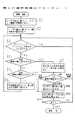
次に、図6から図10までを参照しながら、図5の情報処理システムにおいて行われる反応領域の第1の選択処理について説明する。
図6は、第1の選択処理のフローチャートである。図6において処理が開始されると、CPU21は、まずユーザの指示に基づいてオプション機能の初期設定を行い、拡大サイズや拡大枠内の表示色等を設定する(ステップS1)。これらの初期設定を行わない場合はデフォルト値が採用される。オプション機能の種類と内容については後述することにする。
【0036】
次に、ユーザの指示に基づいて画面表示の設定を行う(ステップS2)。ユーザは、例えばポインティング・デバイスの操作性を無視して、画面上に表示するデータの外形を必要なだけ小さく表示するように設定することができる。つまり、ポインティング・デバイスの操作性以外の要件で、反応領域の大きさを自由に決定できる。この設定により、1つの画面上に沢山の反応領域を表示することが可能となる。
【0037】
次に、ポインティング・デバイスによりユーザからの要求が入力されたかどうかを判定する(ステップS3)。ここで、要求入力とは、例えばマウスボタンのクリック操作を意味する。入力がなければそのまま待機し、要求を受け取った場合は、次に、画面上に表示している一部またはすべての反応領域が既に拡大しているかどうかを判別する(ステップS4)。
【0038】
反応領域が未拡大と判別した場合、次に、ポインティング・デバイスで選択指示された領域が、指示により反応する反応領域か、または非反応領域かを判別する(ステップS5)。そして、反応領域と判別した場合は、それに対応して登録されている処理を実行をする(ステップS10)。
【0039】
ステップS5において、選択された領域が非反応領域と判別した場合は、CPU21および入出力部24は、画面上に表示している一部またはすべての反応領域を拡大して表示する(ステップS6)。このとき、図2の拡大部分14のような新たに拡大された部分は、例えば半透明の色で表示される。そして、ステップS3以降の処理が繰り返される。
【0040】
また、ステップS4において、反応領域が拡大済と判別した場合は、CPU21および入出力部24は、拡大表示された反応領域の拡大部分を非反応領域にして拡大表示を消去する(ステップS7)。そして、CPU21は、ステップS3で選択指示された領域が、元の反応領域と拡大部分と非反応領域のうちのいずれに該当するかを判別する(ステップS8)。ここでの非反応領域とは、元の反応領域と拡大部分以外の領域を指す。
【0041】
そして、拡大前の元の反応領域と判別した場合は、拡大前に元の反応領域が選択された場合と同じく、対応する処理を実行する(ステップS10)。また、拡大部分と判別した場合は、元の反応領域が選択されたものとみなして(ステップS9)、ステップS10の処理を行う。また、非反応領域と判別した場合は、そのままステップS3以降の処理を繰り返す。
【0042】
ステップS10の処理の後、CPU21は全体の処理を終了するかどうか判断する(ステップS11)。終了しない場合はステップS3以降の処理を繰り返し、ユーザからの終了指示などがあれば処理を終了する。
【0043】
図6の第1の選択処理によれば、ポインティング・デバイスによる指示を受け付ける反応領域が大きい場合、それをあらかじめ小さく表示するように設定することにより、一画面に表示可能な反応領域の数を増やすことができる。また、必要な反応領域を拡大表示することにより、ポインティング・デバイス操作の困難性が回避され、選択指示がし易くなる。
【0044】
また、反応領域が沢山ある場合でも、反応領域を拡大表示することにより、必要とする反応領域が見つけ易くなる。さらに、第1の選択処理のアルゴリズムは従来の選択処理のプログラムの内容に依存せず、それとは独立に組み込むことができる。したがって、非常に汎用性の高いアルゴリズムになっている。
【0045】
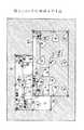
ここで、マルチウィンドウ・システムをサポートするオペレーティング・システムであるWindows(登録商標)の画面を例にとって、具体的な実施形態を説明する。図7は、通常のWindows(登録商標)の表示画面である。図7においては、第1画面、第2画面にそれぞれ対応する2枚のウィンドウW1、W2が重複して表示されており、ウィンドウW2にはアイコンA、Bが表示され、ウィンドウW1にはアイコンC、D、および第2画面のアイコン32が表示されている。
【0046】
また、▲1▼は反応領域を表しており、マウスカーソル31をこれらの領域に合わせてクリック操作を行うと、それぞれに対応して登録された処理が実行される。このように、反応領域は必ずしもアイコンのみを指すものではなく、ウィンドウの枠線、角(頂点)、罫線で囲まれた特定の領域等も反応領域に含まれる。これに対して、斜線領域は、従来ではクリック操作に反応することのなかった非反応領域を表す。
【0047】
ここで、ウィンドウW1の★印の領域をマウスにより指示した場合には、反応領域拡大装置のオプション機能を設定する初期設定画面が表示される。図8は、初期設定画面の一例を示している。図8では、各オプション機能に対応する選択ボタンが表示されており、拡大サイズ設定41を選択すると、反応領域の拡大サイズを指定することができる。
【0048】
また、拡大範囲設定42を選択すると、元の反応領域に対してどの範囲に拡大部分を表示するかを指定できる。例えば、拡大範囲として、元の反応領域の属するウィンドウ内のみ、ウィンドウ外のみ、ウィンドウ内とウィンドウ外の両方のうちいずれかを指定することが考えられる。
【0049】
また、拡大対象設定43を選択すると、表示された反応領域のうちどれを拡大処理の対象とするかを指定できる。例えば、拡大対象として、マウスカーソル31の位置に近い反応領域のみを指定することもでき、マウスカーソル31が存在するウィンドウのすべての反応領域を指定することもできる。さらに、表示されている反応領域のすべてを拡大対象に指定してもよい。
【0050】
また、拡大枠色設定44を選択すると、拡大部分の外周を表す輪郭線の表示色を指定でき、拡大枠内色設定45を選択すると、拡大部分の内部領域の表示色を指定できる。
【0051】
また、画面分割設定46を選択すると、画面分割表示の有無を指定でき、目印表示設定47を選択すると、拡大部分に対する目印付加などのトリミングの有無を指定できる。画面分割およびトリミング表示の具体例については後述する。
【0052】
また、モノクロ対処48を選択すると、色の濃淡により拡大部分を区別して表示したり、拡大部分のみをモノクロ表示にしたりする指定ができる。そのほかにも、元の反応領域と拡大部分の相対的な位置関係など、拡大表示に関する様々な設定を行うことが可能である。
【0053】
これらの各オプション機能には、あらかじめデフォルト値が設定されており、初期設定を行わない場合は、それらのデフォルト値が採用される。また、初期設定画面でキャンセル49を選択すると設定が無効化され、前回の設定値またはデフォルト値が有効となる。逆に、決定50を選択すると設定が有効となり、対応するオプション機能が設定値にしたがって変更される。
【0054】
以下では、図6のステップS2で初期設定を行わずに、デフォルトの設定で選択指示を行った場合について記述する。
図7において、▲1▼で示される反応領域のいずれかがマウスにより指示された場合には、ステップS3の判定がYES、ステップS4の判定がNO、ステップS5の判定がYESとなり、従来通り、指示された反応領域に対応する処理が行われる(ステップS10)。
【0055】
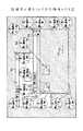
また、図7の斜線領域がマウスにより指示された場合には、ステップS5の判定がNOとなり、図9に示すように、画面上に表示されている全反応領域に扇形の拡大部分が付加され、その付加領域が半透明色で表示される(ステップS6)。
【0056】
図10は、図6のステップS6における反応領域拡大処理の一例を示すフローチャートである。図10において処理が開始されると、CPU21は、まず拡大前の表示画面と反応領域をメモリ22に格納する(ステップS12)。
【0057】
次に、各反応領域の外周上のいくつかの基準点から、マウスによりポインティングされたポイント(マウスカーソル31の位置)までの距離を比較して、その長さが一番短くなる基準点を拡大開始ポイントとし、メモリ22に格納する(ステップS13)。
【0058】
一番短くなるパターンが複数パターン存在した場合には、それらのうちで最初に確認した基準点を優先させる。例えば、矩形状のアイコンの場合は、四隅の頂点を基準点として用いることができる。
【0059】
次に、格納された各反応領域の拡大開始ポイントのうち、マウスカーソル31の位置に一番近いものから順に取り出し(ステップS14)、ステップS15〜S17の処理を行う。一番近いポイントが複数存在した場合には、それらのうちで最初に確認したポイントを優先させる。
【0060】
ステップS15では、拡大開始ポイントを中心とし所定の長さを半径とする仮想的な円を作成し、拡大開始ポイントからマウスカーソル31の方向に向かって広がる扇形をその円から切り取って、これを拡大部分とする。そして、拡大部分の領域を表す座標情報を、元の反応領域の識別情報と対応させてメモリ22に格納する。
【0061】
扇形の半径と中心角は、例えば2cmと30度にあらかじめ設定されているが、これらのパラメータを任意に設定するオプション機能を初期設定画面に追加しておいてもよい。
【0062】
ここで、既に拡大した領域と、これから拡大しようとしている領域が重なる場合は、前者の領域の重複部分を無効領域にしてから後者の拡大処理を行う。つまり、前者の拡大部分の上に後者の拡大部分が上書きされることになる。もちろん、前者と後者の関係を逆にしてもよい。
【0063】
ステップS16では、扇形の拡大部分の枠を線画で表示する。ここで、既に拡大した領域と、これから拡大しようとしている領域が重なる場合は、前者の重複部分を非表示にしてから、後者の線画を表示する。
【0064】
ステップS17では、扇形の拡大部分内の半透明の色で表示する。例えば表示色の階調が10段階の場合、拡大部分内のRGBそれぞれの階調パラメータを+2に設定することで、半透明の表示が得られる。
【0065】
次に、未拡大の反応領域が残っているかどうかを調べ(ステップS18)、残っていればステップS14〜S17の処理を繰り返す。そして、反応領域の拡大がすべて完了すると処理を終了する。こうして、図9のような扇形の拡大部分▲2▼が付加的に表示される。
【0066】
尚、ステップS17においては、拡大部分を透明色、不透明色等の他の任意の表示色で表示してもよい。透明色を用いた場合は、拡大部分の枠のみが線画で表示され、枠内は下地(背景)と同じ色になる。
【0067】
図9において、▲1▼で示される元の反応領域のいずれかがマウスにより指示された場合には、図6のステップS3の判定がYES、ステップS4の判定がYESとなり、画面上に拡大表示されている反応領域のうち、▲2▼で示される拡大部分が非反応領域になり、扇形の拡大表示がなくなる(ステップS7)。
【0068】
ここでは、図10のステップS12で記憶された情報に基づいて、拡大前の画面表示と反応領域が復元され、拡大表示が消去される。そして、ステップS8では反応領域に該当するので、従来通り、指示された反応領域に対応する処理が行われる(ステップS10)。
【0069】
図9において、▲2▼で示される拡大部分のいずれかがマウスにより指示された場合にも、▲1▼の領域が指示された場合と同様にして、拡大表示が消去される(ステップS7)。ただし、ステップS8では拡大部分に該当するので、それを拡大元の反応領域と解釈する処理が行われ(ステップS9)、その後に、元の反応領域に対応する処理が行われる(ステップS10)。
【0070】
拡大部分の座標情報はメモリ22内で元の反応領域に関係付けられているので、CPU21はこれを参照することにより、対応する反応領域を特定することができる。
【0071】
例えば、図9の拡大部分33がマウスにより指示された場合には、すべての拡大表示が消去されて、対応するアイコンBが選択された場合と同様の処理が行われる。
【0072】
また、図9において斜線領域がマウスにより指示された場合には、ステップS3の判定がYES、ステップS4の判定がYESとなり、▲2▼で示される拡大部分が非反応領域になって扇形の拡大表示がなくなる(ステップS7)。この場合は、ステップS8において非反応領域に該当するので、図7の状態に戻って次の入力待ちとなる。
【0073】
次に、図11から図15までを参照しながら、図5の情報処理システムにおいて行われる反応領域の第2の選択処理について説明する。
図11は、第2の選択処理のフローチャートである。第2の選択処理において、ステップS21、S22、S23、S24、S25、S28、S29、S30、S31の処理については、図6の第1の選択処理の対応する各ステップと同様であるので、説明を省略する。ここでは、第1の選択処理と異なるステップS26およびS27の処理について説明する。
【0074】
ステップS25において、選択された領域が非反応領域と判別した場合は、CPU21および入出力部24は、画面上に表示している一部またはすべての反応領域を拡大し、拡大部分に処理名を加えて表示する(ステップS26)。
【0075】
処理名は、反応領域に対応して登録されている処理を識別するための識別情報であり、例えば、元の反応領域に表示されていた内容の一部または全部が、この処理名として用いられる。あるいはまた、元の反応領域の特徴を表す他の情報を処理名として用いてもよい。その後、CPU21はステップS23以降の処理を繰り返す。
【0076】
また、ステップS24において、反応領域が拡大済と判別した場合は、CPU21および入出力部24は、拡大表示された反応領域の拡大部分を非反応領域にして拡大表示とその処理名を消去する(ステップS27)。そして、ステップS28以降の処理を行う。
【0077】
第2の選択処理によれば、反応領域の表示内容が分からない、もしくは分かりにくい場合でも、その領域の内容の一部または全部を拡大表示することができ、起動される処理の内容が分かり易くなる。
【0078】
例えば図7において、ウィンドウW1の★印の領域をマウスにより指示した場合には、図8のような初期設定画面が表示され、前述のような様々な初期設定を行うことができる。
【0079】
以下では、図11のステップS22で初期設定を行わずに、デフォルトの設定で選択指示を行った場合について記述する。
図7において、▲1▼で示される反応領域のいずれかがマウスにより指示された場合には、ステップS23の判定がYES、ステップS24の判定がNO、ステップS25の判定がYESとなり、従来通り、指示された反応領域に対応する処理が行われる(ステップS30)。
【0080】
また、図7の斜線領域がマウスにより指示された場合には、ステップS25の判定がNOとなり、図12に示すように、マウスカーソルが存在しているウィンドウW2内の全反応領域に円形の線画枠で囲まれた拡大部分が付加され、元の反応領域と関連付けて表示される。そして、拡大部分の枠内には、元の反応領域に対応する処理名が表示される(ステップS26)。
【0081】
図13は、図11のステップS26における反応領域拡大処理の一例を示すフローチャートである。図13において処理が開始されると、CPU21は、まず拡大前の表示画面と反応領域をメモリ22に格納する(ステップS41)。
【0082】
次に、クリック操作時にマウスカーソル31が属するウィンドウ内の各反応領域について、その外周上のいくつかの基準点からウィンドウ枠までの距離を比較する。そして、図14に示すように、その長さが一番短くなる基準点を拡大元ポイントとし、対応するウィンドウ枠上の点を拡大枠ポイントとして、メモリ22に格納する(ステップS42)。
【0083】
一番短くなるパターンが複数パターン存在した場合には、それらのうちで最初に確認した基準点を優先させる。例えば、矩形状のアイコンの場合は、四隅の頂点を基準点として用いることができる。
【0084】
次に、格納された各反応領域の拡大元ポイントのうち、マウスカーソル31の位置に一番近いものから順に取り出し(ステップS43)、ステップS44〜S46の処理を行う。一番近いポイントが複数存在した場合には、それらのうちで最初に確認したポイントを優先させる。
【0085】
ステップS44では、図15に示すように、拡大元ポイントから拡大枠ポイントに向かって、両ポイント間の距離の2倍の長さの線をウィンドウ外の領域まで引く。そして、その線の終端を拡大先ポイントとしてメモリ22に格納する。
【0086】
ステップS45では、拡大先ポイントを中心にして所定の半径の円を線画で表示し、その線画枠内を白色で塗り潰して、これを拡大部分とする。このとき、既に表示した円と重ならないように、必要に応じて円の表示位置を調整する。この吹き出し用の円の半径は、例えば1.5cmにあらかじめ設定されているが、これを任意に設定するオプション機能を初期設定画面に追加しておいてもよい。
【0087】
ステップS46では、元の反応領域に対応する処理名を、拡大先ポイントを中心とする円内に表示する。
ステップS47では、その円内の領域と元の反応領域との関連付けを行い、反応領域を円部分に拡張する。これにより、円形の拡大部分もマウスクリックに反応するようになる。
【0088】
次に、吹き出し用の円の表示可能な領域が残っているかどうかを調べ(ステップS48)、残っていれば次の拡大元ポイントについてステップS43以降の処理を繰り返す。そして、表示可能な領域がなくなったら、その時点で拡大処理を完了する。こうして、図12のような円形の拡大部分▲2▼が付加的に表示される。
【0089】
図12において、▲1▼で示される元の反応領域のいずれかがマウスにより指示された場合には、ステップS23の判定がYES、ステップS24の判定がYESとなり、画面上に拡大表示されている反応領域のうち、▲2▼で示される拡大部分が非反応領域になり、円形の拡大表示がなくなる(ステップS27)。
【0090】
ここでは、図13のステップS41で記憶された情報に基づいて、拡大前の画面表示と反応領域が復元され、拡大表示が消去される。そして、ステップS28では反応領域に該当するので、従来通り、指示された反応領域に対応する処理が行われる(ステップS30)。
【0091】
図12において、▲2▼で示される拡大部分のいずれかがマウスにより指示された場合にも、▲1▼の領域が指示された場合と同様にして、拡大表示が消去される(ステップS27)。ただし、ステップS28では拡大部分に該当するので、それを拡大元の反応領域と解釈する処理が行われ(ステップS29)、その後に、元の反応領域に対応する処理が行われる(ステップS30)。
【0092】
例えば、図12の拡大部分34がマウスにより指示された場合には、すべての拡大表示が消去されて、対応するアイコンBが選択された場合と同様の処理が行われる。
【0093】
また、図12において斜線領域がマウスにより指示された場合には、ステップS23の判定がYES、ステップS24の判定がYESとなり、▲2▼で示される拡大部分が非反応領域になって円形の拡大表示がなくなる(ステップS27)。この場合は、ステップS28において非反応領域に該当するので、図7の状態に戻って次の入力待ちとなる。
【0094】
次に、画面分割およびトリミング表示のオプション機能について説明する。
図8の初期設定画面で、画面分割設定46により画面分割機能が設定されると、CPU21は、拡大処理の際に表示画面の一部を非反応領域にし、それを拡大部分を表示する領域として使用する。
【0095】
例えば、図6のステップS6または図11のステップS26において、CPU21は表示画面を一定の割合で縦方向または横方向に分割する。そして、生成された分割画面のうちマウスカーソル31の位置から一番遠い領域を選び、その分割画面を非反応領域にする。こうして得られた非反応領域内に拡大部分が表示される。
【0096】
このとき、拡大対象となる反応領域の数または拡大部分の面積を計算し、その計算値が一定の基準値を越えるかどうかを調べる。そして、その基準値を越えない範囲内で反応領域を拡大するようにする。この基準値は、拡大部分表示用の分割画面の面積から決めることができる。
【0097】
また、図6のステップS7または図11のステップS27において、CPU21は拡大表示を消去するとともに画面分割を解除し、拡大部分表示用に使用している分割画面を消去する。
【0098】
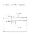
図16は、図7の画面を分割した例を示している。図16においては、画面が上下2つの画面に分割され、上の分割画面内にはウィンドウW2のいくつかの反応領域に対応する拡大部分が処理名とともに表示されている。
【0099】
また、図8の初期設定画面で、目印表示設定47により目印表示機能が設定されると、CPU21は、拡大処理の際に画面上に表示されている一部またはすべての反応領域に目印を付加して表示する。
【0100】
例えば、図6のステップS6または図11のステップS26において、CPU21は拡大部分に目印を付加して表示し、ステップS7またはステップS27において、拡大表示とともに目印表示を消去する。目印の形、色、表示位置等については、ユーザが任意に設定することができる。
【0101】
図17は、図12の拡大部分に目印を付加した例を示している。図17においては、ウィンドウW2の各反応領域に対応する拡大部分にハート型の目印が表示されている。このように、拡大された反応領域に目印を付加することにより、指示すべき領域の存在場所を一目で確認することができる。
【0102】
また、目印を表示するオプションを設定した場合は、それだけでも反応領域が見つけやすくなるので、必ずしも拡大表示を行う必要はない。そこで、拡大表示の代わりに目印表示を行う構成を採ることも可能である。
【0103】
この場合、図6のステップS4または図11のステップS24において、CPU21は、画面上の反応領域に既に目印がついているかどうかを判別し、ステップS6またはステップS26において、反応領域を拡大する代わりに目印を表示する。そして、ステップS7またはステップS27において、目印表示を消去する。
【0104】
以上の実施形態において、反応領域の拡大部分の形状が扇形または円形の場合について説明したが、これらは一例に過ぎず、他の任意の形状の拡大部分を用いて拡大表示を行うことができる。また、拡大部分の表示色についても半透明や白色に限られることはなく、他の任意の色を用いることができる。
【0105】
また、拡大部分は、図2、3、4に示すように元の反応領域を取り囲むように生成してもよく、図9、12に示すように元の反応領域に対して一定の方向に吹き出す形で生成してもよい。
【0106】
さらに、第1および第2の選択処理では、拡大された反応領域が選択されると同時に拡大表示が消去されるが、あらかじめ決められた他の操作が行われたときに拡大表示が消去される構成を採ってもよい。
【0107】
【発明の効果】
本発明によれば、画面に表示された選択肢の中から必要なものを選択し、選択された選択肢に対応する処理を行うシステム全般に対して、次のような効果がある。
【0108】
ポインティング・デバイス等の入力機器により指示を行う領域の拡大表示が可能になり、指示操作がし易くなる。
また、拡大表示することにより、何処にどんな領域があるのか分かり易くなり、多くのアイコン等の中から目的とする反応領域を見つけ出すことが容易になる。
【0109】
さらに、拡大表示機能を備えるシステムの場合、あらかじめ反応領域を小さく表示してもよいので、一画面上に表示できるデータ量を増やすことも可能になる。
【図面の簡単な説明】
【図1】本発明の原理図である。
【図2】第1の拡大例を示す図である。
【図3】第2の拡大例を示す図である。
【図4】第3の拡大例を示す図である。
【図5】実施形態のシステム構成図である。
【図6】第1の選択処理のフローチャートである。
【図7】ウィンドウ内のアイコンを示す図である。
【図8】初期設定画面を示す図である。
【図9】拡大された反応領域を示す図である。
【図10】第1の反応領域拡大処理のフローチャートである。
【図11】第2の選択処理のフローチャートである。
【図12】処理名が表示された反応領域を示す図である。
【図13】第2の反応領域拡大処理のフローチャートである。
【図14】拡大元ポイントと拡大枠ポイントを示す図である。
【図15】拡大先ポイントと拡大部分を示す図である。
【図16】画面分割を示す図である。
【図17】目印表示を示す図である。
【符号の説明】
1 入力手段
2 判別手段
3 拡大手段
4 消去手段
5 表示手段
6、11 表示画面
7、12、15 反応領域
8、13 カーソル
9 拡大された反応領域
21 CPU
22 メモリ
23 バス
24 入出力部
25 キーボード
26 マウス
27 ライトペン
28 タッチパネル
29 ディスプレイ
31 マウスカーソル
32 第2画面のアイコン
33、34 拡大部分
41、42、43、44、45、46、47、48、49、50 選択ボタン
W1、W2 ウィンドウ[0001]
BACKGROUND OF THE INVENTION
The present invention relates to an information processing system that uses a screen display device and an input device such as a pointing device, and determines a choice selected by the input device on the screen and automatically starts a corresponding process. Relates to the device.
[0002]
[Prior art]
In today's information processing system, an input mode is often used in which a required item is selected by operating a pointing device from a plurality of options displayed on the screen of a display device, and processing is instructed. . The pointing device is an input device that can freely specify an arbitrary position on the display screen, and is, for example, a mouse, a trackball, a light pen, a touch panel, or the like.
[0003]
When a large number of icons corresponding to individual processes are displayed on the display screen, the user selects one icon with the pointing device, and the information processing system performs the selected process in response to the instruction. In this way, the user can select a desired process by a simple pointing operation and activate it.
[0004]
In addition, as information processing apparatuses become smaller, various information processing terminals such as PDA (Personal Digial Assistant: new personal information terminal) have been put into practical use. The PDA is a small portable information terminal having a microcomputer, a display, a pen input function, and a communication function.
[0005]
[Problems to be solved by the invention]
However, the conventional information processing system as described above has the following problems.
[0006]
When the icon that is a reaction area that receives an instruction from the pointing device is large, the number of icons that can be displayed on one screen is reduced. For this reason, the user must switch the screen many times in order to find the target icon. In order to avoid this, it is possible to set the icon to be displayed in a small size, but in this case, it becomes difficult to operate the pointing device, and an accurate selection operation cannot be performed as expected.
[0007]
If icons are displayed in a small size, many icons can be displayed at one time, but it is difficult to find a necessary icon from among them. Furthermore, if the icon is small, the display content in the area cannot be read, and it may not be clear which of the graphics displayed on the screen is the icon.
[0008]
In a portable terminal such as a PDA, since the size of the screen itself is limited, such a problem appears more remarkably.
In an information processing system using a screen display device and an input device, the present invention relates to a reaction region enlarging device capable of enlarging and displaying the reaction region on the screen and enhancing the operability of the selection operation by the input device It aims to provide a method.
[0009]
[Means for Solving the Problems]
FIG. 1 is a principle view of a reaction area expanding apparatus according to the present invention. The reaction area enlarging apparatus in FIG. 1 includes an
[0010]
The
The discriminating means 2 discriminates whether the pointing area to which the pointing position belongs is a reaction area that reacts according to an instruction on the screen or a non-reaction area.
[0011]
The enlargement means 3 enlarges an arbitrary reaction area when the indicated area corresponds to the non-reaction area.
The display means 5 displays an enlarged portion of the arbitrary reaction region on the screen in association with the arbitrary reaction region.
[0012]
The reaction area enlarging apparatus in FIG. 1 is used in an information processing apparatus that displays a plurality of process options on a screen and automatically executes the selected process. The
[0013]
The input means 1 transmits position information such as coordinate values representing the indicated position to the determination means 2, and the determination means 2 determines whether the indicated area including the given indicated position is a reaction area or a non-reaction area.
[0014]
The reaction area means an area such as an icon where a corresponding process is started in response to an instruction operation for selecting the area, and a non-reaction area is outside of all reaction areas. In other words, it means a background area that is not related to any reaction area. The reaction area corresponds to one of the above options. When a mouse click operation or the like is performed in the reaction area, the corresponding process is automatically started.
[0015]
When the discriminating means 2 judges that the indicated area corresponds to the non-reactive area, the enlarging means 3 enlarges a part or all of the reaction area on the screen, and the display means 5 displays the enlarged reaction area on the screen. To do. At this time, the enlarged portion newly added to the reaction area before enlargement is displayed in association with the original reaction area.
[0016]
When a selection instruction is given to the enlarged reaction area, it is interpreted in the same way as a selection instruction for the reaction area before enlargement, and the corresponding process is automatically started.
For example, as shown in the upper
[0017]
Therefore, the enlargement means 3 enlarges the reaction area 7, and the display means 5 displays the enlarged reaction area 9 as shown in the lower
[0018]
As described above, by magnifying and displaying the reaction area, the operability of the pointing device or the like is improved, and the user can easily select a specific option.
[0019]
The
[0020]
As shown in the upper
[0021]
Therefore, the process corresponding to the reaction area 7 is automatically started, and the erasing
[0022]
By providing the erasing
[0023]
For example, the
[0024]
DETAILED DESCRIPTION OF THE INVENTION
Hereinafter, embodiments of the present invention will be described in detail with reference to the drawings.
Consider a case in which a reaction area such as a displayed icon or other graphic is selected using a mouse in an information processing system including the reaction area enlarging apparatus of the present invention. For example, as shown in FIG. 2, when the user performs a mouse button click operation when the
[0025]
Thereby, when the
[0026]
Next, when the user moves the
[0027]
When two or more reaction areas are displayed in the
[0028]
In the example shown in FIG. 3, only the
[0029]
Furthermore, the number of reaction regions to be expanded can be determined in advance. In this case, during the enlargement process, the reaction area enlarging apparatus counts the number of target reaction areas, and checks whether the count exceeds a predetermined value. Then, the reaction region is expanded within a range not exceeding the certain value. As a result, the number of enlarged reaction areas displayed in the screen can be limited.
[0030]
FIG. 5 is a configuration diagram of the information processing system according to the embodiment. The system of FIG. 5 includes a
[0031]
When a reaction area such as an icon is displayed on the screen of the
[0032]
The
[0033]
In response to this, the input /
[0034]
The selection operation of the reaction area is not limited to a pointing device such as a mouse, but can be performed by an arbitrary input method such as a keyboard and cursor. However, in the following embodiment, a case where a selection operation is performed by a pointing device is considered.
[0035]
Next, the first reaction region selection process performed in the information processing system of FIG. 5 will be described with reference to FIGS.
FIG. 6 is a flowchart of the first selection process. When the process is started in FIG. 6, the
[0036]
Next, the screen display is set based on the user instruction (step S2). For example, the user can set the outer shape of data displayed on the screen to be displayed as small as necessary while ignoring the operability of the pointing device. That is, the size of the reaction region can be freely determined by requirements other than the operability of the pointing device. With this setting, it is possible to display a large number of reaction areas on one screen.
[0037]
Next, it is determined whether or not a request from the user is input by the pointing device (step S3). Here, the request input means, for example, a mouse button click operation. If there is no input, the process waits as it is. If a request is received, it is next determined whether or not some or all of the reaction areas displayed on the screen have already been enlarged (step S4).
[0038]
If it is determined that the reaction area has not been enlarged, it is then determined whether the area selected and instructed by the pointing device is a reaction area that reacts according to the instruction or a non-reaction area (step S5). If it is determined that the region is a reaction region, the corresponding registered process is executed (step S10).
[0039]
If it is determined in step S5 that the selected region is a non-reaction region, the
[0040]
If it is determined in step S4 that the reaction region has been enlarged, the
[0041]
If it is determined that the original reaction region is not enlarged, the corresponding process is executed as in the case where the original reaction region is selected before enlargement (step S10). If it is determined that the region is an enlarged portion, it is assumed that the original reaction region has been selected (step S9), and the process of step S10 is performed. If it is determined that the region is a non-reactive region, the processing from step S3 is repeated as it is.
[0042]
After the process of step S10, the
[0043]
According to the first selection process of FIG. 6, when the reaction area that receives an instruction from the pointing device is large, the number of reaction areas that can be displayed on one screen is increased by setting the reaction area to be displayed in a small size in advance. be able to. Further, by enlarging and displaying a necessary reaction area, difficulty of pointing and device operation is avoided, and it becomes easy to make a selection instruction.
[0044]
Even if there are many reaction areas, the necessary reaction areas can be easily found by enlarging the reaction areas. Further, the algorithm of the first selection process does not depend on the contents of the conventional selection process program, and can be incorporated independently of the contents. Therefore, the algorithm is very versatile.
[0045]
Here, a specific embodiment will be described with reference to an example of a Windows (registered trademark) screen that is an operating system that supports a multi-window system. FIG. 7 is a normal Windows (registered trademark) display screen. In FIG. 7, two windows W1 and W2 respectively corresponding to the first screen and the second screen are displayed in an overlapping manner.2 Displays icons A and B, and
[0046]
In addition, (1) represents a reaction area. When the
[0047]
Here, when an area marked with a star is indicated with the mouse, an initial setting screen for setting an optional function of the reaction area enlarging apparatus is displayed. FIG. 8 shows an example of the initial setting screen. In FIG. 8, a selection button corresponding to each optional function is displayed, and when the enlargement size setting 41 is selected, the enlargement size of the reaction area can be designated.
[0048]
When the enlargement range setting 42 is selected, it is possible to designate in which range the enlargement portion is displayed with respect to the original reaction area. For example, as the enlargement range, it is conceivable that only the inside of the window to which the original reaction area belongs, only the outside of the window, or both the inside and outside of the window is designated.
[0049]
Further, when the enlargement target setting 43 is selected, it is possible to designate which of the displayed reaction areas is to be enlarged. For example, only the reaction area close to the position of the
[0050]
When the enlargement frame color setting 44 is selected, the display color of the outline representing the outer periphery of the enlarged portion can be designated, and when the enlargement frame inner color setting 45 is selected, the display color of the internal region of the enlarged portion can be designated.
[0051]
When the screen division setting 46 is selected, the presence / absence of screen division display can be designated. When the mark display setting 47 is selected, the presence / absence of trimming such as addition of a mark to the enlarged portion can be designated. Specific examples of screen division and trimming display will be described later.
[0052]
When the monochrome handling 48 is selected, it is possible to specify that the enlarged portion is displayed by distinguishing the shades of colors, or that only the enlarged portion is displayed in monochrome. In addition, various settings relating to the enlarged display such as the relative positional relationship between the original reaction area and the enlarged portion can be performed.
[0053]
Default values are set in advance for each of these optional functions, and these default values are adopted when initial setting is not performed. If cancel 49 is selected on the initial setting screen, the setting is invalidated and the previous set value or default value becomes valid. On the contrary, when the decision 50 is selected, the setting becomes valid, and the corresponding optional function is changed according to the setting value.
[0054]
In the following, a case will be described in which the initial setting is not performed in step S2 of FIG.
In FIG. 7, when any of the reaction areas indicated by (1) is instructed by the mouse, the determination in step S3 is YES, the determination in step S4 is NO, and the determination in step S5 is YES. Processing corresponding to the instructed reaction region is performed (step S10).
[0055]
If the hatched area in FIG. 7 is instructed by the mouse, the determination in step S5 is NO, and a fan-shaped enlarged portion is added to all the reaction areas displayed on the screen as shown in FIG. The additional area is displayed in a translucent color (step S6).
[0056]
FIG. 10 is a flowchart showing an example of the reaction region expansion process in step S6 of FIG. When the process is started in FIG. 10, the
[0057]
Next, the distance from several reference points on the outer periphery of each reaction area to the point pointed by the mouse (the position of the mouse cursor 31) is compared, and the reference point with the shortest length is expanded. The starting point is stored in the memory 22 (step S13).
[0058]
If there are a plurality of patterns that are the shortest, the first confirmed reference point is given priority. For example, in the case of a rectangular icon, vertices at four corners can be used as reference points.
[0059]
Next, out of the stored enlargement start points of each reaction region, the one closest to the position of the
[0060]
In step S15, a virtual circle centered on the enlargement start point and having a predetermined length as a radius is created, and a fan shape extending from the enlargement start point in the direction of the
[0061]
The fan-shaped radius and center angle are set in advance to, for example, 2 cm and 30 degrees, but an optional function for arbitrarily setting these parameters may be added to the initial setting screen.
[0062]
Here, if the already enlarged area and the area to be enlarged overlap, the overlapping process of the former area is made an invalid area and the latter enlargement process is performed. That is, the latter enlarged portion is overwritten on the former enlarged portion. Of course, the relationship between the former and the latter may be reversed.
[0063]
In step S16, the frame of the fan-shaped enlarged portion is displayed as a line drawing. Here, when the already enlarged area and the area to be enlarged overlap, the former overlapping portion is hidden and then the latter line drawing is displayed.
[0064]
In step S17, the image is displayed in a translucent color within the fan-shaped enlarged portion. For example, when the gradation of the display color is 10 levels, a translucent display can be obtained by setting the gradation parameters of RGB in the enlarged portion to +2.
[0065]
Next, it is checked whether or not an unexpanded reaction region remains (step S18), and if it remains, the processes of steps S14 to S17 are repeated. Then, when all the expansion of the reaction area is completed, the process is terminated. Thus, a fan-shaped enlarged portion (2) as shown in FIG. 9 is additionally displayed.
[0066]
In step S17, the enlarged portion may be displayed in another arbitrary display color such as a transparent color or an opaque color. When a transparent color is used, only the frame of the enlarged portion is displayed as a line drawing, and the inside of the frame is the same color as the background (background).
[0067]
In FIG. 9, when any one of the original reaction areas indicated by (1) is instructed by the mouse, the determination in step S3 in FIG. 6 is YES and the determination in step S4 is YES, and the enlarged display is displayed on the screen. Among the reaction areas that have been set, the enlarged portion indicated by (2) becomes a non-reaction area, and the fan-shaped enlarged display disappears (step S7).
[0068]
Here, based on the information stored in step S12 of FIG. 10, the screen display and the reaction area before enlargement are restored, and the enlarged display is erased. And in step S8, since it corresponds to a reaction area | region, the process corresponding to the instruct | indicated reaction area | region is performed as usual (step S10).
[0069]
In FIG. 9, even when any one of the enlarged portions indicated by (2) is designated by the mouse, the enlarged display is erased in the same manner as when the region of (1) is designated (step S7). . However, since it corresponds to the enlarged portion in step S8, a process for interpreting it as an enlargement source reaction area is performed (step S9), and then a process corresponding to the original reaction area is performed (step S10).
[0070]
Since the coordinate information of the enlarged portion is related to the original reaction area in the
[0071]
For example, when the
[0072]
In addition, in FIG. 9, when the hatched area is instructed by the mouse, the determination in step S3 is YES, the determination in step S4 is YES, and the enlarged portion indicated by (2) becomes a non-reactive area and becomes a fan-shaped expansion The display disappears (step S7). In this case, since it corresponds to a non-reaction region in step S8, the state returns to the state of FIG. 7 and waits for the next input.
[0073]
Next, a second reaction region selection process performed in the information processing system of FIG. 5 will be described with reference to FIGS.
FIG. 11 is a flowchart of the second selection process. In the second selection process, steps S21, S22, S23, S24, S25, S28, S29, S30, and S31 are the same as the corresponding steps of the first selection process in FIG. Is omitted. Here, the processes of steps S26 and S27 different from the first selection process will be described.
[0074]
If it is determined in step S25 that the selected area is a non-reaction area, the
[0075]
The process name is identification information for identifying the process registered corresponding to the reaction area. For example, a part or all of the content displayed in the original reaction area is used as the process name. . Alternatively, other information representing the characteristics of the original reaction region may be used as the process name. Thereafter, the
[0076]
If it is determined in step S24 that the reaction area has been enlarged, the
[0077]
According to the second selection process, even if the display contents of the reaction area are not known or difficult to understand, a part or all of the contents of the area can be enlarged and displayed, and the contents of the activated process can be easily understood. Become.
[0078]
For example, in FIG. 7, when an area marked with a star in the window W1 is designated with the mouse, an initial setting screen as shown in FIG. 8 is displayed, and various initial settings as described above can be performed.
[0079]
In the following, a case will be described in which the initial setting is not performed in step S22 of FIG.
In FIG. 7, when any of the reaction regions indicated by (1) is instructed by the mouse, the determination in step S23 is YES, the determination in step S24 is NO, and the determination in step S25 is YES. A process corresponding to the instructed reaction region is performed (step S30).
[0080]
If the hatched area in FIG. 7 is instructed by the mouse, the determination in step S25 is NO and, as shown in FIG. 12, a circular line drawing is formed on all reaction areas in the window W2 where the mouse cursor exists. An enlarged portion surrounded by a frame is added and displayed in association with the original reaction area. Then, the processing name corresponding to the original reaction area is displayed in the frame of the enlarged portion (step S26).
[0081]
FIG. 13 is a flowchart showing an example of the reaction region expansion process in step S26 of FIG. When the process is started in FIG. 13, the
[0082]
Next, for each reaction region in the window to which the
[0083]
If there are a plurality of patterns that are the shortest, the first confirmed reference point is given priority. For example, in the case of a rectangular icon, vertices at four corners can be used as reference points.
[0084]
Next, out of the stored enlargement source points of each reaction area, the point closest to the position of the
[0085]
In step S44, as shown in FIG. 15, a line twice as long as the distance between the two points is drawn from the enlargement source point to the enlargement frame point to the area outside the window. Then, the end of the line is stored in the
[0086]
In step S45, a circle with a predetermined radius centered on the enlargement point is displayed as a line drawing, the inside of the line drawing frame is filled with white, and this is set as an enlarged portion. At this time, the display position of the circle is adjusted as necessary so as not to overlap the already displayed circle. The radius of the balloon circle is set to 1.5 cm in advance, for example, but an optional function for arbitrarily setting this may be added to the initial setting screen.
[0087]
In step S46, the process name corresponding to the original reaction area is displayed in a circle centered on the enlargement point.
In step S47, the area in the circle is associated with the original reaction area, and the reaction area is expanded to a circle. As a result, the circular enlarged portion also responds to mouse clicks.
[0088]
Next, it is checked whether or not a displayable area of the balloon circle is left (step S48). If it remains, the processes after step S43 are repeated for the next enlargement source point. When there is no displayable area, the enlargement process is completed at that time. Thus, a circular enlarged portion (2) as shown in FIG. 12 is additionally displayed.
[0089]
In FIG. 12, when any one of the original reaction areas indicated by (1) is instructed by the mouse, the determination in step S23 is YES and the determination in step S24 is YES, which is displayed on the screen in an enlarged manner. In the reaction area, the enlarged portion indicated by (2) becomes the non-reaction area, and the circular enlarged display disappears (step S27).
[0090]
Here, based on the information stored in step S41 of FIG. 13, the screen display and the reaction area before enlargement are restored, and the enlarged display is erased. And since it corresponds to a reaction area | region in step S28, the process corresponding to the instruct | indicated reaction area | region is performed as usual (step S30).
[0091]
In FIG. 12, even when any of the enlarged portions indicated by (2) is designated by the mouse, the enlarged display is erased in the same manner as when the area of (1) is designated (step S27). . However, since it corresponds to the enlarged portion in step S28, a process of interpreting it as an enlargement source reaction area is performed (step S29), and thereafter, a process corresponding to the original reaction area is performed (step S30).
[0092]
For example, when the
[0093]
Also, in FIG. 12, when the hatched area is designated by the mouse, the determination in step S23 is YES, the determination in step S24 is YES, and the enlarged portion indicated by (2) becomes a non-reactive area and becomes a circular enlargement. The display disappears (step S27). In this case, since it corresponds to the non-reaction region in step S28, the state returns to the state of FIG. 7 and waits for the next input.
[0094]
Next, optional functions for screen division and trimming display will be described.
When the screen division function is set by the screen division setting 46 in the initial setting screen of FIG. 8, the
[0095]
For example, in step S6 of FIG. 6 or step S26 of FIG. 11, the
[0096]
At this time, the number of reaction regions to be enlarged or the area of the enlarged portion is calculated, and it is checked whether or not the calculated value exceeds a certain reference value. Then, the reaction region is expanded within a range not exceeding the reference value. This reference value can be determined from the area of the divided screen for displaying the enlarged portion.
[0097]
In step S7 in FIG. 6 or step S27 in FIG. 11, the
[0098]
FIG. 16 shows an example in which the screen of FIG. 7 is divided. In FIG. 16, the screen is divided into two upper and lower screens, and in the upper divided screen, enlarged portions corresponding to several reaction areas of the window W2 are displayed together with process names.
[0099]
In addition, when the mark display function is set by the mark display setting 47 in the initial setting screen of FIG. 8, the
[0100]
For example, in step S6 of FIG. 6 or step S26 of FIG. 11, the
[0101]
FIG. 17 shows an example in which a mark is added to the enlarged portion of FIG. In FIG. 17, a heart-shaped mark is displayed at an enlarged portion corresponding to each reaction region of the window W2. In this way, by adding a mark to the enlarged reaction region, it is possible to confirm at a glance the location of the region to be pointed.
[0102]
In addition, when an option for displaying a mark is set, it is easy to find a reaction area by itself, and it is not always necessary to perform an enlarged display. Therefore, it is possible to adopt a configuration in which a mark is displayed instead of the enlarged display.
[0103]
In this case, in step S4 of FIG. 6 or step S24 of FIG. 11, the
[0104]
In the above embodiment, the case where the shape of the enlarged portion of the reaction region is a fan shape or a circular shape has been described. Further, the display color of the enlarged portion is not limited to translucent or white, and any other color can be used.
[0105]
Further, the enlarged portion may be generated so as to surround the original reaction region as shown in FIGS. 2, 3, and 4, and blown out in a certain direction with respect to the original reaction region as shown in FIGS. 9 and 12. It may be generated in the form.
[0106]
Further, in the first and second selection processes, the enlarged display is deleted at the same time as the enlarged reaction region is selected, but the enlarged display is deleted when another predetermined operation is performed. A configuration may be adopted.
[0107]
【The invention's effect】
According to the present invention, the following effects are obtained for the entire system that selects a necessary option from options displayed on the screen and performs processing corresponding to the selected option.
[0108]
An area to be instructed can be enlarged and displayed by an input device such as a pointing device, and the instruction operation becomes easy.
Further, the enlarged display makes it easy to understand where and what area exists, and it becomes easy to find the target reaction area from many icons.
[0109]
Furthermore, in the case of a system having an enlarged display function, the reaction area may be displayed in a small size in advance, so that the amount of data that can be displayed on one screen can be increased.
[Brief description of the drawings]
FIG. 1 is a principle diagram of the present invention.
FIG. 2 is a diagram illustrating a first enlarged example.
FIG. 3 is a diagram illustrating a second enlarged example.
FIG. 4 is a diagram illustrating a third enlarged example.
FIG. 5 is a system configuration diagram of the embodiment.
FIG. 6 is a flowchart of a first selection process.
FIG. 7 is a diagram showing icons in a window.
FIG. 8 is a diagram showing an initial setting screen.
FIG. 9 shows an enlarged reaction region.
FIG. 10 is a flowchart of a first reaction region expansion process.
FIG. 11 is a flowchart of second selection processing;
FIG. 12 is a diagram showing a reaction area where a process name is displayed.
FIG. 13 is a flowchart of a second reaction region expansion process.
FIG. 14 is a diagram showing an enlargement source point and an enlargement frame point.
FIG. 15 is a diagram showing an enlargement destination point and an enlarged portion.
FIG. 16 is a diagram illustrating screen division.
FIG. 17 is a diagram showing a mark display.
[Explanation of symbols]
1 Input means
2 discrimination means
3 Enlarging means
4 Erasing means
5 display means
6,11 Display screen
7, 12, 15 reaction area
8, 13 Cursor
9 Expanded reaction area
21 CPU
22 memory
23 Bus
24 I / O section
25 keyboard
26 mouse
27 Light pen
28 Touch panel
29 display
31 Mouse cursor
32 Second screen icons
33, 34 Enlarged part
41, 42, 43, 44, 45, 46, 47, 48, 49, 50 Select button
W1, W2 window
Claims (23)
Translated fromJapanese前記画面上でユーザが任意の位置を指定するための位置指定手段と、
前記位置指定手段によって指定される前記画面上の位置でユーザが選択を指示するための操作を行ったときに、該位置を指示位置として認識し、該指示位置に関する位置情報を入力する入力手段と、
前記指示位置の属する指示領域が、前記画面上で指示により反応する反応領域か、または非反応領域かを判別する判別手段と、
前記指示領域が前記非反応領域に対応する時、任意の反応領域を拡大する拡大手段と、
前記任意の反応領域の拡大部分を、該任意の反応領域と関連付けて前記画面上に表示する表示手段と
を備えることを特徴とする反応領域拡大装置。In an information processing apparatus that displays a plurality of processing options on the screen and automatically executes the selected processing,
Position designation means for the user to designate an arbitrary position on the screen;
An input means for recognizing the position as an indicated position and inputting position information relating to the indicated position when the user performs an operation for instructing selection at the position on the screen specified by the position specifying means; ,
A discriminating means for discriminating whether the pointing area to which the pointing position belongs is a reaction area that reacts according to an instruction on the screen or a non-reaction area;
An expansion means for expanding an arbitrary reaction area when the indication area corresponds to the non-reaction area;
And a display means for displaying an enlarged portion of the arbitrary reaction area on the screen in association with the arbitrary reaction area.
前記画面上でユーザが任意の位置を指定するための位置指定手段と、
前記位置指定手段によって指定される前記画面上の位置でユーザが選択を指示するための操作を行ったときに、該位置を指示位置として認識し、該指示位置に関する位置情報を入力する入力手段と、
前記指示位置の属する指示領域が、前記選択肢のうちの1つに対応するかどうかを判別する判別手段と、
前記指示領域がいずれの選択肢にも対応しない時、任意の反応領域を拡大する拡大手段と、
前記任意の反応領域の拡大部分を、該任意の反応領域と関連付けて前記画面上に表示する表示手段と
を備えることを特徴とする反応領域拡大装置。In an information processing apparatus that displays a plurality of processing options on the screen and automatically executes the selected processing,
Position designation means for the user to designate an arbitrary position on the screen;
An input means for recognizing the position as an indicated position and inputting position information relating to the indicated position when the user performs an operation for instructing selection at the position on the screen specified by the position specifying means; ,
A discriminating means for discriminating whether an indication area to which the indication position belongs corresponds to one of the options;
When the indication area does not correspond to any option, an expansion means for expanding an arbitrary reaction area;
And a display means for displaying an enlarged portion of the arbitrary reaction area on the screen in association with the arbitrary reaction area.
前記画面上でユーザが任意の位置を指定するための位置指定手段と、
前記位置指定手段によって指定される前記画面上の位置でユーザが選択を指示するための操作を行ったときに、該位置を指示位置として認識し、該指示位置に関する位置情報を入力する入力手段と、
前記指示位置の属する指示領域が、前記画面上で指示により反応する反応領域か、または非反応領域かを判別する判別手段と、
前記指示領域が前記非反応領域に対応する時、前記画面上で任意の反応領域に目印を付加して表示する表示手段と
を備えることを特徴とする反応領域表示装置。In an information processing apparatus that displays a plurality of processing options on the screen and automatically executes the selected processing,
Position designation means for the user to designate an arbitrary position on the screen;
An input means for recognizing the position as an indicated position and inputting position information relating to the indicated position when the user performs an operation for instructing selection at the position on the screen specified by the position specifying means; ,
A discriminating means for discriminating whether the pointing area to which the pointing position belongs is a reaction area that reacts according to an instruction on the screen or a non-reaction area;
A reaction area display device comprising: display means for displaying a mark on an arbitrary reaction area on the screen when the indication area corresponds to the non-reaction area.
前記画面上でユーザが任意の位置を指定して前記画面上の該位置でユーザが選択を指示するための操作を行ったときに、該位置を指示位置として認識し、該指示位置に関する位置情報を入力し、
前記指示位置の属する指示領域が、前記画面上で指示により反応する反応領域か、または非反応領域かを判別し、
前記指示領域が前記非反応領域に対応する時、任意の反応領域を拡大し、
前記任意の反応領域の拡大部分を、該任意の反応領域と関連付けて前記画面上に表示する
ことを特徴とする反応領域拡大方法。Display multiple processing options on the screen,
When the user designates an arbitrary position on the screen and the user performs an operation for instructing selection at the position on the screen, the position is recognized as the designated position, and position information regarding the designated position Enter
It is determined whether the indication area to which the indication position belongs is a reaction area that reacts according to an instruction on the screen or a non-reaction area,
When the indicating area corresponds to the non-reactive area, an arbitrary reaction area is enlarged,
An enlarged portion of the arbitrary reaction region is displayed on the screen in association with the arbitrary reaction region.
前記画面上でユーザが任意の位置を指定して前記画面上の該位置でユーザが選択を指示するための操作を行ったときに、該位置を指示位置として認識し、該指示位置に関する位置情報を入力し、
前記指示位置の属する指示領域が、前記選択肢のうちの1つに対応するかどうかを判別し、
前記指示領域がいずれの選択肢にも対応しない時、任意の反応領域を拡大し、
前記任意の反応領域の拡大部分を、該任意の反応領域と関連付けて前記画面上に表示する
ことを特徴とする反応領域拡大方法。Display multiple processing options on the screen,
When the user designates an arbitrary position on the screen and the user performs an operation for instructing selection at the position on the screen, the position is recognized as the designated position, and position information regarding the designated position Enter
Determining whether the pointing area to which the pointing position belongs corresponds to one of the options;
When the indication area does not correspond to any option, enlarge any reaction area,
An enlarged portion of the arbitrary reaction region is displayed on the screen in association with the arbitrary reaction region.
Priority Applications (2)
| Application Number | Priority Date | Filing Date | Title |
|---|---|---|---|
| JP06075896AJP3784031B2 (en) | 1996-03-18 | 1996-03-18 | Reaction area expansion apparatus and method for expanding an area that responds to a selection operation on a display screen |
| US08/735,439US5986639A (en) | 1996-03-18 | 1997-01-02 | Apparatus and method for extending a reactive area on a display screen |
Applications Claiming Priority (1)
| Application Number | Priority Date | Filing Date | Title |
|---|---|---|---|
| JP06075896AJP3784031B2 (en) | 1996-03-18 | 1996-03-18 | Reaction area expansion apparatus and method for expanding an area that responds to a selection operation on a display screen |
Publications (2)
| Publication Number | Publication Date |
|---|---|
| JPH09251341A JPH09251341A (en) | 1997-09-22 |
| JP3784031B2true JP3784031B2 (en) | 2006-06-07 |
Family
ID=13151507
Family Applications (1)
| Application Number | Title | Priority Date | Filing Date |
|---|---|---|---|
| JP06075896AExpired - LifetimeJP3784031B2 (en) | 1996-03-18 | 1996-03-18 | Reaction area expansion apparatus and method for expanding an area that responds to a selection operation on a display screen |
Country Status (2)
| Country | Link |
|---|---|
| US (1) | US5986639A (en) |
| JP (1) | JP3784031B2 (en) |
Families Citing this family (42)
| Publication number | Priority date | Publication date | Assignee | Title |
|---|---|---|---|---|
| JP2938420B2 (en)* | 1998-01-30 | 1999-08-23 | インターナショナル・ビジネス・マシーンズ・コーポレイション | Function selection method and apparatus, storage medium storing control program for selecting functions, object operation method and apparatus, storage medium storing control program for operating objects, storage medium storing composite icon |
| US6285374B1 (en)* | 1998-04-06 | 2001-09-04 | Microsoft Corporation | Blunt input device cursor |
| US6211856B1 (en)* | 1998-04-17 | 2001-04-03 | Sung M. Choi | Graphical user interface touch screen with an auto zoom feature |
| US6567070B1 (en)* | 1999-08-10 | 2003-05-20 | Intel Corporation | Selection of objects in a graphical user interface |
| US6559873B1 (en)* | 1999-12-17 | 2003-05-06 | International Business Machines Corporation | Displaying menu choices adjacent to spatially isolating regions enabling different cursor movement speeds and other user notification means |
| US6628315B1 (en)* | 1999-12-17 | 2003-09-30 | International Business Machines Corporation | System, method, and program for providing a barrier around a menu choice to reduce the chance of a user accidentally making a selection error |
| US7434177B1 (en) | 1999-12-20 | 2008-10-07 | Apple Inc. | User interface for providing consolidation and access |
| US6686938B1 (en) | 2000-01-05 | 2004-02-03 | Apple Computer, Inc. | Method and system for providing an embedded application toolbar |
| JPWO2002046899A1 (en)* | 2000-12-08 | 2004-04-08 | 富士通株式会社 | Window display control method, window display control device, and computer-readable recording medium recording program |
| US6947062B2 (en)* | 2001-07-23 | 2005-09-20 | Koninklijke Philips Electronics N.V. | Seamlessly combined freely moving cursor and jumping highlights navigation |
| KR100902740B1 (en)* | 2002-06-27 | 2009-06-15 | 주식회사 케이티 | Automatic click signal input device using mouse movement and its method |
| US7343566B1 (en) | 2002-07-10 | 2008-03-11 | Apple Inc. | Method and apparatus for displaying a window for a user interface |
| US7404149B2 (en)* | 2003-03-28 | 2008-07-22 | International Business Machines Corporation | User-defined assistive GUI glue |
| JP4172307B2 (en)* | 2003-03-31 | 2008-10-29 | 富士ゼロックス株式会社 | 3D instruction input device |
| US20040212601A1 (en)* | 2003-04-24 | 2004-10-28 | Anthony Cake | Method and apparatus for improving accuracy of touch screen input devices |
| US7600201B2 (en)* | 2004-04-07 | 2009-10-06 | Sony Corporation | Methods and apparatuses for viewing choices and making selections |
| EP1763732A2 (en)* | 2004-06-29 | 2007-03-21 | Koninklijke Philips Electronics N.V. | Discontinuous zoom |
| JP4170314B2 (en)* | 2005-05-25 | 2008-10-22 | 株式会社スクウェア・エニックス | Scroll display control device, program, and recording medium |
| US7966573B2 (en)* | 2006-02-17 | 2011-06-21 | Microsoft Corporation | Method and system for improving interaction with a user interface |
| US7843427B2 (en)* | 2006-09-06 | 2010-11-30 | Apple Inc. | Methods for determining a cursor position from a finger contact with a touch screen display |
| US8839142B2 (en) | 2007-06-08 | 2014-09-16 | Apple Inc. | Desktop system object removal |
| CN101743529B (en)* | 2007-07-11 | 2012-06-13 | 株式会社爱可信 | Portable information terminal and its control method |
| US8432365B2 (en)* | 2007-08-30 | 2013-04-30 | Lg Electronics Inc. | Apparatus and method for providing feedback for three-dimensional touchscreen |
| US8219936B2 (en)* | 2007-08-30 | 2012-07-10 | Lg Electronics Inc. | User interface for a mobile device using a user's gesture in the proximity of an electronic device |
| KR101183450B1 (en) | 2007-11-30 | 2012-09-17 | 가부시키가이샤 코나미 데지타루 엔타테인멘토 | Computer readable medium on which game program is recorded, game device and game control method |
| JP4605478B2 (en) | 2007-12-19 | 2011-01-05 | ソニー株式会社 | Information processing apparatus, display control method, and display control program |
| JP5033616B2 (en)* | 2007-12-27 | 2012-09-26 | 京セラ株式会社 | Electronics |
| JP4990753B2 (en)* | 2007-12-28 | 2012-08-01 | パナソニック株式会社 | Electronic device input device, input operation processing method, and input control program |
| TW201020901A (en)* | 2008-11-20 | 2010-06-01 | Ibm | Visual feedback for drag-and-drop operation with gravitational force model |
| JP5581817B2 (en)* | 2010-06-03 | 2014-09-03 | ソニー株式会社 | Control system, control device, handheld device, control method and program. |
| US9542202B2 (en) | 2010-10-19 | 2017-01-10 | Apple Inc. | Displaying and updating workspaces in a user interface |
| US10740117B2 (en) | 2010-10-19 | 2020-08-11 | Apple Inc. | Grouping windows into clusters in one or more workspaces in a user interface |
| US9658732B2 (en) | 2010-10-19 | 2017-05-23 | Apple Inc. | Changing a virtual workspace based on user interaction with an application window in a user interface |
| US9292196B2 (en) | 2010-10-19 | 2016-03-22 | Apple Inc. | Modifying the presentation of clustered application windows in a user interface |
| US10152192B2 (en) | 2011-02-21 | 2018-12-11 | Apple Inc. | Scaling application windows in one or more workspaces in a user interface |
| US20120278754A1 (en)* | 2011-04-29 | 2012-11-01 | Google Inc. | Elastic Over-Scroll |
| KR20130011167A (en)* | 2011-07-20 | 2013-01-30 | 삼성전자주식회사 | Display device and method thereoof |
| US20130042208A1 (en)* | 2011-08-10 | 2013-02-14 | International Business Machines Coporation | Cursor for enhanced interaction with user interface controls |
| JP5246974B2 (en)* | 2012-01-25 | 2013-07-24 | パナソニック株式会社 | Electronic device input device, input operation processing method, and input control program |
| JP2015022675A (en)* | 2013-07-23 | 2015-02-02 | 太郎 諌山 | Electronic device, interface control method, and program |
| JP6359165B2 (en)* | 2017-08-24 | 2018-07-18 | 三菱電機株式会社 | Terminal program |
| JP7490967B2 (en)* | 2020-01-27 | 2024-05-28 | 富士通株式会社 | DISPLAY CONTROL PROGRAM, DISPLAY CONTROL METHOD, AND DISPLAY CONTROL DEVICE |
Family Cites Families (9)
| Publication number | Priority date | Publication date | Assignee | Title |
|---|---|---|---|---|
| US4587520A (en)* | 1983-04-07 | 1986-05-06 | Rca Corporation | Cursor controlled page selection in a video display |
| US4586035A (en)* | 1984-02-29 | 1986-04-29 | International Business Machines Corporation | Display terminal with a cursor responsive virtual distributed menu |
| US4698625A (en)* | 1985-05-30 | 1987-10-06 | International Business Machines Corp. | Graphic highlight adjacent a pointing cursor |
| US5243697A (en)* | 1989-03-15 | 1993-09-07 | Sun Microsystems, Inc. | Method and apparatus for selecting button functions and retaining selected options on a display |
| JPH03292524A (en)* | 1990-04-11 | 1991-12-24 | Oki Electric Ind Co Ltd | Cursor shift system |
| US5508717A (en)* | 1992-07-28 | 1996-04-16 | Sony Corporation | Computer pointing device with dynamic sensitivity |
| US5488685A (en)* | 1993-01-27 | 1996-01-30 | Apple Computer, Inc. | Method and apparatus for providing visual cues in a graphic user interface |
| US5436666A (en)* | 1993-05-21 | 1995-07-25 | Intel Corporation | Limited-domain motion estimation/compensation for video encoding/decoding |
| US5565888A (en)* | 1995-02-17 | 1996-10-15 | International Business Machines Corporation | Method and apparatus for improving visibility and selectability of icons |
- 1996
- 1996-03-18JPJP06075896Apatent/JP3784031B2/ennot_activeExpired - Lifetime
- 1997
- 1997-01-02USUS08/735,439patent/US5986639A/ennot_activeExpired - Lifetime
Also Published As
| Publication number | Publication date |
|---|---|
| US5986639A (en) | 1999-11-16 |
| JPH09251341A (en) | 1997-09-22 |
Similar Documents
| Publication | Publication Date | Title |
|---|---|---|
| JP3784031B2 (en) | Reaction area expansion apparatus and method for expanding an area that responds to a selection operation on a display screen | |
| KR930008269B1 (en) | Display Control Method of Multi Window System | |
| JPH07200237A (en) | Method and system for operation of display of plurality of applications in data processing system | |
| US6476832B1 (en) | Windows display method and apparatus for the left-handed mouse | |
| JPH05265689A (en) | Information processing equipment | |
| US6335740B1 (en) | Data processing apparatus and method for facilitating item selection by displaying guidance images | |
| JP3391852B2 (en) | Document processing apparatus and method | |
| JP2954227B2 (en) | Information processing method | |
| JP3050281B2 (en) | Map information retrieval device | |
| JPH0383121A (en) | Menu display method | |
| JP2705225B2 (en) | CRT display device | |
| JPH09244858A (en) | Window system control method and information processing apparatus | |
| JP3313613B2 (en) | Apparatus and method for automatically correcting window display in multi-window system | |
| JP2679971B2 (en) | Graphic display control device | |
| JPH04163592A (en) | Method of window display | |
| JP3358311B2 (en) | Table processing equipment | |
| JPH08137653A (en) | Window display method, window movement method, and document creation device | |
| JPH11212968A (en) | Document processing apparatus and method | |
| JP2001043391A (en) | Object processing device and storage medium | |
| JPH0497420A (en) | Document processor | |
| JPH0887395A (en) | Icon menu selection method, its system, and information processing apparatus | |
| JP2575636B2 (en) | Graphic display device | |
| JP2730731B2 (en) | Image processing method | |
| JPH1027086A (en) | Display device | |
| JP2002063020A (en) | Map information display method and display device |
Legal Events
| Date | Code | Title | Description |
|---|---|---|---|
| A977 | Report on retrieval | Free format text:JAPANESE INTERMEDIATE CODE: A971007 Effective date:20051018 | |
| A131 | Notification of reasons for refusal | Free format text:JAPANESE INTERMEDIATE CODE: A131 Effective date:20051025 | |
| A521 | Request for written amendment filed | Free format text:JAPANESE INTERMEDIATE CODE: A523 Effective date:20051222 | |
| A131 | Notification of reasons for refusal | Free format text:JAPANESE INTERMEDIATE CODE: A131 Effective date:20060124 | |
| A521 | Request for written amendment filed | Free format text:JAPANESE INTERMEDIATE CODE: A523 Effective date:20060213 | |
| TRDD | Decision of grant or rejection written | ||
| A01 | Written decision to grant a patent or to grant a registration (utility model) | Free format text:JAPANESE INTERMEDIATE CODE: A01 Effective date:20060307 | |
| A61 | First payment of annual fees (during grant procedure) | Free format text:JAPANESE INTERMEDIATE CODE: A61 Effective date:20060313 | |
| R150 | Certificate of patent or registration of utility model | Free format text:JAPANESE INTERMEDIATE CODE: R150 | |
| FPAY | Renewal fee payment (event date is renewal date of database) | Free format text:PAYMENT UNTIL: 20100324 Year of fee payment:4 | |
| FPAY | Renewal fee payment (event date is renewal date of database) | Free format text:PAYMENT UNTIL: 20100324 Year of fee payment:4 | |
| FPAY | Renewal fee payment (event date is renewal date of database) | Free format text:PAYMENT UNTIL: 20110324 Year of fee payment:5 | |
| FPAY | Renewal fee payment (event date is renewal date of database) | Free format text:PAYMENT UNTIL: 20110324 Year of fee payment:5 | |
| FPAY | Renewal fee payment (event date is renewal date of database) | Free format text:PAYMENT UNTIL: 20120324 Year of fee payment:6 | |
| FPAY | Renewal fee payment (event date is renewal date of database) | Free format text:PAYMENT UNTIL: 20130324 Year of fee payment:7 |