JP3783909B2 - CUTTING DEVICE, INFORMATION RECORDING MEDIUM, INFORMATION RECORDING DEVICE, INFORMATION RECORDING METHOD, AND CUTTING METHOD - Google Patents
CUTTING DEVICE, INFORMATION RECORDING MEDIUM, INFORMATION RECORDING DEVICE, INFORMATION RECORDING METHOD, AND CUTTING METHODDownload PDFInfo
- Publication number
- JP3783909B2 JP3783909B2JP14063699AJP14063699AJP3783909B2JP 3783909 B2JP3783909 B2JP 3783909B2JP 14063699 AJP14063699 AJP 14063699AJP 14063699 AJP14063699 AJP 14063699AJP 3783909 B2JP3783909 B2JP 3783909B2
- Authority
- JP
- Japan
- Prior art keywords
- recording
- information
- area
- data
- recorded
- Prior art date
- Legal status (The legal status is an assumption and is not a legal conclusion. Google has not performed a legal analysis and makes no representation as to the accuracy of the status listed.)
- Expired - Fee Related
Links
- 238000000034methodMethods0.000titleclaimsdescription71
- 238000005520cutting processMethods0.000titleclaimsdescription34
- 230000002265preventionEffects0.000claimsdescription27
- 238000004519manufacturing processMethods0.000claimsdescription22
- 238000012790confirmationMethods0.000claimsdescription18
- 238000001514detection methodMethods0.000claimsdescription18
- 230000001678irradiating effectEffects0.000claimsdescription17
- 238000004049embossingMethods0.000claims4
- 238000012545processingMethods0.000description19
- 238000010586diagramMethods0.000description14
- 230000003287optical effectEffects0.000description13
- 238000012937correctionMethods0.000description9
- 230000015572biosynthetic processEffects0.000description4
- 238000000605extractionMethods0.000description4
- 239000011521glassSubstances0.000description3
- 239000000758substrateSubstances0.000description3
- 238000005259measurementMethods0.000description2
- 230000002093peripheral effectEffects0.000description2
- 230000004044responseEffects0.000description2
- 230000000694effectsEffects0.000description1
- 239000000284extractSubstances0.000description1
- 230000010363phase shiftEffects0.000description1
- 238000002360preparation methodMethods0.000description1
- 230000001172regenerating effectEffects0.000description1
- 230000010076replicationEffects0.000description1
- 238000003892spreadingMethods0.000description1
- 230000001360synchronised effectEffects0.000description1
Images


Classifications
- G—PHYSICS
- G11—INFORMATION STORAGE
- G11B—INFORMATION STORAGE BASED ON RELATIVE MOVEMENT BETWEEN RECORD CARRIER AND TRANSDUCER
- G11B7/00—Recording or reproducing by optical means, e.g. recording using a thermal beam of optical radiation by modifying optical properties or the physical structure, reproducing using an optical beam at lower power by sensing optical properties; Record carriers therefor
- G11B7/24—Record carriers characterised by shape, structure or physical properties, or by the selection of the material
- G11B7/26—Apparatus or processes specially adapted for the manufacture of record carriers
- G—PHYSICS
- G11—INFORMATION STORAGE
- G11B—INFORMATION STORAGE BASED ON RELATIVE MOVEMENT BETWEEN RECORD CARRIER AND TRANSDUCER
- G11B7/00—Recording or reproducing by optical means, e.g. recording using a thermal beam of optical radiation by modifying optical properties or the physical structure, reproducing using an optical beam at lower power by sensing optical properties; Record carriers therefor
- G11B7/007—Arrangement of the information on the record carrier, e.g. form of tracks, actual track shape, e.g. wobbled, or cross-section, e.g. v-shaped; Sequential information structures, e.g. sectoring or header formats within a track
- G11B7/00736—Auxiliary data, e.g. lead-in, lead-out, Power Calibration Area [PCA], Burst Cutting Area [BCA], control information
- G—PHYSICS
- G11—INFORMATION STORAGE
- G11B—INFORMATION STORAGE BASED ON RELATIVE MOVEMENT BETWEEN RECORD CARRIER AND TRANSDUCER
- G11B19/00—Driving, starting, stopping record carriers not specifically of filamentary or web form, or of supports therefor; Control thereof; Control of operating function ; Driving both disc and head
- G11B19/02—Control of operating function, e.g. switching from recording to reproducing
- G11B19/04—Arrangements for preventing, inhibiting, or warning against double recording on the same blank or against other recording or reproducing malfunctions
- G—PHYSICS
- G11—INFORMATION STORAGE
- G11B—INFORMATION STORAGE BASED ON RELATIVE MOVEMENT BETWEEN RECORD CARRIER AND TRANSDUCER
- G11B20/00—Signal processing not specific to the method of recording or reproducing; Circuits therefor
- G—PHYSICS
- G11—INFORMATION STORAGE
- G11B—INFORMATION STORAGE BASED ON RELATIVE MOVEMENT BETWEEN RECORD CARRIER AND TRANSDUCER
- G11B20/00—Signal processing not specific to the method of recording or reproducing; Circuits therefor
- G11B20/00086—Circuits for prevention of unauthorised reproduction or copying, e.g. piracy
- G11B20/0021—Circuits for prevention of unauthorised reproduction or copying, e.g. piracy involving encryption or decryption of contents recorded on or reproduced from a record carrier
- G11B20/00217—Circuits for prevention of unauthorised reproduction or copying, e.g. piracy involving encryption or decryption of contents recorded on or reproduced from a record carrier the cryptographic key used for encryption and/or decryption of contents recorded on or reproduced from the record carrier being read from a specific source
- G11B20/00253—Circuits for prevention of unauthorised reproduction or copying, e.g. piracy involving encryption or decryption of contents recorded on or reproduced from a record carrier the cryptographic key used for encryption and/or decryption of contents recorded on or reproduced from the record carrier being read from a specific source wherein the key is stored on the record carrier
- G11B20/00326—Circuits for prevention of unauthorised reproduction or copying, e.g. piracy involving encryption or decryption of contents recorded on or reproduced from a record carrier the cryptographic key used for encryption and/or decryption of contents recorded on or reproduced from the record carrier being read from a specific source wherein the key is stored on the record carrier the key being embossed on the record carrier
- G—PHYSICS
- G11—INFORMATION STORAGE
- G11B—INFORMATION STORAGE BASED ON RELATIVE MOVEMENT BETWEEN RECORD CARRIER AND TRANSDUCER
- G11B20/00—Signal processing not specific to the method of recording or reproducing; Circuits therefor
- G11B20/00086—Circuits for prevention of unauthorised reproduction or copying, e.g. piracy
- G11B20/00572—Circuits for prevention of unauthorised reproduction or copying, e.g. piracy involving measures which change the format of the recording medium
- G11B20/00586—Circuits for prevention of unauthorised reproduction or copying, e.g. piracy involving measures which change the format of the recording medium said format change concerning the physical format of the recording medium
- G—PHYSICS
- G11—INFORMATION STORAGE
- G11B—INFORMATION STORAGE BASED ON RELATIVE MOVEMENT BETWEEN RECORD CARRIER AND TRANSDUCER
- G11B20/00—Signal processing not specific to the method of recording or reproducing; Circuits therefor
- G11B20/00086—Circuits for prevention of unauthorised reproduction or copying, e.g. piracy
- G11B20/0092—Circuits for prevention of unauthorised reproduction or copying, e.g. piracy involving measures which are linked to media defects or read/write errors
- G—PHYSICS
- G11—INFORMATION STORAGE
- G11B—INFORMATION STORAGE BASED ON RELATIVE MOVEMENT BETWEEN RECORD CARRIER AND TRANSDUCER
- G11B20/00—Signal processing not specific to the method of recording or reproducing; Circuits therefor
- G11B20/10—Digital recording or reproducing
- G11B20/12—Formatting, e.g. arrangement of data block or words on the record carriers
- G11B20/1217—Formatting, e.g. arrangement of data block or words on the record carriers on discs
- G—PHYSICS
- G11—INFORMATION STORAGE
- G11B—INFORMATION STORAGE BASED ON RELATIVE MOVEMENT BETWEEN RECORD CARRIER AND TRANSDUCER
- G11B7/00—Recording or reproducing by optical means, e.g. recording using a thermal beam of optical radiation by modifying optical properties or the physical structure, reproducing using an optical beam at lower power by sensing optical properties; Record carriers therefor
- G11B7/007—Arrangement of the information on the record carrier, e.g. form of tracks, actual track shape, e.g. wobbled, or cross-section, e.g. v-shaped; Sequential information structures, e.g. sectoring or header formats within a track
- G—PHYSICS
- G11—INFORMATION STORAGE
- G11B—INFORMATION STORAGE BASED ON RELATIVE MOVEMENT BETWEEN RECORD CARRIER AND TRANSDUCER
- G11B7/00—Recording or reproducing by optical means, e.g. recording using a thermal beam of optical radiation by modifying optical properties or the physical structure, reproducing using an optical beam at lower power by sensing optical properties; Record carriers therefor
- G11B7/12—Heads, e.g. forming of the optical beam spot or modulation of the optical beam
- G11B7/125—Optical beam sources therefor, e.g. laser control circuitry specially adapted for optical storage devices; Modulators, e.g. means for controlling the size or intensity of optical spots or optical traces
- G11B7/126—Circuits, methods or arrangements for laser control or stabilisation
- G—PHYSICS
- G11—INFORMATION STORAGE
- G11B—INFORMATION STORAGE BASED ON RELATIVE MOVEMENT BETWEEN RECORD CARRIER AND TRANSDUCER
- G11B7/00—Recording or reproducing by optical means, e.g. recording using a thermal beam of optical radiation by modifying optical properties or the physical structure, reproducing using an optical beam at lower power by sensing optical properties; Record carriers therefor
- G11B7/24—Record carriers characterised by shape, structure or physical properties, or by the selection of the material
- G11B7/26—Apparatus or processes specially adapted for the manufacture of record carriers
- G11B7/261—Preparing a master, e.g. exposing photoresist, electroforming
- G—PHYSICS
- G11—INFORMATION STORAGE
- G11B—INFORMATION STORAGE BASED ON RELATIVE MOVEMENT BETWEEN RECORD CARRIER AND TRANSDUCER
- G11B20/00—Signal processing not specific to the method of recording or reproducing; Circuits therefor
- G11B20/10—Digital recording or reproducing
- G11B20/18—Error detection or correction; Testing, e.g. of drop-outs
- G11B20/1833—Error detection or correction; Testing, e.g. of drop-outs by adding special lists or symbols to the coded information
- G—PHYSICS
- G11—INFORMATION STORAGE
- G11B—INFORMATION STORAGE BASED ON RELATIVE MOVEMENT BETWEEN RECORD CARRIER AND TRANSDUCER
- G11B20/00—Signal processing not specific to the method of recording or reproducing; Circuits therefor
- G11B20/10—Digital recording or reproducing
- G11B20/12—Formatting, e.g. arrangement of data block or words on the record carriers
- G11B20/1217—Formatting, e.g. arrangement of data block or words on the record carriers on discs
- G11B2020/1259—Formatting, e.g. arrangement of data block or words on the record carriers on discs with ROM/RAM areas
- G—PHYSICS
- G11—INFORMATION STORAGE
- G11B—INFORMATION STORAGE BASED ON RELATIVE MOVEMENT BETWEEN RECORD CARRIER AND TRANSDUCER
- G11B20/00—Signal processing not specific to the method of recording or reproducing; Circuits therefor
- G11B20/10—Digital recording or reproducing
- G11B20/12—Formatting, e.g. arrangement of data block or words on the record carriers
- G11B2020/1264—Formatting, e.g. arrangement of data block or words on the record carriers wherein the formatting concerns a specific kind of data
- G11B2020/1265—Control data, system data or management information, i.e. data used to access or process user data
- G11B2020/1285—Status of the record carrier, e.g. space bit maps, flags indicating a formatting status or a write permission
- G—PHYSICS
- G11—INFORMATION STORAGE
- G11B—INFORMATION STORAGE BASED ON RELATIVE MOVEMENT BETWEEN RECORD CARRIER AND TRANSDUCER
- G11B7/00—Recording or reproducing by optical means, e.g. recording using a thermal beam of optical radiation by modifying optical properties or the physical structure, reproducing using an optical beam at lower power by sensing optical properties; Record carriers therefor
- G11B7/004—Recording, reproducing or erasing methods; Read, write or erase circuits therefor
- G11B7/0045—Recording
- G—PHYSICS
- G11—INFORMATION STORAGE
- G11B—INFORMATION STORAGE BASED ON RELATIVE MOVEMENT BETWEEN RECORD CARRIER AND TRANSDUCER
- G11B7/00—Recording or reproducing by optical means, e.g. recording using a thermal beam of optical radiation by modifying optical properties or the physical structure, reproducing using an optical beam at lower power by sensing optical properties; Record carriers therefor
- G11B7/24—Record carriers characterised by shape, structure or physical properties, or by the selection of the material
- G11B7/2407—Tracks or pits; Shape, structure or physical properties thereof
- G11B7/24073—Tracks
- G11B7/24082—Meandering
- G—PHYSICS
- G11—INFORMATION STORAGE
- G11B—INFORMATION STORAGE BASED ON RELATIVE MOVEMENT BETWEEN RECORD CARRIER AND TRANSDUCER
- G11B7/00—Recording or reproducing by optical means, e.g. recording using a thermal beam of optical radiation by modifying optical properties or the physical structure, reproducing using an optical beam at lower power by sensing optical properties; Record carriers therefor
- G11B7/24—Record carriers characterised by shape, structure or physical properties, or by the selection of the material
- G11B7/26—Apparatus or processes specially adapted for the manufacture of record carriers
- G11B7/263—Preparing and using a stamper, e.g. pressing or injection molding substrates
Landscapes
- Engineering & Computer Science (AREA)
- Signal Processing (AREA)
- Computer Security & Cryptography (AREA)
- Physics & Mathematics (AREA)
- Optics & Photonics (AREA)
- Manufacturing & Machinery (AREA)
- Optical Recording Or Reproduction (AREA)
- Signal Processing For Digital Recording And Reproducing (AREA)
- Management Or Editing Of Information On Record Carriers (AREA)
- Manufacturing Optical Record Carriers (AREA)
Description
Translated fromJapanese【0001】
【発明の属する技術分野】
本発明は、DVD等の情報記録媒体に記録されている記録情報の不正コピーを有効に防止することを可能とする情報記録媒体製造装置、情報記録媒体、情報記録装置及び情報記録方法の技術分野に属する。
【0002】
【従来の技術】
近年、DVDに代表される大容量の光ディスクが、映像や音声などの各種コンテンツを記録するための情報記録媒体として急速に普及しつつある。DVD等の情報記録媒体にディジタルデータとして記録されるこれらのコンテンツは、一般に著作権により保護されるので、他の記録媒体に不正にコピーされることを防止するため、何らかの対策を施す必要がある。
【0003】
このような対策として、情報記録媒体からコンテンツを再生する際に、所定の領域に書き込まれたキーデータを用いてスクランブルを施す方法が知られている。例えば、DVDフォーマットの場合、リードイン領域中のコントロールデータとして、このようなキーデータがコピー禁止情報と共に書き込まれている。そして、記録・再生装置においては、コピーが禁止された情報記録媒体を読み出したとき、コピー禁止情報の判別が行われる。そのため、情報記録媒体のスクランブルは解除されることがなく、情報記録媒体の不正なコピーを防止することができる。
【0004】
【発明が解決しようとする課題】
しかしながら、上述のようにコピーが禁止された情報記録媒体に対し、通常の再生処理によるのではなく、DVD−ROM等からRF信号を読み取って、コピー禁止情報やスクランブルのキーデータの内容にかかわらず、全体的に他の情報記録媒体にハードコピーされる場合がある。最近は、1回のみ記録可能なDVDレコーダブル(DVD−R)や繰り返し記録可能なDVDリライタブル(DVD−RW)が実現しているので、上述のRF信号をDVD−RやDVD−RWに書き込むことにより、元の情報記録媒体と同じデータ内容の光ディスクができることになり、その結果、著作権が侵害されることになる。
【0005】
そこで、本発明は上述した問題に鑑みなされたものであり、情報記録媒体からRF信号を読み取ってハードコピーしようとする場合であっても、情報記録媒体の不正コピーを有効に防止することができる書き込み可能な情報記録媒体、該情報記録媒体を製造する情報記録媒体製造装置、該情報記録媒体への記録を行う情報記録装置及び情報記録方法を提供することを目的とする。
【0006】
【課題を解決するための手段】
上記課題を解決するために、請求項1に記載のカッティング装置は、所定のフォーマットにより記録情報を記録可能な情報記録媒体の製造に用いられるスタンパディスクをカッティングするためのカッティング装置であって、前記記録情報のコピー防止を制御するための再生制御情報が記録されるべき領域として、前記フォーマットにおいて前記再生制御情報に割り当てられた領域を含むプリ記録領域に対応した前記スタンパディスク上の範囲を判別する領域判別手段と、前記判別された前記プリ記録領域の範囲内に、前記記録情報に施されたスクランブルの解除を困難にするデータであるプリ記録データをエンボスピット列として形成するエンボスピット列形成手段と、を備え、前記エンボスピット列形成手段は、ウォブリングを施しつつ前記エンボスピット列を形成することを特徴とする。
上記課題を解決するために、請求項2に記載のカッティング装置は、所定のフォーマットにより記録情報を記録可能な情報記録媒体の製造に用いられるスタンパディスクをカッティングするためのカッティング装置であって、前記記録情報のコピー防止を制御するための再生制御情報が記録されるべき領域として、前記フォーマットにおいて前記再生制御情報に割り当てられた領域を含むプリ記録領域に対応した前記スタンパディスク上の範囲を判別する領域判別手段と、前記判別された前記プリ記録領域の範囲内に、ゼロのみから構成されるプリ記録データをエンボスピット列として形成するエンボスピット列形成手段と、を備え、前記エンボスピット列形成手段は、ウォブリングを施しつつ前記エンボスピット列を形成することを特徴とする。
【0007】
また、請求項4に記載のカッティング装置は、請求項1乃至3の何れか一項に記載のカッティング装置において、前記情報記録媒体は、記録情報が記録されるデータ領域に先行するリードイン領域を有し、前記プリ記録領域は該リードイン領域のコントロールデータ領域内に位置することを特徴とする。
【0011】
請求項1乃至請求項4に記載の発明によれば、情報記録媒体の製造に用いられるスタンパディスクをカッティングする際、プリ記録領域を判別し、このプリ記録領域に、記録情報に施されたスクランブルの解除を困難にするデータであるか、又はゼロのみから構成されるかのいずれか一方であるプリ記録データに対応するエンボスピット列を形成する。すると、このスタンパディスクにより製造された情報記録媒体にも同様のエンボスピット列が形成され、そこに別の記録情報を上書きすることができなくなる。特に、この情報記録媒体に対し、フォーマットが共通である再生専用の情報記録媒体の全データをコピーしようとする場合であっても、スクランブルのキーデータ等の再生制御に必要な情報が欠落することになるため、不正なコピーを有効に防止することができる。また、かかるエンボスピット列の形成に際しては、当該エンボスピット列にウォブリングが施されるため、情報記録媒体に記録された記録情報の再生に際して、確実にウォブル信号を取得することが可能となる。
【0012】
ここで、コントロールデータ領域を含むリードイン領域を有する情報記録媒体を用いる場合には、プリ記録領域の配置をコントロールデータ領域中に設定することが望ましい。これにより、各種制御情報に対する上書きを適切に防止可能となる。
【0016】
上記課題を解決するために、請求項27に記載の情報記録媒体は、所定のフォーマットにより記録情報が記録可能な情報記録トラックが形成されたデータ領域と、前記記録情報のコピー防止を制御するための再生制御情報が記録されるべき領域として、前記フォーマットにおいて前記再生制御情報に割り当てられた領域を含む領域であって、記録情報に施されたスクランブルの解除を困難にするデータであるプリ記録データがエンボスピット列として形成されたプリ記録領域と、を有し、前記エンボスピット列がウォブルされていることを特徴とする。
上記課題を解決するために、請求項28に記載の情報記録媒体は、所定のフォーマットにより記録情報が記録可能な情報記録トラックが形成されたデータ領域と、前記記録情報のコピー防止を制御するための再生制御情報が記録されるべき領域として、前記フォーマットにおいて前記再生制御情報に割り当てられた領域を含む領域であって、ゼロのみから構成されるプリ記録データがエンボスピット列として形成されたプリ記録領域と、を有し、前記エンボスピット列がウォブルされていることを特徴とする。
【0017】
また、上記課題を解決するために、請求項31に記載の情報記録媒体は、請求項27又は28に記載の情報記録媒体において、前記プリ記録領域は前記データ領域に先行するリードイン領域内に位置することを特徴とし、請求項32に記載の情報記録媒体は、更に、該リードイン領域のコントロールデータ領域内に前記プリ記録領域が設定されていることを特徴とする。
【0021】
請求項27乃至請求項33に記載の発明によれば、プリ記録領域内に、予め、記録情報に施されたスクランブルの解除を困難にするデータであるか、又はゼロのみから構成されるかのいずれか一方であるプリ記録データがエンボスピット列として記録される。よって、この部分には別の記録情報を上書きすることができなくなる。特に、この情報記録媒体に対し、フォーマットが共通である再生専用の情報記録媒体の全データをコピーしようとする場合であっても、スクランブルのキーデータ等のコピー防止のための再生制御情報が欠落することになるため、不正なコピーを有効に防止することができる。また、同情報記録媒体においてプリ記録領域に形成されるエンボスピット列は、ウォブリングされることとなるため、情報記録媒体に記録されている記録情報を再生する際に、確実にウォブル信号を取得することが可能となる。
【0022】
ここで、この情報記録媒体がコントロールデータ領域を含むリードイン領域を有する構成である場合には、プリ記録領域の配置をコントロールデータ領域中に設定することが望ましい。これにより、各種制御情報に対する上書きを適切に防止可能となる。
【0025】
上記課題を解決するために、請求項5に記載の情報記録装置は、所定のフォーマットに基づいて情報記録媒体に対して所定のパワーで光ビームを照射して記録情報の記録を行う情報記録装置であって、前記記録情報のコピー防止を制御するための再生制御情報が記録されるべき領域として、前記フォーマットにおいて再生制御情報に割り当てられた領域を含むプリ記録領域を判別する領域判別手段と、前記判別された前記プリ記録領域に対して、前記記録情報に施されたスクランブルの解除を困難にするデータであるプリ記録データをレーザ記録により予め書き込むプリ記録データ書き込み手段と、を備えることを特徴とする。
上記課題を解決するために、請求項6に記載の情報記録装置は、所定のフォーマットに基づいて情報記録媒体に対して所定のパワーで光ビームを照射して記録情報の記録を行う情報記録装置であって、前記記録情報のコピー防止を制御するための再生制御情報が記録されるべき領域として、前記フォーマットにおいて再生制御情報に割り当てられた領域を含むプリ記録領域を判別する領域判別手段と、前記判別された前記プリ記録領域に対して、ゼロのみから構成されるプリ記録データをレーザ記録により予め書き込むプリ記録データ書き込み手段と、を備えることを特徴とする。
【0026】
この発明によれば、情報記録媒体に記録を行うのに先立って、プリ記録領域が判別され、このプリ記録領域に対して記録情報に施されたスクランブルの解除を困難にするデータであるか、又はゼロのみから構成されるかのいずれか一方であるプリ記録データが予めレーザ記録により書き込まれる。すると、例えば、情報の書き込みが一回のみに制限されているような情報記録媒体においては、プリ記録領域に別の記録情報を上書きすることができなくなる。特に、この情報記録媒体に対し、フォーマットが共通である再生専用の情報記録媒体の全データをコピーしようとする場合であっても、スクランブルのキーデータ等のコピー防止のための再生制御情報が欠落することになるため、不正なコピーを有効に防止することができる。
【0027】
上記課題を解決するために、請求項9に記載の情報記録装置は、所定のフォーマットにより情報記録媒体に対して所定のパワーで光ビームを照射して記録情報の記録を行う情報記録装置であって、前記記録情報のコピー防止を制御するための再生制御情報を記録すべき領域として、前記フォーマットにおいて前記再生制御情報に割り当てられた領域を含むプリ記録領域を判別する領域判別手段と、前記判別されたプリ記録領域に、前記記録情報に施されたスクランブルの解除を困難にするデータであるプリ記録データがエンボスピット列として形成されているか、又は、該プリ記録データがレーザ記録により書き込まれているかを判定する判定手段と、前記プリ記録データに基づく検出信号の変調度の大小を確認する変調度確認手段と、前記記録情報を記録する際、前記判定手段により前記エンボスピットが形成されていると判定されると共に前記変調度確認手段により前記変調度が小さいと確認された場合は、前記プリ記録領域において前記光ビームを記録パワーに保つパワー制御手段と、を備えることを特徴とする。
上記課題を解決するために、請求項10に記載の情報記録装置は、所定のフォーマットにより情報記録媒体に対して所定のパワーで光ビームを照射して記録情報の記録を行う情報記録装置であって、前記記録情報のコピー防止を制御するための再生制御情報を記録すべき領域として、前記フォーマットにおいて前記再生制御情報に割り当てられた領域を含むプリ記録領域を判別する領域判別手段と、前記判別されたプリ記録領域に、ゼロのみから構成されるプリ記録データがエンボスピット列として形成されているか、又は、該プリ記録データがレーザ記録により書き込まれているかを判定する判定手段と、前記プリ記録データに基づく検出信号の変調度の大小を確認する変調度確認手段と、前記記録情報を記録する際、前記判定手段により前記エンボスピットが形成されていると判定されると共に前記変調度確認手段により前記変調度が小さいと確認された場合は、前記プリ記録領域において前記光ビームを記録パワーに保つパワー制御手段と、を備えることを特徴とする。
【0028】
また、上記課題を解決するために、請求項13に記載の情報記録装置は、請求項9乃至12の何れか一項に記載の情報記録装置において、前記情報記録媒体は、記録情報を記録するデータ領域に先行するリードイン領域を有し、前記プリ記録領域は、該リードイン領域のコントロールデータ領域内に位置することを特徴とする。
【0031】
請求項9乃至請求項13に記載の発明によれば、記録情報に施されたスクランブルの解除を困難にするデータであるか、又はゼロのみから構成されるかのいずれか一方であるプリ記録データが既に記録されている情報記録媒体に記録を行う際、このプリ記録データがエンボスピット列とレーザ記録の何れによる記録されているかを、例えば所定のフラグを読み取るなどして判定し、さらにエンボスピット列に基づく検出信号の変調度の大小をも確認する。そして、エンボスピットが形成され、かつ、変調度が小さいときには、光ビームを記録パワーに保ち、それ以外は光ビームを例えば再生パワーなどの記録パワーより十分小さい所定のパワーに保つよう制御を行う。よって、エンボスピット列に塗布された色素膜の影響によるプリ記録データの検出信号における変調度の低下を有効に防止することができる。
【0032】
ここで、コントロールデータ領域を含むリードイン領域を有する情報記録媒体を用いる場合には、プリ記録領域の配置をコントロールデータ領域中に設定することが望ましい。これにより、各種制御情報に対する上書きを適切に防止可能となる。
【0035】
上記課題を解決するために、請求項18に記載の情報記録方法は、所定のフォーマットにより情報記録媒体に対して所定のパワーで光ビームを照射して記録情報の記録を行う情報記録方法であって、前記記録情報のコピー防止を制御するための再生制御情報が記録されるべき領域として、前記フォーマットにおいて前記再生制御情報に割り当てられた領域を含むプリ記録領域を判別する領域判別工程と、前記領域判別工程にて判別された前記プリ記録領域に、前記記録情報に施されたスクランブルの解除を困難にするデータであるプリ記録データをレーザ記録により予め書き込むプリ記録データ書き込み工程と、を備えることを特徴とする。
上記課題を解決するために、請求項19に記載の情報記録方法は、所定のフォーマットにより情報記録媒体に対して所定のパワーで光ビームを照射して記録情報の記録を行う情報記録方法であって、前記記録情報のコピー防止を制御するための再生制御情報が記録されるべき領域として、前記フォーマットにおいて前記再生制御情報に割り当てられた領域を含むプリ記録領域を判別する領域判別工程と、前記領域判別工程にて判別された前記プリ記録領域に、ゼロのみから構成されるプリ記録データをレーザ記録により予め書き込むプリ記録データ書き込み工程と、を備えることを特徴とする。
【0036】
また、上記課題を解決するために、請求項22に記載の情報記録方法は、所定のフォーマットにより情報記録媒体に対して所定のパワーで光ビームを照射して記録情報の記録を行う情報記録方法であって、前記記録情報のコピー防止を制御するための再生制御情報を記録すべき領域として、前記フォーマットにおいて前記再生制御情報に割り当てられた領域を含むプリ記録領域を判別する領域判別工程と、前記判別されたプリ記録領域に、前記記録情報に施されたスクランブルの解除を困難にするデータであるプリ記録データがエンボスピット列として形成されているか、又は、該プリ記録データがレーザ記録により書き込まれているかを判定する判定工程と、前記プリ記録データに基づく検出信号の変調度の大小を確認する変調度確認工程と、前記記録情報を記録する際、前記判定工程にて前記エンボスピットが形成されていると判定されると共に前記変調度確認工程にて前記変調度が小さいと確認された場合には、前記プリ記録領域において前記光ビームを記録パワーに保つパワー制御工程と、を備えることを特徴とする。
上記課題を解決するために、請求項23に記載の情報記録方法は、所定のフォーマットにより情報記録媒体に対して所定のパワーで光ビームを照射して記録情報の記録を行う情報記録方法であって、前記記録情報のコピー防止を制御するための再生制御情報を記録すべき領域として、前記フォーマットにおいて前記再生制御情報に割り当てられた領域を含むプリ記録領域を判別する領域判別工程と、前記判別されたプリ記録領域に、ゼロのみから構成されるプリ記録データがエンボスピット列として形成されているか、又は、該プリ記録データがレーザ記録により書き込まれているかを判定する判定工程と、前記プリ記録データに基づく検出信号の変調度の大小を確認する変調度確認工程と、前記記録情報を記録する際、前記判定工程にて前記エンボスピットが形成されていると判定されると共に前記変調度確認工程にて前記変調度が小さいと確認された場合には、前記プリ記録領域において前記光ビームを記録パワーに保つパワー制御工程と、を備えることを特徴とする。
【0037】
また、上記課題を解決するために、請求項26に記載の情報記録方法は、請求項22乃至25の何れか一項に記載の情報記録方法において、前記情報記録媒体は、記録情報を記録するデータ領域に先行するリードイン領域を有し、前記プリ記録領域は、該リードイン領域のコントロールデータ領域内に位置することを特徴とする。
【0043】
請求項22乃至請求項26に記載の発明によれば、請求項9乃至請求項13に記載の発明と同様の作用により、エンボスピット列に塗布された色素膜の影響によるプリ記録データの検出信号における変調度の低下を有効に防止することができる。
【0044】
また、各種制御情報に対する上書きを適切に防止可能となり、例えばディスク製造情報にスクランブルのキーデータ等が書き込まれている情報記録媒体からの不正なコピーを有効に防止することができる。
【0048】
【発明の実施の形態】
以下、本発明の好適な実施の形態を図面に基づいて説明する。以下の実施の形態では、DVD−RやDVD−RWを製造するためのスタンパディスクをカッティングする情報記録媒体製造装置、及び、DVD−Rに記録情報の記録及び再生を行う情報記録再生装置に対して、本発明を適用した場合を説明する。
【0049】
最初に、本実施形態に係るDVD−RWの記録フォーマットについて図1〜図5を参照して説明する。なお、以下の説明はDVD−Rについても同様に当てはまる。
【0050】
図1は、本実施形態に係る情報記録媒体としてのDVD−RWの情報記録面の構成を示す図である。図1に示すように、DVD−RW10の情報記録面は、DVD−RW10が回転する際に固定するためのクランプ孔12が中心に設けられると共に、その周辺部には中心から順に、リードイン領域13、データ領域14、リードアウト領域15の各領域が設けられている。リードイン領域13は、DVD−RW10の記録時、再生時において最初にアクセスされる領域であり、DVD−RW10に関する情報、コンテンツに対応する記録データに関する各種の情報などが記録される。データ領域14は、記録すべきコンテンツに対応するデータを記録する領域である。例えば、記録すべきコンテンツとしては、画像データや音声データ、あるいはコンピュータ読み取り可能なデータ又はプログラムなどがある。リードアウト領域15は、データ領域14に後続する領域であり、リードアウト領域15であることを示す情報が記録されている。
【0051】
図2は、本実施形態に係るDVD−RW10のリードイン領域13の構造を示す図である。図2に示すリードイン領域13は、全てのビット列をゼロとして記録されるオールゼロ領域13aと、このオールゼロ領域13aに挟まれて、スクランブルに用いる所定のピットパターンが記録されるリファレンスコード領域13bが設けられている。同様に、オールゼロ領域13aに挟まれて、各種の制御情報が記録されるコントロールデータ領域13cが設けられている。これらの領域は、それぞれアドレスが割り付けられるセクタを単位にデータが区分され、また、16セクタ毎に1つのECCブロックを構成する。ECCブロックはエラー訂正処理の1つの単位ブロックとなっている。
【0052】
コントロールデータ領域13cでは、192個の連続するECCブロックが記録されている。すなわち、コントロールデータ領域13cには同一の制御情報が192回にわたって繰り返し記録されている。
【0053】
図3は、コントロールデータ領域13cに含まれる192個のECCブロックのうち、先頭のECCブロックのデータ構造を示す図である。なお、他のECCブロックについても基本的なデータ構造は同様である。図3に示すように、ECCブロックは、ディスクの種別やフォーマットに関する物理フォーマット情報、ディスク製造に関するディスク製造情報、例えばコンテンツプロバイダ情報などのリザーブ情報を含んで構成されている。
【0054】
ECCブロックは、セクタ0〜セクタ15の16個のセクタで構成される。このうち、先頭のセクタ0に物理フォーマット情報が記録され、続くセクタ1にディスク製造情報が記録され、それ以降のセクタ3〜セクタ15はリザーブ情報に割り当てられている。
【0055】
本実施形態では、上述のように構成されたコントロールデータ領域13cのECCブロックにおける所定の領域をプリ記録領域として定め、予め定められるプリ記録データを例えばエンボスピット列としてプリ記録領域に形成することにより、情報記録媒体のコピー防止のための対策を施している。
【0056】
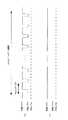
図4は、コントロールデータ領域13cのECCブロックにおいて、先頭付近の更に詳細なデータ構造を示す図である。すなわち、各セクタは、92バイトごとに先頭にシンクコードが挿入されたシンクフレームに区分され、1つのセクタが全部で26個のシンクフレームから構成される。図4においては、第1シンクフレームSF1〜第26シンクフレームSF26として示している。
【0057】
また、各シンクフレームは2つごとに行として組み合わされ、セクタ中の最後の行にPO(Parity Out)パリティが付加されると共に、それぞれの行にはPI(Parity In)パリティが付加される。POパリティとPIパリティは、ECCブロックにおける誤り検査用の外符号として用いられる。
【0058】
そして本実施形態では、図4に示すように、リンクスタートポイントSPからリンクエンドポイントEPまでの範囲をプリ記録領域として定めている。そして、リンクスタートポイントSPは、各ECCブロックにおけるセクタ0の第21シンクフレームSF21の16バイト目に、リンクエンドポイントEPはセクタ2の第9シンクフレームSF9の15バイト目にそれぞれ設定されている。このプリ記録領域においては、DVD−RW10に対し、例えば後述の処理によってエンボスピット列を形成することによりプリ記録データが記録される。あるいは、有機色素記録膜を使用したDVD−Rを用いる場合は、レーザ記録によってプリ記録データを記録してもよい。
【0059】
すなわち、プリ記録データが記録されたプリ記録領域は、ユーザによって後から上書きできない領域となる。特に、コントロールデータ領域13cのディスク製造情報には、DVD−RW10にスクランブルを施す場合に必要な情報を書き込むことができなくなるので、再生のみ可能な他のDVD−ROM等の内容をDVD−RW10に不正コピーした場合も、スクランブルの解除は困難となる。従って、DVD−RW10を不正コピーのための情報記録媒体として利用することができなくなる。一方、コピー禁止ではなくスクランブルも施されていないコンテンツであれば、他のDVD−ROM等から本実施形態に係るDVD−RW10に正常にコピーすることが可能である。この場合は、プリ記録領域のデータ内容とは無関係にDVD−RW10に記録したコンテンツを再生できるからである。
【0060】
なお、本実施形態におけるプリ記録領域は、上述の範囲に限定されるものではなく、スクランブルに関するデータ部分など、不正コピーを防止するために効果がある範囲であれば、自由に設定可能である
ここで、図4に示すように、プリ記録領域のリンクスタートポイントSPとリンクエンドポイントEPは、各シンクフレームの先頭にあるシンクコードに重ならないような配置にしている。これは、プリ記録領域のリンキング部分の境界が各シンクフレームの境界に一致すると、シンクコードが確実に捕えられず、結果的にシンクフレームの境界を誤るおそれがあるためである。
【0061】
なお、プリ記録データの内容は特に限定されず、予め定められたデータ列であれば、自由に設定可能である。例えば、オールゼロとしてもよい。ただし、プリ記録データにおいてPOパリティとPIパリティに対応するデータ部分では、以下に説明する配慮が必要となる。
【0062】
すなわち、図4に示すように、プリ記録領域にプリ記録データを記録する場合、パリティの不整合が問題となる。特に、プリ記録領域内のPOパリティのデータ部分は、図4におけるプリ記録領域外の対応するデータ内容が変更されたときは適正な値に修正する必要があるのに対し、プリ記録領域にいったん記録されたPOパリティは変更できないため、このような不整合が生じるのである。
【0063】
本実施形態においては、図4に示すECCブロック内で、ワーストケースとして計4つの行で不整合を生じ、パリティエラーを生じる可能性がある。具体的には、
(1)リンクスタートポイントSPを含む行
(2)セクタ0の最後のPOパリティ行
(3)セクタ1の最後のPOパリティ行
(4)リンクエンドポイントEPを含む行
である。
【0064】
ここで、(1)、(4)のように、プリ記録領域のリンキング部分でエラーを生じるのは、記録タイミングのずれに起因する。すなわち、再生用クロックの位相が最大180°ずれたとき、その復帰には1.8シンクフレーム相当分の時間がかかり、データの欠落によりPIパリティエラーを引き起こす可能性があるためである。
【0065】
なお、プリ記録データを記録する際にパリティの整合性をとったとしても、コントロールデータ領域13cにおいては、当初は不確定なデータも存在するため、後から不整合を生じる可能性が大きい。また、上述のワーストケースでは、(2)と(3)のPOパリティ行では、数バイトのバイトエラーを生じる可能性があり、PIパリティの訂正を施すことができなくなる可能性が大きい。なお、DVD−RW10の記録フォーマットにおけるPIエラーに対する誤り訂正能力は5バイト分である。これを超えるとPIエラーとなって、(2)と(3)に対応するパリティエラーを引き起こす。
【0066】
一方、ベストケースとしては、(1)と(4)に対応するプリ記録領域のリンキング部分ではエラーを生じない(再生用クロックの位相のずれが小さい場合)。また、(2)と(3)に対応するバイトエラーがPIエラー訂正の範囲内となれば、POパリティ行でもパリティエラーを生じない。結局、ベストケースでは(1)〜(4)の何れのパリティエラーも生じることはない。実際には、ワーストケースとベストケースの中間に分布してパリティエラーを生じることとなる。
【0067】
ところで、DVD−RW10の記録フォーマットにおけるPOパリティの誤り訂正能力はECCブロック内で16行分である。従って、上述のワーストケースとして(1)〜(4)の4行分のPOパリティエラーが生じた場合でも、十分に訂正可能である。上述のワーストケースでは4行分のパリティエラーを生じるため、ECCブロックに対する16行分の訂正能力が実質的に12行分に低下することとなるが、通常の使用範囲内であれば特に問題にはならない。
【0068】
なお、より訂正能力を犠牲にしないために、リンキング部分をPOパリティ行に設けてもよい。プリ記録されたPOパリティ行は、プリ記録されたデータ内容と、後から記録されたデータとの間でECCブロックとしての整合が取れない可能性が高い。そのため、エラーになる可能性が高くなる。また、リンキング部分を含む行は、PIエラーとなる可能性が高い。そこで、リンキング部分をPOパリティ行に設ければ、エラーとなる可能性が高い行数を2行から1行に低減できる点で好ましい。
【0069】
次に、上述のプリ記録データを含むECCブロックのデータ生成方法について考える。なお、ECCブロックのプリ記録データ以外のデータの大部分は、固定値として予め設定しておくことが可能であるが、上述の物理フォーマットに含まれるLast Recorded Addressの値は予め把握しておくことができない。このLast Recorded Addressは、DVD−RW10のデータ領域14に記録済みのデータの範囲における最終のアドレスが記録されるので、DVD−RW10に記録する度に更新されるべきデータである。そこで、本実施形態では、Last Recorded Addressに予め適当な値を入れ(例えばオールゼロ)、ECCブロックの生成を行う。
【0070】
そして、実際のECCブロックの生成方法としては、以下に説明する3通りの方法が考えられる。
【0071】
第1の方法は、ECCブロック中、プリ記録領域を所定のプリ記録データとし、それ以外の部分を上述のデータとしてECCブロックを生成する。そして、後からECCブロックに対しLast Recorded Addressを異なる値として追記する。この場合は、既に説明したように、パリティの不整合を生ずるが、記録フォーマットにおけるエラー訂正能力に依存して、適正な処理が行われる。
【0072】
第2の方法は、第1の方法と同様にいったんECCブロックを生成するが、後からECCブロックを追記する際に、予め把握されるプリ記録データに基づいて、パリティ生成についての逆演算を施し、POパリティの内容を新たに求めて更新した上で、ECCブロックの追記を行うものである。
【0073】
第3の方法は、第1の方法と第2の方法を組み合わせる方法である。すなわち、ECCブロックのうち、パリティの不整合を生ずる部分を予め限定し、その領域では第2の方法による逆演算を施し、それ以外の領域では第1の方法によりECCブロックの追記を行うものである。
【0074】
これら3通りのECCブロックの生成方法は、システムに必要なエラー訂正能力や処理の簡素化等を勘案し、適宜に選択して用いることができる。
(第1の実施形態)
次に、本発明の第1の実施形態について説明する。ここでは、上述のデータ構造を有するDVD−R、DVD−RWを製造する情報記録媒体製造装置としてのカッティング装置について図5〜図7を参照して説明する。第1の実施形態に係るカッティング装置は、本発明のプリ記録領域に対応するエンボスピット列が形成された光ディスクを大量生産するためのスタンパディスクを作製するための装置である。
【0075】
図5は、第1の実施形態に係るカッティング装置の概略構成を示すブロック図である。図5に示すカッティング装置は、ランドデータ発生器20と、パラレル/シリアル変換器21と、プリフォーマット用エンコーダ22と、クロック信号発生部23と、レーザ発生装置24と、光変調器25と、対物レンズ26と、スピンドルモータ29と、回転検出器30と、回転サーボ回路31と、送りユニット32と、位置検出器33と、送りサーボ回路34と、CPU40と、グルーブデータ発生器50と、ウォブリング信号発生器51と、可変利得アンプ52と、スイッチ53とにより構成されている。
【0076】
また、スタンパディスクは、ガラス基板27と、このガラス基板27上にコーティングされたレジスト28とにより構成されている。レジスタ28は、後述の光ビームBが照射されることにより感光され、光ビームBの強度の変化に対応した形状のピットが形成されるものである。
【0077】
図5において、ランドデータ発生器20は、CPU40の制御の下、ランドトラック、及び、予め各種制御信号を記録するために形成されるランドプリピットに対応するパラレルデータを出力する。出力されたパラレルデータは、パラレル/シリアル変換器21によってシリアルデータに変換される。そして、このシリアルデータは、プリフォーマット用エンコーダ22に入力され、クロック信号発生部23から供給されるプリフォーマッティング用のクロック信号に基づいて、ランドトラックやプリピットを実際にスタンパディスク上に形成するためのランドデータ信号SLが生成され、光変調器25に出力される。
【0078】
一方、グルーブデータ発生器50は、CPU40の制御の下、グルーブトラック、及びエンボスピット列として形成されるプリ記録データを含むグルーブデータを生成し、スイッチ53に対する制御信号として出力する。
【0079】
また、ウォブリング信号発生器51は、グルーブトラックに微少なうねりを与えるためのウォブリング信号を発生する。そして、ウォブリング信号は、可変利得アンプ52によりウォブリング信号にCPU40の制御に従って適当なゲインを付与された後、スイッチ53に出力される。
【0080】
このように、本実施形態において可変利得アンプ52を設けてウォブリング信号のレベルを可変する構成としたのは、グルーブトラックのうち、プリ記録データに対応するエンボスピット列が形成されている部分のウォブリングを大きな振幅にするためである。すなわち、ウォブリングが施されたスタンパディスクにより製造された光ディスクを再生する際、エンボスピット列の分だけグルーブトラックの面積が小さくなる。そのため、グルーブトラックからの反射光のレベルが小さくなって、ウォブリング信号を含むプッシュプル信号のレベルが低下し、ウォブリング信号の抽出に支障を来す。その対策として、プッシュプル信号のレベルの低下を、可変利得アンプ52によるゲインの調整により打ち消し、ウォブリング信号のレベルを補償するようにしたものである。
【0081】
上述のようにスイッチ53では、ゲインを付与されたウォブリング信号とグランドレベルが入力され、グルーブデータ発生器50から出力されるグルーブデータに基づいて切り換え制御が行われる。これにより、実際にスタンパディスク上にグルーブトラックの形状を形成するためのグルーブデータ信号SGを光変調器25に出力する。
【0082】
レーザ発生装置24は、スタンパディスクに対してランドトラックとグルーブトラックを形成するための光ビームBを出射する。出射された光ビームBは、光変調器25によって上述のランドデータ信号SL及びグルーブデータ信号SGを用いて変調を施され、対物レンズ26を介してスタンパディスク上に集光される。
【0083】
このとき、スピンドルモータ29がスタンパディスクを回転させると共に、回転検出器30がスタンパディスクの回転を検出する。これにより、回転サーボ回路31がスタンパディスクの回転を制御すると共に、回転に同期した回転パルスを出力する。
【0084】
位置検出器33は、送りユニット32の位置を検出し、その検出信号を送りサーボ回路34に出力する。送りサーボ回路34は、位置検出器33からの検出信号に基づいて、送りユニット32の位置情報を取得し、これにより送りユニット32の移動をサーボ制御する。
【0085】
以上のような動作が行われることにより、螺旋状のトラックとエンボスピット列に対応する凹凸形状がスタンパディスク上に形成され、光ディスク製造のための抜き型としてのスタンパディスクが完成することになる。その後は、スタンパディスクを用いたレプリケーションプロセスが実行され、本発明に係るエンボスピット列を有するレプリカディスクとしての光ディスクが大量生産される。
【0086】
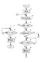
次に、第1の実施形態に係るカッティング装置において行われるスタンパディスクのカッティング処理について、図6及び図7に示すフローチャートを参照して説明する。なお、この処理は図示しないメモリ手段に格納される制御プログラムに従って、主にCPU40により行われる。
【0087】
図6に示すように、カッティング装置における処理が開始されると、ランドデータ発生器20とグルーブデータ発生器50に対する初期化が行われ(ステップS1)、所定のデータが設定される。次いで、位置検出器33から出力される検出信号に基づいて、光ビームのディスク半径方向での照射位置を検出する(ステップS2)。
【0088】
このとき、ステップS2において検出された照射位置に基づいて、スタンパディスク上の記録終了位置に達したか否かを判定する(ステップS3)。すなわち、照射される光ビームがスタンパディスクのリードアウト領域15の最外周部に位置するかどうかが判定される。
【0089】
その結果、記録終了位置に達したと判定されると(ステップS3;YES)、回転サーボ回路31から出力される回転パルスの検出を行う(ステップS4)。すなわち、判定された記録終了位置において、情報の記録終了位置に対応する1周分のプリピットが記録されたかどうかが判定するものである。
【0090】
ステップS4における処理は、回転パルスが検出されるまで継続され(ステップS4;NO)、回転パルスが検出されたときは(ステップS4;YES)、CPU40からランドデータ発生器20とグルーブデータ発生器50に対し、書き込みの終了を指示する制御信号を送出する。これにより、ランドデータとグルーブデータを用いた書き込み処理が終了する。
【0091】
一方、ステップS3の判定の結果、記録終了位置に達していない場合は(ステップS3;NO)、スタンパディスク上の記録開始位置に達したか否かを判定する(ステップS6)。すなわち、照射される光ビームがスタンパディスクのリードイン領域13の最内周部に位置するかどうかが判定される。
【0092】
その結果、記録開始位置に達したと判定されると(ステップS6;YES)、回転サーボ回路31から出力される回転パルスの検出を行う(ステップS7)。すなわち、判定された記録開始位置において、スタンパディスクの1周につき1箇所設定されている周方向の記録基準位置に達したかどうかを判定する。
【0093】
ステップS7における処理は、回転パルスが検出されるまで継続され(ステップS7;NO)、回転パルスが検出されたときは(ステップS7;YES)、CPU40からランドデータ発生器20とグルーブデータ発生器50に対し、書き込みの開始を指示する制御信号を送出する。これにより、ランドデータとグルーブデータを用いた書き込み処理の準備が整い、ステップS2以降の処理を繰り返す。
【0094】
一方、ステップS6の判定の結果、記録開始位置に達していない場合は(ステップS6;NO)、ステップS11(図7)に移行する。図7に示すように、ステップS11では、ステップS2において検出された照射位置に基づいて、スタンパディスク上において基準とすべき所定位置に達したか否かを判定する。この所定位置はスタンパディスク上のリードイン領域13に予め設定されており、これを基準として後述のデータ書き込みの位置が判断できる。
【0095】
その結果、まだ所定位置に達していないと判定されると(ステップS11;NO)、ステップS2に戻って同様の処理を繰り返す。一方、所定位置に達していると判定されると(ステップS11;YES)、回転サーボ回路31から出力される回転パルスの検出を行い(ステップS12)、スタンパディスクの1周分において上記所定位置に対応するタイミングを判別する。ステップS12の処理は、回転パルスが検出されるまで継続される(ステップS12;NO)。
【0096】
ステップS12において回転パルスが検出されると(ステップS12;YES)、CPU40が制御する計時手段を用いて計時を開始する(ステップS13)。すなわち、上記所定位置を基準として、本実施形態に係るプリ記録データのリンクスタートポイントSPに達するタイミングを判別するための計時を行うものである。
【0097】
そして計時の結果、予め設定された所定時間が経過したか否かを判断する(ステップS14)。この所定時間は、上記基準位置とリンクスタートポイントSPとの関係から予め把握できる。ステップS14の判断の結果、所定時間がまだ経過していない場合(ステップS14;NO)、経過するまで待ち続ける。
【0098】
一方、ステップS14の判断の結果、所定時間が経過した場合(ステップS14;YES)、プリ記録データに対応するグルーブデータ発生器50からのデータ発生を指示する(ステップS15)。すなわち、プリ記録データに応じた凹凸形状を持つエンボスピット列をスタンパディスクに形成するため、グルーブデーからプリ記録データの出力を開始する。
【0099】
続いて、可変利得アンプ52に対してゲインの増加を指示する(ステップS16)。これは上述したように、スタンパディスク上のエンボスピット列が形成された部分でのウォブリング振幅の相対的な低下を、ウォブリング信号に対するゲインを増大させて補償するものである。なお、通常時に比べ、可変利得アンプ52のゲインを概ね2倍程度に増加することが望ましい。
【0100】
そして、プリ記録データに対応するエンボスピット列の形成が終了したか否かを判断する(ステップS17)。この段階では、光ビームがスタンパディスク上のリンクエンドポイントEPに達していることになる。ステップS14の判断の結果、まだエンボスピット列の形成が終了していない場合(ステップS17;NO)、同様の処理を継続する。
【0101】
一方、エンボスピット列の形成が終了した場合(ステップS17;YES)、ステップS16において増加させた可変利得アンプ52に対し、ゲインの減少を指示して通常時のゲインに戻す(ステップS18)。これにより、第1の実施形態に係るスタンパディスクに対するエンボスピット列の形成を終えることになる。
【0102】
以上説明したように、第1の実施形態に係る情報記録媒体製造装置によれば、カッティングされたスタンパディスクのプリ記録領域には、プリ記録データに対応するエンボスビット列が形成される。よって、このスタンパディスクを用いて製造されたDVD−RW等の光ディスクにも同様のエンボスピット列が形成されることになる。そのため、製造されたDVD−RW等に、コンテンツが記録された他のDVD−ROMの内容をコピーしようとする場合、プリ記録領域にはコピーすることができない。例えば、スクランブルに関するキーデータなどは欠落することになり、適正にコンテンツが再生できなくなるので、不正コピーを有効に防止することができる。
(第2の実施形態)
次に、本発明の第2の実施形態について説明する。ここでは、記録情報を1回書き込み可能なDVD−Rに対する記録と再生を行う情報記録再生装置について図8〜図11を参照して説明する。
【0103】
図8は、第2の実施形態に係る情報記録再生装置の概略構成を示すブロック図である。図8に示す情報記録再生装置は、ピックアップ60と、再生増幅器61と、デコーダ62と、プリピット信号デコーダ63と、スピンドルモータ64と、サーボ回路65と、CPU66と、エンコーダ67と、パワー制御回路68と、レーザ駆動回路69と、インターフェース70と、ウォブリング信号抽出部72と、プリ記録データ発生器73と、スイッチ74とを備えている。また、インターフェース70を介して外部のホストコンピュータ71が接続され、この情報記録再生装置に対して記録すべきディジタルデータが入力される構成となっている。
【0104】
また、図8に示す情報記録媒体としてのDVD−R11は、例えば有機色素記録膜を使用した光ディスクが用いられる。基本的な上述のDVDフォーマットに従った構造を有し、グルーブトラックにはウォブリングが施されると共に、ランドトラックにはプリピットがプリフォーマットされている。ただし、第1の実施形態で述べたような、プリ記録データとしてのエンボスピット列は、まだ形成されていないものとする。
【0105】
図8において、ピックアップ60は、図示しないレーザダイオード、偏光ビームスプリッタ、対物レンズ、ディテクタ等を含み、光ビームBをDVD−R11の情報記録面に照射して記録すべきデータを1回だけ記録すると共に、光ビームBの反射光に基づく検出信号を出力する。
【0106】
再生増幅器61は、ピックアップ60から出力された検出信号を増幅すると共に、プリピットに対応するプリピット信号を出力する。
【0107】
デコーダ62は、増幅された検出信号に対して8−16復調及びデインターリーブを施し、復調信号を出力する。また、プリピット信号デコーダ13は、プリピット信号をデコードしてプリピットのパターンに対応するディジタルデータを出力する。
【0108】
サーボ回路65は、デコーダ62からの復調信号に基づいて、ピックアップ60におけるフォーカスサーボ制御とトラッキングサーボ制御を行う。また、サーボ回路65は、後述のウォブリング信号に基づいてスピンドルモータ64の回転を制御するための制御信号を出力する。
【0109】
CPU66は、情報記録再生装置全体を総括的に制御すると共に、デコーダ62とプリピット信号デコーダ63からそれぞれ出力信号を取得し、DVD−R11に対する書き込み及び再生の動作を制御する。
【0110】
エンコーダ67は、図示しないECCジェネレータ、8−16変調部、スクランブラ等を含み、再生時のエラー訂正単位であるECCブロックを構成し、ECCブロックに対してインターリーブ、8−16変調及びスクランブル処理を施して変調信号を生成する。
【0111】
パワー制御回路68は、エンコーダ67から出力された変調信号に基づいて、ピックアップ60内のレーザダイオードのパワー制御を行う。
【0112】
レーザ駆動回路69は、光ビームBを出射させるため、パワー制御回路68の制御の下、ピックアップ60のレーザダイオードを駆動する。
【0113】
インターフェース70は、ホストコンピュータ71から送信されるディジタルデータを情報記録再生装置に取り込むためのインターフェース動作を行う。
【0114】
ウォブリング信号抽出部72は、再生増幅器61から出力されるプリピット信号に含まれるグルーブトラックのウォブリング信号を抽出し、サーボ回路65に出力する。
【0115】
プリ記録データ発生器73は、本実施形態に係るDVD−R11のプリ記録領域に書き込むためのプリ記録データに対応するディジタルデータを発生し、スイッチ74を介してエンコーダ67に出力する。
【0116】
スイッチ74は、CPU66の制御によって、エンコーダ67に出力される信号を、通常の記録時はホストコンピュータ71側に、プリ記録時はデータ発生器73側になるように経路を切り換える。
【0117】
次に、第2の実施形態に係る情報記録再生装置において行われる記録処理について、特にレーザパワーの制御に着目し、図9〜図11を参照して説明する。図9は、DVD−R11に対するプリ記録データのレーザ記録による記録処理を示すフローチャートである。図10は、プリ記録データを記録済みのDVD−R11に対するデータ記録処理を示すフローチャートである。また、図11は、レーザパワーの制御を行うため、パワー制御回路68において用いられる2種のパターンを示す図である。なお、図9及び図10に示す処理は、メモリ手段に格納される制御プログラムに従って、主にCPU60により行われる。
【0118】
ここでは、情報記録再生装置において、エンボスピット列が形成されていないDVD−R11がセットされた状態で、リードイン領域13へのプリ記録データの書き込みを行う場合の説明を行う。従って、プリ記録データに先立って記録すべきデータのリードイン領域13への書き込みが開始された状況を考える。
【0119】
図9に示すように、処理が開始されると、光ビームBの照射位置に基づいて、DVD−R11上において基準とすべき所定のアドレスに達したか否かを判定する(ステップS21)。この所定のアドレスはDVD−R11上のリードイン領域13において、例えばプリピットに予め記録されている。よって、記録されているアドレスを読み出すことで、後述のプリ記録データを書き込むべき位置を判断することができる。
【0120】
その結果、まだ所定のアドレスに達していないと判定されると(ステップS21;NO)、ステップS21に戻って同様の処理を繰り返す。一方、所定のアドレスに達していると判定されると(ステップS21;YES)、CPU66が制御する計時手段を用いて計時を開始する(ステップS22)。すなわち、上記所定のアドレスを基準位置として、本実施形態に係るプリ記録データのリンクスタートポイントSPに対応するスタートアドレスに達するタイミングを判別するための計時を行うものである。
【0121】
そして、計時の結果、予め設定された所定時間が経過したか否かを判断する(ステップS23)。この所定時間は、上記基準となるアドレスとスタートアドレスとの関係から予め把握できる。ステップS23の判断の結果、所定時間がまだ経過していない場合は(ステップS23;NO)、経過するまで待ち続ける。
【0122】
一方、ステップS23の判断の結果、所定時間が経過した場合は(ステップS23;YES)、スイッチ74を制御して、プリ記録データが出力されるように切り換える。(ステップS24)。すなわち、ホストコンピュータ71から出力されるコントロールデータ領域13cに対するディジタルデータから、プリ記録データ発生器73から出力されるプリ記録データへと接続を切り換える。この切り換えのタイミングは、コントロールデータ領域13cにおけるリンクスタートポイントSPに一致することになる。
【0123】
次いで、プリ記録データの記録が終了したか否かを判断する(ステップS25)。この終了のタイミングは、コントロールデータ領域13cにおけるリンクエンドポイントEPに一致することになる。
【0124】
なお、図9では1回のプリ記録データの記録を説明したが、実際には192個のECCブロックにわたって同様の処理を繰り返すことになる。
【0125】
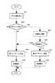
次に、情報記録再生装置において、既にプリ記録データが記録済みであるDVD−R11に対し、後からコントロールデータ領域13cにおけるプリ記録データ以外のデータを記録する場合の処理について、図10を用いて説明する。ここでは、対象となるDVD−R11に記録されているプリ記録データは、第1実施形態に係る方法によりエンボスピット列として形成されている場合、あるいは、図9のフローチャートに示される方法によりレーザ記録されている場合の何れであってもよい。
【0126】
図10に示すように、情報記録再生装置における記録処理が開始されると、対象となるDVD−R11にプリ記録データが、エンボスピット列を用いて形成されているか、又はレーザ記録により書き込まれているかの何れであるかを示すフラグを読み取る(ステップS31)。すなわち、上述したように、第2の実施形態においてはDVD−R11に記録されるプリ記録データとして、エンボスピット列による場合とレーザ記録による場合の2種があるため、コントロールデータ領域13cへの書き込みに際し、これを区別する手段としてDVD−R11にフラグを設けたものである。例えば、このフラグは、コントロールデータ領域13cの所定の領域に割り当てることができる。
【0127】
次いで、読み取ったフラグから、DVD−R11のプリ記録データの記録方法に応じて、行うべき処理を判断する(ステップS32)。ステップS32の判断の結果、DVD−R11にはエンボスピット列ではなくレーザ記録によりプリ記録データが書き込まれている場合は(ステップS32;NO)、パワー制御回路68におけるレーザパワー制御のパターンを、図11(a)に示す第1のパターンに設定する(ステップS33)。
【0128】
そして、第1のパターンを用いて、DVD−R11に対する実際の記録動作が行われ(ステップS34)、記録後に処理を終える。図11(a)に示すように、制御されるレーザパワーには、データを再生するための再生パワーとデータを記録するための記録パワーがある。レーザパワーの基準となるDCレベル、再生パワー、記録パワーの順に大きなパワーとなっていく。第1のパターンによれば、プリ記録データ以外のデータの記録を記録パワーで行う一方、プリ記録データに対する上書きを回避するために、プリ記録データの領域ではレーザパワーを再生パワーに下げるように制御する。なお、再生パワーより小さくしないのは、レーザ制御をより簡易に行うためである。
【0129】
一方、ステップS32の判断の結果、DVD−R11にエンボスピット列が形成されている場合は(ステップS32;YES)、続いてエンボスピット列に対応する検出信号の変調度の測定を行う(ステップS35)。すなわち、上述したように、エンボスピット列に塗布された色素膜の影響によってプリ記録データを再生する際の変調度が低下する場合があるため、後述の対策を施すため、この段階で変調度を確認しておくのである。
【0130】
次いで、測定された変調度の大小を判断する(ステップS36)。その結果、変調度が大きいと判断されたときは(ステップS36;YES)、特に対策は不要であるため、レーザパワー制御のパターンを上述の第1のパターンに設定する(ステップS33)。一方、変調度が小さいと判断されたときは(ステップS36;NO)、その対策として、レーザパワー制御のパターンを、図11(b)に示す第2のパターンに設定する(ステップS37)。
【0131】
そして、第2のパターンを用いて、DVD−R11に対する実際の記録動作が行われ(ステップS38)、記録後の処理を終える。第2のパターンによれば、プリ記録データ以外のデータの記録を記録パワーで行い、同様に、プリ記録データの領域でも記録パワーに保持するように制御する。これにより、エンボスピット列そのものは影響を受けないが、エンボスピット列上の色素膜を除去してプリ記録データを再生する際の変調度を回復することができる。
【0132】
以上説明したように、第2の実施形態に係る情報記録再生装置によれば、当初エンボスビット列が形成されていないDVD−Rに、後からプリ記録データの記録が行われる。そのため、第1実施形態の場合と同様、コンテンツが記録された他のDVD−ROMの内容をコピーしようとする場合、プリ記録領域にはコピーすることができなくなり、不正コピーを有効に防止することができる。
【0133】
【発明の効果】
本発明によれば、情報記録媒体のプリ記録領域にはプリ記録データを記録して、別の記録情報の上書きができないようにしたので、この情報記録媒体に対し、記録フォーマットが共通である再生専用の情報記録媒体の全データをコピーしようとする場合であっても、再生制御に必要な情報が欠落することになるため、不正なコピーを有効に防止することができる。
【図面の簡単な説明】
【図1】本実施形態に係るDVD−RWの情報記録面の構成を示す図である。
【図2】本実施形態に係るDVD−RWのリードイン領域の構造を示す図である。
【図3】コントロールデータ領域において、先頭のECCブロックのデータ構造を示す図である。
【図4】コントロールデータ領域のECCブロックの先頭付近における詳細なデータ構造を示す図である
【図5】第1の実施形態に係るカッティング装置の概略構成を示すブロック図である。
【図6】第1の実施形態において、スタンパディスクのカッティング処理を説明するフローチャートである。
【図7】第1の実施形態において、スタンパディスクのカッティング処理のうち、記録開始位置に達していない場合の処理を説明するフローチャートである。
【図8】第2の実施形態に係る情報記録再生装置の概略構成を示すブロック図
【図9】第2の実施形態において、DVD−Rに対するプリ記録データの記録処理を説明するフローチャートである。
【図10】第2の実施形態においてプリ記録データを記録済みのDVD−Rに対するデータ記録処理を説明するフローチャートである
【図11】パワー制御回路において用いられる2種のレーザパワー制御用の2種のパターンを示す図である。
【符号の説明】
10…DVD−RW
11…DVD−R
12…クランプ孔
13…リードイン領域
13a…オールゼロ領域
13b…リファレンスコード領域
13c…コントロールデータ領域
14…データ領域
15…リードアウト領域
20…ランドデータ発生器
21…パラレル/シリアル発生器
22…プリフォーマット用エンコーダ
23…クロック信号発生部
24…レーザ発生装置
25…光変調器
26…対物レンズ
27…ガラス基板
28…レジスト
29…スピンドルモータ
30…回転検出器
31…回転サーボ回路
32…送りユニット
33…位置検出器
34…送りサーボ回路
40…CPU
50…グルーブデータ発生器
51…ウォブリング信号発生器
52…可変利得アンプ
53…スイッチ
61…再生増幅器
62…デコーダ
63…プリピット信号デコーダ
64…スピンドルモータ
65…サーボ回路
66…CPU
67…エンコーダ
68…パワー制御回路
69…レーザ駆動回路
70…インターフェース
71…ホストコンピュータ
72…ウォブリング信号抽出部
73…プリ記録データ発生器
74…スイッチ[0001]
BACKGROUND OF THE INVENTION
TECHNICAL FIELD The present invention relates to an information recording medium manufacturing apparatus, an information recording medium, an information recording apparatus, and an information recording method capable of effectively preventing unauthorized copying of recorded information recorded on an information recording medium such as a DVD. Belonging to.
[0002]
[Prior art]
In recent years, a large-capacity optical disk represented by a DVD is rapidly spreading as an information recording medium for recording various contents such as video and audio. Since these contents recorded as digital data on an information recording medium such as a DVD are generally protected by copyright, it is necessary to take some measures to prevent unauthorized copying to other recording media. .
[0003]
As such a countermeasure, there is known a method of performing scrambling using key data written in a predetermined area when content is reproduced from an information recording medium. For example, in the case of the DVD format, such key data is written together with copy prohibition information as control data in the lead-in area. In the recording / reproducing apparatus, when the information recording medium in which copying is prohibited is read, the copy prohibition information is determined. For this reason, the scramble of the information recording medium is not released, and unauthorized copying of the information recording medium can be prevented.
[0004]
[Problems to be solved by the invention]
However, for the information recording medium for which copying is prohibited as described above, the RF signal is read from a DVD-ROM or the like, regardless of the contents of the copy prohibition information and the scramble key data, instead of using normal reproduction processing. In some cases, the hard copy may be made on another information recording medium as a whole. Recently, DVD recordable (DVD-R) that can be recorded only once and DVD rewritable (DVD-RW) that can be repeatedly recorded have been realized, so the above-described RF signal is written to DVD-R or DVD-RW. As a result, an optical disc having the same data content as that of the original information recording medium can be produced, and as a result, the copyright is infringed.
[0005]
Therefore, the present invention has been made in view of the above-described problems, and even when an RF signal is read from an information recording medium and hard copying is attempted, illegal copying of the information recording medium can be effectively prevented. An object of the present invention is to provide a writable information recording medium, an information recording medium manufacturing apparatus for manufacturing the information recording medium, an information recording apparatus for recording on the information recording medium, and an information recording method.
[0006]
[Means for Solving the Problems]
In order to solve the above-mentioned problem, the cutting device according to
In order to solve the above problem, the cutting device according to
[0007]
Claims4The cutting device according to
[0011]
[0012]
Here, when an information recording medium having a lead-in area including a control data area is used, it is desirable to set the pre-recording area arrangement in the control data area. As a result, overwriting of various control information can be appropriately prevented.
[0016]
To solve the above problem,Claim27The information recording medium described in (1) includes a data area in which an information recording track capable of recording record information in a predetermined format is formed, and an area in which reproduction control information for controlling copy prevention of the record information is to be recorded. An area including an area allocated to the reproduction control information in the format,Data that makes it difficult to unscramble the recorded informationA pre-recording area in which pre-recorded data is formed as an embossed pit row, and the embossed pit row is wobbled.
In order to solve the above problem, the information recording medium according to claim 28 is for controlling a data area in which an information recording track capable of recording record information in a predetermined format is formed, and copy prevention of the record information. The area to be recorded with the reproduction control information is an area including an area allocated to the reproduction control information in the format, and pre-recording data composed only of zero is formed as an embossed pit row And the embossed pit row is wobbled.
[0017]
Also,To solve the above problem,Claim31The information recording medium described in claim27 or 28The information recording medium according to
[0021]
Claim27To claims33According to the invention described in FIG.,In advance, Pre-recording that is either data that makes it difficult to de-scramble the recorded information or consists of only zerosData is recorded as an embossed pit sequence. Therefore, it is impossible to overwrite other recorded information in this portion. In particular, even when attempting to copy all data of a read-only information recording medium having a common format to this information recording medium, reproduction control information for preventing copy of scramble key data, etc. is missing. Therefore, unauthorized copying can be effectively prevented. In addition, since the embossed pit string formed in the pre-recording area in the information recording medium is wobbled, the wobble signal is surely acquired when reproducing the recorded information recorded on the information recording medium. It becomes possible.
[0022]
Here, when the information recording medium has a configuration including a lead-in area including a control data area, it is desirable to set the arrangement of the pre-recording area in the control data area. As a result, overwriting of various control information can be appropriately prevented.
[0025]
To solve the above problem,Claim5The information recording apparatus described in 1 is an information recording apparatus that records recording information by irradiating an information recording medium with a light beam with a predetermined power on the basis of a predetermined format, and prevents the recording information from being copied. An area discriminating unit for discriminating a pre-recording area including an area allocated to the reproduction control information in the format as an area where reproduction control information for control is to be recorded, and for the discriminated pre-recording area ,Data that makes it difficult to unscramble the recorded information.Prerecorded data writing means for writing prerecorded data in advance by laser recording.
In order to solve the above problem, an information recording apparatus according to
[0026]
According to the present invention, prior to recording on the information recording medium, the pre-recording area is determined and the pre-recording area is determined.Either data that makes it difficult to unscramble the recorded information, or consists of only zerosThe prerecorded data is written in advance by laser recording. Then, for example, in an information recording medium in which writing of information is limited to one time, it becomes impossible to overwrite another recording information in the pre-recording area. In particular, even when attempting to copy all data of a read-only information recording medium having a common format to this information recording medium, reproduction control information for preventing copy of scramble key data, etc. is missing. Therefore, unauthorized copying can be effectively prevented.
[0027]
To solve the above problem,Claim9The information recording apparatus described in 1 is an information recording apparatus that records recording information by irradiating an information recording medium with a predetermined power with a predetermined format according to a predetermined format, and controls copy prevention of the recording information An area discriminating unit for discriminating a pre-recording area including an area allocated to the reproduction control information in the format as an area for recording the reproduction control information forThis is data that makes it difficult to unscramble the recorded information.Determination means for determining whether pre-recorded data is formed as an embossed pit row or whether the pre-recorded data is written by laser recording, and confirms the degree of modulation of the detection signal based on the pre-recorded data When recording the recording information with the modulation degree confirmation means, when the determination means determines that the embossed pits are formed and the modulation degree confirmation means confirms that the modulation degree is small, Power control means for maintaining the light beam at the recording power in the pre-recording area.
In order to solve the above-described problem, an information recording apparatus according to
[0028]
Also,To solve the above problem,The information recording device according to
[0031]
Claim9To claims13According to the invention described inEither the data that makes it difficult to unscramble the recorded information, or consists of only zerosWhen performing recording on an information recording medium on which pre-recorded data has already been recorded, it is determined whether the pre-recorded data is recorded by an embossed pit row or laser recording, for example, by reading a predetermined flag, Further, the degree of modulation of the detection signal based on the embossed pit row is also confirmed. Then, when the emboss pit is formed and the modulation degree is small, control is performed so that the light beam is kept at the recording power, and otherwise the light beam is kept at a predetermined power sufficiently lower than the recording power such as reproduction power. Therefore, it is possible to effectively prevent a decrease in the degree of modulation in the detection signal of the pre-record data due to the influence of the dye film applied to the embossed pit row.
[0032]
Here, when an information recording medium having a lead-in area including a control data area is used, it is desirable to set the pre-recording area arrangement in the control data area. As a result, overwriting of various control information can be appropriately prevented.
[0035]
To solve the above problem,Claim18Is an information recording method for recording recording information by irradiating an information recording medium with a predetermined power with a predetermined power in a predetermined format, and controls the copy prevention of the recording information For determining the pre-recording area including the area assigned to the playback control information in the format, and the pre-recording determined in the area determining process In the area,Data that makes it difficult to unscramble the recorded information.And a pre-record data writing step for pre-recording data to be written in advance by laser recording.
In order to solve the above-described problem, an information recording method according to claim 19 is an information recording method for recording recorded information by irradiating an information recording medium with a predetermined power with a predetermined power in a predetermined format. An area discriminating step for discriminating a pre-recording area including an area allocated to the reproduction control information in the format, as an area where reproduction control information for controlling copy prevention of the recording information is to be recorded; A pre-recording data writing step of pre-recording pre-recording data composed of only zeros by laser recording in the pre-recording region determined in the region determining step.
[0036]
Also,To solve the above problem,Claim22Is an information recording method for recording recording information by irradiating an information recording medium with a predetermined power with a predetermined power in a predetermined format, and controls the copy prevention of the recording information An area determination step for determining a pre-recording area including an area allocated to the reproduction control information in the format, and an area for recording the reproduction control information for the determined pre-recording area;This is data that makes it difficult to unscramble the recorded information.A determination step for determining whether the pre-record data is formed as an embossed pit row or whether the pre-record data is written by laser recording, and confirming the magnitude of the modulation degree of the detection signal based on the pre-record data When the modulation degree confirmation step and the recording information are recorded, it is determined that the embossed pits are formed in the determination step and the modulation degree confirmation step confirms that the modulation degree is small. Comprises a power control step of maintaining the light beam at a recording power in the pre-recording area.
In order to solve the above problems, an information recording method according to
[0037]
Also,To solve the above problem,Claim26The information recording method described in claim22Thru25The information recording method according to any one of the preceding claims, wherein the information recording medium has a lead-in area preceding a data area in which recording information is recorded, and the pre-recording area is a control data area of the lead-in area. It is located inside.
[0043]
Claim22To claims26According to the invention described in claim9To claims13As a result of the operation similar to that described above, it is possible to effectively prevent a decrease in the degree of modulation in the detection signal of the pre-record data due to the influence of the dye film applied to the embossed pit rows.
[0044]
In addition, overwriting of various control information can be appropriately prevented, and for example, illegal copying from an information recording medium in which scramble key data or the like is written in the disc manufacturing information can be effectively prevented.Ru.
[0048]
DETAILED DESCRIPTION OF THE INVENTION
DESCRIPTION OF EXEMPLARY EMBODIMENTS Hereinafter, preferred embodiments of the invention will be described with reference to the drawings. In the following embodiments, an information recording medium manufacturing apparatus that cuts a stamper disk for manufacturing a DVD-R or a DVD-RW, and an information recording / reproducing apparatus that records and reproduces recorded information on a DVD-R. The case where the present invention is applied will be described.
[0049]
First, a DVD-RW recording format according to this embodiment will be described with reference to FIGS. The following description applies similarly to DVD-R.
[0050]
FIG. 1 is a diagram showing a configuration of an information recording surface of a DVD-RW as an information recording medium according to the present embodiment. As shown in FIG. 1, the information recording surface of the DVD-
[0051]
FIG. 2 is a diagram showing the structure of the lead-in
[0052]
In the control data area 13c, 192 consecutive ECC blocks are recorded. That is, the same control information is repeatedly recorded 192 times in the control data area 13c.
[0053]
FIG. 3 is a diagram showing the data structure of the leading ECC block among the 192 ECC blocks included in the control data area 13c. The basic data structure is the same for other ECC blocks. As shown in FIG. 3, the ECC block includes physical format information relating to the type and format of the disc, disc manufacturing information relating to disc manufacture, and reserve information such as content provider information.
[0054]
The ECC block is composed of 16 sectors, sector 0 to
[0055]
In the present embodiment, a predetermined area in the ECC block of the control data area 13c configured as described above is defined as a pre-recording area, and predetermined pre-recording data is formed in the pre-recording area as an embossed pit row, for example. Measures are taken to prevent copying of information recording media.
[0056]
FIG. 4 is a diagram showing a more detailed data structure near the head in the ECC block of the control data area 13c. That is, each sector is divided into sync frames having a sync code inserted at the head every 92 bytes, and one sector is composed of 26 sync frames in total. In FIG. 4, the first sync frame SF1 to the 26th sync frame SF26 are shown.
[0057]
Each sync frame is combined as a row every two, PO (Parity Out) parity is added to the last row in the sector, and PI (Parity In) parity is added to each row. The PO parity and PI parity are used as outer codes for error checking in the ECC block.
[0058]
In this embodiment, as shown in FIG. 4, the range from the link start point SP to the link end point EP is defined as the pre-recording area. The link start point SP is set to the 16th byte of the 21st sync frame SF21 of sector 0 in each ECC block, and the link end point EP is set to the 15th byte of the ninth sync frame SF9 of
[0059]
That is, the pre-recording area where the pre-recording data is recorded is an area that cannot be overwritten later by the user. In particular, information necessary for scrambling the DVD-
[0060]
Note that the pre-recording area in the present embodiment is not limited to the above-described range, and can be freely set as long as it is effective in preventing unauthorized copying, such as a data portion related to scramble.
Here, as shown in FIG. 4, the link start point SP and the link end point EP in the pre-recording area are arranged so as not to overlap the sync code at the head of each sync frame. This is because if the boundary of the linking portion of the pre-recording area coincides with the boundary of each sync frame, the sync code is not reliably captured, and as a result, the sync frame boundary may be erroneous.
[0061]
The content of the pre-record data is not particularly limited, and can be freely set as long as it is a predetermined data string. For example, all zeros may be used. However, in the pre-recorded data, the data portion corresponding to the PO parity and the PI parity needs to be considered as described below.
[0062]
That is, as shown in FIG. 4, when pre-recorded data is recorded in the pre-recording area, parity mismatch becomes a problem. In particular, the data portion of the PO parity in the pre-recording area needs to be corrected to an appropriate value when the corresponding data content outside the pre-recording area in FIG. 4 is changed. Such a mismatch occurs because the recorded PO parity cannot be changed.
[0063]
In the present embodiment, in the ECC block shown in FIG. 4, there is a possibility that a mismatch occurs in a total of four rows as a worst case, resulting in a parity error. In particular,
(1) Line including link start point SP
(2) Last PO parity row in sector 0
(3) Last PO parity row in
(4) Line including link endpoint EP
It is.
[0064]
Here, as shown in (1) and (4), the occurrence of an error in the linking portion of the pre-recording area is caused by a shift in recording timing. That is, when the phase of the reproduction clock is shifted by a maximum of 180 °, it takes a time corresponding to 1.8 sync frames to recover, and there is a possibility of causing a PI parity error due to data loss.
[0065]
Even when parity consistency is taken when pre-record data is recorded, there is a high possibility that inconsistency will occur later in the control data area 13c because there is initially uncertain data. In the worst case described above, the PO parity rows (2) and (3) may cause a byte error of several bytes, and there is a high possibility that the PI parity cannot be corrected. Note that the error correction capability for the PI error in the recording format of the DVD-
[0066]
On the other hand, as a best case, no error occurs in the linking portion of the pre-recording area corresponding to (1) and (4) (when the phase shift of the reproduction clock is small). Further, if the byte error corresponding to (2) and (3) is within the range of PI error correction, no parity error occurs even in the PO parity row. Eventually, none of the parity errors (1) to (4) occur in the best case. Actually, parity errors occur in the middle of the worst case and the best case.
[0067]
By the way, the error correction capability of the PO parity in the recording format of the DVD-
[0068]
Note that a linking portion may be provided in the PO parity row so as not to sacrifice the correction capability. There is a high possibility that the pre-recorded PO parity row cannot be matched as an ECC block between the pre-recorded data content and the data recorded later. This increases the possibility of an error. In addition, a line including a linking portion is likely to cause a PI error. Therefore, it is preferable to provide the linking portion in the PO parity row in that the number of rows that are likely to cause an error can be reduced from 2 rows to 1 row.
[0069]
Next, consider a data generation method of the ECC block including the pre-recorded data described above. Note that most of the data other than the pre-record data of the ECC block can be set in advance as a fixed value, but the value of the Last Recorded Address included in the physical format described above must be grasped in advance. I can't. This Last Recorded Address is data that should be updated each time recording is performed on the DVD-
[0070]
As an actual ECC block generation method, the following three methods can be considered.
[0071]
In the first method, an ECC block is generated with the pre-recording area as predetermined pre-recording data and the other part as the above-mentioned data in the ECC block. Then, the Last Recorded Address is added as a different value to the ECC block later. In this case, as described above, parity mismatch occurs, but appropriate processing is performed depending on the error correction capability in the recording format.
[0072]
In the second method, an ECC block is generated once as in the first method. However, when an ECC block is added later, an inverse operation for parity generation is performed based on pre-recorded data that is grasped in advance. The ECC block is additionally written after the content of the PO parity is newly obtained and updated.
[0073]
The third method is a method of combining the first method and the second method. That is, the portion of the ECC block that causes parity mismatch is limited in advance, the inverse operation is performed by the second method in that region, and the ECC block is additionally written by the first method in other regions. is there.
[0074]
These three ECC block generation methods can be selected and used as appropriate in consideration of error correction capability necessary for the system, simplification of processing, and the like.
(First embodiment)
Next, a first embodiment of the present invention will be described. Here, a cutting apparatus as an information recording medium manufacturing apparatus for manufacturing DVD-R and DVD-RW having the above-described data structure will be described with reference to FIGS. The cutting apparatus according to the first embodiment is an apparatus for producing a stamper disk for mass production of an optical disk on which an embossed pit row corresponding to a pre-recording area of the present invention is formed.
[0075]
FIG. 5 is a block diagram illustrating a schematic configuration of the cutting apparatus according to the first embodiment. A cutting apparatus shown in FIG. 5 includes a
[0076]
The stamper disk is constituted by a glass substrate 27 and a resist 28 coated on the glass substrate 27. The register 28 is sensitized by being irradiated with a light beam B described later, and a pit having a shape corresponding to a change in the intensity of the light beam B is formed.
[0077]
In FIG. 5, the
[0078]
On the other hand, the
[0079]
The
[0080]
As described above, in the present embodiment, the variable gain amplifier 52 is provided so that the level of the wobbling signal is variable. The wobbling of the portion of the groove track where the embossed pit row corresponding to the pre-recorded data is formed is provided. This is to increase the amplitude. That is, when an optical disc manufactured by a wobbling stamper disc is reproduced, the area of the groove track is reduced by the amount of the embossed pit row. For this reason, the level of reflected light from the groove track is reduced, the level of the push-pull signal including the wobbling signal is lowered, and the extraction of the wobbling signal is hindered. As a countermeasure, the decrease in the level of the push-pull signal is canceled by adjusting the gain by the variable gain amplifier 52, and the level of the wobbling signal is compensated.
[0081]
As described above, in the
[0082]
The
[0083]
At this time, the spindle motor 29 rotates the stamper disk, and the
[0084]
The
[0085]
By performing the operation as described above, an uneven shape corresponding to the spiral track and the embossed pit row is formed on the stamper disk, and the stamper disk as a die for manufacturing the optical disk is completed. Thereafter, a replication process using a stamper disk is performed, and an optical disk as a replica disk having an embossed pit array according to the present invention is mass-produced.
[0086]
Next, stamper disc cutting processing performed in the cutting apparatus according to the first embodiment will be described with reference to the flowcharts shown in FIGS. 6 and 7. This process is mainly performed by the
[0087]
As shown in FIG. 6, when the process in the cutting apparatus is started, the
[0088]
At this time, based on the irradiation position detected in step S2, it is determined whether or not the recording end position on the stamper disk has been reached (step S3). That is, it is determined whether the irradiated light beam is located at the outermost peripheral portion of the lead-
[0089]
As a result, if it is determined that the recording end position has been reached (step S3; YES), the rotation pulse output from the
[0090]
The process in step S4 is continued until the rotation pulse is detected (step S4; NO). When the rotation pulse is detected (step S4; YES), the
[0091]
On the other hand, if the result of determination in step S3 is that the recording end position has not been reached (step S3; NO), it is determined whether or not the recording start position on the stamper disk has been reached (step S6). That is, it is determined whether or not the irradiated light beam is located at the innermost periphery of the lead-in
[0092]
As a result, if it is determined that the recording start position has been reached (step S6; YES), the rotation pulse output from the
[0093]
The processing in step S7 is continued until the rotation pulse is detected (step S7; NO). When the rotation pulse is detected (step S7; YES), the
[0094]
On the other hand, if the result of determination in step S6 is that the recording start position has not been reached (step S6; NO), the routine proceeds to step S11 (FIG. 7). As shown in FIG. 7, in step S11, based on the irradiation position detected in step S2, it is determined whether or not a predetermined position to be used as a reference on the stamper disk has been reached. This predetermined position is set in advance in the lead-in
[0095]
As a result, if it is determined that the predetermined position has not yet been reached (step S11; NO), the process returns to step S2 and the same processing is repeated. On the other hand, if it is determined that the predetermined position has been reached (step S11; YES), the rotation pulse output from the
[0096]
When a rotation pulse is detected in step S12 (step S12; YES), time measurement is started using the time measuring means controlled by the CPU 40 (step S13). That is, the time for determining the timing at which the pre-recorded data reaches the link start point SP of the pre-recorded data is determined with the predetermined position as a reference.
[0097]
Then, as a result of the time measurement, it is determined whether or not a predetermined time set in advance has elapsed (step S14). This predetermined time can be grasped in advance from the relationship between the reference position and the link start point SP. If the predetermined time has not yet elapsed as a result of the determination in step S14 (step S14; NO), the process continues to wait until it elapses.
[0098]
On the other hand, if the predetermined time has passed as a result of the determination in step S14 (step S14; YES), the generation of data from the
[0099]
Subsequently, the variable gain amplifier 52 is instructed to increase the gain (step S16). As described above, this compensates for the relative decrease in the wobbling amplitude at the portion where the embossed pit row is formed on the stamper disk by increasing the gain for the wobbling signal. It should be noted that it is desirable to increase the gain of the variable gain amplifier 52 to about twice as compared with the normal time.
[0100]
Then, it is determined whether or not the formation of the emboss pit row corresponding to the pre-record data has been completed (step S17). At this stage, the light beam reaches the link end point EP on the stamper disk. As a result of the determination in step S14, when the formation of the embossed pit row has not been completed yet (step S17; NO), the same processing is continued.
[0101]
On the other hand, when the formation of the embossed pit row is completed (step S17; YES), the variable gain amplifier 52 increased in step S16 is instructed to decrease the gain and returned to the normal gain (step S18). Thereby, the formation of the embossed pit row on the stamper disk according to the first embodiment is finished.
[0102]
As described above, according to the information recording medium manufacturing apparatus according to the first embodiment, the embossed bit string corresponding to the prerecorded data is formed in the prerecorded area of the cut stamper disk. Therefore, a similar emboss pit row is also formed on an optical disc such as a DVD-RW manufactured using this stamper disc. For this reason, when trying to copy the contents of another DVD-ROM on which the content is recorded on a manufactured DVD-RW or the like, it cannot be copied to the pre-recording area. For example, key data related to scramble is lost, and the content cannot be reproduced properly, so that illegal copying can be effectively prevented.
(Second Embodiment)
Next, a second embodiment of the present invention will be described. Here, an information recording / reproducing apparatus that performs recording and reproduction on a DVD-R in which recording information can be written once will be described with reference to FIGS.
[0103]
FIG. 8 is a block diagram showing a schematic configuration of an information recording / reproducing apparatus according to the second embodiment. The information recording / reproducing apparatus shown in FIG. 8 includes a pickup 60, a
[0104]
Further, the DVD-
[0105]
In FIG. 8, a pickup 60 includes a laser diode (not shown), a polarizing beam splitter, an objective lens, a detector, etc., and records the data to be recorded only once by irradiating the information recording surface of the DVD-
[0106]
The
[0107]
The
[0108]
The
[0109]
The
[0110]
The
[0111]
The
[0112]
The
[0113]
The
[0114]
The wobbling
[0115]
The
[0116]
The
[0117]
Next, a recording process performed in the information recording / reproducing apparatus according to the second embodiment will be described with reference to FIGS. FIG. 9 is a flowchart showing a recording process by laser recording of prerecorded data on the DVD-R11. FIG. 10 is a flowchart showing a data recording process for the DVD-
[0118]
Here, a description will be given of the case where pre-recorded data is written to the lead-in
[0119]
As shown in FIG. 9, when the process is started, it is determined based on the irradiation position of the light beam B whether or not a predetermined address to be used as a reference on the DVD-
[0120]
As a result, if it is determined that the predetermined address has not yet been reached (step S21; NO), the process returns to step S21 and the same processing is repeated. On the other hand, if it is determined that the predetermined address has been reached (step S21; YES), the clocking is started using the clocking means controlled by the CPU 66 (step S22). That is, using the predetermined address as a reference position, a time is measured for determining the timing to reach the start address corresponding to the link start point SP of the pre-record data according to the present embodiment.
[0121]
Then, as a result of timing, it is determined whether or not a predetermined time set in advance has elapsed (step S23). This predetermined time can be grasped in advance from the relationship between the reference address and the start address. As a result of the determination in step S23, if the predetermined time has not yet elapsed (step S23; NO), the process continues to wait until it elapses.
[0122]
On the other hand, if the result of determination in step S23 is that a predetermined time has elapsed (step S23; YES), the
[0123]
Next, it is determined whether or not the recording of the pre-record data has been completed (step S25). This end timing coincides with the link end point EP in the control data area 13c.
[0124]
In FIG. 9, the recording of one pre-recording data has been described. However, the same processing is actually repeated over 192 ECC blocks.
[0125]
Next, in the information recording / reproducing apparatus, with respect to the DVD-R11 in which prerecorded data has already been recorded, the processing when data other than the prerecorded data in the control data area 13c is recorded later will be described with reference to FIG. explain. Here, pre-recorded data recorded on the target DVD-
[0126]
As shown in FIG. 10, when the recording process in the information recording / reproducing apparatus is started, pre-recorded data is formed on the target DVD-
[0127]
Next, a process to be performed is determined from the read flag according to the recording method of the pre-record data of the DVD-R 11 (step S32). As a result of the determination in step S32, when prerecorded data is written in the DVD-R11 by laser recording instead of the embossed pit row (step S32; NO), a pattern of laser power control in the
[0128]
Then, the actual recording operation for the DVD-
[0129]
On the other hand, if the result of determination in step S32 is that an embossed pit string is formed on the DVD-R11 (step S32; YES), then the modulation degree of the detection signal corresponding to the embossed pit string is measured (step S35). ). That is, as described above, the degree of modulation when reproducing pre-recorded data may be reduced due to the influence of the dye film applied to the embossed pit row. Confirm it.
[0130]
Next, the magnitude of the measured modulation degree is determined (step S36). As a result, when it is determined that the degree of modulation is large (step S36; YES), since no countermeasure is required, the laser power control pattern is set to the first pattern (step S33). On the other hand, when it is determined that the degree of modulation is small (step S36; NO), the laser power control pattern is set to the second pattern shown in FIG. 11B as a countermeasure (step S37).
[0131]
Then, the actual recording operation for the DVD-
[0132]
As described above, according to the information recording / reproducing apparatus in the second embodiment, pre-recorded data is recorded later on a DVD-R in which an initial embossed bit string is not formed. Therefore, as in the case of the first embodiment, when trying to copy the contents of another DVD-ROM in which content is recorded, it is impossible to copy to the pre-recording area, and illegal copying is effectively prevented. Can do.
[0133]
【The invention's effect】
According to the present invention, since pre-recorded data is recorded in the pre-recording area of the information recording medium so that another recording information cannot be overwritten, reproduction with a common recording format for this information recording medium is possible. Even when all data on a dedicated information recording medium is to be copied, information necessary for reproduction control is lost, so that illegal copying can be effectively prevented.
[Brief description of the drawings]
FIG. 1 is a diagram showing a configuration of an information recording surface of a DVD-RW according to the present embodiment.
FIG. 2 is a diagram showing a structure of a lead-in area of a DVD-RW according to the present embodiment.
FIG. 3 is a diagram illustrating a data structure of a leading ECC block in a control data area.
FIG. 4 is a diagram showing a detailed data structure near the beginning of an ECC block in a control data area.
FIG. 5 is a block diagram showing a schematic configuration of the cutting device according to the first embodiment.
FIG. 6 is a flowchart for explaining stamper disk cutting processing in the first embodiment;
FIG. 7 is a flowchart for explaining processing when the recording start position has not been reached in the stamper disc cutting processing in the first embodiment;
FIG. 8 is a block diagram showing a schematic configuration of an information recording / reproducing apparatus according to a second embodiment.
FIG. 9 is a flowchart illustrating prerecorded data recording processing on a DVD-R in the second embodiment.
FIG. 10 is a flowchart for explaining data recording processing for a DVD-R in which pre-recorded data has been recorded in the second embodiment.
FIG. 11 is a diagram showing two types of patterns for laser power control used in a power control circuit.
[Explanation of symbols]
10 ... DVD-RW
11 ... DVD-R
12 ... Clamp hole
13 ... Lead-in area
13a ... All zero area
13b ... Reference code area
13c: Control data area
14: Data area
15 ... Lead out area
20 ... Land data generator
21 ... Parallel / serial generator
22 ... Preformat encoder
23: Clock signal generator
24 ... Laser generator
25. Optical modulator
26 ... Objective lens
27 ... Glass substrate
28 ... resist
29 ... Spindle motor
30 ... Rotation detector
31 ... Rotary servo circuit
32 ... Feeding unit
33 ... Position detector
34 ... Feed servo circuit
40 ... CPU
50 ... Groove data generator
51 ... Wobbling signal generator
52. Variable gain amplifier
53 ... Switch
61 ... Regenerative amplifier
62. Decoder
63 ... Pre-pit signal decoder
64 ... Spindle motor
65. Servo circuit
66 ... CPU
67 ... Encoder
68 ... Power control circuit
69 ... Laser drive circuit
70 ... Interface
71: Host computer
72. Wobbling signal extraction unit
73 ... Pre-record data generator
74 ... Switch
Claims (40)
Translated fromJapanese前記記録情報のコピー防止を制御するための再生制御情報が記録されるべき領域として、前記フォーマットにおいて前記再生制御情報に割り当てられた領域を含むプリ記録領域に対応した前記スタンパディスク上の範囲を判別する領域判別手段と、
前記判別された前記プリ記録領域の範囲内に、前記記録情報に施されたスクランブルの解除を困難にするデータであるプリ記録データをエンボスピット列として形成するエンボスピット列形成手段と、を備え、
前記エンボスピット列形成手段は、ウォブリングを施しつつ前記エンボスピット列を形成することを特徴とするカッティング装置。A cutting device for cutting a stamper disk used for manufacturing an information recording medium capable of recording record information in a predetermined format,
A range on the stamper disk corresponding to a pre-recording area including an area allocated to the reproduction control information in the format is determined as an area in which reproduction control information for controlling copy prevention of the recorded information is to be recorded. Area discriminating means to perform,
An emboss pit row forming means for forming pre-record data as an emboss pit row within the determined pre-record area within the range of the pre-record area, which makes it difficult to release the scramble applied to the record information,
The embossing pit row forming means forms the embossing pit row while performing wobbling.
前記記録情報のコピー防止を制御するための再生制御情報が記録されるべき領域として、前記フォーマットにおいて前記再生制御情報に割り当てられた領域を含むプリ記録領域に対応した前記スタンパディスク上の範囲を判別する領域判別手段と、
前記判別された前記プリ記録領域の範囲内に、ゼロのみから構成されるプリ記録データをエンボスピット列として形成するエンボスピット列形成手段と、を備え、
前記エンボスピット列形成手段は、ウォブリングを施しつつ前記エンボスピット列を形成することを特徴とするカッティング装置。A cutting device for cutting a stamper disk used for manufacturing an information recording medium capable of recording record information in a predetermined format,
A range on the stamper disk corresponding to a pre-recording area including an area allocated to the reproduction control information in the format is determined as an area in which reproduction control information for controlling copy prevention of the recorded information is to be recorded. Area discriminating means to perform,
An emboss pit row forming means for forming pre-record data consisting of only zero as an emboss pit row within the determined pre-record area,
The embossing pit row forming means forms the embossing pit row while performing wobbling.
前記記録情報のコピー防止を制御するための再生制御情報が記録されるべき領域として、前記フォーマットにおいて再生制御情報に割り当てられた領域を含むプリ記録領域を判別する領域判別手段と、
前記判別された前記プリ記録領域に対して、前記記録情報に施されたスクランブルの解除を困難にするデータであるプリ記録データをレーザ記録により予め書き込むプリ記録データ書き込み手段と、
を備えることを特徴とする情報記録装置。An information recording apparatus for recording information by irradiating a light beam with a predetermined power on an information recording medium based on a predetermined format,
Area discriminating means for discriminating a pre-recording area including an area assigned to the reproduction control information in the format as an area to be recorded with reproduction control information for controlling copy prevention of the recording information;
Pre-record data writing means for pre-recording pre-record data, which is data that makes it difficult to release the scramble applied to the record information, to the determined pre-record area by laser recording;
An information recording apparatus comprising:
前記記録情報のコピー防止を制御するための再生制御情報が記録されるべき領域として、前記フォーマットにおいて再生制御情報に割り当てられた領域を含むプリ記録領域を判別する領域判別手段と、
前記判別された前記プリ記録領域に対して、ゼロのみから構成されるプリ記録データをレーザ記録により予め書き込むプリ記録データ書き込み手段と、
を備えることを特徴とする情報記録装置。An information recording apparatus for recording information by irradiating a light beam with a predetermined power on an information recording medium based on a predetermined format,
Area discriminating means for discriminating a pre-recording area including an area assigned to the reproduction control information in the format as an area to be recorded with reproduction control information for controlling copy prevention of the recording information;
Pre-recording data writing means for pre-recording pre-recording data composed of only zero with respect to the determined pre-recording area by laser recording;
An information recording apparatus comprising:
前記記録情報のコピー防止を制御するための再生制御情報を記録すべき領域として、前記フォーマットにおいて前記再生制御情報に割り当てられた領域を含むプリ記録領域を判別する領域判別手段と、
前記判別されたプリ記録領域に、前記記録情報に施されたスクランブルの解除を困難にするデータであるプリ記録データがエンボスピット列として形成されているか、又は、該プリ記録データがレーザ記録により書き込まれているかを判定する判定手段と、
前記プリ記録データに基づく検出信号の変調度の大小を確認する変調度確認手段と、
前記記録情報を記録する際、前記判定手段により前記エンボスピットが形成されていると判定されると共に前記変調度確認手段により前記変調度が小さいと確認された場合は、前記プリ記録領域において前記光ビームを記録パワーに保つパワー制御手段と、
を備えることを特徴とする情報記録装置。An information recording apparatus for recording recorded information by irradiating an information recording medium with a predetermined power with a predetermined power in a predetermined format,
Area discriminating means for discriminating a pre-recording area including an area allocated to the reproduction control information in the format as an area to record reproduction control information for controlling copy prevention of the recording information;
In the discriminated pre-recording area, pre-recording data that is data that makes it difficult to release the scramble applied to the recording information is formed as an embossed pit row, or the pre-recording data is written by laser recording Determining means for determining whether or not
A modulation degree confirmation means for confirming the magnitude of the modulation degree of the detection signal based on the pre-record data;
When recording the recording information, if the determination means determines that the embossed pits are formed and the modulation degree confirmation means confirms that the modulation degree is small, the light is recorded in the pre-recording area. Power control means for keeping the beam at the recording power;
An information recording apparatus comprising:
前記記録情報のコピー防止を制御するための再生制御情報を記録すべき領域として、前記フォーマットにおいて前記再生制御情報に割り当てられた領域を含むプリ記録領域を判別する領域判別手段と、
前記判別されたプリ記録領域に、ゼロのみから構成されるプリ記録データがエンボスピット列として形成されているか、又は、該プリ記録データがレーザ記録により書き込まれているかを判定する判定手段と、
前記プリ記録データに基づく検出信号の変調度の大小を確認する変調度確認手段と、
前記記録情報を記録する際、前記判定手段により前記エンボスピットが形成されていると判定されると共に前記変調度確認手段により前記変調度が小さいと確認された場合は、前記プリ記録領域において前記光ビームを記録パワーに保つパワー制御手段と、
を備えることを特徴とする情報記録装置。An information recording apparatus for recording recorded information by irradiating an information recording medium with a predetermined power with a predetermined power in a predetermined format,
Area discriminating means for discriminating a pre-recording area including an area allocated to the reproduction control information in the format as an area to record reproduction control information for controlling copy prevention of the recording information;
Determination means for determining whether pre-recorded data composed only of zero is formed as an embossed pit row in the determined pre-recording area, or whether the pre-recorded data is written by laser recording,
A modulation degree confirmation means for confirming the magnitude of the modulation degree of the detection signal based on the pre-record data;
When recording the recording information, if the determination means determines that the embossed pits are formed and the modulation degree confirmation means confirms that the modulation degree is small, the light is recorded in the pre-recording area. Power control means for keeping the beam at the recording power;
An information recording apparatus comprising:
A)前記判定手段により前記プリ記録データがレーザ記録により書き込まれていると判定された場合、
B)前記変調度確認手段により前記変調度が大きいと確認された場合、
の少なくとも何れか一方の事象が発生した場合に、前記プリ記録領域に照射される前記光ビームを記録パワーより充分小さいパワーに保つことを特徴とする請求項9又は10に記載の情報記録装置。The power control means includes
A) When it is determined by the determination means that the pre-record data is written by laser recording,
B) When it is confirmed by the modulation degree confirmation means that the modulation degree is large,
11. The information recording apparatus according to claim 9, wherein when at least one of the events occurs, the light beam applied to the pre-recording area is maintained at a power sufficiently smaller than a recording power.
前記記録情報のコピー防止を制御するための再生制御情報が記録されるべき領域として、前記フォーマットにおいて前記再生制御情報に割り当てられた領域を含むプリ記録領域に対応した前記スタンパディスク上の範囲を判別する領域判別工程と、
前記判別された前記プリ記録領域の範囲内に、前記記録情報に施されたスクランブルの解除を困難にするデータであるプリ記録データをエンボスピット列として形成するエンボスピット列形成工程と、を備え、
前記エンボスピット列形成工程にて、ウォブリングを施しつつ前記エンボスピット列を形成することを特徴とするカッティング方法。A cutting method for cutting a stamper disk used for manufacturing an information recording medium capable of recording record information in a predetermined format,
A range on the stamper disk corresponding to a pre-recording area including an area allocated to the reproduction control information in the format is determined as an area in which reproduction control information for controlling copy prevention of the recorded information is to be recorded. An area discrimination process to be performed;
An emboss pit row forming step for forming pre-record data as an emboss pit row within the determined pre-record area within the range of the pre-record area, which makes it difficult to release the scramble applied to the record information,
A cutting method comprising forming the embossed pit row while performing wobbling in the embossed pit row forming step.
前記記録情報のコピー防止を制御するための再生制御情報が記録されるべき領域として、前記フォーマットにおいて前記再生制御情報に割り当てられた領域を含むプリ記録領域に対応した前記スタンパディスク上の範囲を判別する領域判別工程と、
前記判別された前記プリ記録領域の範囲内に、ゼロのみから構成されるプリ記録データをエンボスピット列として形成するエンボスピット列形成工程と、を備え、
前記エンボスピット列形成工程にて、ウォブリングを施しつつ前記エンボスピット列を形成することを特徴とするカッティング方法。A cutting method for cutting a stamper disk used for manufacturing an information recording medium capable of recording record information in a predetermined format,
A range on the stamper disk corresponding to a pre-recording area including an area allocated to the reproduction control information in the format is determined as an area in which reproduction control information for controlling copy prevention of the recorded information is to be recorded. An area discrimination process to be performed;
An embossed pit row forming step for forming prerecorded data composed of only zero as an embossed pit row within the determined pre-recording area, and
A cutting method comprising forming the embossed pit row while performing wobbling in the embossed pit row forming step.
前記記録情報のコピー防止を制御するための再生制御情報が記録されるべき領域として、前記フォーマットにおいて前記再生制御情報に割り当てられた領域を含むプリ記録領域を判別する領域判別工程と、
前記領域判別工程にて判別された前記プリ記録領域に、前記記録情報に施されたスクランブルの解除を困難にするデータであるプリ記録データをレーザ記録により予め書き込むプリ記録データ書き込み工程と、
を備えることを特徴とする情報記録方法。An information recording method for recording recorded information by irradiating an information recording medium with a predetermined power with a predetermined power in a predetermined format,
An area discriminating step for discriminating a pre-recording area including an area allocated to the reproduction control information in the format as an area to be recorded with reproduction control information for controlling copy prevention of the recording information;
A pre-recording data writing step of pre-recording pre-recording data, which is data that makes it difficult to release the scramble applied to the recording information, in the pre-recording region determined in the region determining step;
An information recording method comprising:
前記記録情報のコピー防止を制御するための再生制御情報が記録されるべき領域として、前記フォーマットにおいて前記再生制御情報に割り当てられた領域を含むプリ記録領域を判別する領域判別工程と、
前記領域判別工程にて判別された前記プリ記録領域に、ゼロのみから構成されるプリ記録データをレーザ記録により予め書き込むプリ記録データ書き込み工程と、
を備えることを特徴とする情報記録方法。An information recording method for recording recorded information by irradiating an information recording medium with a predetermined power with a predetermined power in a predetermined format,
An area discriminating step for discriminating a pre-recording area including an area allocated to the reproduction control information in the format as an area to be recorded with reproduction control information for controlling copy prevention of the recording information;
A pre-recording data writing step for pre-recording pre-recording data composed of only zero in the pre-recording region determined in the region determining step by laser recording;
An information recording method comprising:
前記記録情報のコピー防止を制御するための再生制御情報を記録すべき領域として、前記フォーマットにおいて前記再生制御情報に割り当てられた領域を含むプリ記録領域を判別する領域判別工程と、
前記判別されたプリ記録領域に、前記記録情報に施されたスクランブルの解除を困難にするデータであるプリ記録データがエンボスピット列として形成されているか、又は、該プリ記録データがレーザ記録により書き込まれているかを判定する判定工程と、
前記プリ記録データに基づく検出信号の変調度の大小を確認する変調度確認工程と、
前記記録情報を記録する際、前記判定工程にて前記エンボスピットが形成されていると判定されると共に前記変調度確認工程にて前記変調度が小さいと確認された場合には、前記プリ記録領域において前記光ビームを記録パワーに保つパワー制御工程と、
を備えることを特徴とする情報記録方法。An information recording method for recording recorded information by irradiating an information recording medium with a predetermined power with a predetermined power in a predetermined format,
An area discriminating step for discriminating a pre-recording area including an area assigned to the reproduction control information in the format as an area to be recorded with reproduction control information for controlling copy prevention of the recording information;
In the discriminated pre-recording area, pre-recording data that is data that makes it difficult to release the scramble applied to the recording information is formed as an embossed pit row, or the pre-recording data is written by laser recording A determination step of determining whether or not
A modulation degree confirmation step of confirming the magnitude of the modulation degree of the detection signal based on the pre-record data;
When it is determined that the embossed pits are formed in the determination step and the modulation degree is confirmed to be small in the modulation degree confirmation step when recording the recording information, the pre-recording area A power control step of maintaining the light beam at a recording power in
An information recording method comprising:
前記記録情報のコピー防止を制御するための再生制御情報を記録すべき領域として、前記フォーマットにおいて前記再生制御情報に割り当てられた領域を含むプリ記録領域を判別する領域判別工程と、
前記判別されたプリ記録領域に、ゼロのみから構成されるプリ記録データがエンボスピット列として形成されているか、又は、該プリ記録データがレーザ記録により書き込まれているかを判定する判定工程と、
前記プリ記録データに基づく検出信号の変調度の大小を確認する変調度確認工程と、
前記記録情報を記録する際、前記判定工程にて前記エンボスピットが形成されていると判定されると共に前記変調度確認工程にて前記変調度が小さいと確認された場合には、前記プリ記録領域において前記光ビームを記録パワーに保つパワー制御工程と、
を備えることを特徴とする情報記録方法。An information recording method for recording recorded information by irradiating an information recording medium with a predetermined power with a predetermined power in a predetermined format,
An area discriminating step for discriminating a pre-recording area including an area assigned to the reproduction control information in the format as an area to be recorded with reproduction control information for controlling copy prevention of the recording information;
A determination step of determining whether pre-recorded data composed only of zero is formed as an embossed pit row in the determined pre-recording area, or whether the pre-recorded data is written by laser recording,
A modulation degree confirmation step of confirming the magnitude of the modulation degree of the detection signal based on the pre-record data;
When it is determined that the embossed pits are formed in the determination step and the modulation degree is confirmed to be small in the modulation degree confirmation step when recording the recording information, the pre-recording area A power control step of maintaining the light beam at a recording power in
An information recording method comprising:
A)前記判定手段により前記プリ記録データがレーザ記録により書き込まれていると判定された場合、
B)前記変調度確認手段により前記変調度が大きいと確認された場合、
の少なくとも何れか一方の事象が発生した場合に、前記プリ記録領域に照射される前記光ビームを記録パワーより十分小さいパワーに保つことを特徴とする請求項22又は23に記載の情報記録方法。In the power control step,
A) When it is determined by the determination means that the pre-record data is written by laser recording,
B) When it is confirmed by the modulation degree confirmation means that the modulation degree is large,
The information recording method according to claim 22 or 23, wherein when at least one of the events occurs, the light beam applied to the pre-recording area is maintained at a power sufficiently lower than a recording power.
前記記録情報のコピー防止を制御するための再生制御情報が記録されるべき領域として、前記フォーマットにおいて前記再生制御情報に割り当てられた領域を含む領域であって、前記記録情報に施されたスクランブルの解除を困難にするデータであるプリ記録データがエンボスピット列として形成されたプリ記録領域と、を有し、
前記エンボスピット列がウォブルされていることを特徴とする情報記録媒体。A data area in which an information recording track capable of recording information in a predetermined format is formed;
As an area where reproduction control information for controlling copy prevention of the recorded information is to be recorded, an area including an area allocated to the reproduction control information in the format, the scramble of the recording information Pre-recording data in which pre-recording data that is difficult to release is formed as an embossed pit row, and
An information recording medium, wherein the embossed pit row is wobbled.
前記記録情報のコピー防止を制御するための再生制御情報が記録されるべき領域として、前記フォーマットにおいて前記再生制御情報に割り当てられた領域を含む領域であって、ゼロのみから構成されるプリ記録データがエンボスピット列として形成されたプリ記録領域と、を有し、
前記エンボスピット列がウォブルされていることを特徴とする情報記録媒体。A data area in which an information recording track capable of recording information in a predetermined format is formed;
Pre-recorded data composed only of zeros as an area where reproduction control information for controlling copy prevention of the recorded information is to be recorded is an area including an area allocated to the reproduction control information in the format Has a pre-recording area formed as an embossed pit row,
An information recording medium, wherein the embossed pit row is wobbled.
前記記録情報のコピー防止を制御するための再生制御情報が記録されるべき領域として、前記フォーマットにおいて前記再生制御情報に割り当てられた領域を含む領域であって、前記記録情報に施されたスクランブルの解除を困難にするデータであるプリ記録データがレーザ記録により予め記録されたプリ記録領域と、を有し、
前記所定のデータ列は、ウォブルトラックに記録されていることを特徴とする情報記録媒体。A data area in which an information recording track capable of recording information in a predetermined format is formed;
As an area where reproduction control information for controlling copy prevention of the recorded information is to be recorded, an area including an area allocated to the reproduction control information in the format, the scramble of the recording information A pre-recording area in which pre-recording data that is difficult to release is pre-recorded by laser recording, and
The information recording medium, wherein the predetermined data string is recorded on a wobble track.
前記記録情報のコピー防止を制御するための再生制御情報が記録されるべき領域として、前記フォーマットにおいて前記再生制御情報に割り当てられた領域を含む領域であって、ゼロのみから構成されるプリ記録データがレーザ記録により予め記録されたプリ記録領域と、を有し、
前記所定のデータ列は、ウォブルトラックに記録されていることを特徴とする情報記録媒体。A data area in which an information recording track capable of recording information in a predetermined format is formed;
Pre-recorded data composed only of zeros as an area where reproduction control information for controlling copy prevention of the recorded information is to be recorded is an area including an area allocated to the reproduction control information in the format Has a pre-recorded area pre-recorded by laser recording,
The information recording medium, wherein the predetermined data string is recorded on a wobble track.
Priority Applications (20)
| Application Number | Priority Date | Filing Date | Title |
|---|---|---|---|
| JP14063699AJP3783909B2 (en) | 1999-05-20 | 1999-05-20 | CUTTING DEVICE, INFORMATION RECORDING MEDIUM, INFORMATION RECORDING DEVICE, INFORMATION RECORDING METHOD, AND CUTTING METHOD |
| CNA2006101669225ACN101004937A (en) | 1999-05-20 | 2000-05-19 | Apparatus for manufacturing information record medium, information record medium, information recording apparatus and information recording method |
| CNA2006101006744ACN1956083A (en) | 1999-05-20 | 2000-05-19 | Apparatus for manufacturing information record medium, information recording apparatus and information recording method |
| KR10-2000-0027001AKR100467379B1 (en) | 1999-05-20 | 2000-05-19 | Apparatus for manufacturing information record medium, information record medium, information recording apparatus and information recording method |
| CNB2004100287027ACN100530391C (en) | 1999-05-20 | 2000-05-19 | Apparatus for manufacturing information recording medium, information recording medium/apparatus/method |
| CNB2004100287012ACN100530390C (en) | 1999-05-20 | 2000-05-19 | Apparatus for producing information recording medium, information recording medium, apparatus and method |
| CNB001089412ACN1147856C (en) | 1999-05-20 | 2000-05-19 | Apparatus for manufacturing information recording medium, information recording medium/apparatus/method |
| TW089109739ATW468178B (en) | 1999-05-20 | 2000-05-20 | Apparatus for manufacturing information record medium, information record medium, information recording apparatus and information recording method |
| EP05019025AEP1615215A3 (en) | 1999-05-20 | 2000-05-22 | Apparatus for manufacturing information record medium, information record medium, information recording apparatus and information recording method |
| EP05019105AEP1615216A3 (en) | 1999-05-20 | 2000-05-22 | Apparatus for manufacturing information record medium, information record medium, information recording apparatus and information recording method |
| US09/575,530US6700843B1 (en) | 1999-05-20 | 2000-05-22 | Apparatus for manufacturing information record medium, information record medium, information recording apparatus and information recording method |
| EP00110275AEP1054399B1 (en) | 1999-05-20 | 2000-05-22 | Apparatus for manufacturing information record medium and information record medium |
| DE60042511TDE60042511D1 (en) | 1999-05-20 | 2000-05-22 | Apparatus for making an information recording medium and information recording medium |
| HK01103613.0AHK1033027B (en) | 1999-05-20 | 2001-05-24 | Apparatus for manufacturing information record medium, information record medium, and information recording apparatus and method |
| KR10-2003-0071548AKR100491438B1 (en) | 1999-05-20 | 2003-10-14 | Apparatus for manufacturing information record medium, information record medium, information recording apparatus and information recording method |
| US10/742,845US7206270B2 (en) | 1999-05-20 | 2003-12-23 | Apparatus for manufacturing information record medium, information record medium, information recording apparatus and information recording method |
| KR10-2004-0075150AKR100527074B1 (en) | 1999-05-20 | 2004-09-20 | Apparatus and method for forming a stamper, information record medium, information recording apparatus and information recording method |
| US11/252,729US20060062130A1 (en) | 1999-05-20 | 2005-10-19 | Apparatus for manufacturing information record medium, information record medium, information recording apparatus and information recording method |
| US11/252,728US7719933B2 (en) | 1999-05-20 | 2005-10-19 | Apparatus for manufacturing information record medium, information record medium, information recording apparatus and information recording method |
| US12/457,255US7848202B2 (en) | 1999-05-20 | 2009-06-04 | Apparatus for manufacturing information record medium, information record medium, information recording apparatus and information recording method |
Applications Claiming Priority (1)
| Application Number | Priority Date | Filing Date | Title |
|---|---|---|---|
| JP14063699AJP3783909B2 (en) | 1999-05-20 | 1999-05-20 | CUTTING DEVICE, INFORMATION RECORDING MEDIUM, INFORMATION RECORDING DEVICE, INFORMATION RECORDING METHOD, AND CUTTING METHOD |
Related Child Applications (3)
| Application Number | Title | Priority Date | Filing Date |
|---|---|---|---|
| JP2004181466ADivisionJP3819400B2 (en) | 2004-06-18 | 2004-06-18 | Information recording medium manufacturing apparatus, information recording medium manufacturing method, and information recording medium |
| JP2005052496ADivisionJP3734825B2 (en) | 2005-02-28 | 2005-02-28 | Information recording medium manufacturing apparatus, information recording method, and information recording medium |
| JP2005248510ADivisionJP2006019015A (en) | 2005-08-29 | 2005-08-29 | Information recording medium manufacturing equipment, information recording medium, information recording device and method |
Publications (3)
| Publication Number | Publication Date |
|---|---|
| JP2000331412A JP2000331412A (en) | 2000-11-30 |
| JP2000331412A5 JP2000331412A5 (en) | 2005-09-02 |
| JP3783909B2true JP3783909B2 (en) | 2006-06-07 |
Family
ID=15273299
Family Applications (1)
| Application Number | Title | Priority Date | Filing Date |
|---|---|---|---|
| JP14063699AExpired - Fee RelatedJP3783909B2 (en) | 1999-05-20 | 1999-05-20 | CUTTING DEVICE, INFORMATION RECORDING MEDIUM, INFORMATION RECORDING DEVICE, INFORMATION RECORDING METHOD, AND CUTTING METHOD |
Country Status (7)
| Country | Link |
|---|---|
| US (5) | US6700843B1 (en) |
| EP (3) | EP1054399B1 (en) |
| JP (1) | JP3783909B2 (en) |
| KR (3) | KR100467379B1 (en) |
| CN (5) | CN1147856C (en) |
| DE (1) | DE60042511D1 (en) |
| TW (1) | TW468178B (en) |
Families Citing this family (33)
| Publication number | Priority date | Publication date | Assignee | Title |
|---|---|---|---|---|
| US6678236B1 (en)* | 1999-08-24 | 2004-01-13 | Victor Company Of Japan, Ltd. | Information recording medium method and apparatus for recording and reproducing information |
| DE60118105T2 (en) | 2000-01-14 | 2006-08-31 | Pioneer Corp. | Recordable optical disc and recording method |
| JP3922424B2 (en) | 2000-07-25 | 2007-05-30 | パイオニア株式会社 | Optical recording medium, optical recording medium manufacturing apparatus, and optical recording medium manufacturing method |
| US6930969B2 (en)* | 2000-10-26 | 2005-08-16 | Pioneer Corporation | Optical recording medium applicable for improved servo control |
| US7266753B2 (en) | 2000-12-26 | 2007-09-04 | Pioneer Corporation | Information recording/reproducing apparatus, and information recording medium |
| KR100475604B1 (en) | 2001-03-09 | 2005-03-10 | 엘지전자 주식회사 | Read only optical disc, and method for reproducing a data in read only optical disc player |
| KR100727916B1 (en)* | 2001-05-02 | 2007-06-13 | 삼성전자주식회사 | Optical disc |
| WO2003044791A2 (en)* | 2001-11-20 | 2003-05-30 | Interaxia Ag | Write-once optical data store, stamper for the production of said data store and method for the production of the stamper |
| TWI257624B (en)* | 2002-02-01 | 2006-07-01 | Matsushita Electric Industrial Co Ltd | Information medium and information recording/reproduction apparatus |
| JP4273705B2 (en)* | 2002-05-13 | 2009-06-03 | 日本電気株式会社 | Optical disc media |
| EP1571665A3 (en) | 2002-06-05 | 2010-04-07 | Lg Electronics Inc. | Recording medium with a linking area including dummy data thereon and apparatus and methods for forming, recording, and reproducing the recording medium |
| TWI348692B (en) | 2002-06-05 | 2011-09-11 | Lg Electronics Inc | High-density optical disc, method and apparatus for recording and reproducing encrypted data thereon |
| KR100667746B1 (en)* | 2002-07-15 | 2007-01-11 | 삼성전자주식회사 | Information storage medium recording drive information and a method of recording the same |
| TWI260606B (en)* | 2002-10-05 | 2006-08-21 | Samsung Electronics Co Ltd | Read-only information storage medium and method of reproducing data from the same |
| WO2004072826A2 (en)* | 2003-02-12 | 2004-08-26 | Doug Carson & Associates, Inc. | Recordable medium having a data recording area with an embedded non-recordable zone |
| JP2005122774A (en)* | 2003-10-14 | 2005-05-12 | Nec Corp | Recording type optical disk device and optical disk medium |
| JP2005209322A (en)* | 2003-12-26 | 2005-08-04 | Nec Corp | Optical disk device, method for recording optical disk information, and optical disk medium |
| JP2005196893A (en)* | 2004-01-08 | 2005-07-21 | Toshiba Corp | Information recording medium, information recording method, information reproducing method, information recording apparatus, and information reproducing apparatus |
| KR100832412B1 (en) | 2004-03-29 | 2008-05-26 | 파이오니아 가부시키가이샤 | Information recording medium, information recording device and method, and computer program |
| TWI355654B (en) | 2004-03-29 | 2012-01-01 | Pioneer Corp | Information recording medium,information recording |
| JP4102775B2 (en)* | 2004-04-23 | 2008-06-18 | 日本電気株式会社 | Optical disc apparatus, optical disc information recording method, and optical disc medium |
| JP4237092B2 (en)* | 2004-04-23 | 2009-03-11 | 日本電気株式会社 | Optical disc apparatus, optical disc information recording method, and optical disc medium |
| JP4239004B2 (en)* | 2004-04-27 | 2009-03-18 | 日本電気株式会社 | Optical disc apparatus, optical disc information recording method, and optical disc medium |
| US8027240B2 (en) | 2004-05-10 | 2011-09-27 | Pioneer Corporation | Information recording medium, information recording device and method, and computer program |
| US20100014395A1 (en)* | 2004-05-10 | 2010-01-21 | Kazuo Kuroda | Information recording medium, information recording apparatus and method, and computer program |
| JP4131254B2 (en)* | 2004-06-25 | 2008-08-13 | 日本電気株式会社 | Information recording / reproducing method and information recording / reproducing apparatus |
| DE602005017911D1 (en)* | 2004-08-03 | 2010-01-07 | Pioneer Corp | Copying of pre-record flags with dummy data recorded at the time of manufacture in a lead-in management area of a Mt Rainer DVD for fast finalization. |
| WO2007029672A1 (en) | 2005-09-05 | 2007-03-15 | Pioneer Corporation | Information recording medium, information recording device and method, information reproducing device and method, and computer program |
| JP2007157297A (en)* | 2005-12-08 | 2007-06-21 | Nec Corp | Recording type optical disk unit and optical disk medium |
| JP2007257686A (en)* | 2006-03-20 | 2007-10-04 | Nec Corp | Rewritable optical disk recording method, and optical disk drive unit |
| JP2007323695A (en)* | 2006-05-30 | 2007-12-13 | Nec Corp | Recording control method for rewritable optical disk, and its drive device for recording and reproducing |
| WO2011112610A1 (en)* | 2010-03-08 | 2011-09-15 | Doug Carson & Associates, Inc. | Writing repeating patterns of features to a substrate |
| US8740061B2 (en) | 2012-07-06 | 2014-06-03 | Hewlett-Packard Development Company, L.P. | Recording information for a web manufacturing process |
Family Cites Families (39)
| Publication number | Priority date | Publication date | Assignee | Title |
|---|---|---|---|---|
| DE3375854D1 (en)* | 1982-11-22 | 1988-04-07 | Dysan Corp | Method and apparatus for authenticating memory disk |
| JP2771808B2 (en)* | 1986-12-27 | 1998-07-02 | ソニー株式会社 | recoding media |
| DE4114234A1 (en) | 1990-05-16 | 1991-11-21 | Mitsubishi Electric Corp | OPTICAL RECORDING AND STORAGE MEDIUM AND OPTICAL RECORDING DEVICE |
| JPH0482039A (en)* | 1990-07-24 | 1992-03-16 | Nec Corp | Optical disk provided with copy guard function and optical disk device and optical disk system using this disk |
| JP3015449B2 (en)* | 1990-10-25 | 2000-03-06 | パイオニア株式会社 | Optical information recording device |
| JP2942837B2 (en)* | 1992-01-31 | 1999-08-30 | 株式会社セガ・エンタープライゼス | Security check method, game device, and information storage medium used for them |
| EP1076331A3 (en)* | 1993-07-16 | 2006-11-29 | Fujitsu Limited | Record medium, method of controlling the same, and system utilizing electronic publications |
| JPH09161375A (en)* | 1995-12-07 | 1997-06-20 | Sony Corp | Disk reproducing device |
| JP3707833B2 (en) | 1995-08-10 | 2005-10-19 | 株式会社東芝 | Optical disk device |
| JPH09106625A (en)* | 1995-10-06 | 1997-04-22 | Victor Co Of Japan Ltd | Optical recording medium and apparatus for reproducing it |
| JPH09198779A (en)* | 1996-01-18 | 1997-07-31 | Pioneer Electron Corp | Disk discriminating device |
| JPH09231586A (en)* | 1996-02-28 | 1997-09-05 | Sony Corp | Optical disk device |
| JPH09245385A (en)* | 1996-03-08 | 1997-09-19 | Sony Corp | Production of optical disk and optical disk |
| JPH09245438A (en)* | 1996-03-12 | 1997-09-19 | Pioneer Electron Corp | Information recording medium and recording equipment and reproducing equipment therefor |
| JP3719758B2 (en)* | 1996-03-19 | 2005-11-24 | パイオニア株式会社 | Information recording apparatus and method, and information reproducing apparatus and method |
| JP3476647B2 (en)* | 1996-04-19 | 2003-12-10 | シャープ株式会社 | Optical disk, optical disk manufacturing apparatus and optical disk recording / reproducing apparatus |
| DE69735978T2 (en)* | 1996-06-14 | 2007-02-01 | Mitsubishi Kagaku Media Co., Ltd. | Phase change optical disk |
| TW357345B (en)* | 1996-06-26 | 1999-05-01 | Matsushita Electric Industrial Co Ltd | CD having re-write area and ROM area |
| DE69736919T2 (en)* | 1996-06-27 | 2007-09-13 | Koninklijke Philips Electronics N.V. | INFORMATION CARRIER WITH ADDITIONAL INFORMATION, PLAYBACK DEVICE AND METHOD FOR PRODUCING SUCH INFORMATION CARRIER |
| US5886979A (en) | 1996-10-21 | 1999-03-23 | Fujitsu Limitd | Information recording medium and method for recording and reproducing information to a medium to prevent unauthorized copying |
| DE69712219T2 (en)* | 1996-10-23 | 2002-12-12 | Matsushita Electric Industrial Co., Ltd. | OPTICAL PLATE |
| DE69703751T2 (en)* | 1996-10-25 | 2001-04-19 | Matsushita Electric Industrial Co., Ltd. | Optical disc with oscillating bars and grooves |
| KR100215705B1 (en)* | 1996-11-02 | 1999-08-16 | 구자홍 | Method for recording information without damaging before hand recorded information |
| JP3545893B2 (en)* | 1996-12-05 | 2004-07-21 | 株式会社リコー | Optical information recording medium and master disc exposure method |
| EP0971345B1 (en)* | 1996-12-19 | 2006-05-03 | Matsushita Electric Industrial Co., Ltd. | Optical disk and method for recording onto an optical disk |
| JP3096650B2 (en)* | 1997-02-21 | 2000-10-10 | 三洋電機株式会社 | Magneto-optical recording medium and information recording / reproducing apparatus therefor |
| US5963536A (en)* | 1997-04-08 | 1999-10-05 | Eastman Kodak Company | Copy count protection structure for optical recording medium and method for same |
| US6163521A (en)* | 1997-04-16 | 2000-12-19 | Matsushita Electric Industrial Co., Ltd. | Disk having read-only and read-write areas |
| WO1998054703A1 (en)* | 1997-05-28 | 1998-12-03 | Sanyo Electric Co., Ltd. | Recording medium and reproducing apparatus therefor |
| US6118741A (en)* | 1997-06-19 | 2000-09-12 | Mimnagh; Winslow M. | Method and device for recording information on a carrier |
| US6118744A (en)* | 1997-09-30 | 2000-09-12 | Compaq Computer Corporation | Parental blocking system in a DVD integrated entertainment system |
| DE69834708T2 (en)* | 1997-12-26 | 2007-04-26 | Kabushiki Kaisha Toshiba, Kawasaki | Optical disc and optical disc device |
| JP3032500B2 (en)* | 1998-01-09 | 2000-04-17 | 株式会社リコー | Exposure device for optical disc master |
| JP3732650B2 (en)* | 1998-03-26 | 2006-01-05 | パイオニア株式会社 | Pre-pit detection device |
| KR100601598B1 (en)* | 1998-06-15 | 2006-07-14 | 삼성전자주식회사 | Recording media that store write-protected information and record-protection methods |
| JP4162294B2 (en)* | 1998-07-03 | 2008-10-08 | パイオニア株式会社 | Information reproducing apparatus having copy restriction function |
| IL135425A (en)* | 1998-08-04 | 2004-02-19 | Koninkl Philips Electronics Nv | Optical disc and apparatus for scanning the optical disc |
| JP4009800B2 (en)* | 1998-10-09 | 2007-11-21 | ソニー株式会社 | Optical disc apparatus, information recording method, information reproducing method, and optical disc |
| US6678236B1 (en)* | 1999-08-24 | 2004-01-13 | Victor Company Of Japan, Ltd. | Information recording medium method and apparatus for recording and reproducing information |
- 1999
- 1999-05-20JPJP14063699Apatent/JP3783909B2/ennot_activeExpired - Fee Related
- 2000
- 2000-05-19CNCNB001089412Apatent/CN1147856C/ennot_activeExpired - Lifetime
- 2000-05-19CNCNA2006101669225Apatent/CN101004937A/enactivePending
- 2000-05-19KRKR10-2000-0027001Apatent/KR100467379B1/ennot_activeExpired - Lifetime
- 2000-05-19CNCNA2006101006744Apatent/CN1956083A/enactivePending
- 2000-05-19CNCNB2004100287012Apatent/CN100530390C/ennot_activeExpired - Fee Related
- 2000-05-19CNCNB2004100287027Apatent/CN100530391C/ennot_activeExpired - Fee Related
- 2000-05-20TWTW089109739Apatent/TW468178B/ennot_activeIP Right Cessation
- 2000-05-22EPEP00110275Apatent/EP1054399B1/ennot_activeExpired - Lifetime
- 2000-05-22EPEP05019105Apatent/EP1615216A3/ennot_activeWithdrawn
- 2000-05-22EPEP05019025Apatent/EP1615215A3/ennot_activeWithdrawn
- 2000-05-22USUS09/575,530patent/US6700843B1/ennot_activeExpired - Lifetime
- 2000-05-22DEDE60042511Tpatent/DE60042511D1/ennot_activeExpired - Lifetime
- 2003
- 2003-10-14KRKR10-2003-0071548Apatent/KR100491438B1/ennot_activeExpired - Fee Related
- 2003-12-23USUS10/742,845patent/US7206270B2/ennot_activeExpired - Fee Related
- 2004
- 2004-09-20KRKR10-2004-0075150Apatent/KR100527074B1/ennot_activeExpired - Fee Related
- 2005
- 2005-10-19USUS11/252,728patent/US7719933B2/ennot_activeExpired - Fee Related
- 2005-10-19USUS11/252,729patent/US20060062130A1/ennot_activeAbandoned
- 2009
- 2009-06-04USUS12/457,255patent/US7848202B2/ennot_activeExpired - Fee Related
Also Published As
| Publication number | Publication date |
|---|---|
| CN100530391C (en) | 2009-08-19 |
| KR100467379B1 (en) | 2005-01-24 |
| KR100527074B1 (en) | 2005-11-08 |
| KR100491438B1 (en) | 2005-05-24 |
| TW468178B (en) | 2001-12-11 |
| KR20040090944A (en) | 2004-10-27 |
| CN1274924A (en) | 2000-11-29 |
| EP1054399A1 (en) | 2000-11-22 |
| EP1054399B1 (en) | 2009-07-08 |
| CN1147856C (en) | 2004-04-28 |
| US20060067200A1 (en) | 2006-03-30 |
| JP2000331412A (en) | 2000-11-30 |
| CN1530949A (en) | 2004-09-22 |
| US20040136308A1 (en) | 2004-07-15 |
| DE60042511D1 (en) | 2009-08-20 |
| KR20030084865A (en) | 2003-11-01 |
| US20090245061A1 (en) | 2009-10-01 |
| US6700843B1 (en) | 2004-03-02 |
| EP1615216A3 (en) | 2012-12-26 |
| KR20000077341A (en) | 2000-12-26 |
| US7848202B2 (en) | 2010-12-07 |
| US7719933B2 (en) | 2010-05-18 |
| US20060062130A1 (en) | 2006-03-23 |
| EP1615215A2 (en) | 2006-01-11 |
| CN100530390C (en) | 2009-08-19 |
| CN1956083A (en) | 2007-05-02 |
| EP1615215A3 (en) | 2012-08-08 |
| CN101004937A (en) | 2007-07-25 |
| US7206270B2 (en) | 2007-04-17 |
| CN1530950A (en) | 2004-09-22 |
| EP1615216A2 (en) | 2006-01-11 |
| HK1033027A1 (en) | 2001-08-10 |
Similar Documents
| Publication | Publication Date | Title |
|---|---|---|
| JP3783909B2 (en) | CUTTING DEVICE, INFORMATION RECORDING MEDIUM, INFORMATION RECORDING DEVICE, INFORMATION RECORDING METHOD, AND CUTTING METHOD | |
| US20070288803A1 (en) | Information recording/reproducing apparatus, and information recording medium | |
| JP3926973B2 (en) | Signal recording medium, recording / reproducing method, and recording / reproducing apparatus | |
| JP4425322B2 (en) | Information recording medium | |
| EP1755114A1 (en) | Information recording medium | |
| US20020051631A1 (en) | Read-only optical disk, optical-disk playback apparatus, and optical-disk playback method | |
| JP3819400B2 (en) | Information recording medium manufacturing apparatus, information recording medium manufacturing method, and information recording medium | |
| JP3734825B2 (en) | Information recording medium manufacturing apparatus, information recording method, and information recording medium | |
| JP4419110B2 (en) | Information recording medium, information recording medium recording method, information recording medium recording apparatus, information recording medium reproducing method, and information recording medium reproducing apparatus | |
| JP4458293B2 (en) | Information recording medium | |
| JP2006019015A (en) | Information recording medium manufacturing equipment, information recording medium, information recording device and method | |
| EP1209679A2 (en) | Recording apparatus and method for optical recording medium | |
| JPWO2007049743A1 (en) | Information recording medium, information recording apparatus and method, and computer program | |
| JP4186327B2 (en) | Information recording medium, information recording medium reproducing apparatus, information recording medium reproducing method, information recording medium recording apparatus, and information recording medium recording method | |
| HK1082106A (en) | Apparatus for manufacturing information record medium, information record medium, information recording apparatus and information recording method | |
| HK1082105A (en) | Apparatus for manufacturing information record medium, information record medium, information recording apparatus and information recording method | |
| US20070258349A1 (en) | Information Recording Medium | |
| WO2007049744A1 (en) | Information recording medium, information recording device and method, and computer program | |
| HK1111512A (en) | Information recording/reproducing apparatus, and information recording medium |
Legal Events
| Date | Code | Title | Description |
|---|---|---|---|
| A521 | Request for written amendment filed | Free format text:JAPANESE INTERMEDIATE CODE: A523 Effective date:20040603 | |
| A621 | Written request for application examination | Free format text:JAPANESE INTERMEDIATE CODE: A621 Effective date:20040603 | |
| A871 | Explanation of circumstances concerning accelerated examination | Free format text:JAPANESE INTERMEDIATE CODE: A871 Effective date:20040603 | |
| A975 | Report on accelerated examination | Free format text:JAPANESE INTERMEDIATE CODE: A971005 Effective date:20040906 | |
| A521 | Request for written amendment filed | Free format text:JAPANESE INTERMEDIATE CODE: A523 Effective date:20050228 | |
| A871 | Explanation of circumstances concerning accelerated examination | Free format text:JAPANESE INTERMEDIATE CODE: A871 Effective date:20050228 | |
| A975 | Report on accelerated examination | Free format text:JAPANESE INTERMEDIATE CODE: A971005 Effective date:20050621 | |
| A131 | Notification of reasons for refusal | Free format text:JAPANESE INTERMEDIATE CODE: A131 Effective date:20050628 | |
| A521 | Request for written amendment filed | Free format text:JAPANESE INTERMEDIATE CODE: A523 Effective date:20050829 | |
| A131 | Notification of reasons for refusal | Free format text:JAPANESE INTERMEDIATE CODE: A131 Effective date:20051018 | |
| A521 | Request for written amendment filed | Free format text:JAPANESE INTERMEDIATE CODE: A523 Effective date:20051219 | |
| A131 | Notification of reasons for refusal | Free format text:JAPANESE INTERMEDIATE CODE: A131 Effective date:20060207 | |
| A521 | Request for written amendment filed | Free format text:JAPANESE INTERMEDIATE CODE: A523 Effective date:20060215 | |
| TRDD | Decision of grant or rejection written | ||
| A01 | Written decision to grant a patent or to grant a registration (utility model) | Free format text:JAPANESE INTERMEDIATE CODE: A01 Effective date:20060307 | |
| A61 | First payment of annual fees (during grant procedure) | Free format text:JAPANESE INTERMEDIATE CODE: A61 Effective date:20060309 | |
| R150 | Certificate of patent or registration of utility model | Free format text:JAPANESE INTERMEDIATE CODE: R150 | |
| FPAY | Renewal fee payment (event date is renewal date of database) | Free format text:PAYMENT UNTIL: 20090324 Year of fee payment:3 | |
| FPAY | Renewal fee payment (event date is renewal date of database) | Free format text:PAYMENT UNTIL: 20100324 Year of fee payment:4 | |
| FPAY | Renewal fee payment (event date is renewal date of database) | Free format text:PAYMENT UNTIL: 20110324 Year of fee payment:5 | |
| FPAY | Renewal fee payment (event date is renewal date of database) | Free format text:PAYMENT UNTIL: 20120324 Year of fee payment:6 | |
| FPAY | Renewal fee payment (event date is renewal date of database) | Free format text:PAYMENT UNTIL: 20130324 Year of fee payment:7 | |
| FPAY | Renewal fee payment (event date is renewal date of database) | Free format text:PAYMENT UNTIL: 20140324 Year of fee payment:8 | |
| LAPS | Cancellation because of no payment of annual fees |