JP3783649B2 - Vehicle fuel gas supply device - Google Patents
Vehicle fuel gas supply deviceDownload PDFInfo
- Publication number
- JP3783649B2 JP3783649B2JP2002111831AJP2002111831AJP3783649B2JP 3783649 B2JP3783649 B2JP 3783649B2JP 2002111831 AJP2002111831 AJP 2002111831AJP 2002111831 AJP2002111831 AJP 2002111831AJP 3783649 B2JP3783649 B2JP 3783649B2
- Authority
- JP
- Japan
- Prior art keywords
- fuel gas
- fuel
- fuel cell
- gas supply
- valve
- Prior art date
- Legal status (The legal status is an assumption and is not a legal conclusion. Google has not performed a legal analysis and makes no representation as to the accuracy of the status listed.)
- Expired - Lifetime
Links
Images


Classifications
- Y—GENERAL TAGGING OF NEW TECHNOLOGICAL DEVELOPMENTS; GENERAL TAGGING OF CROSS-SECTIONAL TECHNOLOGIES SPANNING OVER SEVERAL SECTIONS OF THE IPC; TECHNICAL SUBJECTS COVERED BY FORMER USPC CROSS-REFERENCE ART COLLECTIONS [XRACs] AND DIGESTS
- Y02—TECHNOLOGIES OR APPLICATIONS FOR MITIGATION OR ADAPTATION AGAINST CLIMATE CHANGE
- Y02E—REDUCTION OF GREENHOUSE GAS [GHG] EMISSIONS, RELATED TO ENERGY GENERATION, TRANSMISSION OR DISTRIBUTION
- Y02E60/00—Enabling technologies; Technologies with a potential or indirect contribution to GHG emissions mitigation
- Y02E60/30—Hydrogen technology
- Y02E60/50—Fuel cells
Landscapes
- Fuel Cell (AREA)
Description
Translated fromJapanese【0001】
【発明の属する技術分野】
本発明は、燃料タンク出口に配置された遮断弁の故障状態判定に好適な車両用燃料ガス供給装置に関するものである。
【0002】
【従来の技術】
従来から遮断弁の故障状態を、遮断弁を開閉して下流のガス圧力変化から遮断弁の故障状態を判定するものが知られており、例えば、特開2000−274311号公報、特開2000−303909号公報、特開平9−22711号公報等に開示されたものがある。
【0003】
上記従来技術の内、例えば、特開2000−274311号公報では、ガス燃料をガスエンジンに供給する配管に遮断弁と圧力センサとをこの順に配置し、車両の停止若しくは運転中に故障診断信号に基づいて前記遮断弁を閉弁し、それ以降に前記圧力センサから取込んだ圧力情報と経過時間とに基づいて圧力低下率を演算し、前記演算した圧力低下率が予め定めた圧力低下率しきい値より小さいときに、前記遮断弁が故障状態であると判定するものである。この場合、遮断弁が開いたままで閉じなくなったか、若しくは、開き側でロックし、十分な締切性が得られなくなったかが判定できる。
【0004】
【発明が解決しようとする課題】
ところで、従来の技術を水素ガスを燃料とする燃料電池車両に適用した場合、燃料ガスは遮断弁を介して配管に流入し、燃料電池による消費に対応して配管から流出する。
【0005】
しかしながら、上記従来技術においては、配管の圧力変化率のみを測定するのみであるから、燃料電池による燃料ガスの消費を考慮していない。従って、その圧力変化の原因が遮断弁の故障に基づくものか燃料電池の消費に基づくものであるかを判定することが難しい。即ち、遮断弁の故障を精度よく判定できないものであった。
【0006】
そこで本発明は、上記問題点に鑑みてなされたもので、燃料タンク出口に配置された遮断弁のより確実な診断を可能とした車両用燃料ガス供給装置を提供することを目的とする。
【0007】
【課題を解決するための手段】
第1の発明は、燃料ガス供給源よりの燃料ガスを燃料電池に供給するガス供給経路に遮断弁と圧力センサおよび温度センサとを配置する車両用燃料ガス供給装置において、燃料電池により消費される燃料ガスの量を推定する燃料ガス消費量推定手段と、遮断弁の開閉状態を決定する遮断弁制御手段と、燃料ガス圧力変化量と燃料ガス温度とガス供給経路容積と開指令が出されている燃料供給源の容積から燃料供給源から供給された燃料ガスの量を推定する燃料ガス供給量推定手段と、前記燃料ガス供給量推定値と前記燃料ガス消費量推定値を比較して遮断弁が正常であるか故障しているかを判定する遮断弁状態判定手段と、から構成したことを特徴とする。前記燃料ガス消費量推定手段は、燃料電池へ流入する燃料ガスの量を流量計等で測定してもよいし、燃料電池の出力電流や発電電力を測定して燃料ガスの量を推定してもよい。
【0008】
第2の発明は、第1の発明において、前記燃料ガス供給源は、複数の燃料ガスタンクから構成し、前記ガス供給経路は、それぞれの該燃料ガスタンクの供給口に設置されている遮断弁と、夫々の遮断弁の下流を合流させて燃料電池に連通するガス供給配管とから構成したことを特徴とする。
【0009】
第3の発明は、第2の発明において、前記複数の燃料ガスタンクは、それぞれの容積が異なる燃料ガスタンクから構成したことを特徴とする。
【0010】
第4の発明は、第1ないし第3の発明において、前記燃料ガス消費量推定手段は、燃料電池の運転状態を検出する燃料電池運転状態検出手段を有し、その検出結果に基づき燃料ガス消費量を推定することを特徴とする。
【0011】
第5の発明は、第4の発明において、前記燃料電池運転状態検出手段は、燃料電池の出力電流を検出する燃料電池出力電流検出手段であることを特徴とする。
【0012】
【発明の効果】
したがって、第1の発明では、燃料電池本体で消費される燃料ガスの量を推定する燃料ガス消費量推定手段と燃料ガス圧力変化量と燃料ガス温度とガス供給経路容積と開指令が出されている燃料供給源の容積から燃料供給源から供給された燃料ガスの量を推定する燃料ガス供給量推定手段との燃料ガス量推定値を比較して、遮断弁が正常であるか故障しているかを判定するため、遮断弁の開閉状態を精度よく検出でき、遮断弁制御手段の指令に対比することでより確実な遮断弁の故障状態の診断が可能となる。
【0013】
第2の発明では、第1の発明の効果に加えて、燃料ガス供給量推定手段は、遮断弁下流にあって燃料ガス圧力変化量と燃料ガス温度とガス供給経路容積と開指令が出されている燃料供給源の容積から燃料供給源から供給された燃料ガスの量を推定するため、燃料タンクが複数配置されるものであっても、センサ等を追加することなく、それぞれの遮断弁の診断を確実に行うことが可能となる。
【0014】
第3の発明では、第2の発明の効果に加えて、複数の燃料ガスタンクは、それぞれの容積が異なる燃料ガスタンクから構成したため、複数の遮断弁を備えるも遮断弁の少ない回数の開閉による診断が可能となる。
【0015】
第4の発明では、第1ないし第3の発明の効果に加えて、燃料ガス消費量推定手段を、燃料電池の運転状態を検出する燃料電池運転状態検出手段を有し、その検出結果に基づき燃料ガス消費量を推定するよう構成したため、燃料電池の状態を検出するセンサを有していれば、本診断を適用することができる。
【0016】
第5の発明では、第4の発明の効果に加えて、燃料電池運転状態検出手段を燃料電池の出力電流を検出する燃料電池出力電流検出手段としたため、燃料電池に付随している電流計により容易に本発明を適用することができる。
【0017】
【発明の実施の形態】
以下、本発明における車両用燃料ガス供給装置を実現する実施の形態を、請求項1、2、4、5に対応する第1の実施形態に基づいて説明する。
【0018】
(第1実施形態)
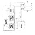
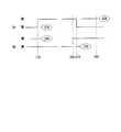
図1〜3は、本発明の第1の実施形態を示し、図1は車両用燃料ガス供給装置のシステム構成図、図2(A〜C)はコントローラにて実行される故障診断の制御フローチャート、図3は故障診断における遮断弁の動作状態を示すタイムチャートである。
【0019】
図1において、車両用燃料ガス供給装置は、燃料電池自動車等の移動体に搭載されるシステムであり、燃料タンク2A、2Bと、燃料タンク2A、2Bよりの燃料ガスと酸化剤ガスの供給を受けて電気化学的な反応により発電を行う燃料電池1と、燃料電池1を安全に効率良く運転すること等を目的とする制御を行うコントローラ7とから構成されている。前記燃料タンク2A、2Bは、水素を燃料ガスとして貯蔵する。容積が等しい二個の燃料タンク2A、2Bは、夫々逆流防止機能付きの遮断弁3A、3Bを介して高圧配管4に接続され、遮断弁3A、3Bおよび高圧配管4を経由して燃料電池1に燃料ガスを供給可能である。
【0020】
高圧配管4には、高圧配管4内の燃料ガスの圧力を計測する圧力センサ5と同じく高圧配管4内の燃料ガスの温度を計測する温度センサ6が配置されている。
【0021】
コントローラ7は、遮断弁制御手段10と、燃料ガス消費量推定手段11、燃料ガス供給量推定手段12、遮断弁状態判定手段13と、から構成されている。
【0022】
遮断弁制御手段10は、遮断弁3A、3Bに対して開閉指令を出力する。
【0023】
燃料ガス消費量推定手段11は、燃料電池1において消費される燃料ガスの量を推定する。
【0024】
燃料ガス供給量推定手段12は、圧力センサ5により計測された燃料ガス圧力と、温度センサ6により計測された燃料ガス温度と、予め測定されている高圧配管4の容積と、遮断弁制御手段10から開指令が出されている燃料タンク2Aまたは2Bの容積とから、燃料ガスの供給量を推定する。
【0025】
遮断弁状態判定手段13は、燃料ガス消費量推定手段11で推定された燃料電池1における燃料消費量と、燃料ガス供給量推定手段12により推定された燃料供給量を比較し、予め定められたロジックに従って、遮断弁3A、3Bの正常状態か故障状態かを判定する。
【0026】
次に、本診断の詳細な手順を、図2のフローチャートに基づいて説明する。フローチャートにおいて、燃料ガス消費量推定手段11の作動はステップ170〜240およびステップ400〜450が、燃料ガス供給量推定手段12の作動はステップ130〜150およびステップ370〜390が、遮断弁状態判定手段13の作動はステップ250〜290、ステップ330〜360およびステップ460〜510が、夫々該当する。また、遮断弁3A、3Bは、閉じたまま故障する場合と開いたまま故障する場合がある。二個の遮断弁3A、3Bおよび燃料タンク2A、2Bを備えるため、燃料電池1に供給される燃料ガスは、いずれの遮断弁3A、3Bも閉じて高圧配管4中の燃料ガスのみからの場合、いずれか一方(他方)の遮断弁3Aまたは3Bが開放し他方(一方)が閉じて一方(他方)の燃料タンク2Aまたは2Bと高圧配管4中の燃料ガスからの場合、両方の遮断弁3A、3Bが開いて両方の燃料タンク2A、2Bと高圧配管4の燃料ガスからの場合がある。
【0027】
先ず、ステップ100で、燃料電池1に対して起動信号が出されたか否かを判断する。起動信号が出されていなければ起動信号が出されるまで待つ。起動信号が出されればステップ110へ進む。
【0028】
ステップ110では、遮断弁制御手段10より遮断弁3Aに対して開指令を出力する。
【0029】
ステップ120では、遮断弁3Aに対して「開」指令が出されてから、予め定められた所定時間経過したか否かを判定する。ここでの所定時間は、予め、遮断弁3Aが開けられてから高圧配管4の圧力が燃料タンク2Aの圧力とほぼ等しくなるまでの時間を計測し、その時間とほぼ等しい値かそれ以上の値に設定する。所定時間の経過後ステップ130へ進む。
【0030】
ステップ130では、高圧配管4での燃料ガス圧を圧力センサ5により計測し、その値をP1とする。
【0031】
ステップ140では、温度センサ6により燃料ガス温度を測定し、その値をT1とする。
【0032】
ステップ150では、遮断弁3Aが正常に開き、遮断弁3Bが閉じている場合において、燃料電池1に消費されて高圧配管4の圧力が△Pだけ低下した時の、推定水素供給量M1を下記の状態方程式を使って、
n1=(P1(V1+Vpipe))/R・T
n2=(P2(V1+Vpipe))/R・T
M1=n1−n2
算出する。ただし、ここで、P2=P1−△P、TはT1を絶対温度で表したもの、Rは気体定数、V1は燃料タンクの容積、Vpipeは高圧配管の容積である。
【0033】
ステップ160では、燃料電池1を実際に起動し、高圧配管4からの燃料の消費が始まる。
【0034】
ステップ170では、推定水素消費量M2の初期値をゼロとする。
【0035】
ステップ190では、図外の電流センサにより燃料電池1の出力電流Iを測定する。
【0036】
ステップ210では、出力電流I、ファラデー定数F、制御周期Ts、および、セル積層数nから、1制御周期の間は燃料電池1の状態に変化はないものと仮定して、下式により、
δM=(I・Ts)・n/(2・F)
1制御周期の間に燃料電池1で消費された水素量δM(mol)を算出する。
【0037】
ステップ220では、ステップ210で算出した水素量δMを推定水素消費量M2に下式にように加算し、
M2=M2+δM
燃料電池1が運転を開始してからの累計の水素消費量M2とする。
【0038】
ステップ230では、高圧配管4での燃料ガス圧を圧力センサ5により再度計測し、その値をP2とする。
【0039】
ステップ240では、燃料ガス圧P1とP2との差を算出し、燃料電池1の燃料消費により高圧配管4の圧力が、予め定められた差圧△Pだけ下がったかを判定する。もし下がっていなければ、ステップ190に戻り、次の制御周期で消費される水素量δMを算出し、推定水素消費量M2を求める。もし、差圧ΔPだけ下がっていればステップ250へ進む。
【0040】
ステップ250では、ステップ150での状態方程式から算出した推定水素供給量Mlと、ステップ220での燃料電池1の出力電流Iから求めた推定水素消費量M2を比較して、その差が所定値△M以下であるかを調べる。所定値△Mは電流センサ、温度センサ6、圧力センサ5の計測誤差などを考慮して、ほぼ同じ値とみなしてかまわない差の値を予め設定しておく。もし、差が所定値ΔM以下であれば、即ち、ほぼ等しい値と判定された場合はステップ300へ進む。もし、差が所定値ΔMよりも大きく、等しい値とはみなせないと判断された場合はステップ260へと進む。
【0041】
ステップ260では、推定水素供給量M1と推定水素消費量M2のどちらが大きいかを判定する。推定水素供給量M1の方が大きければステップ270へ、推定水素消費量M2の方が大きければステップ290へ進む。
【0042】
ステップ270では、推定水素供給量M1の方が大きい、すなわち、遮断弁3Aが正常に動作していた場合の水素消費量M1よりも燃料電池1で実際に消費された水素消費量M2の方が少ないと判定されたのは、遮断弁3Aが開かず、高圧配管4内の水素だけで燃料を供給したため、想定したよりも小さな水素消費で圧力変化△Pが発生したと考え、遮断弁3Aが閉じたまま故障していると判定し、故障フラグをセットするなどの処置を行い、ステップ280の故障処理ルーチンヘと進む。この時の水素消費量は下式の様に、
n1=P1・Vpipe/R・T
n2=P2・Vpipe/R・T
M2=n1+n2
なっているはずである(図3の遮断弁3Aが開かない符号270参照)。
【0043】
ステップ290では、推定水素消費量M2の方が大きい、すなわち、遮断弁3Aが正常に動作していた場合の水素供給量M1よりも燃料電池1で実際に消費された水素消費量M2の方が多いと判定されたのは、遮断弁3Bが開いたままで、高圧配管4内の水素と二つの燃料タンク2A、2Bで燃料ガスを供給したため、想定したよりも大きな水素消費で圧力変化△Pが発生したと考え、遮断弁3Bが開いたまま故障していると判定し、故障フラグをセットするなどの処置を行い、ステップ280の故障処理ルーチンヘと進む。この時の水素供給量は下式の様に、
n1=(P1(V1+V1+Vpipe))/R・T
n2=(P2(V1+V1+Vpipe))/R・T
M2=n1+n2
なっているはずである(図3の遮断弁3Bが閉じない符号290参照)。
【0044】
ステップ300では、遮断弁3Aは、指令値どおりに開いたか、最初から開いたまま、あるいは、遮断弁3A、3Bのいずれか一方が開いていることがわかったので、診断の次の段階ヘと進むために、まず、遮断弁3Bに開指令を出す。
【0045】
ステップ310では、引き続き、遮断弁3Aに閉指令を出す。
【0046】
ステップ320では、ステップ120同様、遮断弁3Aに対して「閉」指令が出されてから、予め定められた所定経過したかを判定する。所定時間が経過したらステップ330へ進む。
【0047】
ステップ330では、高圧配管4での燃料ガス圧を圧力センサ5により計測し、その値をP3とする。この燃料ガス圧P3は、遮断弁3Bが開放することで新たな燃料タンク2Bが高圧配管4に連通し、遮断弁3Aが閉じることで燃料電池1で消費されて低下した燃料ガス圧P2を保っていた今までの燃料タンク2Aが遮断される。このため、燃料ガス圧P3>P2のはずである。
【0048】
ステップ340では、P3とP2との差が△Pとほぼ等しいか否かを判定する。高圧配管4に対して燃料タンク2Bの容積は充分大きいため、遮断弁3A、3Bが正常に作動していれば、燃料ガス圧P3=P2+ΔPとなるはずである。
【0049】
ステップ350では△Pと等しくないということは遮断弁3Bが開かなかったか、遮断弁3A、3Bのどちらか一方が開いたままの故障で、他方が閉じたままの故障と判断し、故障フラグをセットするなどの処置を行い、ステップ360の故障処理ルーチンヘと進む(図3の遮断弁3Bが閉じたままの符号350参照)。
【0050】
ステップ370では、高圧配管4での燃料ガス圧を圧力センサ5により再度計測し、その値をP3とし、温度センサ6により燃料ガス温度を測定し、その値をT1とする。
【0051】
ステップ390では、遮断弁3Aが正常に閉じ、遮断弁3Bが開いている場合の高圧配管4の圧力が△P低下した時の、燃料ガス供給量判定手段12による推定水素供給量M3を下記の状態方程式
n3=(P3(V1+Vpipe))/R・T
n4=(P4(V1+Vpipe))/R・T
M3=n3−n4
を使って算出する。ただし、ここで、P4=P3−△P、TはT1を絶対温度であらわしたもの、Rは気体定数、V1は燃料タンクの容積、Vpipeは高圧配管4の容積である。
【0052】
ステップ400では、推定水素消費量M4の初期値をゼロとする。
【0053】
ステップ410では、図外の電流センサにより燃料電池1の出力電流Iを測定する。
【0054】
ステップ420では、出力電流I、ファラデー定数F、制御周期Ts、および、積層数nから、1制御周期の間は燃料電池1の状態に変化はないものと仮定して、下式により、1制御周期の間に燃料電池1で消費された水素量δM(mol)
δM=I・T・n/2・F
を算出する。
【0055】
ステップ430では、ステップ420で算出した水素量δMを推定水素消費量M4に加算し、
M4=M4+δM
燃料電池1が計測を開始(ステップ400)してからの水素消費量M4とする。
【0056】
ステップ440では、の高圧配管4での燃料ガス圧を圧力センサ5により再度計測し、その値をP4とする。
【0057】
ステップ450では、燃料ガス圧P3とP4との差を算出し、燃料電池1の燃料消費により高圧配管4の圧力が、予め定められた差圧△Pだけ下がったかを判定する。もし下がっていなければ、ステップ410に戻り、次の制御周期で消費される水素量δMを算出し、推定水素消費量M4を求める。もし、下がっていればステップ460へ進む。
【0058】
ステップ460では、ステップ390の状態方程式から算出した推定水素供給量M3と、ステップ430の燃料電池1の出力電流Iから求めた推定水素消費量M4を比較して、その差が所定値△M以下であるかを調べる。△Mは電流センサ、温度センサ6、圧力センサ5の計測誤差などを考慮して、ほぼ同じ値とみなしてかまわない差の値を予め設定しておく。
【0059】
もし、差が所定値ΔM以下であれば、すなわち、ほぼ等しい値と判定された場合はステップ510へ進む。もし、差が所定値ΔMよりも大きく、等しい値とはみなせないと判断された場合はステップ480へと進む。
【0060】
ステップ480では、遮断弁3A、3Bが正常に動作していた場合の水素供給量M3よりも燃料電池1で実際に消費された水素量M4の方が多いと判定されたのは、遮断弁3Aが開いたままで、高圧配管4内の水素と二つの燃料タンク2A、2Bで燃料を供給したため、想定したよりも大きな水素消費で圧力変化△Pが発生したと考え、遮断弁3Aが開いたまま故障していると判定し、故障フラグをセットするなどの処置を行い、ステップ500の故障処理ルーチンヘと進む。この時の水素消費量M4は下式
n3=(P1(V1+V1+Vpipe))/R・T
n4=(P2(V1+V1+Vpipe))/R・T
M4=n3−n4
の様になっているはずである(図3の遮断弁3Aが開いたままの符号480参照)。
【0061】
ステップ510では、遮断弁3Bは、指令どおりに開き、遮断弁3Aは指令通りに閉じたことがわかったので、遮断弁3A、3B共に正常に作動していると判定する。
【0062】
ステップ520では、本診断処理から抜ける。
【0063】
なお、差圧△Pは、圧力センサ5では十分に識別可能である範囲で小さな値としたほうが、診断にかかる時間が少なくなり、より効果的である。
【0064】
また、前記実施態様の説明では、ステップ300〜330で高圧配管4の圧力を測定し、圧力P3とP2との差異がΔPに近いか否かで、ステップ350により遮断弁3Bの閉じたままの故障を判定しているが、これに代えて、図示しないが、ステップ460とステップ480との間に、ステップ260と同様の判定を行うステップを挿入して、遮断弁3A、3Bの故障状態の判定を行ってもよい。
【0065】
また、上記説明の燃料ガス消費量推定手段11は、圧力がΔPだけ低下する間に燃料電池1本体で消費される燃料ガスの量を、燃料電池1の運転状態即ち燃料電池1の出力電流Iを検出することで推定するものであったが、燃料電池1本体へ供給されるの燃料量を検出する燃料供給量検出手段若しくは燃料流量検出手段20を、図1に示すように、燃料電池1の燃料入口に設け、圧力がΔPだけ低下する間に通過する燃料流量を直接検出してもよい。このようにすると、通過流量が直接得られるので、より一層遮断弁3A、3Bの故障判定の精度を向上させることができる。
【0066】
本実施形態においては、以下に記載する効果を奏することができる。即ち、燃料電池1本体で消費される燃料ガスの量を推定する燃料ガス消費量推定手段11と燃料ガス圧力変化量と燃料ガス温度とガス供給経路4容積と開指令が出されている燃料供給源としての燃料タンク2Aまたは2Bの容積から燃料供給源から供給された燃料ガスの量を推定する燃料ガス供給量推定手段12との燃料ガス量推定値を比較して、遮断弁3A、3Bが正常であるか故障しているかを判定するため、遮断弁3A、3Bの開閉状態を精度よく検出でき、遮断弁制御手段10の指令に対比することでより確実な遮断弁3A、3Bの故障状態の診断が可能となる。
【0067】
燃料ガス供給量推定手段12は、遮断弁3A、3B下流にあって燃料ガス圧力変化量と燃料ガス温度とガス供給経路4容積と開指令が出されている燃料タンク2Aまたは2Bの容積から燃料タンク2Aまたは2Bから供給された燃料ガスの量を推定するため、燃料タンク2A、2Bが複数配置されるものであっても、センサ等を追加することなく、それぞれの遮断弁3A、3Bの診断を確実に行うことが可能となる。
【0068】
燃料ガス消費量推定手段11を、燃料電池1の運転状態を検出する燃料電池運転状態検出手段を有し、その検出結果に基づき燃料ガス消費量を推定するよう構成したため、燃料電池1の状態を検出するセンサを有していれば、本診断を適用することができる。
【0069】
燃料電池運転状態検出手段を燃料電池1の出力電流Iを検出する燃料電池出力電流検出手段としたため、燃料電池1に付随している電流計により容易に本発明を適用することができる。
【0070】
(第2実施形態)
本発明における車両用燃料ガス供給装置を実現する実施の形態を、請求項1、3〜5に対応する第2の実施の形態に基づいて説明する。
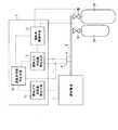
図4、5は、第2の実施の形態の車両用燃料ガス供給装置を示し、図4は燃料電池1の燃料ガス供給装置のシステム構成図、図5(A〜D)はコントローラ7にて実行される故障診断の制御フローチャートを示す。この実施形態の先の実施形態との違いは、燃料タンク2A、2Bの容積が異なったものを用いている点にある。
【0071】
図4において、燃料タンク2Aは容積がV1であり、燃料タンク2Bは2Aよりも大きな容積V2を持つ。
【0072】
以下、図5のフローチャートに基づいてコントローラ7にて実行される故障診断の詳細を説明する。フローチャートにおいて、燃料ガス消費量推定手段11の作動はステップ1200〜1250およびステップ1370〜1420が、燃料ガス供給量推定手段12はステップ1130〜1180が、遮断弁状態判定手段13の作動はステップ1260、1280〜1330およびステップ1430〜1450、1470〜1520が、夫々該当する。
【0073】
ステップ1100では、燃料電池1に対して起動信号が出されたか否かを判断する。起動信号が出されていなければ起動信号が来るまで待つ。起動信号が出されればステップ1110へ進む。
【0074】
ステップ1110では、遮断弁制御手段10より遮断弁3A、3Bに対して開指令を出力する。
【0075】
ステップ1120では、遮断弁3A、3Bに対して「開」指令が出されてから、予め定められた所定経過したか否かを判定する。所定時間が経過したらステップ1130へ進む。
【0076】
ステップ1130では、高圧配管4での燃料ガス圧を圧力センサ5により計測し、その値をPlとする。
【0077】
ステップ1140では、温度センサ6により燃料ガス温度を測定し、その値をT1とする。
【0078】
ステップ1150では、遮断弁3Aが閉じ、遮断弁3Bも閉じている場合の高圧配管4の圧力が、燃料電池1に供給されて△P低下した時の、推定水素供給量Mlを下記の
n1=(P1・Vpipe)/R・T
n2=(P2・Vpipe)/R・T
M1=n1−n2
状態方程式を使って算出する。ただし、ここで、P2=P1−△P、TはT1を絶対温度であらわしたもの、Rは気体定数、Vpipeは高圧配管の容積である。
【0079】
ステップ1160では、遮断弁3Aが開き、遮断弁3Bが閉じている場合の高圧配管4の圧力が、燃料電池1に供給されて△P低下した時の、推定水素供給量M2を下記の
n1=(P1(V1+Vpipe)/R・T
n2=(P2(V1+Vpipe)/R・T
M2=n1−n2
状態方程式を使って算出する。ただし、ここで、V1は燃料タンク3Aの容積である。
【0080】
ステップ1170では、遮断弁3Aが閉じ、遮断弁3Bが開いている場合の高圧配管4の圧力が、燃料電池1に供給されて△P低下した時の、推定水素供給量M3を下記の
n1=(P1(V2+Vpipe)/R・T
n2=(P2(V2+Vpipe)/R・T
M3=n1−n2
状態方程式を使って算出する。ただし、ここで、V2は燃料タンク3Bの容積である。
【0081】
ステップ1180では、遮断弁3Aが開き、遮断弁3Bも開いている場合の高圧配管4の圧力が、燃料電池1に供給されて△P低下した時の、推定水素供給量M4を下記の
n1=(P1(V1+V2+Vpipe))/R・T
n2=(P2(V1+V2+Vpipe))/R・T
M4=n1−n2
状態方程式を使って算出する。
【0082】
ステップ1190では、燃料電池1を実際に起動し、高圧配管4からの燃料の消費が始まる。
【0083】
ステップ1200では、推定水素消費量M5の初期値をゼロとする。
【0084】
ステップ1210では、図外の電流センサにより燃料電池1の出力電流Iを測定する。
【0085】
ステップ1220では、出力電流1、ファラデー定数F、制御周期Tsから、1制御周期の間は燃料電池1の状態に変化はないものと仮定して、下式により、
δM=IT/2・F
1制御周期の間に燃料電池1で消費された水素量δM(mol)を算出する。
【0086】
ステップ1230では、ステップ1220で算出した水素量δMを推定水素消費量M5を下式のように加算し、
M5=M5+δM
燃料電池1が計測(この場合には運転)を開始してからの水素消費量M5とする。
【0087】
ステップ1240では、高圧配管での燃料ガス圧を圧力センサ5により再度計測し、その値をP5とする。
【0088】
ステップ1250では、燃料ガス圧P1とP5との差を算出し、燃料電池1の燃料消費により高圧配管4の圧力が、予め定められた差圧△Pだけ下がったか否かを判定する。もし下がっていなければ、ステップ1210に戻り、次の制御周期で消費される水素量δMを算出し、推定水素消費量M5を再度求める。もし、差圧ΔPだけ下がっていればステップ1260へ進む。
【0089】
ステップ1260では、ステップ1230での推定水素消費量M5とステップ1180での推定水素供給量M4が等しいか否かを判断する。ほぼ等しいと判断されればステップ1270へと進み、等しくないと判断されればステップ1280へと進む。
【0090】
ステップ1270では、燃料電池1で消費された推定水素消費量M5が、遮断弁3A、3B共に指令通りに開いて燃料タンク2A、2Bの両方から燃料ガスが供給されたと判断し、フラグのセット、リセットなどの処理を行い、ステップ1340へと進む。
【0091】
ステップ1280では、推定水素消費量M5とステップ1170での推定水素供給量M3が等しいか否かを判断する。ほぼ等しいと判断されればステップ1290へと進み、等しくないと判断されればステップ1300へと進む。
【0092】
ステップ1290では、燃料電池1で消費された推定水素消費量M5が、遮断弁3Aは指令通りには開かず、3Bは指令通りに開き、燃料タンク2Bのみから燃料が供給されたと判断し、遮断弁3Aが閉じたままの故障であるとし、フラグのセット、リセットなどの処理を行い、ステップ1330の故障処理ルーチンヘと進む。
【0093】
ステップ1300では、推定水素消費量M5とステップ1160の推定水素供給量M2が等しいか否かを判断する。ほぼ等しいと判断されればステップ1310へと進み、等しくないと判断されればステップ1320へと進む。
【0094】
ステップ1310では、燃料電池1で消費された水素消費量M5が、遮断弁3Aは指令通りに開き、遮断弁3Bは指令通りには開かず、燃料タンク2Aのみから燃料が供給されたと判断し、遮断弁3Bが閉じたままの故障であるとし、フラグのセット、リセットなどの処理を行い、ステップ1330の故障処理ルーチンヘと進む。
【0095】
ステップ1320では、燃料電池1で消費された水素消費量M5が、遮断弁3Aは指令通りには開かず、3Bも指令通りには開かず、燃料タンク2A,2Bからは燃料が供給されず、前回の走行で高圧配管4に残った燃料ガスのみが供給されたと判断し、遮断弁3A、3Bの両方が閉じたままの故障であるとし、フラグのセット、リセットなどの処理を行い、ステップ1330の故障処理ルーチンヘと進む。
【0096】
ステップ1340では、遮断弁制御手段10より遮断弁3A、3Bに対して閉指令を出力する。
【0097】
ステップ1350では、高圧配管4での燃料ガス圧を圧力センサ5により計測し、その値をP1とする。
【0098】
ステヅプ1360では、温度センサ6により燃料ガス温度T1を測定し、その値をT1とする。
【0099】
ステップ1370では、推定水素消費量M5の初期値をゼロとする。
【0100】
ステップ1380では、図外の電流センサにより燃料電池1の出力電流Iを測定する。
【0101】
ステップ1390では、出力電流I、ファラデー定数F、制御周期Ts、および、積層数nから、1制御周期の間は燃料電池1の状態に変化はないものと仮定して、1制御周期の間に燃料電池1で消費された水素量δM(mol)を算出する。
【0102】
ステップ1400では、ステップ1390で算出した水素量δMを推定水素消費量M5に加算(M5=M5+δM)し、燃料電池1が計測を開始して(ステップ1370)からの水素消費量M5とする。
【0103】
ステップ1410では、高圧配管4での燃料ガス圧を圧力センサ5により再度計測し、その値をP5とする。
【0104】
ステップ1420では、燃料ガス圧PlとP5との差を算出し、燃料電池1の燃料消費により高圧配管4の圧力が、予め定められた差圧△Pだけ下がったか否かを判定する。もし下がっていなければ、ステップ1380に戻り、次の制御周期で消費される水素量δMを算出し、推定水素消費量M5を再度求める。もし、差圧ΔPだけ下がっていればステップ1430へ進む。
【0105】
ステップ1430では、推定水素消費量M5とステップ1150での推定水素供給量M1が等しいか否かを判断する。ほぼ等しいと判断されればステップ1440へと進み、等しくないと判断されればステップ1470へと進む。
【0106】
ステップ1440では、燃料電池1で消費された水素消費量M5が、遮断弁3A、3B共に指令通りに閉じており、燃料タンク2A、2Bのどちらからも燃料が供給されず、高圧配管4の残水素のみで運転されたと判断する。
【0107】
ステップ1450では、遮断弁3A、3B共に正常に開閉できると判断しフラグのセット、リセットなどの処理を行い、ステップ1460へと進み、故障診断処理から抜ける。
【0108】
ステップ1470では、推定水素消費量M5とステップ1160での推定水素供給量M2が等しいか否かを判断する。ほぼ等しいと判断されればステップ1480へと進み、等しくないと判断されればステップ1490へと進む。
【0109】
ステップ1480では、燃料電池1で消費された水素消費量M5が、遮断弁3Aは指令通りに閉じず、3Bは指令通りに閉じ、燃料タンク2Aから燃料ガスが供給されたと判断し、遮断弁3Aが開いたままの故障であるとし、フラグのセット、リセットなどの処理を行い、ステップ1520の故障処理ルーチンヘと進む。
【0110】
ステップ1490では、推定水素消費量M5とステップ1170での推定水素供給量M3が等しいか否かを判断する。ほぼ等しいと判断されればステップ1500へと進み、等しくないと判断されればステップ1510へと進む。
【0111】
ステップ1500では、燃料電池1で消費された水素消費量M5が、遮断弁3Aは指令通りに閉じ、遮断弁3Bは指令通りには閉じず、燃料タンク2Bから燃料ガスが供給されたと判断し、遮断弁3Bが開いたままの故障であるとし、フラグのセット、リセットなどの処理を行い、ステップ1520の故障処理ルーチンヘと進む。
【0112】
ステップ1510では、燃料電池1で消費された水素消費量M5が、遮断弁3Aは指令通りには閉じず、遮断弁3Bも指令通りには閉じず、燃料タンク2A,2Bから燃料が供給されたと判断し、遮断弁3A、3Bの両方が開いたままの故障であるとし、フラグのセット、リセットなどの処理を行い、ステップ1520の故障処理ルーチンヘと進む。
【0113】
なお、上記例では、燃料タンク2A、2Bの容積が異なる場合に、遮断弁3A、3Bの開閉を同時に指令しているが、先の実施例の様に順番に指令を出して判断することも可能である。
【0114】
本実施の形態にあっては、第1の実施の形態における効果に加えて、複数の燃料タンク2A、2Bは、それぞれの容積が異なる燃料タンクから構成したため、複数の遮断弁3A、3Bを備えるも遮断弁3A、3Bの少ない回数の開閉による診断が可能となる。
【0115】
(第3実施形態)
本発明における車両用燃料ガス供給装置を実現する実施の形態を、請求項1、2、4、5に対応する第3の実施の形態に基づいて説明する。
【0116】
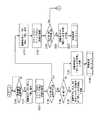
図6は、本発明の第3の実施の形態に係る燃料電池用の燃料ガス供給装置のシステム構成図、図7はコントローラにて実行される故障診断の制御フローチャート、図8は故障診断における遮断弁の動作状態を示すタイムチャートである。この実施形態の先の実施形態との違いは、燃料タンク2A、2Bはそれぞれ3A1、3A2、3Bl、3B2の二つずつの遮断弁を直列に有していることである。この様な形態は、特に車両への適用時等によく用いられる。
【0117】
以下、図7のフローチャートに基づいてコントローラ7にて実行される故障診断の詳細を説明する。フローチャートにおいて、燃料ガス消費量推定手段11と燃料ガス供給量推定手段12との作動はセットにしてステップ2120、2180、2230、2290に含まれており、遮断弁状態判定手段13の作動はステップ2130〜2160、2190〜2210、2240〜2280および2300〜2330が、夫々該当する。
【0118】
ステップ2100では、燃料電池1に対して起動信号が出されたか否かを判断する。起動信号が出されていなければ起動信号が来るまで待つ。起動信号が出されればステップ2110へ進む。
【0119】
ステップ2110では、遮断弁制御手段10より遮断弁3A1、3A2、3B1に対して開指令を出力する。
【0120】
ステップ2120では、図3のステップ120から240までと同様に、所定時間経過後に高圧配管4の燃料ガス圧と温度を測定し、燃料ガス圧がΔPだけ低下する推定水素供給量M1を演算する一方、燃料電池1を起動し推定水素消費量M2の初期値をゼロとし燃料ガス圧の圧力低下がΔPに至るまで、燃料電池1の出力電流Iに対応する制御周期における消費水素量δMを積算して推定水素消費量M2を演算する。
【0121】
ステップ2130では、推定水素供給量Mlと推定水素消費量M2を比較して、その差が所定値△M以下であるか否かを調べる。差が所定値以下であればステップ2170へ進み、所定値より大きければステップ2140へ進む。
【0122】
ステップ2140では、推定水素供給量M1と推定水素消費量M2のどちらが大きいかを判定する。推定水素供給量M1の方が大きければステップ2150へ、推定水素消費量M2の方が大きければステップ2160へ進む。
【0123】
ステップ2150では、推定水素供給量M1の方が大きい、即ち、高圧配管4内の水素だけで燃料を供給する状態であり、遮断弁3A1、3A2のいずれか一方若しくは両方が「閉じたまま故障」と判定し、故障フラグをセットするなどの処置を行い、ステップ2165の故障処理ルーチンヘと進む。この遮断弁開閉状態は、図8において、符号2150にて示される。
【0124】
ステップ2160では、燃料電池1で実際に消費された水素消費量M2の方が多いと判定され、高圧配管4内の水素と二つの燃料タンクで燃料ガスを供給する状態であり、遮断弁3B2が「開いたまま故障」と判定し、故障フラグをセットするなどの処置を行い、ステップ2165の故障処理ルーチンヘと進む。この遮断弁開閉状態は、図8において、符号2160にて示される。
【0125】
ステップ2170では、遮断弁制御手段10により遮断弁3B1に「閉」指令を、遮断弁3B2に「開」指令を夫々出力する。
【0126】
ステップ2180では、図3のステップ120から240までと同様に、所定時間経過後に高圧配管4の燃料ガス圧と温度を測定し、燃料ガス圧がΔPだけ低下する推定水素供給量M1を演算する一方、燃料電池を起動し推定水素消費量M2の初期値をゼロとし燃料ガス圧の圧力低下がΔPに至るまで、燃料電池1の出力電流Iに対応する制御周期における消費水素量δMを積算して推定水素消費量M2を演算する。
【0127】
ステップ2190では、推定水素供給量Mlと推定水素消費量M2を比較して、その差が所定値△M以下であるか否かを調べる。差が所定値以下であればステップ2220へ進み、所定値より大きければステップ2200へ進む。
【0128】
ステップ2200では、燃料電池1で実際に消費された水素消費量M2の方が多いと判定され、高圧配管4内の水素と二つの燃料タンク2A、2Bで燃料ガスを供給する状態であり、遮断弁3B1が「開いたまま故障」と判定し、故障フラグをセットするなどの処置を行い、ステップ2210の故障処理ルーチンヘと進む。この遮断弁開閉状態は、図8において、符号2200で示される。
【0129】
ステップ2220では、遮断弁制御手段10により遮断弁3A2に「閉」指令を、遮断弁3B1に「開」指令を夫々出力する。
【0130】
ステップ2230では、図3のステップ120から240までと同様に、所定時間経過後に高圧配管4の燃料ガス圧と温度を測定し、燃料ガス圧がΔPだけ低下する推定水素供給量M1を演算する一方、燃料電池1を起動し推定水素消費量M2の初期値をゼロとし燃料ガス圧の圧力低下がΔPに至るまで、燃料電池1の出力電流Iに対応する制御周期における消費水素量δMを積算して推定水素消費量M2を演算する。
【0131】
ステップ2240では、推定水素供給量Mlと推定水素消費量M2を比較して、その差が所定値△M以下であるか否かを調べる。差が所定値以下であればステップ2280へ進み、所定値より大きければステップ2250へ進む。
【0132】
ステップ2250では、推定水素供給量M1と推定水素消費量M2のどちらが大きいかを判定する。推定水素供給量M1の方が大きければステップ2260へ、推定水素消費量M2の方が大きければステップ2270へ進む。
【0133】
ステップ2260では、推定水素供給量M1の方が大きい、即ち、高圧配管4内の水素だけで燃料を供給する状態であり、遮断弁3B1、3B2のいずれか一方若しくは両方が「閉じたまま故障」と判定し、故障フラグをセットするなどの処置を行い、ステップ2275の故障処理ルーチンヘと進む。この遮断弁開閉状態は、図8において、符号2260で示される。
【0134】
ステップ2270では、燃料電池1で実際に消費された水素消費量M2の方が多いと判定され、高圧配管4内の水素と二つの燃料タンク2A、2Bで燃料ガスを供給する状態であり、遮断弁3A2が「開いたまま故障」と判定し、故障フラグをセットするなどの処置を行い、ステップ2275の故障処理ルーチンヘと進む。この遮断弁開閉状態は、図8において、符号2270で示される。
【0135】
ステップ2280では、遮断弁制御手段10により遮断弁3A1に「閉」指令を、遮断弁3A2に「開」指令を夫々出力する。
【0136】
ステップ2290では、図3のステップ120から240までと同様に、所定時間経過後に高圧配管4の燃料ガス圧と温度を測定し、燃料ガス圧がΔPだけ低下する推定水素供給量M1を演算する一方、燃料電池1を起動し推定水素消費量M2の初期値をゼロとし燃料ガス圧の圧力低下がΔPに至るまで、燃料電池1の出力電流Iに対応する制御周期における消費水素量δMを積算して推定水素消費量M2を演算する。
【0137】
ステップ2300では、推定水素供給量Mlと推定水素消費量M2を比較して、その差が所定値△M以下であるか否かを調べる。差が所定値以下であればステップ2330へ進み、所定値より大きければステップ2310へ進む。
【0138】
ステップ2310では、燃料電池1で実際に消費された水素消費量M2の方が多いと判定され、高圧配管4内の水素と二つの燃料タンク2A、2Bで燃料ガスを供給する状態であり、遮断弁3A1が「開いたまま故障」と判定し、故障フラグをセットするなどの処置を行い、ステップ2320の故障処理ルーチンヘと進む。この遮断弁開閉状態は、図8において、符号2310で示される。
【0139】
ステップ2330では、遮断弁3A1、3A2、3B1、3B2共に正常に開閉できると判断しフラグのセット、リセットなどの処理を行い、ステップ2340へと進み、故障診断処理から抜ける。
【0140】
本実施の形態にあっては、第1の実施形態における効果に加えて、燃料タンク2A、2B毎に遮断弁3A1、3A2、3B1、3B2を直列に配置しているため、直列となった遮断弁3A1、3A2、または、3B1、3B2が共に「開き放し」で故障する確立が極めて低く、燃料タンク2A、2Bよりの燃料ガスが放出される虞を極めて低くできる。しかも、遮断弁の故障診断を効率的に行える効果を奏する。
【図面の簡単な説明】
【図1】本発明の一実施形態を示す車両用燃料ガス供給装置のシステム構成図。
【図2A】同じくコントローラによる故障診断の最初のフローチャート。
【図2B】同じくコントローラによる故障診断の図2Aに続くフローチャート。
【図2C】同じくコントローラによる故障診断の図2Bに続くフローチャート。
【図3】遮断弁の動作状態を示したタイムチャート。
【図4】本発明の第2の実施形態を示す車両用燃料ガス供給装置のシステム構成図。
【図5A】同じくコントローラによる故障診断の最初のフローチャート。
【図5B】同じくコントローラによる故障診断の図5Aに続くフローチャート。
【図5C】同じくコントローラによる故障診断の図5Bに続くフローチャート。
【図5D】同じくコントローラによる故障診断の図5Cに続くフローチャート。
【図6】本発明の第3の実施形態を示す車両用燃料ガス供給装置のシステム構成図。
【図7A】同じくコントローラによる故障診断の最初のフローチャート。
【図7B】同じくコントローラによる故障診断の図7Aに続くフローチャート。
【図8】遮断弁の動作状態を示したタイムチャート。
【符号の説明】
1 燃料電池
2A、2B 燃料タンク
3A、3B、3A1、3A2、3B1、3B2 遮断弁
4 高圧配管
5 圧力センサ
6 温度センサ
7 コントローラ
10 遮断弁制御手段
11 燃料ガス消費量推定手段
12 燃料ガス供給量推定手段
13 遮断弁状態判定手段[0001]
BACKGROUND OF THE INVENTION
The present invention relates to a vehicular fuel gas supply apparatus suitable for determining a failure state of a shut-off valve disposed at a fuel tank outlet.
[0002]
[Prior art]
Conventionally, it is known that the shut-off valve failure state is determined by opening and closing the shut-off valve to determine the shut-off valve failure state from the downstream gas pressure change. For example, Japanese Patent Laid-Open Nos. 2000-274111 and 2000- No. 303909, Japanese Patent Laid-Open No. 9-22711, and the like.
[0003]
Among the above prior arts, for example, in Japanese Patent Application Laid-Open No. 2000-274111, a shut-off valve and a pressure sensor are arranged in this order in a pipe for supplying gas fuel to a gas engine, and used as a failure diagnosis signal during vehicle stop or operation. Based on the pressure information and the elapsed time taken from the pressure sensor thereafter, the pressure reduction rate is calculated, and the calculated pressure reduction rate is a predetermined pressure reduction rate. When it is smaller than the threshold value, it is determined that the shut-off valve is in a failure state. In this case, it can be determined whether the shut-off valve remains open and cannot be closed, or whether the shut-off valve is locked on the open side and sufficient cut-off performance cannot be obtained.
[0004]
[Problems to be solved by the invention]
By the way, when the conventional technology is applied to a fuel cell vehicle using hydrogen gas as a fuel, the fuel gas flows into the pipe through the shutoff valve, and flows out of the pipe in response to consumption by the fuel cell.
[0005]
However, in the above prior art, since only the pressure change rate of the pipe is measured, the consumption of fuel gas by the fuel cell is not taken into consideration. Therefore, it is difficult to determine whether the cause of the pressure change is based on the failure of the shutoff valve or the consumption of the fuel cell. That is, the failure of the shut-off valve cannot be accurately determined.
[0006]
Accordingly, the present invention has been made in view of the above problems, and an object of the present invention is to provide a vehicle fuel gas supply device that enables more reliable diagnosis of a shut-off valve disposed at the fuel tank outlet.
[0007]
[Means for Solving the Problems]
A first aspect of the present invention is a vehicle fuel gas supply device in which a shutoff valve, a pressure sensor, and a temperature sensor are arranged in a gas supply path for supplying fuel gas from a fuel gas supply source to the fuel cell, and is consumed by the fuel cell. Fuel gas consumption estimation means for estimating the amount of fuel gas, shutoff valve control means for determining the open / close state of the shutoff valve, fuel gas pressure change amount, fuel gas temperature, gas supply path volume, and open command are issued. A fuel gas supply amount estimating means for estimating the amount of fuel gas supplied from the fuel supply source from the volume of the fuel supply source, and a shutoff valve for comparing the fuel gas supply amount estimated value and the fuel gas consumption estimated value And a shut-off valve state determining means for determining whether the valve is normal or malfunctioning. The fuel gas consumption estimation means may measure the amount of fuel gas flowing into the fuel cell with a flow meter or the like, or measure the output current or generated power of the fuel cell to estimate the amount of fuel gas. Also good.
[0008]
According to a second invention, in the first invention, the fuel gas supply source includes a plurality of fuel gas tanks, and the gas supply path is a shut-off valve installed at a supply port of each of the fuel gas tanks; It is characterized by comprising a gas supply pipe that joins the downstream of each shutoff valve and communicates with the fuel cell.
[0009]
According to a third aspect, in the second aspect, the plurality of fuel gas tanks are configured from fuel gas tanks having different volumes.
[0010]
According to a fourth invention, in the first to third inventions, the fuel gas consumption estimation means includes fuel cell operation state detection means for detecting an operation state of the fuel cell, and the fuel gas consumption is based on the detection result. It is characterized by estimating the quantity.
[0011]
According to a fifth invention, in the fourth invention, the fuel cell operating state detecting means is fuel cell output current detecting means for detecting an output current of the fuel cell.
[0012]
【The invention's effect】
Therefore, in the first invention, the fuel gas consumption estimation means for estimating the amount of fuel gas consumed in the fuel cell body, the fuel gas pressure change amount, the fuel gas temperature, the gas supply path volume, and the open command are issued. Whether the shutoff valve is normal or has failed by comparing the estimated value of the fuel gas with the fuel gas supply amount estimation means for estimating the amount of fuel gas supplied from the fuel supply source from the volume of the fuel supply source Therefore, the open / close state of the shut-off valve can be detected with high accuracy, and a more reliable diagnosis of the shut-off valve failure state can be made by comparing with the command of the shut-off valve control means.
[0013]
In the second invention, in addition to the effects of the first invention, the fuel gas supply amount estimation means is downstream of the shutoff valve and outputs a fuel gas pressure change amount, a fuel gas temperature, a gas supply path volume, and an open command. In order to estimate the amount of fuel gas supplied from the fuel supply source from the volume of the fuel supply source, even if a plurality of fuel tanks are arranged, each of the shutoff valves is not added without adding a sensor or the like. Diagnosis can be performed reliably.
[0014]
In the third aspect of the invention, in addition to the effects of the second aspect, the plurality of fuel gas tanks are composed of fuel gas tanks having different volumes. It becomes possible.
[0015]
In the fourth invention, in addition to the effects of the first to third inventions, the fuel gas consumption estimation means has a fuel cell operation state detection means for detecting the operation state of the fuel cell, and based on the detection result. Since the fuel gas consumption is estimated, the diagnosis can be applied if a sensor for detecting the state of the fuel cell is provided.
[0016]
In the fifth aspect of the invention, in addition to the effect of the fourth aspect of the invention, since the fuel cell operating state detecting means is a fuel cell output current detecting means for detecting the output current of the fuel cell, an ammeter attached to the fuel cell is used. The present invention can be easily applied.
[0017]
DETAILED DESCRIPTION OF THE INVENTION
Hereinafter, an embodiment for realizing a vehicular fuel gas supply apparatus according to the present invention will be described based on a first embodiment corresponding to
[0018]
(First embodiment)
1 to 3 show a first embodiment of the present invention, FIG. 1 is a system configuration diagram of a vehicle fuel gas supply device, and FIGS. 2A to 2C are control flowcharts of failure diagnosis executed by a controller. FIG. 3 is a time chart showing the operating state of the shut-off valve in failure diagnosis.
[0019]
In FIG. 1, a vehicular fuel gas supply device is a system mounted on a moving body such as a fuel cell vehicle, and supplies
[0020]
Similar to the
[0021]
The
[0022]
The shut-off valve control means 10 outputs an open / close command to the shut-off
[0023]
The fuel gas consumption amount estimation means 11 estimates the amount of fuel gas consumed in the
[0024]
The fuel gas supply amount estimation means 12 includes a fuel gas pressure measured by the
[0025]
The shut-off valve state determination means 13 compares the fuel consumption amount in the
[0026]
Next, the detailed procedure of this diagnosis is demonstrated based on the flowchart of FIG. In the flowchart, the operation of the fuel gas consumption estimation means 11 is performed in
[0027]
First, in
[0028]
In
[0029]
In
[0030]
In
[0031]
In
[0032]
In
n1 = (P1 (V1 + Vpipe)) / R · T
n2 = (P2 (V1 + Vpipe)) / R · T
M1 = n1-n2
calculate. Here, P2 = P1−ΔP, where T is an absolute temperature of T1, R is a gas constant, V1 is the volume of the fuel tank, and Vpipe is the volume of the high-pressure pipe.
[0033]
In
[0034]
In
[0035]
In
[0036]
In
δM = (I · Ts) · n / (2 · F)
The amount of hydrogen δM (mol) consumed in the
[0037]
In
M2 = M2 + δM
The cumulative hydrogen consumption M2 since the
[0038]
In
[0039]
In
[0040]
In
[0041]
In
[0042]
In
n1 = P1 · Vpipe / R · T
n2 = P2 · Vpipe / R · T
M2 = n1 + n2
(See
[0043]
In
n1 = (P1 (V1 + V1 + Vpipe)) / R · T
n2 = (P2 (V1 + V1 + Vpipe)) / R · T
M2 = n1 + n2
(See
[0044]
In
[0045]
In
[0046]
In
[0047]
In
[0048]
In
[0049]
In
[0050]
In
[0051]
In step 390, the estimated hydrogen supply amount M3 by the fuel gas supply amount determination means 12 when the pressure of the high-
n3 = (P3 (V1 + Vpipe)) / R · T
n4 = (P4 (V1 + Vpipe)) / R · T
M3 = n3-n4
Calculate using. However, here, P4 = P3-ΔP, T is T1 expressed in absolute temperature, R is a gas constant, V1 is the volume of the fuel tank, and Vpipe is the volume of the high-
[0052]
In
[0053]
In
[0054]
In
δM = I · T · n / 2 · F
Is calculated.
[0055]
In step 430, the hydrogen amount δM calculated in
M4 = M4 + δM
The hydrogen consumption M4 after the
[0056]
In
[0057]
In
[0058]
In
[0059]
If the difference is equal to or less than the predetermined value ΔM, that is, if it is determined that the values are substantially equal, the process proceeds to step 510. If it is determined that the difference is greater than the predetermined value ΔM and cannot be regarded as equal, the process proceeds to step 480.
[0060]
In
n3 = (P1 (V1 + V1 + Vpipe)) / R · T
n4 = (P2 (V1 + V1 + Vpipe)) / R · T
M4 = n3-n4
(See
[0061]
In
[0062]
In
[0063]
Note that the differential pressure ΔP is more effective when it is set to a small value within a range that can be sufficiently identified by the
[0064]
In the description of the above embodiment, the pressure of the
[0065]
Further, the fuel gas consumption estimation means 11 described above calculates the amount of fuel gas consumed in the
[0066]
In the present embodiment, the following effects can be achieved. That is, fuel gas consumption estimation means 11 for estimating the amount of fuel gas consumed in the
[0067]
The fuel gas supply amount estimation means 12 is provided with fuel from the fuel gas pressure change amount, the fuel gas temperature, the
[0068]
Since the fuel gas consumption amount estimation means 11 has fuel cell operation state detection means for detecting the operation state of the
[0069]
Since the fuel cell operating state detecting means is the fuel cell output current detecting means for detecting the output current I of the
[0070]
(Second Embodiment)
An embodiment for realizing a vehicular fuel gas supply apparatus according to the present invention will be described based on a second embodiment corresponding to
4 and 5 show the fuel gas supply device for a vehicle according to the second embodiment, FIG. 4 is a system configuration diagram of the fuel gas supply device of the
[0071]
In FIG. 4, the
[0072]
Details of the failure diagnosis executed by the
[0073]
In
[0074]
In
[0075]
In
[0076]
In
[0077]
In step 1140, the fuel gas temperature is measured by the temperature sensor 6, and the value is set to T1.
[0078]
In
n1 = (P1 · Vpipe) / R · T
n2 = (P2 · Vpipe) / R · T
M1 = n1-n2
Calculate using the equation of state. Here, P2 = P1−ΔP, T is T1 expressed in absolute temperature, R is a gas constant, and Vpipe is the volume of the high-pressure pipe.
[0079]
In
n1 = (P1 (V1 + Vpipe) / R · T
n2 = (P2 (V1 + Vpipe) / R · T
M2 = n1-n2
Calculate using the equation of state. Here, V1 is the volume of the
[0080]
In step 1170, the estimated hydrogen supply amount M3 when the pressure in the high-
n1 = (P1 (V2 + Vpipe) / R · T
n2 = (P2 (V2 + Vpipe) / R · T
M3 = n1-n2
Calculate using the equation of state. Here, V2 is the volume of the fuel tank 3B.
[0081]
In step 1180, the estimated hydrogen supply amount M4 when the pressure of the high-
n1 = (P1 (V1 + V2 + Vpipe)) / R · T
n2 = (P2 (V1 + V2 + Vpipe)) / R · T
M4 = n1-n2
Calculate using the equation of state.
[0082]
In
[0083]
In
[0084]
In
[0085]
In
δM = IT / 2 · F
The amount of hydrogen δM (mol) consumed in the
[0086]
In
M5 = M5 + δM
The hydrogen consumption M5 after the
[0087]
In
[0088]
In
[0089]
In
[0090]
In
[0091]
In
[0092]
In
[0093]
In
[0094]
In
[0095]
In
[0096]
In
[0097]
In step 1350, the fuel gas pressure in the high-
[0098]
In step 1360, the fuel gas temperature T1 is measured by the temperature sensor 6, and the value is set to T1.
[0099]
In
[0100]
In
[0101]
In
[0102]
In
[0103]
In
[0104]
In
[0105]
In
[0106]
In
[0107]
In
[0108]
In
[0109]
In
[0110]
In
[0111]
In
[0112]
In
[0113]
In the above example, when the volumes of the
[0114]
In the present embodiment, in addition to the effects of the first embodiment, the plurality of
[0115]
(Third embodiment)
An embodiment for realizing a vehicle fuel gas supply device according to the present invention will be described based on a third embodiment corresponding to
[0116]
FIG. 6 is a system configuration diagram of a fuel gas supply device for a fuel cell according to a third embodiment of the present invention, FIG. 7 is a control flowchart of failure diagnosis executed by the controller, and FIG. It is a time chart which shows the operation state of a valve. The difference of this embodiment from the previous embodiment is that the
[0117]
Details of the failure diagnosis executed by the
[0118]
In
[0119]
In
[0120]
In
[0121]
In
[0122]
In
[0123]
In
[0124]
In
[0125]
In
[0126]
In
[0127]
In
[0128]
In
[0129]
In
[0130]
In
[0131]
In
[0132]
In
[0133]
In
[0134]
In
[0135]
In
[0136]
In
[0137]
In
[0138]
In
[0139]
In
[0140]
In the present embodiment, in addition to the effects of the first embodiment, the shutoff valves 3A1, 3A2, 3B1, 3B2 are arranged in series for each of the
[Brief description of the drawings]
FIG. 1 is a system configuration diagram of a vehicle fuel gas supply device showing an embodiment of the present invention.
FIG. 2A is an initial flowchart of failure diagnosis by the controller.
FIG. 2B is a flowchart subsequent to FIG. 2A for failure diagnosis by the controller.
FIG. 2C is a flowchart subsequent to FIG. 2B of failure diagnosis by the controller.
FIG. 3 is a time chart showing an operating state of a shut-off valve.
FIG. 4 is a system configuration diagram of a vehicle fuel gas supply device showing a second embodiment of the present invention.
FIG. 5A is a first flowchart of failure diagnosis by the controller.
FIG. 5B is a flowchart subsequent to FIG. 5A for failure diagnosis by the controller.
FIG. 5C is a flowchart subsequent to FIG. 5B of failure diagnosis by the controller.
FIG. 5D is a flowchart subsequent to FIG. 5C of failure diagnosis by the controller.
FIG. 6 is a system configuration diagram of a vehicle fuel gas supply device showing a third embodiment of the present invention.
FIG. 7A is an initial flowchart of failure diagnosis by the controller.
FIG. 7B is a flowchart subsequent to FIG. 7A for failure diagnosis by the controller.
FIG. 8 is a time chart showing the operating state of the shut-off valve.
[Explanation of symbols]
1 Fuel cell
2A, 2B Fuel tank
3A, 3B, 3A1, 3A2, 3B1, 3B2 shut-off valve
4 High pressure piping
5 Pressure sensor
6 Temperature sensor
7 Controller
10 Shut-off valve control means
11 Fuel gas consumption estimation means
12 Fuel gas supply amount estimation means
13 Shut-off valve state determination means
Claims (5)
Translated fromJapanese燃料電池により消費される燃料ガスの量を推定する燃料ガス消費量推定手段と、
遮断弁の開閉状態を決定する遮断弁制御手段と、
燃料ガス圧力変化量と燃料ガス温度とガス供給経路容積と開指令が出されている燃料供給源の容積から燃料供給源から供給された燃料ガスの量を推定する燃料ガス供給量推定手段と、
前記燃料ガス供給量推定値と前記燃料ガス消費量推定値を比較して、遮断弁が正常であるか故障しているかを判定する遮断弁状態判定手段と、から構成したことを特徴とする車両用燃料ガス供給装置。In a vehicle fuel gas supply device in which a shutoff valve, a pressure sensor, and a temperature sensor are arranged in a gas supply path for supplying fuel gas from a fuel gas supply source to a fuel cell,
Fuel gas consumption estimation means for estimating the amount of fuel gas consumed by the fuel cell;
Shut-off valve control means for determining the open / close state of the shut-off valve;
Fuel gas supply amount estimation means for estimating the amount of fuel gas supplied from the fuel supply source from the fuel gas pressure change amount, the fuel gas temperature, the gas supply path volume, and the volume of the fuel supply source for which an open command is issued;
A vehicle comprising: a cutoff valve state determination unit that compares the estimated fuel gas supply amount with the estimated fuel gas consumption amount to determine whether the cutoff valve is normal or malfunctioning. Fuel gas supply device.
Priority Applications (1)
| Application Number | Priority Date | Filing Date | Title |
|---|---|---|---|
| JP2002111831AJP3783649B2 (en) | 2002-04-15 | 2002-04-15 | Vehicle fuel gas supply device |
Applications Claiming Priority (1)
| Application Number | Priority Date | Filing Date | Title |
|---|---|---|---|
| JP2002111831AJP3783649B2 (en) | 2002-04-15 | 2002-04-15 | Vehicle fuel gas supply device |
Publications (2)
| Publication Number | Publication Date |
|---|---|
| JP2003308865A JP2003308865A (en) | 2003-10-31 |
| JP3783649B2true JP3783649B2 (en) | 2006-06-07 |
Family
ID=29394518
Family Applications (1)
| Application Number | Title | Priority Date | Filing Date |
|---|---|---|---|
| JP2002111831AExpired - LifetimeJP3783649B2 (en) | 2002-04-15 | 2002-04-15 | Vehicle fuel gas supply device |
Country Status (1)
| Country | Link |
|---|---|
| JP (1) | JP3783649B2 (en) |
Cited By (2)
| Publication number | Priority date | Publication date | Assignee | Title |
|---|---|---|---|---|
| WO2024056256A1 (en)* | 2022-09-15 | 2024-03-21 | Robert Bosch Gmbh | Method and system for detecting a malfunction in a fuel cell system |
| WO2024056254A1 (en)* | 2022-09-15 | 2024-03-21 | Robert Bosch Gmbh | Method and system for detecting a malfunction in a fuel cell system |
Families Citing this family (11)
| Publication number | Priority date | Publication date | Assignee | Title |
|---|---|---|---|---|
| EP2042966B1 (en) | 1999-02-17 | 2013-03-27 | Nippon Telegraph and Telephone Corporation | Original data circulation method, system, apparatus, and computer readable medium |
| JP2006108024A (en)* | 2004-10-08 | 2006-04-20 | Toyota Motor Corp | High pressure gas supply device and fuel cell system using the same |
| JP5099285B2 (en)* | 2004-10-13 | 2012-12-19 | トヨタ自動車株式会社 | Fuel supply device |
| JP5070685B2 (en)* | 2005-07-27 | 2012-11-14 | トヨタ自動車株式会社 | Fuel cell system, gas leak detection device and gas leak detection method |
| JP4917796B2 (en)* | 2005-11-28 | 2012-04-18 | 本田技研工業株式会社 | Fuel cell system |
| JP5120590B2 (en) | 2006-08-25 | 2013-01-16 | トヨタ自動車株式会社 | Fuel cell system and injector diagnostic method |
| JP5389485B2 (en)* | 2009-03-17 | 2014-01-15 | 本田技研工業株式会社 | Control method of fuel cell system |
| JP6229634B2 (en) | 2014-10-24 | 2017-11-15 | トヨタ自動車株式会社 | FUEL CELL SYSTEM, VEHICLE, AND METHOD FOR JUDGING FAILURE OF ON / OFF VALVE |
| JP6313352B2 (en) | 2016-03-09 | 2018-04-18 | 本田技研工業株式会社 | Inspection method for fuel cell system and fuel cell system |
| JP6391625B2 (en)* | 2016-06-03 | 2018-09-19 | 本田技研工業株式会社 | FUEL CELL SYSTEM AND FUEL CELL SYSTEM FAILURE JUDGMENT METHOD |
| KR102698999B1 (en)* | 2018-10-15 | 2024-08-26 | 현대자동차주식회사 | Fuel cell hydrogen supply fault diagnosis system and diagnosis method |
- 2002
- 2002-04-15JPJP2002111831Apatent/JP3783649B2/ennot_activeExpired - Lifetime
Cited By (2)
| Publication number | Priority date | Publication date | Assignee | Title |
|---|---|---|---|---|
| WO2024056256A1 (en)* | 2022-09-15 | 2024-03-21 | Robert Bosch Gmbh | Method and system for detecting a malfunction in a fuel cell system |
| WO2024056254A1 (en)* | 2022-09-15 | 2024-03-21 | Robert Bosch Gmbh | Method and system for detecting a malfunction in a fuel cell system |
Also Published As
| Publication number | Publication date |
|---|---|
| JP2003308865A (en) | 2003-10-31 |
Similar Documents
| Publication | Publication Date | Title |
|---|---|---|
| US10811709B2 (en) | Method of controlling purge of fuel cell system for vehicle | |
| JP3783649B2 (en) | Vehicle fuel gas supply device | |
| US10209158B2 (en) | Apparatus and method for detecting leakage in hydrogen tank of hydrogen fuel cell vehicle | |
| US20090064764A1 (en) | Anomaly judgment device | |
| KR101679971B1 (en) | Failure diagonistic apparatus and method for air supply system of fuel cell | |
| JP3864875B2 (en) | Failure diagnosis system for supply on / off valve | |
| WO2007018132A1 (en) | Fuel cell system and method for judging fuel gas leakage in fuel cell system | |
| CN101194389A (en) | fuel cell system | |
| JP5816842B2 (en) | Gas leak detection system for fuel cell system | |
| CN103748722A (en) | Method for checking the gas tightness of a fuel cell system | |
| CN107645007B (en) | Fuel cell system and vehicle | |
| US9147893B2 (en) | Failure diagnostic device for discharge valve | |
| JP4033376B2 (en) | Fuel supply device | |
| JP2006278088A (en) | Fuel cell system and hydrogen leak detection method | |
| CN105591137A (en) | Fuel cell system | |
| CN108598523B (en) | Fuel cell system and determination method | |
| CN111463454B (en) | High-pressure container system and fuel cell vehicle | |
| JP2005347185A (en) | Fuel cell system and abnormality determination method thereof | |
| JP7668897B2 (en) | How to Calibrate a Fuel Sensor | |
| JP7243140B2 (en) | Hydrogen fuel storage system | |
| JP2004259670A (en) | Fuel cell system | |
| KR20160120556A (en) | Pressure sensor failure diagnosis method of a fuel cell system | |
| JP5110415B2 (en) | Fuel cell system and gas leak detection method | |
| CN101809794B (en) | fuel cell system | |
| CN100468851C (en) | Fault diagnosis device for exhaust valve |
Legal Events
| Date | Code | Title | Description |
|---|---|---|---|
| A977 | Report on retrieval | Free format text:JAPANESE INTERMEDIATE CODE: A971007 Effective date:20050322 | |
| TRDD | Decision of grant or rejection written | ||
| A01 | Written decision to grant a patent or to grant a registration (utility model) | Free format text:JAPANESE INTERMEDIATE CODE: A01 Effective date:20060221 | |
| A61 | First payment of annual fees (during grant procedure) | Free format text:JAPANESE INTERMEDIATE CODE: A61 Effective date:20060306 | |
| R150 | Certificate of patent or registration of utility model | Free format text:JAPANESE INTERMEDIATE CODE: R150 | |
| FPAY | Renewal fee payment (event date is renewal date of database) | Free format text:PAYMENT UNTIL: 20100324 Year of fee payment:4 | |
| FPAY | Renewal fee payment (event date is renewal date of database) | Free format text:PAYMENT UNTIL: 20100324 Year of fee payment:4 | |
| FPAY | Renewal fee payment (event date is renewal date of database) | Free format text:PAYMENT UNTIL: 20110324 Year of fee payment:5 | |
| FPAY | Renewal fee payment (event date is renewal date of database) | Free format text:PAYMENT UNTIL: 20110324 Year of fee payment:5 | |
| FPAY | Renewal fee payment (event date is renewal date of database) | Free format text:PAYMENT UNTIL: 20120324 Year of fee payment:6 | |
| FPAY | Renewal fee payment (event date is renewal date of database) | Free format text:PAYMENT UNTIL: 20130324 Year of fee payment:7 |