JP3782318B2 - Optical switching device and optical switching method - Google Patents
Optical switching device and optical switching methodDownload PDFInfo
- Publication number
- JP3782318B2 JP3782318B2JP2001162149AJP2001162149AJP3782318B2JP 3782318 B2JP3782318 B2JP 3782318B2JP 2001162149 AJP2001162149 AJP 2001162149AJP 2001162149 AJP2001162149 AJP 2001162149AJP 3782318 B2JP3782318 B2JP 3782318B2
- Authority
- JP
- Japan
- Prior art keywords
- mirror
- array
- optical
- light beam
- fiber
- Prior art date
- Legal status (The legal status is an assumption and is not a legal conclusion. Google has not performed a legal analysis and makes no representation as to the accuracy of the status listed.)
- Expired - Fee Related
Links
Images


Landscapes
- Mechanical Light Control Or Optical Switches (AREA)
Description
Translated fromJapanese【0001】
【発明の属する技術分野】
本発明はミラーアレイを利用した光スイッチング技術に関し、光スイッチングを利用する通信、計測、ディスプレイ、スキャナ等の分野に適用して有用なものである。
【0002】
【従来の技術】
ミラーアレイを利用したこの種の光スイッチング技術を、図8〜図11を参照して説明する。
【0003】
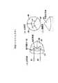
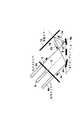
従来の光スイッチング装置は、図8(斜視図)に示すように、ファイバアレイ1、ミラーアレイ6及び平板ミラー13を有するものである。ファイバアレイ1、ミラーアレイ6及び平板ミラー13は、ファイバアレイ1から出射したコリメート光ビーム2がミラーアレイ6で反射され(光ビーム2a参照)、更に平板ミラー13で反射された後(光ビーム2b参照)、再びミラーアレイ6で反射されてファイバアレイ1に入射するように(光ビーム2c参照)、互いに向き合って配置されている。通常の配置は、図9(側面図)に示すように、ファイバアレイ1の光軸(ファイバアレイ光軸)3とミラーアレイ6のミラー法線7とのなす角度が45°となるように、且つ、平板ミラー13のミラー法線14とミラーアレイ6のミラー法線7とのなす角度も45°となるように、光軸調整(アライメント)される。
【0004】
ファイバアレイ1は複数の光ファイバ4を有し、ミラーアレイ6は複数のミラー8を有している。個々のミラー8は、それぞれに対応するミラー支持機構10により、互いに直交する2軸回りに独立に回転可能に支持される。5はファイバアレイ取付板、9はミラーアレイ基板である。
【0005】
光スイッチング方法としては、図9に示すように、ファイバアレイ1を構成する個々の光ファイバ4のうち或る1の光ファイバ(入力ファイバ)4aから出射したコリメート光ビーム2をミラーアレイ6を構成する個々のミラー8のうち或る1のミラー8aで反射させ(光ビーム2a参照)、更に平板ミラー13で反射させた後(光ビーム2b参照)、再び別のミラー8bにて反射させて(光ビーム2c参照)、別の光ファイバ(出力ファイバ)4bに入射させている。
【0006】
このように1つのミラーアレイ6上に存在する別々の2つのミラー8a、8bをスイッチングに用いることにより、システムをできるだけ小型化することができる。また、個々のミラー8はミラー支持機構10により、互いに直交する2軸回りに独立に回転するようにしてあるために、或る程度の回転角度以下の範囲で、ミラーアレイ6から平板ミラー13に任意の角度で光ビームを入射させることができる。
【0007】
ミラー支持機構10としては、例えば図10(a)に示すようなものが使用される。図10(a)に示すミラー支持機構10は、X軸方向の一対のトーションスプリング11aとY軸方向の一対のトーションスプリング11bにより構成されており、個々のミラー8はトーションスプリング11aによりX軸回りに回転可能に支持され、トーションスプリング11bによりY軸回りに回転可能に支持される。
【0008】
ミラー回転駆動には、図10(b)(c)に示すように、4分割電極12を個々のミラー8に対応してに設けた電極アレイ基板12aが用いられる。具体的には、個々のミラー8に下方に個々の4分割電極12を配置し、ミラー8と4分割電極12との間に電位差を与え、静電力を発生させることにより、ミラー回転駆動が行われる。ミラー回転角度の制御は、個々のミラー8と4分割電極12の各々との間に与える4種類の電圧によって行われる。また、ミラー回転角度の最大値は、与えられた電圧の最大値や、個々のミラー8に復元トルクを与えるトーションスプリング11a、11bのばね強さによって左右される。
【0009】
ミラー8aを回転させた場合、このミラー8aで反射して平板ミラー13に向かう光ビーム2aと、平板ミラー13で反射した光ビーム2bとは平行ではない。従って、平板ミラー13で反射した光ビーム2bを出力ファイバ4bへ導くには、2つのミラー8a、8bの回転方向が互いに逆になる(図9参照)。
【0010】
この場合、ファイバアレイ1とミラーアレイ6の個々のミラー8と平板ミラー13のアライメントが上述のように正しい場合は、2つのミラー8a、8bの回転角度は同じである。
【0011】
しかし、アライメントがずれた場合、2つのミラー8a、8bの回転角度が互いに異なる値となる。そのため、こらら2つのミラー8a、8bの回転を独立に制御するか、あるいは、ファイバアレイ1とミラーアレイ6の個々のミラー8と平板ミラー13を厳密にアライメントする必要がある。
【0012】
ファイバアレイ1の光軸3とミラーアレイ6のミラー法線7とがなす角度が45°で、かつ、平板ミラー13のミラー法線14とミラーアレイ6のミラー法線7とがなす角度も45°であるように、正しくアライメントされた場合、ミラーアレイ6のミラー8aを回転させない初期状態では、図11に示すように、入力ファイバ4aから出射した光ビーム2は、平板ミラー13で反射した後、同じ光路を逆にたどって同じ入力ファイバ4aに戻って入射する。
【0013】
従って、光スイッチングが必要でない場合も、入力ファイバ4aから出射した光ビーム2が同じ入力ファイバ4aに戻って入射しないように、いつもミラー8aを回転しておく必要があった。
【0014】
更に、ミラーアレイ6には作製誤差があるため、個々のミラー8が所望の回転角度となるように、個々のミラー8と4分割電極12との間に与える電圧をキャリブレーション(校正)する必要がある。
【0015】
このキャリブレーションに際し、まず、ミラー変形など、個々のミラー8を回転させない初期状態での個々の光ファイバ4とのカップリングを把握する必要がある。
【0016】
しかし、前述のように光ファイバ4a出射した光ビーム2がまた同じ光ファイバ4aに戻るのであるから、初期状態でのカップリングの把握ができないことになり、キャリブレーションを初期状態で行うことは困難であった。このような条件下で個々のミラー8の初期状態を把握するためには、光ファイバ4aに入った戻り光(図11の2c参照)を分岐して取り出す必要があった。
【0017】
【発明が解決しようとする課題】
上述したように、従来の光スイッチング技術では、ミラーアレイ6で反射させた光ビーム2aを平板ミラー13で反射させているので、1つの光ビーム制御に要する2つのミラー8a、8bの回転方向が逆になり、ミラー制御が困難であった。これの解決が本発明の課題である。
【0018】
また、ファイバアレイ1とミラーアレイ6と平板ミラー13との光軸調整がずれていた場合、ミラーアレイ6の2つのミラー8a、8bの回転角度が異なるので、独立にミラー制御するか、光軸調整を厳密に行う必要があった。これの解決が本発明の課題である。
【0019】
更に、光スイッチングが必要ない場合でも、入力ファイバ4aに光ビーム2が戻って入射しないようにミラー8aをいつも回転する必要があった。これの解決が本発明の課題である。
【0020】
更にまた、個々のミラー8が回転しない初期状態では光ビーム2が元の入力ファイバ4aに戻るから、カップリングや、ミラー変形などのミラー初期状態をミラー8aを回転せずに把握することが困難であったため、キャリブレーションにとって最も重要な電圧を印加しないという初期状態の把握が困難であった。このような重大な問題の解決が本発明の課題である。
【0021】
【課題を解決するための手段】
請求項1に係る発明は光スイッチング装置であり、複数の光ファイバを有するファイバアレイと、独立して回転可能に支持された複数のミラーを有するミラーアレイと、入射した光ビームに対して、平行にずれた逆向きの方向へ光ビームを出射する反射光学系を具備する光スイッチング装置において、前記ミラーアレイのミラーを回転駆動しない初期状態にあるとき、前記ファイバアレイの1つ以上の光ファイバ各々に対して、前記光ファイバの任意の1つから出射した光ビームを、前記ミラーアレイの、前記光ファイバの任意の1つに対応する所定のミラーで反射して前記反射光学系に入射すると共に、前記反射光学系で反射された光ビームを前記所定のミラーとは異なる他のミラーで反射して、前記光ファイバの任意の1つとは異なる他の光ファイバに入射するように、前記ファイバアレイ、前記ミラーアレイ及び前記反射光学系の位置を設定し、前記反射光学系はコーナーキューブプリズムまたは中空リトロリフレクターであることを特徴とする。
【0022】
請求項2に係る発明は請求項1に係る発明の光スイッチング装置において、前記ミラーアレイのミラーを回転駆動しない初期状態にあるとき、前記他の光ファイバに入射される光ビーム強度が大きくなるように、前記ミラーアレイのミラーの初期位置を設定したことを特徴とする。
【0023】
請求項3に係る発明は請求項1または2に係る発明の光スイッチング装置において、前記ミラーアレイのミラーを回転駆動するとき、前記所定のミラーと、前記所定のミラー及び前記他のミラーとは異なる更に他のミラーとを、同じ回転方向に、実質的に同じ回転角度で駆動して、前記光ファイバの任意の1つから出射した光ビームを、前記所定のミラーで反射して前記反射光学系に入射すると共に、前記反射光学系で反射された光ビームを前記更に他のミラーで反射して、前記光ファイバの任意の1つ及び前記他の光ファイバとは異なる更に他の光ファイバに入射するようにしたことを特徴とする。
【0025】
又、請求項4に係る発明は光スイッチング方法であり、複数の光ファイバを有するファイバアレイと、独立して回転可能に支持された複数のミラーを有するミラーアレイと、入射した光ビームに対して、平行にずれた逆向きの方向へ光ビームを出射する反射光学系を具備する光スイッチング装置を用いた光スイッチング方法において、前記ミラーアレイのミラーを回転駆動しない初期状態にあるとき、前記ファイバアレイの1つ以上の光ファイバ各々に対して、前記光ファイバの任意の1つから出射した光ビームを、前記ミラーアレイの、前記光ファイバの任意の1つに対応する所定のミラーで反射して前記反射光学系に入射すると共に、前記反射光学系で反射された光ビームを前記所定のミラーとは異なる他のミラーで反射して、前記光ファイバの任意の1つとは異なる他の光ファイバに入射するように、前記ファイバアレイ、前記ミラーアレイ及び前記反射光学系の位置を設定し、前記反射光学系はコーナーキューブプリズムまたは中空リトロリフレクターであることを特徴とする。
又、請求項5に係る発明は請求項4に係る発明の光スイッチング方法において、前記ミラーアレイのミラーを回転駆動しない初期状態にあるとき、前記他の光ファイバに入射される光ビーム強度が大きくなるように、前記ミラーアレイのミラーの初期位置を設定することを特徴とする。
又、請求項6に係る発明は請求項4または5に係る発明の光スイッチング方法において、前記ミラーアレイのミラーを回転駆動するとき、前記所定のミラーと、前記所定のミラー及び前記他のミラーとは異なる更に他のミラーとを、同じ回転方向に、実質的に同じ回転角度で駆動して、前記光ファイバの任意の1つから出射した光ビームを、前記所定のミラーで反射して前記反射光学系に入射すると共に、前記反射光学系で反射された光ビームを前記更に他のミラーで反射して、前記光ファイバの任意の1つ及び前記他の光ファイバとは異なる更に他の光ファイバに入射することを特徴とする。
【0026】
【発明の実施の形態】
以下、図面を参照して、本発明の実施の形態を説明する。図1はコーナキューブプリズムを示し、図2は中空リトロリフレクターを示し、図3はコーナキューブプリズム(または、中空リトロリフレクター)を用いた構成において、ミラーが回転しない場合の光線軌跡を示し、図4はコーナキューブプリズムを用いた光スイッチング装置の構成例を示し、図5は図4に示す装置を側面から見た構成を示し、図6は中空リトロリフレクターを用いた光スイッチング装置の構成例を示し、図7は図6に示す装置を側面から見た構成を示す。
【0027】
[発明の原理」
本発明では、従来の平板ミラー13の代わりに、コーナーキューブプリズムや中空リトロリフレクターを用いて光スイッチングを行う。コーナーキューブプリズムや中空リトロリフレクターは、入射した光ビームに対して平行にずれた逆向きの方向へ光ビームが出射するという特性を持つ反射光学系であり、これらの特性は3枚の平面鏡を互いに直角に配置することにより得られる。
【0028】
図1(a)(b)(c)に示すように、コーナーキューブプリズム15は互いに直交した(互いに90度交わる)3面17、18、19の内部全反射を利用して、入射光線21を180度折り返すプリズムである。入射光線21が入出射面20よりいかなる方向からコーナーキューブプリズム15に入射しても、反射光線22は入射光線21の方向へ必ず、平行且つずれて戻る。コーナーキューブプリズム15は、主に、BK7や合成石英などのガラスで作製される。3つの反射面17〜19には高反射コーティングを施すことが可能である。また、入出射面20には反射防止(AR)コーティングを施すことができる。
【0029】
また、図2(a)(b)(c)に示すように、中空リトロリフレクター23はコーナーキューブプリズム15と同様に互いに直交した(互いに90度交わる)3つの反射面25、26、27により構成されるものであるが、両者の大きな違いは、コーナーキューブプリズム15の光路がガラス内であるのに対し、中空リトロリフレクター23の場合は光路が空気中となることである。このため、中空リトロリフレクター23の場合は、ガラスによる光の吸収の影響を受けず、光の偏光状態への影響や色収差を抑えることができる。中空リトロリフレクター23における入射光線21と出射光線22の関係はコーナーキューブプリズム15と同様であり、入射方向にかかわらず、出射光線22は入射光線21と平行になり、且つ、ずれて戻る。
【0030】
コーナーキューブプリズム15、中空リトロリフレクター23いずれの場合の、入射光線21に対する出射光線22のずれ量とずれ方向は、入射光線21とコーナーキューブプリズム15や中空リトロリフレクター23との相対的な位置関係により定まる。
【0031】
このようなコーナーキューブプリズム15や中空リトロリフレクター23を従来の平板ミラー13の代わりに用いて、図4(コーナーキューブプリズム15使用)や図6(中空リトロリフレクター23使用)に示すようにファイバアレイ1及びミラーアレイ6と組み合わせる。つまり、ファイバアレイ1、ミラーアレイ6及びコーナーキューブプリズム15や中空リトロリフレクター23の位置関係、並びに、ファイバアレイ1中の個々の光ファイバ4の配列ピッチ及びミラーアレイ6中の個々のミラー8の配列ピッチを、ミラーアレイ6を回転駆動しない初期状態でファイバアレイ1中の任意の1の光ファイバ4aから出射される光ビーム2がミラーアレイ6で反射されてコーナーキューブプリズム15や中空リトロリフレクター23に入射し、ここで反射された後、再度ミラーアレイ6で反射され、ファイバアレイ1中の別の光ファイバ(図3の出力ファイバ4c参照)に入射するように設定する。
【0032】
これにより、コーナーキューブプリズム15や中空リトロリフレクター23は入射した光ビーム2aに対して平行且つずれた逆向きの方向へ光ビーム2bを出射するから、1つの光ビーム2のスイッチングのために回転駆動するミラーアレイ6中の2つのミラー8a、8bの回転角度及び回転方向を同一にすることができる。従って、ミラー制御が従来よりも容易になる。
【0033】
また、コーナーキューブプリズム15や中空リトロリフレクター23への入射角が完全に0度でなくても、ミラーアレイ6で反射した光ビーム2aと平行に、コーナーキューブプリズム15や中空リトロリフレクター23から光ビーム2bが戻って来るので、ファイバアレイ1、ミラーアレイ6、コーナーキューブプリズム15(または中空リトロリフレクター23)のアライメント(光軸調整)が従来よりも容易である。
【0034】
更に、図3に示したように、ミラーアレイ6が回転しない初期状態でも、コーナーキューブプリズム15(または中空リトロリフレクター23)で反射した光ビーム2bは、ミラーアレイ6の別なミラー8bに入射し、入力ファイバ4aとは別の出力ファイバ4cに戻る。従って、個々のミラー8の初期状態を容易に把握でき、正確なキャリブレーションが可能になる。また、特別に光スイッチングを必要としない場合には、ミラーアレイ6を回転する必要がない。
【0035】
[第1実施例]
図4、図5を参照して、本発明の1実施例に係る光スイッチング装置及び方法を説明する。
【0036】
本例の光スイッチング装置は、図4に示すように、ファイバアレイ1と、ミラーアレイ6と、コーナーキューブプリズム15を備えるものである。ファイバアレイ1、ミラーアレイ6及びコーナーキューブプリズム15は、ミラーアレイ6を回転駆動しない初期状態でファイバアレイ1中の任意の1の光ファイバ4aから出射される光ビーム2がミラーアレイ6で反射されてコーナーキューブプリズム15に入射し、ここで反射された後、再度ミラーアレイ6で反射され、ファイバアレイ1中の別の光ファイバ(図3の出力ファイバ4c参照)に入射するように、配置されている。
【0037】
そのため、まず、ファイバアレイ1を有するファイバアレイ取付板5と、ミラーアレイ6を有するミラーアレイ基板9と、4分割電極を有する電極アレイ基板(図10の符号12、12a参照)と、コーナーキューブプリズム15を用意しておく。
【0038】
ここで、ファイバアレイ1はファイバアレイ取付板5に設けた複数の光ファイバ4を有している。ミラーアレイ6は図10にて前述したように、個々のミラー8を互いに直交する2軸回りに独立に回転可能に支持する、例えばX軸方向の一対のトーションスプリング11aとY軸方向の一対のトーションスプリング11bにより構成されたミラー支持機構10を有している。個々のミラー8は通常、同一平面上に位置する。電極アレイ基板12aは、個々のミラー8に対応してに設けた4分割電極12を有している。ミラーアレイ6と電極アレイ基板12aは、個々のミラー8に下方に個々の4分割電極12が位置するように予め両者が一体形成されたものでも良く、あるいは、別々に形成したミラーアレイ6と電極アレイ基板12aを個々のミラー8に下方に個々の4分割電極12が位置するように組み合わせたものでも良い。ミラーアレイ6や4分割電極12はこれらが小さいことから、フォトリソグラフィ技術など、マイクロマシン分野の技術を用いて作製することができる。
【0039】
次に、上述したファイバアレイ取付板5とミラーアレイ基板9とコーナーキューブプリズム15との位置関係を、例えば45度に設定する。具体的には、ファイバアレイ光軸(個々の光ファイバ8の光軸)とミラーアレイ6のミラー法線とのなす角度が45°となるように、また、コーナーキューブプリズム15の法線とミラーアレイ6のミラー法線とのなす角度も45°となるように、光軸調整(アライメント)しておく。
【0040】
従来の平板ミラー13を使用した場合と、その代わりにコーナーキューブプリズム15を使用した場合を比較して、実験を行った。実験を行うまでもなく、理論的な洞察からも明らかなことであるが、光ビームのX方向の偏向はミラーアレイ6の個々のミラー8のY軸回りの回転を与えることにより行い、Y方向の光ビーム偏向はミラーアレイ6の個々のミラー8のX軸回りの回転を与えることにより行うことができる。
【0041】
また、電極アレイ基板12aの4分割電極12に電圧を与えないミラーアレイ6が初期状態の場合、図3に示したように、入力ファイバ4aから出射したコリメート光ビーム2は、ミラーアレイ6のミラー8aで反射され(光ビーム2a参照)、コーナーキューブプリズム15に入射後、コーナーキューブプリズム15の中心を挟むように平行に出射され(光ビーム2b参照)、再びミラーアレイ6の別のミラー8bで反射され(光ビーム2c参照)、入力ファイバ4aとは異なる別の光ファイバ(出力ファイバ)4cに入射した。
【0042】
更に、初期キャリブレーション(ミラーアレイ6の初期状態でのキャリブレーション)として、個々のミラー8について、その下部の4分割電極12の各々にバイアスを与え、出力ファイバ4cに戻ってくる光ビーム2cの光強度が高くなるように電圧を調整した。このときの電圧の値を、個々のミラー8に対する初期キャリブレーション値として、メモリに記憶しておいた。
【0043】
従って、ミラーアレイ6の初期状態においては、従来の平板ミラー13を使用した場合は前述したように下記(1)に示す問題点があったが、本例のコーナーキューブプリズム15を用いた場合は下記(2)に示すように、この問題点が解決できた。
(1)平板ミラー13を使用した場合の問題点:図11に示したように、平板ミラー13を用いると、入力ファイバ4aから出射した光ビーム2が、反射後、同じ入力ファイバ4aに戻ってくるため、ミラーアレイ6による反射後の光強度測定が困難であり、この状態でミラー初期状態を把握するには入力ファイバ4aに入った戻り光ビーム2cを分岐して取り出す必要があった。また、入力ファイバ4aから出射した光ビーム2はミラー8aを回転させないことには、同じ光ファイバ4aに戻ることになるから、光スイッチングが必要でない場合にも、ミラー8aを回転させておかなければならなかった。
(2)本例の利点:コーナーキューブプリズム15を用いると、図に示したように、入力ファイバ4aと出力ファイバ4cが必ず異なるため、光ビーム2cを分岐して取り出すことなくミラー反射後の光強度測定を測定でき、ミラー初期状態の把握及びキャリブレーションが容易である。また、入力ファイバ4aと出力ファイバ4cが必ず異なることから、光ビームを特に切り換える必要がない場合には、ミラー8aを回転する必要はない。
【0044】
次に、初期設定(キャリブレーションによっては若干は回転するかもしれないが、基本的にはミラー回転角度がゼロ)から、ミラー8aを回転させて他の光ファイバに光ビームを出力させる場合、ミラー8aの回転をX軸回りにα0度、Y軸回りにβ0度にする。同時に、コーナーキューブプリズム15から出射した光ビーム2bもコーナーキューブプリズム15に入射した光ビーム2aと平行であることから、コーナーキューブプリズム15から出射した光ビーム2bを反射するミラー8bの回転角度も同様に、X軸回りにα0度、Y軸回りにβ0度にすれば良い。つまり、2つのミラー8a、8bの回転角度及び回転方向は同じで良い(図5参照)。
【0045】
これに対して、平板ミラー13を用いた従来では前述したが、ファイバアレイ1の光軸とミラーアレイ6のミラー法線のなす角度が45度で、平板ミラー13の法線とミラーアレイ6のミラー法線のなす角度が45度である場合にのみ、平板ミラー13から出た光ビーム2bは、ミラー8bの回転角度がX軸回りに−α0度、Y軸回りに−β0度で、出力ファイバ4bに入射する。
【0046】
また、平板ミラー13を用いた従来では前述したが、ファイバアレイ1とミラーアレイ6と平板ミラー13のアライメントがそれぞれ45度になっていない場合には、回転駆動する2つのミラー8a、8bの回転角度が異なり、独立にミラー制御するか、アライメントを厳密にとる必要があったが、コーナーキューブプリズム15を用いた場合は、ファイバアレイ1とミラーアレイ6とコーナーキューブプリズム15のアライメントの位置関係がそれぞれ45度になっていない場合でも、回転駆動する2つのミラー8a、8bの回転角度が同じになり、独立にミラー制御する必要がなく、また、アライメントを厳密にとる必要もない。
【0047】
なお、コーナーキューブプリズム15の内部では、通常、3回反射される。ミラー8aからコーナーキューブプリズム15に入射する光ビーム2aは、3つの反射面のうち1つで全反射され(光ビーム16a参照)、更に別の反射面で全反射され(光ビーム16b参照)、更に別の反射面で全反射されて、光ビーム2bとなって出射される。
【0048】
以上より、コーナーキューブプリズム15を使用した光スイッチング装置では、基本的には、ミラーアレイ中6の2つのミラー8a、8bを回転駆動し、ファイバアレイ中の光ファイバ4aが出射する光ビーム2をミラー8aで反射させてコーナーキューブプリズム15に入射し、ここでの反射後、更にミラー8bで反射させ、ファイバアレイ1中の別の光ファイバ4bに入射することことにより、光スイッチングを行うことができる。
【0049】
また、ミラーアレイ6の作製誤差を吸収するために、ミラー制御をキャリブレーションする場合は、図3に示すように、ミラーアレイ6を回転駆動しない初期状態で任意の1の光ファイバ4aが出射する光ビーム2が別の光ファイバ4cに入射して出力される光ビーム2cの強度が大きくなるように、ミラーアレイ6の初期キャリブレーションを行い、その後、初期キャリブレーション値を利用し、図5に示すように、ミラーアレイ6中の2つのミラー8a、8bを回転駆動し、ファイバアレイ中の1の光ファイバ4aが出射する光ビーム2をミラー8bで反射させてコーナーキューブプリズム15に入射し、コーナーキューブプリズム15による反射後、更にミラー8bで反射させ、ファイバアレイ1中の別の光ファイバ4bに入射させて、所望の光スイッチングを行うことができる。
【0050】
いずれの場合も、2つのミラー8a、8bを同じ回転方向で、実質的に同じ回転角度で駆動することができる。
【0051】
[第2実施例]
次に、図6、図7を参照して、本発明の2実施例に係る光スイッチング装置及び方法を説明する。
【0052】
本例の光スイッチング装置は、図6に示すように、第1実施例(図4、図5)のコーナーキューブプリズム15の代わりに中空リトロリフレクター23を用いたものであり、ファイバアレイ1と、ミラーアレイ6と、中空リトロリフレクター23を備えている。従って、ファイバアレイ1、ミラーアレイ6及び中空リトロリフレクター23は、ミラーアレイ6を回転駆動しない初期状態でファイバアレイ1中の任意の1の光ファイバ4aから出射される光ビーム2がミラーアレイ6で反射されて中空リトロリフレクター23に入射し、ここで反射された後、再度ミラーアレイ6で反射され、ファイバアレイ1中の別の光ファイバ(図3の出力ファイバ4c参照)に入射するように、配置されている。
【0053】
そのため、まず、ファイバアレイ1を有するファイバアレイ取付板5と、ミラーアレイ6を有するミラーアレイ基板9と、4分割電極を有する電極アレイ基板(図10の符号12、12a参照)と、中空リトロリフレクター23を用意し、ファイバアレイ取付板5とミラーアレイ基板9と中空リトロリフレクター23との位置関係を、例えば45度に設定する。具体的には、ファイバアレイ光軸(個々の光ファイバ8の光軸)とミラーアレイ6のミラー法線とのなす角度が45°となるように、また、中空リトロリフレクター23の法線とミラーアレイ6のミラー法線とのなす角度も45°となるように、光軸調整(アライメント)しておく。
【0054】
コーナーキューブプリズム15その代わりに中空リトロリフレクター23を使用した場合も光ビームのX方向の偏向はミラーアレイ6の個々のミラー8のY軸回りの回転を与えることにより行い、Y方向の光ビーム偏向はミラーアレイ6の個々のミラー8のX軸回りの回転を与えることにより行うことができる。
【0055】
また、電極アレイ基板12aの4分割電極12に電圧を与えないミラーアレイ6が初期状態の場合、入力ファイバ4aから出射したコリメート光ビーム2は、ミラーアレイ6のミラー8aで反射され(光ビーム2a参照)、中空リトロリフレクター23に入射後、中空リトロリフレクター23の中心を挟むように平行に出射され(光ビーム2b参照)、再びミラーアレイ6の別のミラー8bで反射され(光ビーム2c参照)、入力ファイバ4aとは異なる別の光ファイバ(図3の出力ファイバ4c参照)に入射した。
【0056】
更に、初期キャリブレーション(ミラーアレイ6の初期状態でのキャリブレーション)として、個々のミラー8について、その下部の4分割電極12の各々にバイアスを与え、出力ファイバ4cに戻ってくる光ビーム2cの光強度が高くなるように電圧を調整した。このときの電圧の値を、個々のミラー8に対する初期キャリブレーション値として、メモリに記憶しておいた。
【0057】
従って、中空リトロリフレクター23を用いた場合も、ミラーアレイ6の初期状態においては、入力ファイバ4aと出力ファイバ4bが必ず異なるため、光ビーム2cを分岐して取り出すことなくミラー反射後の光強度測定を測定でき、ミラー初期状態の把握及びキャリブレーションが容易であり、また、入力ファイバ4aと出力ファイバ4cが必ず異なることから、光ビームを特に切り換える必要がない場合には、ミラー8aを回転する必要はないという利点がある。
【0058】
次に、初期設定(キャリブレーションによっては若干は回転するかもしれないが、基本的にはミラー回転角度がゼロ)から、ミラー8aを回転させて他の光ファイバに光ビームを出力させる場合、ミラー8aの回転をX軸回りにα0度、Y軸回りにβ0度にする。同時に、中空リトロリフレクター23から出射した光ビーム2bも中空リトロリフレクター23に入射した光ビーム2aと平行であることから、中空リトロリフレクター23から出射した光ビーム2bを反射するミラー8bの回転角度も同様に、X軸回りにα0度、Y軸回りにβ0度にすれば良い。つまり、2つのミラー8a、8bの回転角度及び回転方向は同じで良い。
【0059】
また、ファイバアレイ1とミラーアレイ6と中空リトロリフレクター23のアライメントの位置関係がそれぞれ45度になっていない場合でも、回転駆動する2つのミラー8a、8bの回転角度が同じになり、独立にミラー制御する必要がなく、また、アライメントを厳密にとる必要もない。
【0060】
中空リトロリフレクター23の内部では、通常、3回反射される。ミラー8aから中空リトロリフレクター23に入射する光ビーム2aは、3つの反射面のうち1つで全反射され(光ビーム24a参照)、更に別の反射面で全反射され(光ビーム24b参照)、更に別の反射面で全反射されて、光ビーム2bとなって出射される。
【0061】
以上より、中空リトロリフレクター23を使用した光スイッチング装置でも、基本的には、ミラーアレイ中6のミラー8aと別のミラー8bを回転駆動し、ファイバアレイ中の光ファイバ4aが出射する光ビーム2をミラー8aで反射させて中空リトロリフレクター23に入射し、ここでの反射後、更にミラー8bで反射させ、ファイバアレイ1中の別の光ファイバ4bに入射することことにより、光スイッチングを行うことができる。
【0062】
また、ミラーアレイ6の作製誤差を吸収するために、ミラー制御をキャリブレーションする場合は、図3に準じて、ミラーアレイ6を回転駆動しない初期状態で任意の1の光ファイバ4aが出射する光ビームが別の光ファイバ4cに入射して出力される光ビーム2cの強度が大きくなるように、ミラーアレイ6の初期キャリブレーションを行い、その後、初期キャリブレーション値を利用し、図7に示すように、ミラーアレイ6中の2つのミラー8a、8bを回転駆動し、ファイバアレイ中の1の光ファイバ4aが出射する光ビーム2をミラー8bで反射させて中空リトロリフレクター23に入射し、中空リトロリフレクター23による反射後、更にミラー8bで反射させ、ファイバアレイ1中の別の光ファイバ4bに入射させて、所望の光スイッチングを行うことができる。
【0063】
また、いずれの場合も、2つのミラー8a、8bを同じ回転方向で、実質的に同じ回転角度で駆動することができる。
【0064】
ここで、前述したように、中空リトロリフレクター23はコーナーキューブプリズム15と同様に互いに直交した(互いに90度交わる)3つの反射面25、26、27により構成されるものであり、入射方向によらず入射する光ビーム2aとと出射する光ビーム2bとは平行にずれる(光入射方向に必ず反射する)が、両者の大きな違いは、コーナーキューブプリズム15の光路がガラス内であるのに対し、中空リトロリフレクター23の場合は光路が空気中となることである。そのため、中空リトロリフレクター23の場合は、ガラスによる光の吸収の影響を受けず、光の偏光状態への影響や色収差を抑えることができる。
【0065】
つまり、中空リトロリフレクター23を用いた場合は、コーナーキューブプリズム15を用いた場合に比べ、色収差や損失が少なく、光の偏波面の回転がなく偏光状態への影響を抑えることができる。
【0066】
特に、波長の異なる光を用いた波長多重通信においては、色収差をできるだけ抑えることが重要であり、中空リトロリフレクター23の使用はこれに適している。また、ガラスのコーナーキューブプリズム15とは異なり、入射面に反射防止コーティングを施す必要がないという利点がある。赤外領域(波長1〜12μm)用には、反射面25〜27として通常は金コートした反射面を用いると良い。
【0067】
コーナーキューブプリズム15、中空リトロリフレクター23いずれを用いる場合も、ファイバアレイ1は入力ファイバアレイと出力ファイバアレイが混在したものでも、別れているものでも良い。
【0068】
【発明の効果】
以上説明したように、本発明に係る光スイッチング装置及び方法においては、従来の平板ミラーに代えて、コーナーキューブプリズムや中空リトロリフレクターなど入射した光ビームに対して平行にずれた逆向きの方向へ光ビームが出射するという特性を持つ反射光学系を使用し、ファイバアレイ(入力光ファイバ、出力光ファイバ)と、ミラーアレイと、入射した光ビームに対して平行にずれた逆向きの方向へ光ビームが出射するという特性を持つ反射光学系との構成で光スイッチングを行うものである。
【0069】
これにより、1つの光ビームのスイッチングのために駆動するミラーアレイ中の2つのミラーの回転角度を同一にすることができ、ミラー回転制御が従来に比べて容易である。
【0070】
また、コーナーキューブプリズムや中空リトロリフレクターへの入射角が完全に0度でなくてもコーナーキューブプリズムや中空リトロリフレクターへ入射した光ビームと平行にコーナーキューブプリズムや中空リトロリフレクターから光ビームが戻ってくるので、ファイバアレイとミラーアレイ、ミラーアレイとコーナーキューブプリズムや中空リトロリフレクターとのアライメント(光軸調整)が従来に比べて容易である。
【0071】
更に、ミラーアレイが回転しない初期状態でも、1の光ファイバ及び1のミラーを経てコーナーキューブプリズムや中空リトロリフレクターで反射した光ビームは別のミラーに入射し、別な光ファイバに戻るため、ミラーの初期状態を容易キャリブレーションすることができる。同様の理由により、光スイッチングが必要ない場合には、ミラーを回転する必要がない。
【図面の簡単な説明】
【図1】コーナキューブプリズムを示す図。
【図2】中空リトロリフレクターを示す図。
【図3】コーナキューブプリズム(または、中空リトロリフレクター)を用いた光スイッチングにおいて、ミラーが回転しない場合の光線軌跡を示す図。
【図4】コーナキューブプリズムを用いた光スイッチング装置の構成例を示す図。
【図5】図4に示す光スイッチング装置を側面から見た構成を示す図。
【図6】中空リトロリフレクターを用いた光スイッチング装置の構成例を示す図。
【図7】図6に示す光スイッチング装置を側面から見た構成を示す図。
【図8】従来の平板ミラーを用いた光スイッチング装置の構成を示す斜視図。
【図9】図8の側面図。
【図10】ミラーアレイの構成を示す。
【図11】従来の平板ミラーを用いた光スイッチングにおいて、ミラーが回転しない場合の光線軌跡を示す図。
【符号の説明】
1 ファイバアレイ
2、2a、2b、2c 光ビーム
3 ファイバアレイ光軸
4、4a、4b、4c 光ファイバ
5 ファイバアレイ取付板
6 ミラーアレイ
7 ミラーアレイのミラー法線
8、8a、8b ミラー
9 ミラーアレイ基板
10 ミラー支持機構
11a、11b トーションスプリング
12 4分割電極
12a 電極アレイ基板
13 平板ミラー(従来)
14 平板ミラーのミラー法線
15 コーナーキューブプリズム
16a、16b コーナーキューブプリズム中の光ビーム
17、18、19 反射面
20 入出射面
21 入射光線
22 出射光線
23 中空リトロリフレクター
24a、24b 中空リトロリフレクター中の光ビーム
25、26、27 反射面[0001]
BACKGROUND OF THE INVENTION
The present invention relates to an optical switching technique using a mirror array, and is useful when applied to the fields of communication, measurement, display, scanner and the like using optical switching.
[0002]
[Prior art]
This type of optical switching technology using a mirror array will be described with reference to FIGS.
[0003]
As shown in FIG. 8 (perspective view), the conventional optical switching device has a fiber array 1, a
[0004]
The fiber array 1 has a plurality of optical fibers 4, and the
[0005]
As an optical switching method, as shown in FIG. 9, a collimated light beam 2 emitted from one optical fiber (input fiber) 4a among the individual optical fibers 4 constituting the fiber array 1 is formed into a
[0006]
Thus, by using two
[0007]
As the
[0008]
As shown in FIGS. 10B and 10C, an
[0009]
When the
[0010]
In this case, when the alignment between the
[0011]
However, when the alignment is shifted, the rotation angles of the two
[0012]
The angle formed by the optical axis 3 of the fiber array 1 and the mirror normal 7 of the
[0013]
Therefore, even when optical switching is not required, it is necessary to always rotate the
[0014]
Further, since there is a manufacturing error in the
[0015]
In this calibration, first, it is necessary to grasp the coupling with the individual optical fibers 4 in the initial state where the
[0016]
However, since the light beam 2 emitted from the
[0017]
[Problems to be solved by the invention]
As described above, in the conventional optical switching technology, since the
[0018]
Further, when the optical axis adjustment of the fiber array 1, the
[0019]
Further, even when optical switching is not required, it is necessary to always rotate the
[0020]
Furthermore, since the light beam 2 returns to the
[0021]
[Means for Solving the Problems]
The invention according to claim 1 is an optical switching device, and is parallel to a fiber array having a plurality of optical fibers, a mirror array having a plurality of mirrors that are independently rotatably supported, and an incident light beam. Each of the one or more optical fibers of the fiber array when in an initial state in which the mirrors of the mirror array are not rotationally driven in an optical switching device comprising a reflective optical system that emits a light beam in a direction opposite to On the other hand, the light beam emitted from any one of the optical fibers is reflected by a predetermined mirror corresponding to any one of the optical fibers of the mirror array and is incident on the reflection optical system. The light beam reflected by the reflection optical system is reflected by another mirror different from the predetermined mirror, and is different from any one of the optical fibers. To be incident on the optical fiber, the fiber array, sets the position of the mirror array and the reflective optical systemThe reflection optical system is a corner cube prism or a hollow retro reflector. It is characterized by that.
[0022]
The invention according to claim 2The invention according to claim 1 In an optical switching device,The initial position of the mirror of the mirror array is set so that the intensity of the light beam incident on the other optical fiber is increased when the mirror of the mirror array is in an initial state where the mirror is not rotationally driven. It is characterized by that.
[0023]
The invention according to claim 3 is the optical switching device according to claim 1 or 2.When rotating the mirrors of the mirror array, the predetermined mirror and another mirror different from the predetermined mirror and the other mirror are rotated in the same rotational direction and at substantially the same rotational angle. The light beam emitted from any one of the optical fibers is reflected by the predetermined mirror and incident on the reflection optical system, and the light beam reflected by the reflection optical system is further reflected by the other one. So that it is incident on any one of the optical fibers and another optical fiber different from the other optical fibers. It is characterized by that.
[0025]
Claims4 The invention according to the present invention is an optical switching method, in which a fiber array having a plurality of optical fibers, a mirror array having a plurality of mirrors that are independently supported to rotate, and an incident light beam are shifted in parallel In an optical switching method using an optical switching device including a reflection optical system that emits a light beam in a reverse direction, when the mirror of the mirror array is in an initial state in which no mirror is driven to rotate, one or more of the fiber array For each optical fiber, a light beam emitted from any one of the optical fibers is reflected by a predetermined mirror of the mirror array corresponding to any one of the optical fibers, and is reflected on the reflection optical system. The light beam that is incident and reflected by the reflection optical system is reflected by another mirror different from the predetermined mirror, and the optical fiber is arbitrarily selected. To be incident on different other optical fiber is one with, the fiber array, sets the position of the mirror array and the reflective optical systemThe reflection optical system is a corner cube prism or a hollow retro reflector. It is characterized by that.
[0026]
DETAILED DESCRIPTION OF THE INVENTION
Embodiments of the present invention will be described below with reference to the drawings. 1 shows a corner cube prism, FIG. 2 shows a hollow retroreflector, and FIG. 3 shows a ray trajectory when the mirror does not rotate in the configuration using the corner cube prism (or hollow retroreflector). Shows a configuration example of an optical switching device using a corner cube prism, FIG. 5 shows a configuration of the device shown in FIG. 4 viewed from the side, and FIG. 6 shows a configuration example of an optical switching device using a hollow retroreflector. 7 shows a configuration of the apparatus shown in FIG. 6 viewed from the side.
[0027]
[Principle of the invention]
In the present invention, light switching is performed using a corner cube prism or a hollow retroreflector instead of the conventional
[0028]
As shown in FIGS. 1A, 1B, and 1C, the
[0029]
2A, 2B, and 2C, the hollow retro-
[0030]
In either case of the
[0031]
Using such a
[0032]
As a result, the
[0033]
Even if the angle of incidence on the
[0034]
Further, as shown in FIG. 3, even in the initial state where the
[0035]
[First embodiment]
An optical switching device and method according to an embodiment of the present invention will be described with reference to FIGS.
[0036]
As shown in FIG. 4, the optical switching device of this example includes a fiber array 1, a
[0037]
Therefore, first, a fiber
[0038]
Here, the fiber array 1 has a plurality of optical fibers 4 provided on the fiber
[0039]
Next, the positional relationship among the above-described fiber
[0040]
An experiment was conducted by comparing the case where the conventional
[0041]
When the
[0042]
Further, as an initial calibration (calibration in the initial state of the mirror array 6), for each
[0043]
Therefore, in the initial state of the
(1) Problems when the
(2) Advantages of this example: When the
[0044]
Next, when the
[0045]
On the other hand, as described above in the prior art using the
[0046]
Further, as described above in the prior art using the
[0047]
In the
[0048]
As described above, in the optical switching device using the
[0049]
Further, when the mirror control is calibrated in order to absorb the manufacturing error of the
[0050]
In either case, the two
[0051]
[Second Embodiment]
Next, an optical switching device and method according to two embodiments of the present invention will be described with reference to FIGS.
[0052]
As shown in FIG. 6, the optical switching device of this example uses a
[0053]
Therefore, first, a fiber
[0054]
Even when a
[0055]
When the
[0056]
Further, as an initial calibration (calibration in the initial state of the mirror array 6), for each
[0057]
Accordingly, even when the hollow retro-
[0058]
Next, when the
[0059]
Even if the alignment positions of the fiber array 1, the
[0060]
The inside of the hollow retro-
[0061]
From the above, even in the optical switching device using the hollow retro-
[0062]
When the mirror control is calibrated in order to absorb the manufacturing error of the
[0063]
In either case, the two
[0064]
Here, as described above, the hollow retro-
[0065]
That is, when the hollow retro-
[0066]
In particular, in wavelength multiplexing communication using light of different wavelengths, it is important to suppress chromatic aberration as much as possible, and the use of the
[0067]
When using either the
[0068]
【The invention's effect】
As described above, in the optical switching device and method according to the present invention, instead of a conventional flat mirror, a corner cube prism, a hollow retroreflector, or the like is directed in a reverse direction shifted in parallel to the incident light beam. Using a reflective optical system that emits a light beam, light is reflected in a fiber array (input optical fiber, output optical fiber), mirror array, and in the opposite direction, shifted in parallel to the incident light beam. Optical switching is performed with a configuration of a reflection optical system having a characteristic of emitting a beam.
[0069]
As a result, the rotation angles of the two mirrors in the mirror array driven for switching one light beam can be made the same, and mirror rotation control is easier than before.
[0070]
Even if the angle of incidence on the corner cube prism or hollow retroreflector is not completely 0 degrees, the light beam returns from the corner cube prism or hollow retroreflector in parallel with the light beam incident on the corner cube prism or hollow retroreflector. Therefore, alignment (optical axis adjustment) between the fiber array and the mirror array, and between the mirror array and the corner cube prism or the hollow retroreflector is easier than in the prior art.
[0071]
Furthermore, even in the initial state where the mirror array does not rotate, the light beam reflected by the corner cube prism or the hollow retroreflector through one optical fiber and one mirror is incident on another mirror and returns to another optical fiber. The initial state can be easily calibrated. For similar reasons, it is not necessary to rotate the mirror when optical switching is not required.
[Brief description of the drawings]
FIG. 1 is a diagram showing a corner cube prism.
FIG. 2 is a view showing a hollow retro-reflector.
FIG. 3 is a diagram showing a ray trajectory when a mirror does not rotate in optical switching using a corner cube prism (or a hollow retroreflector).
FIG. 4 is a diagram illustrating a configuration example of an optical switching device using a corner cube prism.
5 is a diagram showing a configuration of the optical switching device shown in FIG. 4 as viewed from the side.
FIG. 6 is a diagram illustrating a configuration example of an optical switching device using a hollow retroreflector.
7 is a diagram showing a configuration of the optical switching device shown in FIG. 6 as viewed from the side.
FIG. 8 is a perspective view showing a configuration of an optical switching device using a conventional flat mirror.
9 is a side view of FIG.
FIG. 10 shows a configuration of a mirror array.
FIG. 11 is a diagram showing a ray trajectory when the mirror does not rotate in the optical switching using the conventional flat mirror.
[Explanation of symbols]
1 Fiber array
2, 2a, 2b, 2c Light beam
3 Fiber array optical axis
4, 4a, 4b, 4c optical fiber
5 Fiber array mounting plate
6 Mirror array
7 Mirror normal of mirror array
8, 8a, 8b mirror
9 Mirror array substrate
10 Mirror support mechanism
11a, 11b Torsion spring
12 Quadrant electrode
12a Electrode array substrate
13 Flat mirror (conventional)
14 Mirror normal of flat mirror
15 Corner cube prism
16a, 16b Light beam in corner cube prism
17, 18, 19 Reflecting surface
20 Entrance / exit surface
21 Incident rays
22 Outgoing rays
23 Hollow retro-reflector
24a, 24b Light beams in hollow retroreflectors
25, 26, 27 Reflecting surface
Claims (6)
Translated fromJapanese独立して回転可能に支持された複数のミラーを有するミラーアレイと、
入射した光ビームに対して、平行にずれた逆向きの方向へ光ビームを出射する反射光学系を具備する光スイッチング装置において、
前記ミラーアレイのミラーを回転駆動しない初期状態にあるとき、
前記ファイバアレイの1つ以上の光ファイバ各々に対して、
前記光ファイバの任意の1つから出射した光ビームを、前記ミラーアレイの、前記光ファイバの任意の1つに対応する所定のミラーで反射して前記反射光学系に入射すると共に、前記反射光学系で反射された光ビームを前記所定のミラーとは異なる他のミラーで反射して、前記光ファイバの任意の1つとは異なる他の光ファイバに入射するように、前記ファイバアレイ、前記ミラーアレイ及び前記反射光学系の位置を設定し、
前記反射光学系はコーナーキューブプリズムまたは中空リトロリフレクターであることを特徴とする光スイッチング装置。A fiber array having a plurality of optical fibers;
A mirror array having a plurality of mirrors independently rotatably supported;
In an optical switching device comprising a reflective optical system that emits a light beam in the opposite direction shifted in parallel to the incident light beam,
When in an initial state where the mirrors of the mirror array are not rotationally driven,
For each one or more optical fibers of the fiber array,
The light beam emitted from any one of the optical fibers is reflected by a predetermined mirror corresponding to any one of the optical fibers of the mirror array and is incident on the reflection optical system, and the reflection optics The fiber array and the mirror array so that the light beam reflected by the system is reflected by another mirror different from the predetermined mirror and is incident on another optical fiber different from any one of the optical fibers. And setting the position of the reflective optical system,
The optical switching device,wherein the reflection optical system is a corner cube prism or a hollow retroreflector .
前記ミラーアレイのミラーを回転駆動しない初期状態にあるとき、
前記他の光ファイバに入射される光ビーム強度が大きくなるように、前記ミラーアレイのミラーの初期位置を設定したことを特徴とする光スイッチング装置。The optical switching device according to claim 1,
When in an initial state where the mirrors of the mirror array are not rotationally driven,
An optical switching device characterized in that an initial position of a mirror of the mirror array is set so that the intensity of a light beam incident on the other optical fiber is increased.
前記ミラーアレイのミラーを回転駆動するとき、
前記所定のミラーと、前記所定のミラー及び前記他のミラーとは異なる更に他のミラーとを、同じ回転方向に、実質的に同じ回転角度で駆動して、
前記光ファイバの任意の1つから出射した光ビームを、前記所定のミラーで反射して前記反射光学系に入射すると共に、前記反射光学系で反射された光ビームを前記更に他のミラーで反射して、前記光ファイバの任意の1つ及び前記他の光ファイバとは異なる更に他の光ファイバに入射するようにしたことを特徴とする光スイッチング装置。The optical switching device according to claim 1 or 2,
When rotating the mirror of the mirror array,
Driving the predetermined mirror and another mirror different from the predetermined mirror and the other mirror in the same rotation direction at substantially the same rotation angle;
A light beam emitted from any one of the optical fibers is reflected by the predetermined mirror and incident on the reflection optical system, and the light beam reflected by the reflection optical system is reflected by the further mirror. Then, the optical switching device is configured to be incident on any one of the optical fibers and another optical fiber different from the other optical fibers.
独立して回転可能に支持された複数のミラーを有するミラーアレイと、
入射した光ビームに対して、平行にずれた逆向きの方向へ光ビームを出射する反射光学系を具備する光スイッチング装置を用いた光スイッチング方法において、
前記ミラーアレイのミラーを回転駆動しない初期状態にあるとき、
前記ファイバアレイの1つ以上の光ファイバ各々に対して、
前記光ファイバの任意の1つから出射した光ビームを、前記ミラーアレイの、前記光ファイバの任意の1つに対応する所定のミラーで反射して前記反射光学系に入射すると共に、前記反射光学系で反射された光ビームを前記所定のミラーとは異なる他のミラーで反射して、前記光ファイバの任意の1つとは異なる他の光ファイバに入射するように、前記ファイバアレイ、前記ミラーアレイ及び前記反射光学系の位置を設定し、
前記反射光学系はコーナーキューブプリズムまたは中空リトロリフレクターであることを特徴とする光スイッチング方法。A fiber array having a plurality of optical fibers;
A mirror array having a plurality of mirrors independently rotatably supported;
In an optical switching method using an optical switching device including a reflection optical system that emits a light beam in an opposite direction shifted in parallel with respect to an incident light beam,
When in an initial state where the mirrors of the mirror array are not rotationally driven,
For each one or more optical fibers of the fiber array,
The light beam emitted from any one of the optical fibers is reflected by a predetermined mirror corresponding to any one of the optical fibers of the mirror array and is incident on the reflection optical system, and the reflection optics The fiber array and the mirror array so that the light beam reflected by the system is reflected by another mirror different from the predetermined mirror and is incident on another optical fiber different from any one of the optical fibers. And setting the position of the reflective optical system,
The optical switching method,wherein the reflection optical system is a corner cube prism or a hollow retroreflector .
前記ミラーアレイのミラーを回転駆動しない初期状態にあるとき、
前記他の光ファイバに入射される光ビーム強度が大きくなるように、前記ミラーアレイのミラーの初期位置を設定することを特徴とする光スイッチング方法。The optical switching method according to claim4 , wherein
When in an initial state where the mirrors of the mirror array are not rotationally driven,
An optical switching method, wherein an initial position of a mirror of the mirror array is set so that an intensity of a light beam incident on the other optical fiber is increased.
前記ミラーアレイのミラーを回転駆動するとき、
前記所定のミラーと、前記所定のミラー及び前記他のミラーとは異なる更に他のミラーとを、同じ回転方向に、実質的に同じ回転角度で駆動して、
前記光ファイバの任意の1つから出射した光ビームを、前記所定のミラーで反射して前記反射光学系に入射すると共に、前記反射光学系で反射された光ビームを前記更に他のミラーで反射して、前記光ファイバの任意の1つ及び前記他の光ファイバとは異なる更に他の光ファイバに入射することを特徴とする光スイッチング方法。The optical switching method according to claim4 or5 ,
When rotating the mirror of the mirror array,
Driving the predetermined mirror and another mirror different from the predetermined mirror and the other mirror in the same rotation direction at substantially the same rotation angle;
A light beam emitted from any one of the optical fibers is reflected by the predetermined mirror and incident on the reflection optical system, and the light beam reflected by the reflection optical system is reflected by the further mirror. Then, the optical switching method is characterized in that any one of the optical fibers and another optical fiber different from the other optical fibers are incident.
Priority Applications (1)
| Application Number | Priority Date | Filing Date | Title |
|---|---|---|---|
| JP2001162149AJP3782318B2 (en) | 2001-05-30 | 2001-05-30 | Optical switching device and optical switching method |
Applications Claiming Priority (1)
| Application Number | Priority Date | Filing Date | Title |
|---|---|---|---|
| JP2001162149AJP3782318B2 (en) | 2001-05-30 | 2001-05-30 | Optical switching device and optical switching method |
Publications (2)
| Publication Number | Publication Date |
|---|---|
| JP2002350748A JP2002350748A (en) | 2002-12-04 |
| JP3782318B2true JP3782318B2 (en) | 2006-06-07 |
Family
ID=19005319
Family Applications (1)
| Application Number | Title | Priority Date | Filing Date |
|---|---|---|---|
| JP2001162149AExpired - Fee RelatedJP3782318B2 (en) | 2001-05-30 | 2001-05-30 | Optical switching device and optical switching method |
Country Status (1)
| Country | Link |
|---|---|
| JP (1) | JP3782318B2 (en) |
Families Citing this family (2)
| Publication number | Priority date | Publication date | Assignee | Title |
|---|---|---|---|---|
| US7050669B2 (en)* | 2001-04-30 | 2006-05-23 | Trex Enterprises Corp. | Optical cross connect switch with axial alignment beam |
| US7076127B2 (en) | 2003-01-14 | 2006-07-11 | Fuji Photo Film Co., Ltd. | Optical switch and safety apparatus using the same |
- 2001
- 2001-05-30JPJP2001162149Apatent/JP3782318B2/ennot_activeExpired - Fee Related
Also Published As
| Publication number | Publication date |
|---|---|
| JP2002350748A (en) | 2002-12-04 |
Similar Documents
| Publication | Publication Date | Title |
|---|---|---|
| US4932745A (en) | Radiation switching arrangement with moving deflecting element | |
| EP1291690B1 (en) | Optical switch with converging element | |
| US6654517B2 (en) | Optical devices engaged to fibers with angle-polished facets | |
| US20220244360A1 (en) | Hybrid two-dimensional steering lidar | |
| JP5699176B2 (en) | Wavelength router | |
| US6787745B2 (en) | Fiber optic signal detector with two switchable input channels | |
| US20220065999A1 (en) | Hybrid two-dimensional steering lidar | |
| JPH07287178A (en) | Optical changeover device | |
| US7054561B2 (en) | Reduction of polarization-dependent loss from grating used in double-pass configuration | |
| US6310989B1 (en) | Fiber optical circulator | |
| CN110646959B (en) | Reflective circulator | |
| JP3232290B2 (en) | Three-port optical circulator and method of manufacturing the same | |
| US20040105616A1 (en) | Optical switch and beam direction module | |
| US6545805B2 (en) | Polarization-dependent retroreflection mirror device | |
| JP3782318B2 (en) | Optical switching device and optical switching method | |
| US6906838B2 (en) | Systems and methods for routing optical beams along optical paths using steerable mirrors | |
| JP2003262804A (en) | Optical path switching device | |
| US20040008967A1 (en) | Method and apparatus of optical components having improved optical properties | |
| JPH03189513A (en) | Apparatus for projecting two orthogonal reference light planes | |
| US7130501B2 (en) | Meso-scale strictly non-blocking N×N optical crossbar switch using precision servo controls | |
| US6970615B1 (en) | Compact high-stability optical switches | |
| US5442787A (en) | Beam multiplying component | |
| US7110623B1 (en) | Temporally coherent depolarizer and a polarization transformer | |
| US5377010A (en) | Air path beam combining optics for a ring laser | |
| US20070139651A1 (en) | Miniature optical beam recombiner using polarization maintaining fibers |
Legal Events
| Date | Code | Title | Description |
|---|---|---|---|
| A977 | Report on retrieval | Free format text:JAPANESE INTERMEDIATE CODE: A971007 Effective date:20050713 | |
| A131 | Notification of reasons for refusal | Free format text:JAPANESE INTERMEDIATE CODE: A131 Effective date:20050719 | |
| A521 | Written amendment | Free format text:JAPANESE INTERMEDIATE CODE: A523 Effective date:20050916 | |
| A02 | Decision of refusal | Free format text:JAPANESE INTERMEDIATE CODE: A02 Effective date:20051115 | |
| A521 | Written amendment | Free format text:JAPANESE INTERMEDIATE CODE: A523 Effective date:20060116 | |
| A911 | Transfer of reconsideration by examiner before appeal (zenchi) | Free format text:JAPANESE INTERMEDIATE CODE: A911 Effective date:20060123 | |
| TRDD | Decision of grant or rejection written | ||
| A01 | Written decision to grant a patent or to grant a registration (utility model) | Free format text:JAPANESE INTERMEDIATE CODE: A01 Effective date:20060307 | |
| A61 | First payment of annual fees (during grant procedure) | Free format text:JAPANESE INTERMEDIATE CODE: A61 Effective date:20060309 | |
| FPAY | Renewal fee payment (event date is renewal date of database) | Free format text:PAYMENT UNTIL: 20090317 Year of fee payment:3 | |
| FPAY | Renewal fee payment (event date is renewal date of database) | Free format text:PAYMENT UNTIL: 20100317 Year of fee payment:4 | |
| FPAY | Renewal fee payment (event date is renewal date of database) | Free format text:PAYMENT UNTIL: 20110317 Year of fee payment:5 | |
| FPAY | Renewal fee payment (event date is renewal date of database) | Free format text:PAYMENT UNTIL: 20110317 Year of fee payment:5 | |
| FPAY | Renewal fee payment (event date is renewal date of database) | Free format text:PAYMENT UNTIL: 20120317 Year of fee payment:6 | |
| FPAY | Renewal fee payment (event date is renewal date of database) | Free format text:PAYMENT UNTIL: 20130317 Year of fee payment:7 | |
| LAPS | Cancellation because of no payment of annual fees |