JP3781352B2 - Electric deionized water production apparatus and deionized water production method - Google Patents
Electric deionized water production apparatus and deionized water production methodDownload PDFInfo
- Publication number
- JP3781352B2 JP3781352B2JP2001351223AJP2001351223AJP3781352B2JP 3781352 B2JP3781352 B2JP 3781352B2JP 2001351223 AJP2001351223 AJP 2001351223AJP 2001351223 AJP2001351223 AJP 2001351223AJP 3781352 B2JP3781352 B2JP 3781352B2
- Authority
- JP
- Japan
- Prior art keywords
- chamber
- exchange membrane
- anion
- deionized water
- cation
- Prior art date
- Legal status (The legal status is an assumption and is not a legal conclusion. Google has not performed a legal analysis and makes no representation as to the accuracy of the status listed.)
- Expired - Fee Related
Links
- XLYOFNOQVPJJNP-UHFFFAOYSA-NwaterChemical compoundOXLYOFNOQVPJJNP-UHFFFAOYSA-N0.000titleclaimsdescription216
- 239000008367deionised waterSubstances0.000titleclaimsdescription75
- 229910021641deionized waterInorganic materials0.000titleclaimsdescription75
- 238000004519manufacturing processMethods0.000titleclaimsdescription67
- 125000006850spacer groupChemical group0.000claimsdescription102
- 150000002500ionsChemical class0.000claimsdescription85
- 238000010612desalination reactionMethods0.000claimsdescription62
- 150000001450anionsChemical class0.000claimsdescription60
- 239000012528membraneSubstances0.000claimsdescription60
- 238000011033desaltingMethods0.000claimsdescription54
- 150000001768cationsChemical class0.000claimsdescription53
- 239000003011anion exchange membraneSubstances0.000claimsdescription51
- 238000005341cation exchangeMethods0.000claimsdescription47
- 239000003014ion exchange membraneSubstances0.000claimsdescription28
- 238000000034methodMethods0.000claimsdescription16
- 239000012535impuritySubstances0.000claimsdescription14
- 238000011049fillingMethods0.000claimsdescription13
- 238000005342ion exchangeMethods0.000claimsdescription12
- 238000010030laminatingMethods0.000claimsdescription8
- 238000002242deionisation methodMethods0.000claimsdescription7
- 238000005115demineralizationMethods0.000claimsdescription7
- 230000002328demineralizing effectEffects0.000claimsdescription7
- 239000000203mixtureSubstances0.000claimsdescription2
- BVKZGUZCCUSVTD-UHFFFAOYSA-LCarbonateChemical compound[O-]C([O-])=OBVKZGUZCCUSVTD-UHFFFAOYSA-L0.000description13
- 230000000694effectsEffects0.000description13
- BHPQYMZQTOCNFJ-UHFFFAOYSA-NCalcium cationChemical compound[Ca+2]BHPQYMZQTOCNFJ-UHFFFAOYSA-N0.000description12
- 229910001424calcium ionInorganic materials0.000description12
- 238000010586diagramMethods0.000description10
- NWUYHJFMYQTDRP-UHFFFAOYSA-N1,2-bis(ethenyl)benzene;1-ethenyl-2-ethylbenzene;styreneChemical compoundC=CC1=CC=CC=C1.CCC1=CC=CC=C1C=C.C=CC1=CC=CC=C1C=CNWUYHJFMYQTDRP-UHFFFAOYSA-N0.000description8
- 239000003456ion exchange resinSubstances0.000description8
- 229920003303ion-exchange polymerPolymers0.000description8
- VTYYLEPIZMXCLO-UHFFFAOYSA-LCalcium carbonateChemical compound[Ca+2].[O-]C([O-])=OVTYYLEPIZMXCLO-UHFFFAOYSA-L0.000description6
- -1polypropylenePolymers0.000description5
- VYPSYNLAJGMNEJ-UHFFFAOYSA-NSilicium dioxideChemical compoundO=[Si]=OVYPSYNLAJGMNEJ-UHFFFAOYSA-N0.000description4
- 238000001223reverse osmosisMethods0.000description4
- 239000004065semiconductorSubstances0.000description4
- 239000003957anion exchange resinSubstances0.000description3
- 229910000019calcium carbonateInorganic materials0.000description3
- 239000008235industrial waterSubstances0.000description3
- 239000000178monomerSubstances0.000description3
- 229920000642polymerPolymers0.000description3
- 229920000098polyolefinPolymers0.000description3
- 230000002378acidificating effectEffects0.000description2
- BVKZGUZCCUSVTD-UHFFFAOYSA-Ncarbonic acidChemical compoundOC(O)=OBVKZGUZCCUSVTD-UHFFFAOYSA-N0.000description2
- 239000003729cation exchange resinSubstances0.000description2
- 230000000052comparative effectEffects0.000description2
- VTHJTEIRLNZDEV-UHFFFAOYSA-Lmagnesium dihydroxideChemical compound[OH-].[OH-].[Mg+2]VTHJTEIRLNZDEV-UHFFFAOYSA-L0.000description2
- 239000000347magnesium hydroxideSubstances0.000description2
- 229910001862magnesium hydroxideInorganic materials0.000description2
- 238000002156mixingMethods0.000description2
- 230000003405preventing effectEffects0.000description2
- 230000002265preventionEffects0.000description2
- 230000008929regenerationEffects0.000description2
- 238000011069regeneration methodMethods0.000description2
- 150000003839saltsChemical class0.000description2
- 239000000377silicon dioxideSubstances0.000description2
- OYPRJOBELJOOCE-UHFFFAOYSA-NCalciumChemical compound[Ca]OYPRJOBELJOOCE-UHFFFAOYSA-N0.000description1
- JLVVSXFLKOJNIY-UHFFFAOYSA-NMagnesium ionChemical compound[Mg+2]JLVVSXFLKOJNIY-UHFFFAOYSA-N0.000description1
- 239000004698PolyethyleneSubstances0.000description1
- 239000004743PolypropyleneSubstances0.000description1
- FKNQFGJONOIPTF-UHFFFAOYSA-NSodium cationChemical group[Na+]FKNQFGJONOIPTF-UHFFFAOYSA-N0.000description1
- 238000005349anion exchangeMethods0.000description1
- 125000000129anionic groupChemical group0.000description1
- 239000011575calciumSubstances0.000description1
- 229910052791calciumInorganic materials0.000description1
- 125000003178carboxy groupChemical group[H]OC(*)=O0.000description1
- 125000002091cationic groupChemical group0.000description1
- 239000013043chemical agentSubstances0.000description1
- 239000012141concentrateSubstances0.000description1
- 230000007423decreaseEffects0.000description1
- 239000003814drugSubstances0.000description1
- 229940079593drugDrugs0.000description1
- 230000005611electricityEffects0.000description1
- 238000005868electrolysis reactionMethods0.000description1
- 238000010559graft polymerization reactionMethods0.000description1
- 229910052739hydrogenInorganic materials0.000description1
- 239000001257hydrogenSubstances0.000description1
- 239000007788liquidSubstances0.000description1
- 230000007774longtermEffects0.000description1
- 229910001425magnesium ionInorganic materials0.000description1
- 239000012466permeateSubstances0.000description1
- 229920000573polyethylenePolymers0.000description1
- 229920000139polyethylene terephthalatePolymers0.000description1
- 239000005020polyethylene terephthalateSubstances0.000description1
- 229920001155polypropylenePolymers0.000description1
- 238000010248power generationMethods0.000description1
- 239000000047productSubstances0.000description1
- 125000001453quaternary ammonium groupChemical group0.000description1
- 230000001172regenerating effectEffects0.000description1
- 230000003014reinforcing effectEffects0.000description1
- 229920006395saturated elastomerPolymers0.000description1
- 238000007790scrapingMethods0.000description1
- 239000010865sewageSubstances0.000description1
- 229910001415sodium ionInorganic materials0.000description1
- 238000000638solvent extractionMethods0.000description1
- 125000001174sulfone groupChemical group0.000description1
- 239000008399tap waterSubstances0.000description1
- 235000020679tap waterNutrition0.000description1
- 125000001302tertiary amino groupChemical group0.000description1
- 238000005406washingMethods0.000description1
- 239000002351wastewaterSubstances0.000description1
- 239000002349well waterSubstances0.000description1
- 235000020681well waterNutrition0.000description1
Images


Landscapes
- Separation Using Semi-Permeable Membranes (AREA)
- Water Treatment By Electricity Or Magnetism (AREA)
Description
Translated fromJapanese【0001】
【発明の属する技術分野】
本発明は、半導体製造分野、医薬製造分野、原子力や火力などの発電分野、食品工業などの各種の産業又は研究所施設において使用されるスケール発生防止型電気式脱イオン水製造装置及び脱イオン水の製造方法に関するものである。
【0002】
【従来の技術】
脱イオン水を製造する方法として、従来からイオン交換樹脂に被処理水を通して脱イオンを行う方法が知られているが、この方法ではイオン交換樹脂がイオンで飽和されたときに薬剤によって再生を行う必要があり、このような処理操作上の不利な点を解消するため、薬剤による再生が全く不要な電気式脱イオン法による脱イオン水製造方法が確立され、実用化に至っている。
【0003】
この電気式脱イオン水製造装置は、一側のカチオン交換膜、他側のアニオン交換膜で区画される1つの室にイオン交換体を充填して脱塩室を構成し、前記カチオン交換膜、アニオン交換膜を介して脱塩室の両側に濃縮室を設け、これらの脱塩室及び濃縮室を、陽極を備えた陽極室と陰極を備えた陰極室の間に配置してなるものであり、電圧を印加しながら脱塩室に被処理水を流入すると共に、濃縮室に濃縮水を流入して被処理水中の不純物イオンを除去し、脱イオン水を得るものである。
【0004】
近年、カチオン交換膜及びアニオン交換膜を離間して交互に配置し、カチオン交換膜とアニオン交換膜で形成される空間内に一つおきにイオン交換体を充填して脱塩室とする従前型の電気式脱イオン水製造装置に代えて、その脱塩室の構造を抜本的に改造した省電力型の電気式脱イオン水製造装置が開発されている。この省電力型の電気式脱イオン水製造装置は、一側のカチオン交換膜、他側のアニオン交換膜及び当該カチオン交換膜と当該アニオン交換膜の間に位置する中間イオン交換膜で区画される2つの小脱塩室にイオン交換体を充填して脱塩室を構成し、前記カチオン交換膜、アニオン交換膜を介して脱塩室の両側に濃縮室を設け、これらの脱塩室及び濃縮室を陽極を備えた陽極室と陰極を備えた陰極室の間に配置してなるものであり、電圧を印加しながら一方の小脱塩室に被処理水を流入し、次いで、該小脱塩室の流出水を他方の小脱塩室に流入すると共に、濃縮室に濃縮水を流入して被処理水中の不純物イオンを除去し、脱イオン水を得るものである。このような構造の電気式脱イオン水製造装置によれば、2つの小脱塩室のうち、少なくとも1つの脱塩室に充填されるイオン交換体を例えばアニオン交換体のみ、又はカチオン交換体のみ等の単一イオン交換体もしくはアニオン交換体とカチオン交換体の混合交換体とすることができ、イオン交換体の種類毎に電気抵抗を低減し、且つ高い性能を得るための最適な厚さに設定することができる。
【0005】
一方、このような電気式脱イオン水製造装置に流入する被処理水中の硬度が高い場合、電気式脱イオン水製造装置の濃縮室において炭酸カルシウムや水酸化マグネシウム等のスケールが発生する。スケールが発生すると、その部分での電気抵抗が上昇し、電流が流れにくくなる。すなわち、スケール発生が無い場合と同一の電流値を流すためには電圧を上昇させる必要があり、消費電力が増加する。また、スケールの付着場所次第では濃縮室内で電流密度が異なり、脱塩室内において電流の不均一化が生じる。また、スケール付着量が更に増加すると通水差圧の上昇が生じると共に、電圧が更に上昇し、装置の最大電圧値を越えた場合は電流値が低下することとなる。この場合、イオン除去に必要な電流値が流せなくなり、処理水質の低下を招く。更には、成長したスケールがイオン交換膜内にまで侵食し、最終的にはイオン交換膜を破ってしまう。
【0006】
【発明が解決しようとする課題】
このような問題を解決する一つの対策として、硬度が低い被処理水を電気式脱イオン水製造装置に流入させる方法がある。このような硬度が低い被処理水では、濃縮室内は溶解度積に達しないため、スケールの発生は起こり得ない。しかし、実際には、このような硬度が低い被処理水を通水処理した場合においても、濃縮室において炭酸カルシウムや水酸化マグネシウム等のスケールが発生することがあった。この場合、前述と同様、深刻な問題が発生する。このようなスケールの発生は、従前型の電気式脱イオン水製造装置においても、省電力型電気式脱イオン水製造装置においても、同様に観察される深刻な問題である。一方、従前型電気式脱イオン水製造装置のカチオン交換膜とアニオン交換膜で区画される濃縮室において、カチオン交換膜側に網目状のカチオン伝導スペーサを、アニオン交換膜側に網目状のアニオン伝導スペーサを充填する方法が知られている。この方法によれば、濃縮室内の流路を確保すると共に、低電圧化が可能である。しかし、スケールの発生防止という点では十分とは言えず、依然として、カチオン伝導スペーサ上、及びアニオン伝導スペーサ上にスケールが発生するという深刻な問題は解決されていない。
【0007】
従って、本発明の目的は、スケール発生の問題を、被処理水からの対策ではなく、電気式脱イオン水製造装置の濃縮室の構造面から解決し、長期間の連続運転においても、濃縮室内にスケールが発生しない電気式脱イオン水製造装置及び脱イオン水の製造方法を提供することにある。
【0008】
【課題を解決するための手段】
かかる実情において、本発明者らは鋭意検討を行った結果、電気式脱イオン水製造装置の濃縮室に、濃縮水の流出入方向に対して、網目状の陽イオン伝導スペーサと網目状の陰イオン伝導スペーサを交互に積層充填すれば、該スペーサの網目形状による乱流発生効果と、陽イオン伝導スペーサと陰イオン伝導スペーサの濃縮水の流出入方向に対して交互に積層された効果により、濃縮水中の炭酸イオンやカルシウムイオンなどの濃度勾配を大きく低減でき、長期間の連続運転においても、濃縮室内にスケールが発生しないことを見出し、本発明を完成するに至った。
【0009】
すなわち、本発明(1)は、一側のカチオン交換膜、及び他側のアニオン交換膜で区画される室にイオン交換体を充填して脱塩室を構成し、前記カチオン交換膜、アニオン交換膜を介して脱塩室の両側に濃縮室を設け、これらの脱塩室及び濃縮室を陽極を備えた陽極室と陰極を備えた陰極室の間に配置してなる電気式脱イオン水製造装置において、前記濃縮室は、網目状の陽イオン伝導スペーサと網目状の陰イオン伝導スペーサが濃縮水の流出入方向に対して、交互に積層充填して形成される電気式脱イオンを提供するものである。かかる構成を採ることにより、濃縮室の網目状のアニオン伝導スペーサ領域ではアニオン交換膜を透過したアニオンは濃縮水中に移動せず、導電性の高い該アニオン伝導スペーサを通り、カチオン交換膜まで移動し、ここで初めて濃縮水中に移動する。同様に、網目状のカチオン伝導スペーサ領域ではカチオン交換膜を透過したカチオンは濃縮水中に移動せず、導電性の高い該カチオン伝導スペーサを通り、アニオン交換膜まで移動し、ここで初めて濃縮水中に移動する。このため、濃縮室において、例えば、液中の炭酸イオンやカルシウムイオンなどの濃度勾配が大きく低減すると共に、高濃度部分での衝突が避けられる。また、上記の如く、カチオン交換膜あるいはアニオン交換膜に移動したイオンは、スペーサの網目形状による乱流発生効果により十分に攪拌されるため、濃縮室内でのスケールの蓄積が妨げられ、一層、炭酸カルシウムなどのスケールが発生し難くなる。
【0010】
また、本発明(2)は、一側のカチオン交換膜、他側のアニオン交換膜及び当該カチオン交換膜と当該アニオン交換膜の間に位置する中間イオン交換膜で区画される2つの小脱塩室にイオン交換体を充填して脱塩室を構成し、前記カチオン交換膜、アニオン交換膜を介して脱塩室の両側に濃縮室を設け、これらの脱塩室及び濃縮室を陽極を備えた陽極室と陰極を備えた陰極室の間に配置してなる電気式脱イオン水製造装置において、前記濃縮室は、網目状の陽イオン伝導スペーサと網目状の陰イオン伝導スペーサが濃縮水の流出入方向に対して、交互に積層充填して形成される電気式脱イオン水製造装置を提供するものである。かかる構成を採ることにより、省電力型の電気式脱イオン水製造装置においても、前記発明と同様の効果を奏する。また、2つの小脱塩室のうち、少なくとも1つの脱塩室に充填されるイオン交換体を例えばアニオン交換体のみ、又はカチオン交換体のみ等の単一イオン交換体もしくはアニオン交換体とカチオン交換体の混合交換体とすることができ、イオン交換体の種類毎に電気抵抗を低減し、且つ高性能を得るための最適な厚さに設定することができる。また、濃縮室はより導電性が高まり、脱塩室の入口側から出口側の全体に渡り電流密度を均一化でき、消費電力を更に低減できる。
【0011】
また、本発明(3)は、前記中間イオン交換膜と前記他側のアニオン交換膜で区画される一方の小脱塩室に充填されるイオン交換体は、アニオン交換体であり、前記一側のカチオン交換膜と前記中間イオン交換膜で区画される他方の小脱塩室に充填されるイオン交換体は、カチオン交換体とアニオン交換体の混合体である前記(2)の電気式脱イオン水製造装置を提供するものである。かかる構成を採ることにより、前記発明と同様の効果を奏する他、アニオン成分を多く含む被処理水、特に、シリカ、炭酸等の弱酸性成分を多く含む被処理水を十分に処理することができる。
【0012】
また、本発明(4)は、前記濃縮室の厚さが、0.2〜8.0mmである前記(1)〜(3)記載の電気式脱イオン水製造装置を提供するものである。かかる構成を採ることにより、電気抵抗を低減すると共に、スケールの発生を防止し、通水差圧を上昇させることの無い最適な濃縮室厚さを決定することができる。
【0013】
また、本発明(5)は、一側のカチオン交換膜、及び他側のアニオン交換膜で区画される室にイオン交換体を充填して脱塩室を構成し、前記カチオン交換膜、アニオン交換膜を介して脱塩室の両側に濃縮室を設け、これらの脱塩室及び濃縮室を陽極を備えた陽極室と陰極を備えた陰極室の間に配置し、電圧を印加しながら脱塩室に被処理水を流入すると共に、濃縮室に濃縮水を流入して被処理水中の不純物イオンを除去し、脱イオン水を得る方法において、前記濃縮室は、網目状の陽イオン伝導スペーサと網目状の陰イオン伝導スペーサが濃縮水の流出入方向に対して、交互に積層充填して形成されるものである脱イオン水の製造方法を提供するものである。かかる構成を採ることにより、前記発明(1)と同様の効果を奏する。
【0014】
また、本発明(6)は、一側のカチオン交換膜、他側のアニオン交換膜及び当該カチオン交換膜と当該アニオン交換膜の間に位置する中間イオン交換膜で区画される2つの小脱塩室にイオン交換体を充填して脱塩室を構成し、前記カチオン交換膜、アニオン交換膜を介して脱塩室の両側に濃縮室を設け、これらの脱塩室及び濃縮室を陽極を備えた陽極室と陰極を備えた陰極室の間に配置し、電圧を印加しながら一方の小脱塩室に被処理水を流入し、次いで、該小脱塩室の流出水を他方の小脱塩室に流入すると共に、濃縮室に濃縮水を流入して被処理水中の不純物イオンを除去し、脱イオン水を得る方法において、前記濃縮室は、網目状の陽イオン伝導スペーサと網目状の陰イオン伝導スペーサが濃縮水の流出入方向に対して、交互に積層充填して形成されるものである脱イオン水の製造方法を提供するものである。かかる構成を採ることにより、前記発明(2)と同様の効果を奏する。
【0015】
【発明の実施の形態】
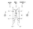
本実施の形態における電気式脱イオン水製造装置について図1を参照して説明する。図1は電気式脱イオン水製造装置の1例を示す模式図である。図1に示すように、カチオン交換膜3、中間イオン交換膜5及びアニオン交換膜4を離間して交互に配置し、カチオン交換膜3と中間イオン交換膜5で形成される空間内にイオン交換体8を充填して第1小脱塩室d1、d3、d5、d7を形成し、中間イオン交換膜5とアニオン交換膜4で形成される空間内にイオン交換体8を充填して第2小脱塩室d2、d4、d6、d8を形成し、第1小脱塩室d1と第2小脱塩室d2で脱塩室D1、第1小脱塩室d3と第2小脱塩室d4で脱塩室D2、第1小脱塩室d5と第2小脱塩室d6で脱塩室D3、第1小脱塩室d7と第2小脱塩室d8で脱塩室D4とする。また、脱塩室D2、D3のそれぞれ隣に位置するアニオン交換膜4とカチオン交換膜3で形成されるイオン交換体8aを充填した部分は濃縮水を流すための濃縮室1とする。これを順次併設して図中、左より脱塩室D1、濃縮室1、脱塩室D2、濃縮室1、脱塩室D3、濃縮室1、脱塩室D4を形成する。また、脱塩室D1の左にカチオン交換膜3を経て陰極室2aを、脱塩室D4の右にアニオン交換膜4を経て陽極室2bをそれぞれ設ける。また、中間イオン交換膜5を介して隣合う2つの小脱塩室において、第2小脱塩室の処理水流出ライン12は第1小脱塩室の被処理水流入ライン13に連接されている。
【0016】
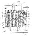
このような脱塩室は、図3に示すように、2つの枠体21、22と3つのイオン交換膜3、5、4によって形成される脱イオンモジュール20からなる。すなわち、第1枠体21の一側の面にカチオン交換膜3を封着し、第1枠体21の内部空間にイオン交換体を充填し、次いで、第1枠体21の他方の面に中間イオン交換膜5を封着して第1小脱塩室を形成する。次に中間イオン交換膜5を挟み込むように第2枠体22を封着し、第2枠体22の内部空間にイオン交換体を充填し、次いで、第2枠体22の他方の面にアニオン交換膜4を封着して第2小脱塩室を形成する。第1脱塩室及び第2小脱塩室に充填されるイオン交換体としては、特に制限されないが、被処理水が最初に流入する第2小脱塩室にはアニオン交換体を充填し、次いで、第2小脱塩室の流出水が流入する第1小脱塩室にはアニオン交換体とカチオン交換体の混合イオン交換体を充填することが、アニオン成分を多く含む被処理水、特に、シリカ、炭酸等の弱酸性成分を多く含む被処理水を十分に処理することができる点で好ましい。符号23は枠体補強用のリブである。
【0017】
また、濃縮室1は、網目状の陽イオン伝導スペーサと網目状の陰イオン伝導スペーサが濃縮水の流出入方向に対して、交互に積層充填される。これら網目状のイオン伝導スペーサの積層方法としては、特に制限されず、陰イオン伝導スペーサと陽イオン伝導スペーサの2床、陰イオン伝導スペーサと陽イオン伝導スペーサが交互に複数積層される複床のいずれであってもよい。また、濃縮室に充填される網目状のイオン伝導スペーサとしては、特に制限されず、2次元又は3次元の網目構造を有し、濃縮室に充填された場合、通水差圧を許容範囲内に保ちつつ、濃縮水に乱流を与えるもので、且つイオン交換基を有するものであればよく、例えば、ポリオレフィン系高分子を金型により斜交網状(メッシュ状)に成型し、この斜交網の表面に、イオン交換基を有するか、又はイオン交換基に転換可能な重合性単量体を、グラフト重合することにより得られるものが挙げられる。
【0018】
ポリオレフィン系高分子の斜交網を使用するイオン伝導スペーサにおいて、ポリオレフィン系高分子としては、特に制限されず、ポリプロピレン、ポリエチレン、ポエチレンテレフタレートなどが挙げられる。斜交網の形状としては、図2に示されるように、無数の線材が間隔mで配向する表側線材31と無数の線材が間隔nで配向する裏側線材32が各交点で図の如く交差し一体成型される平織りの斜交網30が例示される。表側線材同士の間隔mと、裏側線材同士の間隔nとは、同一であっても異なっていてもよいが、通常、同一である。また、斜交網30の厚みwは、これを1枚濃縮室に充填する場合、濃縮室の厚みとほぼ一致する。斜交網30の表面にグラフト重合させる重合性単量体は、イオン交換基を有するか、又はイオン交換基に転換可能な重合性単量体の中から選択できるが、例えば、カチオン交換基としては、スルホン基、カルボキシル基などが挙げられ、アニオン交換基としては、四級アンモニウム基、三級アミン基などが挙げられる。イオン交換基が導入された斜交網の目開きとしては、特に制限されないが、10〜90%、好ましくは30〜70%である。目開きが大きすぎると、当該濃縮室を区画する両側のイオン交換膜同士の電気的導通が得られず、イオンの移動がなく、濃縮水中のイオン濃度勾配を低減することはできない。一方、目開きが小さ過ぎると、濃縮水の通水差圧が許容以上に上昇してしまう点で好ましくない。イオン交換基が導入された斜交網は、濃縮室内に網目を両側のイオン交換膜に向けて充填されるが、その充填量は1枚であっても、複数枚を重ね合わせる充填のいずれであってもよい。また、斜交網は、図2のものの他、綾織状であってもよく、また、網目の形状は、菱形、四角形、円形、楕円形などが使用できる。網目形状が四角形の平織りの斜交網の場合、該四角形の一辺が約0.5〜5.0mm、好ましくは1.0〜3.0mm程度のものである。
【0019】
濃縮室1は、例えば、図3に示すように、1側のアニオン交換膜4と、他側のカチオン交換膜3で、定型寸法に切断された網目状のイオン伝導スペーサ81、82を挟み込んで作製される。図3では、網目状のイオン伝導スペーサは、上側の陰イオン伝導スペーサ81と下側の陽イオン伝導スペーサ82の2床の積層床8aからなる。すなわち、平板積層型の電気式脱イオン水製造装置の濃縮室内に、1枚の陽イオン伝導スペーサ81と陽イオン伝導スペーサ81と同じ大きさの1枚の陰イオン伝導スペーサ82の2床を積層充填する場合、2床で形成されるイオン伝導スペーサの縦横寸法は略両側のイオン交換膜3、4と同じであり、厚み寸法wが濃縮室内の厚みとなる。濃縮室1において、濃縮水の流出入方向に対して積層充填されるイオン伝導スペーサの順序としては、特に制限されず、濃縮水入口側から網目状の陽イオン伝導スペーサ、網目状の陰イオン伝導スペーサの順序でも、網目状の陰イオン伝導スペーサ、網目状の陽イオン伝導スペーサの順序でも、いずれでもよい。また、異なるイオン伝導スペーサ同士の端面部分は、大きな隙間が生じない限りは、特に制限されず、端面同士が当接あるいは近接させて、積層充填される。このように、網目状の陽イオン伝導スペーサ及び陰イオン伝導スペーサを両イオン交換膜で区画される濃縮室内に、均質に積層充填すれば、当該濃縮室を区画する両側のイオン交換膜同士の電気的導通が得られ、イオンの移動が行われ、濃縮水中のイオン濃度勾配を低減することができる。また、このイオン濃度の低減効果は、スペーサの網目形状に起因する乱流発生効果により、更に高められる。一方、濃縮室の厚さは、0.2〜8.0mm、好ましくは、0.5〜5.0mm、更に好ましくは0.8〜2.5mmである。濃縮室の厚さが0.2mm未満であると、例え、網目状の陽イオン伝導スペーサと網目状の陰イオン伝導スペーサを濃縮水の流出入方向に対して、交互に積層充填しても、スケール発生防止効果が得られ難くなり、通水差圧も発生し易い。また、8.0mmを越えると、電気抵抗が高くなり消費電力が増大する。
【0020】
前記電気式脱イオン水製造装置は、通常、以下のように運転される。すなわち、陰極6と陽極7間に直流電流を通じ、また被処理水流入ライン11から被処理水が流入すると共に、濃縮水流入ライン15から濃縮水が流入し、かつ陰極水流入ライン17a、陽極水流入ライン17bからそれぞれ陰極水、陽極水が流入する。被処理水流入ライン11から流入した被処理水は第2小脱塩室d2、d4、d6、d8を流下し、イオン交換体8の充填層を通過する際に不純物イオンが除去される。更に、第2小脱塩室の処理水流出ライン12を通った流出水は、第1小脱塩室の被処理水流入ライン13を通って第1小脱塩室d1、d3、d5、d7を流下し、ここでもイオン交換体8の充填層を通過する際に不純物イオンが除去され脱イオン水が脱イオン水流出ライン14から得られる。また、濃縮水流入ライン15から流入した濃縮水は各濃縮室1を上昇し、カチオン交換膜3及びアニオン交換膜4を介して移動してくる不純物イオン、更には後述するように、濃縮室内のイオン伝導スペーサを介して移動してくる不純物イオンを受け取り、不純物イオンを濃縮した濃縮水として濃縮室流出ライン16から流出され、さらに陰極水流入ライン17aから流入した陰極水は陰極水流出ライン18aから流出され、陽極水流入ライン17bから流入した陽極水は、陽極水流出ライン18bから流出される。上述の操作によって、被処理水中の不純物イオンは電気的に除去される。
【0021】
次に、本発明の電気式脱イオン水製造装置の濃縮室におけるスケール発生防止作用を図4〜図6を参照して説明する。図4は図1の電気式脱イオン水製造装置を更に簡略的に示した図、図5及び図6は図4の電気式脱イオン水製造装置の濃縮室における不純物イオンの移動を説明する図をそれぞれ示す。図4において、被処理水が最初に流入する第2小脱塩室d2、d4、d6にはアニオン交換体(A)を充填し、第2小脱塩室の流出水が流入する第1小脱塩室d1、d3、d5にはカチオン交換体とアニオン交換体の混合イオン交換体(M)を充填し、4つの濃縮室1には脱塩室の通水方向に沿って順に、網目状のアニオン伝導スペーサ単床(A)と網目状のカチオン伝導スペーサ単床(C)を交互に4床充填してある。
【0022】
図5において、濃縮室1の網目状アニオン伝導スペーサ単床領域1aではアニオン交換膜aを透過した炭酸イオンなどのアニオンは濃縮水中に移動せず、導電性の高いアニオン伝導スペーサAを通り、カチオン交換膜cまで移動し、アニオン伝導スペーサAとカチオン膜cの当接部分101において初めて濃縮水中に移動する(図5中、右向き矢印)。このため、炭酸イオンなどのアニオンはカチオン交換膜cに電気的に引き寄せられた状態で、濃縮室1から排出される。すなわち、アニオン伝導スペーサ単床領域1aにおける炭酸イオンなどのアニオンについて、濃縮水中の濃度勾配は図6の記号Xのように分布する。一方、アニオン伝導スペーサ単床領域1aにおいて、カチオン交換膜cを透過したカルシウムイオンなどのカチオンは濃縮水中を移動する。このため、カルシウムイオンの濃度が最も高くなる部分において、スケールを形成する対イオンである炭酸イオンはアニオン伝導スペーサ単床部分を移動するためスケールを発生し難い。
【0023】
同様に、濃縮室1のカチオン伝導スペーサ単床領域1bではカチオン交換膜cを透過したカルシウムイオンなどのカチオンは濃縮水中に移動せず、導電性の高いカチオン伝導スペーサCを通り、アニオン交換膜aまで移動し、カチオン伝導スペーサCとアニオン膜aの当接部分102において初めて濃縮水中に移動する(図5中、左向き矢印)。このため、カルシウムイオンなどのカチオンはアニオン交換膜aに電気的に引き寄せられた状態で、濃縮室1から排出される。すなわち、カチオン伝導スペーサ単床領域1bにおけるカルシウムイオンなどのカチオンについて、濃縮水中の濃度勾配は図6の記号Yのように分布する。一方、アニオン交換膜aを透過した炭酸イオンなどのアニオンは濃縮水中を移動する。このため、炭酸イオンの濃度が最も高くなる部分において、スケールを形成する対イオンであるカルシウムイオンはカチオン伝導スペーサ単床部分を移動するためスケールを発生し難い。更に、濃縮室内に充填しているイオン伝導スペーサは、網目状形状であるため、濃縮水の流れが乱流となり易く、炭酸イオンやカルシウムイオンなどの濃度勾配をより大きく低減できると共に、イオン交換膜面に付着しようとするスケール成分をかきとる効果を有するため、スケールの発生をより抑制する。このようなイオン移動は、マグネシウムイオン、水素イオン、水酸化物イオンにおいても同様である。また、濃縮室内部にアニオン伝導スペーサ単床領域1aとカチオン伝導スペーサ単床領域1bを積層することによって、カチオン伝導スペーサが充填された部分に移動してきたアニオンは導電性の低い濃縮水を移動するよりも、導電性の高いアニオン交換膜を伝わり、アニオン伝導スペーサ単床領域1aまで達し、ここで導電性の高いアニオン交換体を移動する。このイオンの移動形態はカチオンについても同様である。すなわち、濃縮水中を通って対面のイオン交換膜付近に移動するイオンはほとんどなく、ほとんどのイオンはカチオン伝導スペーサ、アニオン伝導スペーサを通って対面のイオン交換膜付近まで移動する。なお、図5及び図6中、濃縮室1において、カチオン交換膜a及びアニオン交換膜cと、網目状の陽イオン伝導スペーサ単床領域1a又は網目状の陰イオン伝導スペーサ単床領域1bとの間に隙間が形成されているが、これはイオン伝導スペーサの積層充填状態を判りやすくするため設けたものであり、実際は、密着状態であり、このような隙間は存在しない。
【0024】
従来の電気式脱イオン水製造装置では、イオン交換体を再生する目的で印加している電流が水の電気分解を促進し、イオン伝導性を示さない網目状スペーサを充填した濃縮室のイオン交換膜表面でpHシフトを引き起こし、アニオン交換膜近傍ではpHが高く、カチオン交換膜近傍ではpHが低くなり、且つ図7に示すように炭酸イオンとカルシウムイオンが共に、高い濃度勾配で接することから、濃縮室側のアニオン交換膜表面でスケールが発生し易くなっていた。しかしながら、本例では、前述の如く、濃縮水中のカチオン濃度が最も高いと思われるアニオン交換膜a表面近傍の濃縮水中には、高い濃度の炭酸イオンなどのアニオンが存在しないから、濃縮室内において、炭酸イオンとカルシウムイオンが結合して炭酸カルシウムを生成することがない(図6参照)。従って、本例の電気式脱イオン水製造装置を長時間連続運転しても、濃縮室にスケールが発生することはない。
【0025】
また、濃縮室1はイオン伝導スペーサ8aの均質で密着した充填により両側に位置するカチオン交換膜3とアニオン交換膜4を電気的に導通するため、導電性が高まり、脱塩室の入口側から出口側の全体に渡り電流密度を均一化でき、消費電力を低減できる。
【0026】
本発明において、被処理水の第1小脱塩室及び第2小脱塩室での流れ方向は、特に制限されず、上記実施の形態の他、第1小脱塩室と第2小脱塩室での流れ方向が異なっていてもよい。また、被処理水が流入する小脱塩室は、上記実施の形態例の他、先ず、被処理水を第1小脱塩室に流入させ、流下した後、第1小脱塩室の流出水を第2小脱塩室に流入させてもよい。また、濃縮水の流れ方向も適宜決定される。
【0027】
本発明の実施の形態における他の電気式脱イオン水製造装置を図8を参照して説明する。図8の電気式脱イオン水製造装置100は、図1に示される省電力型電気式脱イオン水製造装置10における中間イオン交換膜を省略した形態であり、脱塩室内における被処理水の流れが1パスである。すなわち、電気式脱イオン水製造装置100において、一側のカチオン交換膜101、及び他側のアニオン交換膜102で区画される室にイオン交換体103を充填して脱塩室104を構成し、カチオン交換膜101、アニオン交換膜102を介して脱塩室104の両側に濃縮室105を設け、これらの脱塩室104及び濃縮室105を陽極110を備えた陽極室と陰極109を備えた陰極室の間に配置し、電圧を印加しながら脱塩室104に被処理水を流入すると共に、濃縮室105に濃縮水を流入して被処理水中の不純物イオンを除去し、脱イオン水を得る方法において、濃縮室105は、上記実施の形態例と同様の構成を採ることにより、同様の作用効果を奏する。なお、符号111は被処理水流入ライン、114は脱イオン水流出ライン、115は濃縮水流入ライン、116は濃縮水流出ライン、117は電極水流入ライン、118は電極水流出ラインをそれぞれ示す。また、本発明の電気式脱イオン水製造装置の形態としては、特に制限されず、スパイラル型、同心円型及び平板積層型などのものが挙げられる。
【0028】
本発明の脱イオン水製造方法に用いる被処理水としては、特に制限されず、例えば、井水、水道水、下水、工業用水、河川水、半導体製造工場の半導体デバイスなどの洗浄排水又は濃縮室からの回収水などを逆浸透膜処理した透過水、また、半導体製造工場等のユースポイントで使用された回収水であって、逆浸透膜処理がされていない水が挙げられる。このようにして供給される被処理水の一部を濃縮水としても使用する場合、脱塩室に供給される被処理水及び濃縮室に供給される濃縮水を軟化後、使用することがスケール発生を更に抑制できる点で好ましい。軟化の方法は、特に限定されないが、ナトリウム形のイオン交換樹脂等を用いた軟化器が好適である。
【0029】
【実施例】
実施例1
下記装置仕様及び運転条件において、図8と同様の構成で6個の脱イオンモジュールを並設して構成される電気式脱イオン水製造装置を使用した。被処理水は、工業用水の逆浸透膜透過水を用い、その硬度は、200μgCaCO3/l であった。また、被処理水の一部を濃縮水及び電極水として使用した。運転時間は4000時間であり、4000時間後の濃縮室内のスケール発生の有無を観察した。また、同時間における抵抗率17.9MΩ-cm の処理水を得るための運転条件を表1に示す。
【0030】
(運転の条件)
・電気式脱イオン水製造装置;試作EDI
・脱塩室;幅300mm、高さ600mm、厚さ3mm
・脱塩室に充填したイオン交換樹脂;アニオン交換樹脂(A)とカチオン
交換樹脂(K)の混合イオン交換樹脂(混合比は体積比でA:K=1:1)
・濃縮室;幅300mm、高さ600mm、厚さ1mm
・濃縮室充填イオン伝導スペーサ;網目状のカチオン伝導スペーサ単床と網目のアニオン伝導スペーサ単床を濃縮水の流出入方向に沿って交互に積層した4床
・装置全体の流量;1m3/h
【0031】
実施例2
下記装置仕様及び運転条件において、図1と同様の構成で3個の脱イオンモジュール(6個の小脱塩室)を並設して構成される電気式脱イオン水製造装置を使用した。被処理水は、工業用水の逆浸透膜透過水を用い、その硬度は、200μgCaCO3/l であった。また、被処理水の一部を濃縮水及び電極水として使用した。運転時間は4000時間であり、4000時間後の濃縮室内のスケール発生の有無を観察した。また、同時間における抵抗率17.9MΩ-cm の処理水を得るための運転条件を表1に示す。
【0032】
(運転の条件)
・電気式脱イオン水製造装置;試作EDI
・中間イオン交換膜;アニオン交換膜
・第1小脱塩室;幅300mm、高さ600mm、厚さ3mm
・第1小脱塩室に充填したイオン交換樹脂;アニオン交換樹脂(A)とカチオン
交換樹脂(K)の混合イオン交換樹脂(混合比は体積比でA:K=1:1)
・第2小脱塩室;幅300mm、高さ600mm、厚さ8mm
・第2小脱塩室充填イオン交換樹脂;アニオン交換樹脂
・濃縮室;幅300mm、高さ600mm、厚さ1mm
・濃縮室充填イオン伝導スペーサ;網目状のカチオン伝導スペーサ単床と網目状のアニオン伝導スペーサ単床を濃縮水の流出入方向に沿って交互に積層した4床
・装置全体の流量;1m3/h
【0033】
比較例1
網目状のイオン伝導スペーサの代わりに、イオン伝導性のない網目状スペーサを濃縮室に充填した以外は、実施例1と同様の方法で行った。運転時間は4000時間であり、4000時間後の濃縮室内のスケール発生の有無を観察した。また、同時間における抵抗率17.9MΩ-cm の処理水を得るための運転条件を表1に示す。イオン伝導性のない網目状スペーサは、実施例1で使用した網目状のイオン伝導スペーサの製作過程で得られるイオン交換基導入前のものである。
【0034】
比較例2
網目状のイオン伝導スペーサの代わりに、イオン伝導性のない網目状スペーサを濃縮室に充填した以外は、実施例2と同様の方法で行った。運転時間は4000時間であり、4000時間後の濃縮室内のスケール発生の有無を観察した。また、同時間における抵抗率17.9MΩ-cm の処理水を得るための運転条件を表1に示す。イオン伝導性のない網目状スペーサは、実施例1で使用した網目状のイオン伝導スペーサの製作過程で得られるイオン交換基導入前のものである。
【0035】
【表1】
【発明の効果】
本発明によれば、スケール発生の問題を、被処理水からの対策ではなく、電気式脱イオン水製造装置の濃縮室の構造面から解決でき、長期間の連続運転においても、濃縮室内にスケール発生を認めることなく、安定した運転ができる。また、濃縮室内の導電性が高まり、脱塩室の入口側から出口側の全体に渡り電流密度を均一化でき、消費電力を低減できる。
【図面の簡単な説明】
【図1】本発明の実施の形態における電気式脱イオン水製造装置の模式図である。
【図2】斜交網の形状を説明する図である。
【図3】脱塩室モジュール及び濃縮室の構造を説明する図である。
【図4】図1の電気式脱イオン水製造装置を簡略的に示した図である。
【図5】濃縮室における不純物イオンの移動を説明する図である。
【図6】濃縮室における不純物イオンの濃度勾配を示す図である。
【図7】イオン伝導性のない網目状スペーサを充填した濃縮室(従来型)における不純物イオンの濃度勾配を示す図である。
【図8】本発明の他の実施の形態における電気式脱イオン水製造装置の模式図である。
【符号の説明】
D、D1〜D4、104 脱塩室
d1、d3、d5、d7 第1小脱塩室
d2、d4、d6、d8 第2小脱塩室
1、105 濃縮室
2 電極室
3、101 カチオン膜
4、102 アニオン膜
5 中間イオン交換膜
6、109 陰極
7、110 陽極
8、103 イオン交換体
8a カチオン伝導スペーサ単床とアニオン伝導スペーサ単床の積層床
10、100 電気式脱イオン水製造装置
11、111 被処理水流入ライン
12 第2小脱塩室の処理水流出ライン
13 第1小脱塩室の被処理水流入ライン
14、114 脱イオン水流出ライン
15、115 濃縮水流入ライン
16、116 濃縮水流出ライン
17a、17b、117 電極水流入ライン
18a、18b、118 電極水流出ライン
20 脱イオンモジュール
30 斜交網
101 炭酸イオンが濃縮水中に初めて移動する点
102 カルシウムイオンが濃縮水中に初めて移動する点[0001]
BACKGROUND OF THE INVENTION
The present invention relates to a scale generation prevention type electric deionized water production apparatus and deionized water used in various industries such as semiconductor manufacturing field, pharmaceutical manufacturing field, power generation field such as nuclear power and thermal power, food industry, etc. It is related with the manufacturing method.
[0002]
[Prior art]
As a method for producing deionized water, there is conventionally known a method in which deionized water is passed through an ion exchange resin to be treated. In this method, regeneration is performed with a drug when the ion exchange resin is saturated with ions. In order to eliminate such disadvantages in processing operations, a method for producing deionized water by an electric deionization method which does not require any regeneration by a chemical agent has been established and has been put into practical use.
[0003]
This electric deionized water production apparatus comprises a cation exchange membrane on one side and an ion exchanger filled in one chamber defined by an anion exchange membrane on the other side to form a demineralization chamber. Concentration chambers are provided on both sides of the desalting chamber via an anion exchange membrane, and these desalting chambers and concentrating chambers are arranged between an anode chamber equipped with an anode and a cathode chamber equipped with a cathode. The water to be treated flows into the desalting chamber while applying a voltage, and the concentrated water flows into the concentration chamber to remove impurity ions in the water to be treated, thereby obtaining deionized water.
[0004]
In recent years, a conventional type in which a cation exchange membrane and an anion exchange membrane are alternately arranged apart from each other, and every other ion exchanger is filled in a space formed by the cation exchange membrane and the anion exchange membrane to form a desalination chamber. Instead of the electric deionized water production apparatus, a power-saving electric deionized water production apparatus has been developed in which the structure of the demineralization chamber is drastically modified. This power-saving electric deionized water production apparatus is partitioned by a cation exchange membrane on one side, an anion exchange membrane on the other side, and an intermediate ion exchange membrane located between the cation exchange membrane and the anion exchange membrane. Two small desalting chambers are filled with ion exchangers to form a desalting chamber, and concentration chambers are provided on both sides of the desalting chamber via the cation exchange membrane and anion exchange membrane. The chamber is arranged between an anode chamber equipped with an anode and a cathode chamber equipped with a cathode, and water to be treated flows into one small desalination chamber while applying a voltage, The effluent water from the salt chamber flows into the other small desalination chamber, and the concentrated water flows into the concentration chamber to remove impurity ions in the water to be treated, thereby obtaining deionized water. According to the electric deionized water production apparatus having such a structure, the ion exchanger filled in at least one of the two small desalting chambers is, for example, only an anion exchanger or only a cation exchanger. Single ion exchanger such as anion exchanger or mixed exchanger of anion exchanger and cation exchanger, reducing the electrical resistance for each type of ion exchanger, and at the optimum thickness for obtaining high performance Can be set.
[0005]
On the other hand, when the hardness of the water to be treated flowing into such an electric deionized water production apparatus is high, scales such as calcium carbonate and magnesium hydroxide are generated in the concentration chamber of the electric deionized water production apparatus. When the scale occurs, the electrical resistance at that portion increases, and current does not flow easily. That is, in order to pass the same current value as when no scale is generated, it is necessary to increase the voltage, which increases power consumption. In addition, the current density differs in the concentration chamber depending on the place where the scale is attached, and the current becomes non-uniform in the desalting chamber. Further, when the amount of scale adhesion further increases, the water flow differential pressure increases, and the voltage further increases. When the maximum voltage value of the apparatus is exceeded, the current value decreases. In this case, the current value necessary for ion removal cannot flow, and the quality of the treated water is deteriorated. Furthermore, the grown scale erodes into the ion exchange membrane, and eventually breaks the ion exchange membrane.
[0006]
[Problems to be solved by the invention]
As one countermeasure for solving such a problem, there is a method in which water to be treated having low hardness flows into an electric deionized water production apparatus. Such treated water with low hardness does not reach the solubility product in the concentrating chamber, so scale cannot occur. However, actually, even when the water to be treated having such low hardness is passed, scales such as calcium carbonate and magnesium hydroxide may be generated in the concentration chamber. In this case, a serious problem occurs as described above. The generation of such a scale is a serious problem that is observed in both the conventional electric deionized water production apparatus and the power-saving electric deionized water production apparatus. On the other hand, in a concentrating chamber partitioned by a cation exchange membrane and an anion exchange membrane of a conventional electric deionized water production apparatus, a network cation conductive spacer is provided on the cation exchange membrane side and a network anion conduction is provided on the anion exchange membrane side. A method for filling the spacer is known. According to this method, it is possible to secure a flow path in the concentration chamber and reduce the voltage. However, it is not sufficient in terms of prevention of scale generation, and the serious problem that scale is generated on the cation conductive spacer and the anion conductive spacer has not been solved.
[0007]
Accordingly, an object of the present invention is to solve the problem of scale generation from the structure of the concentration chamber of the electric deionized water production apparatus, not from measures against the treated water. Another object of the present invention is to provide an electric deionized water production apparatus and a deionized water production method that do not generate scale.
[0008]
[Means for Solving the Problems]
In such a situation, the present inventors have conducted intensive studies, and as a result, a mesh-like cation conductive spacer and a mesh-like negative ion flow into the concentration chamber of the electric deionized water production apparatus in the flow direction of the concentrate. If the ion conductive spacers are alternately stacked and filled, the effect of generating turbulent flow due to the mesh shape of the spacers and the effect of alternately stacking the concentrated water flowing in and out of the cation conductive spacer and the anion conductive spacer, The concentration gradient of carbonate ions and calcium ions in the concentrated water can be greatly reduced, and it has been found that no scale is generated in the concentration chamber even during long-term continuous operation, and the present invention has been completed.
[0009]
That is, the present invention (1) is to form a desalination chamber by filling an ion exchanger into a chamber defined by a cation exchange membrane on one side and an anion exchange membrane on the other side. Electric deionized water production in which concentration chambers are provided on both sides of a desalination chamber through a membrane, and these demineralization chambers and concentration chambers are arranged between an anode chamber equipped with an anode and a cathode chamber equipped with a cathode In the apparatus, the concentrating chamber provides electric deionization formed by alternately laminating and filling a mesh-like cation conducting spacer and a mesh-like anion conducting spacer in the flow direction of concentrated water. Is. By adopting such a configuration, the anion that has permeated through the anion exchange membrane does not move into the concentrated water in the network-like anion conductive spacer region of the concentration chamber, but moves to the cation exchange membrane through the highly conductive anion conductive spacer. This is the first time to move into concentrated water. Similarly, in the network-like cation conductive spacer region, cations that have permeated through the cation exchange membrane do not move into the concentrated water, but pass through the highly conductive cation conductive spacer to the anion exchange membrane. Moving. For this reason, in the concentration chamber, for example, the concentration gradient of carbonate ions and calcium ions in the liquid is greatly reduced, and collisions at high concentration portions are avoided. Further, as described above, the ions that have moved to the cation exchange membrane or the anion exchange membrane are sufficiently stirred due to the turbulent flow generation effect due to the mesh shape of the spacer, which prevents the scale from accumulating in the concentrating chamber. Scales such as calcium are less likely to occur.
[0010]
In addition, the present invention (2) includes two small desalinations partitioned by a cation exchange membrane on one side, an anion exchange membrane on the other side, and an intermediate ion exchange membrane located between the cation exchange membrane and the anion exchange membrane. The chamber is filled with an ion exchanger to form a desalting chamber. Concentration chambers are provided on both sides of the desalting chamber via the cation exchange membrane and anion exchange membrane, and the desalting chamber and the concentration chamber are provided with an anode. In the electric deionized water production apparatus arranged between a positive electrode chamber and a negative electrode chamber having a cathode, the concentrating chamber has a reticulated cation conductive spacer and a reticulated anion conductive spacer. The present invention provides an electric deionized water production apparatus that is formed by alternately laminating and filling in the inflow / outflow direction. By adopting such a configuration, the same effect as that of the present invention can be achieved in the power-saving electric deionized water production apparatus. In addition, the ion exchanger filled in at least one of the two small desalting chambers is a cation exchange with a single ion exchanger or an anion exchanger such as only an anion exchanger or only a cation exchanger. It can be set as a mixed exchanger of the body, and can be set to an optimum thickness for reducing the electric resistance and obtaining high performance for each kind of the ion exchanger. In addition, the concentrating chamber is more conductive, the current density can be made uniform from the inlet side to the outlet side of the desalting chamber, and the power consumption can be further reduced.
[0011]
Further, in the present invention (3), the ion exchanger filled in one small desalting chamber partitioned by the intermediate ion exchange membrane and the anion exchange membrane on the other side is an anion exchanger, and the one side The ion exchanger filled in the other small desalting chamber defined by the cation exchange membrane and the intermediate ion exchange membrane is a mixture of a cation exchanger and an anion exchanger. A water production apparatus is provided. By adopting such a configuration, in addition to the same effects as the above-described invention, water to be treated containing a large amount of anionic components, particularly water to be treated containing a large amount of weakly acidic components such as silica and carbonic acid can be sufficiently treated. .
[0012]
Moreover, this invention (4) provides the electric deionized water manufacturing apparatus as described in said (1)-(3) whose thickness of the said concentration chamber is 0.2-8.0 mm. By adopting such a configuration, it is possible to reduce the electrical resistance, prevent the generation of scale, and determine the optimum concentration chamber thickness without increasing the water flow differential pressure.
[0013]
In addition, the present invention (5) comprises a desalination chamber by filling a chamber partitioned by a cation exchange membrane on one side and an anion exchange membrane on the other side to form a desalination chamber. Concentration chambers are provided on both sides of the desalting chamber through a membrane, and these desalting chambers and concentrating chambers are arranged between an anode chamber equipped with an anode and a cathode chamber equipped with a cathode, and desalting is performed while applying a voltage. In the method of obtaining the deionized water by flowing the treated water into the chamber and removing the impurity ions in the treated water by flowing the concentrated water into the concentrating chamber, the concentrating chamber includes a mesh-like cation conductive spacer and The present invention provides a method for producing deionized water in which a net-like anion conductive spacer is formed by alternately laminating and filling in the flow of concentrated water in and out. By adopting such a configuration, the same effect as the invention (1) is obtained.
[0014]
In addition, the present invention (6) includes two small desalinations partitioned by a cation exchange membrane on one side, an anion exchange membrane on the other side, and an intermediate ion exchange membrane located between the cation exchange membrane and the anion exchange membrane. The chamber is filled with an ion exchanger to form a desalting chamber. Concentration chambers are provided on both sides of the desalting chamber via the cation exchange membrane and anion exchange membrane, and the desalting chamber and the concentration chamber are provided with an anode. The water to be treated flows into one small desalination chamber while applying a voltage, and then the effluent from the small desalination chamber is removed from the other small desalination chamber. In the method of obtaining concentrated deionized water by flowing concentrated water into the concentration chamber and removing deionized water by flowing concentrated water into the concentration chamber, the concentration chamber includes a mesh-like cation conductive spacer and a mesh-like cation conductive spacer. Anion conducting spacers are alternately stacked and filled in the direction of concentrated water flow Method for producing deionized water are those formed Te and provides a. By adopting such a configuration, the same effects as those of the invention (2) can be obtained.
[0015]
DETAILED DESCRIPTION OF THE INVENTION
The electric deionized water production apparatus in the present embodiment will be described with reference to FIG. FIG. 1 is a schematic view showing an example of an electric deionized water production apparatus. As shown in FIG. 1, the
[0016]
As shown in FIG. 3, such a desalting chamber includes a
[0017]
Further, in the concentrating
[0018]
In the ion conductive spacer using an oblique network of polyolefin polymer, the polyolefin polymer is not particularly limited, and examples thereof include polypropylene, polyethylene, and polyethylene terephthalate. As shown in FIG. 2, the shape of the oblique network is such that a
[0019]
For example, as shown in FIG. 3, the concentrating
[0020]
The electric deionized water production apparatus is usually operated as follows. That is, a direct current is passed between the
[0021]
Next, the scale generation preventing action in the concentration chamber of the electric deionized water production apparatus of the present invention will be described with reference to FIGS. 4 is a diagram showing the electric deionized water production apparatus of FIG. 1 in a more simplified manner, and FIGS. 5 and 6 are diagrams for explaining the movement of impurity ions in the concentration chamber of the electric deionized water production apparatus of FIG. Respectively. In FIG. 4, the second small desalination chamber d into which the water to be treated flows first.2 , DFour , D6 Is filled with an anion exchanger (A), and the first small desalting chamber d into which the effluent of the second small desalting chamber flows.1 , DThree , DFive Is filled with a mixed ion exchanger (M) of a cation exchanger and an anion exchanger, and the four concentrating
[0022]
In FIG. 5, in the mesh-like anion conducting spacer single-bed region 1a of the concentrating
[0023]
Similarly, in the cation conductive spacer single-bed region 1b of the
[0024]
In a conventional electric deionized water production system, the current applied for the purpose of regenerating the ion exchanger accelerates the electrolysis of the water, and ion exchange in the concentrating chamber filled with mesh spacers that do not exhibit ion conductivity. Since the pH shift is caused on the membrane surface, the pH is high in the vicinity of the anion exchange membrane, the pH is low in the vicinity of the cation exchange membrane, and both carbonate ions and calcium ions are in contact with each other with a high concentration gradient as shown in FIG. Scale was easily generated on the surface of the anion exchange membrane on the concentration chamber side. However, in this example, as described above, the concentrated water near the surface of the anion exchange membrane a, which is considered to have the highest cation concentration in the concentrated water, does not contain anions such as carbonate ions having a high concentration. Carbonate ions and calcium ions are not combined to produce calcium carbonate (see FIG. 6). Therefore, even if the electric deionized water production apparatus of this example is continuously operated for a long time, scale does not occur in the concentration chamber.
[0025]
In addition, the concentrating
[0026]
In the present invention, the flow direction in the first small desalination chamber and the second small desalination chamber of the water to be treated is not particularly limited, and in addition to the above embodiment, the first small desalination chamber and the second small desalination chamber. The flow direction in the salt chamber may be different. In addition to the above embodiment, the small desalination chamber into which the water to be treated flows first flows the water to be treated into the first small desalination chamber and then flows down, and then flows out of the first small desalination chamber. Water may flow into the second small desalting chamber. Further, the flow direction of the concentrated water is also appropriately determined.
[0027]
Another electric deionized water production apparatus in the embodiment of the present invention will be described with reference to FIG. The electric deionized
[0028]
The treated water used in the deionized water production method of the present invention is not particularly limited. For example, well water, tap water, sewage, industrial water, river water, washing waste water or concentration chambers for semiconductor devices in semiconductor manufacturing plants, etc. Permeated water obtained by treating the recovered water from the reverse osmosis membrane, or recovered water used at a point of use such as a semiconductor manufacturing plant, which is not subjected to the reverse osmosis membrane treatment. When a part of the treated water supplied in this way is also used as concentrated water, it is scaled to use the treated water supplied to the desalting chamber and the concentrated water supplied to the concentrating chamber after softening. It is preferable in that generation can be further suppressed. The softening method is not particularly limited, but a softener using a sodium ion exchange resin or the like is suitable.
[0029]
【Example】
Example 1
In the following apparatus specifications and operating conditions, an electric deionized water production apparatus configured by arranging six deionization modules in parallel with the same configuration as in FIG. 8 was used. The treated water is reverse osmosis membrane permeated water for industrial water, and its hardness is 200 μg CaCOThree / L. Moreover, some treated water was used as concentrated water and electrode water. The operation time was 4000 hours, and the occurrence of scale in the concentration chamber after 4000 hours was observed. Table 1 shows the operating conditions for obtaining treated water having a resistivity of 17.9 MΩ-cm at the same time.
[0030]
(Operating conditions)
・ Electric deionized water production equipment; prototype EDI
・ Desalination chamber: width 300mm, height 600mm, thickness 3mm
・ Ion exchange resin filled in desalination chamber; anion exchange resin (A) and cation
Exchange resin (K) mixed ion exchange resin (mixing ratio is A: K = 1: 1 by volume)
・ Concentration chamber: width 300mm, height 600mm, thickness 1mm
-Concentrated chamber filling ion conducting spacer: 4 beds in which mesh-like cation conducting spacer single beds and mesh anion conducting spacer single beds are alternately stacked along the flow direction of concentrated water
・ Flow rate of the entire device: 1mThree / H
[0031]
Example 2
In the following apparatus specifications and operating conditions, an electric deionized water production apparatus constituted by arranging three deionization modules (six small demineralization chambers) in parallel with the same configuration as in FIG. 1 was used. The treated water is reverse osmosis membrane permeated water for industrial water, and its hardness is 200 μg CaCOThree / L. Moreover, some treated water was used as concentrated water and electrode water. The operation time was 4000 hours, and the occurrence of scale in the concentration chamber after 4000 hours was observed. Table 1 shows the operating conditions for obtaining treated water having a resistivity of 17.9 MΩ-cm at the same time.
[0032]
(Operating conditions)
・ Electric deionized water production equipment; prototype EDI
・ Intermediate ion exchange membrane; anion exchange membrane
・ First small desalination chamber: width 300mm, height 600mm, thickness 3mm
-Ion exchange resin filled in the first small desalting chamber; anion exchange resin (A) and cation
Exchange resin (K) mixed ion exchange resin (mixing ratio is A: K = 1: 1 by volume)
・ Second small desalination chamber; width 300mm, height 600mm, thickness 8mm
・ Second small desalination chamber filled ion exchange resin; anion exchange resin
・ Concentration chamber: width 300mm, height 600mm, thickness 1mm
-Concentrated chamber filling ion conducting spacer: 4 beds in which reticulated cation conducting spacer single beds and reticulated anion conducting spacer single beds are alternately stacked along the flow direction of concentrated water
・ Flow rate of the entire device: 1mThree / H
[0033]
Comparative Example 1
The same procedure as in Example 1 was performed, except that a reticulated spacer without ion conductivity was filled in the concentrating chamber instead of the reticulated ion conductive spacer. The operation time was 4000 hours, and the occurrence of scale in the concentration chamber after 4000 hours was observed. Table 1 shows the operating conditions for obtaining treated water having a resistivity of 17.9 MΩ-cm at the same time. The mesh spacer without ion conductivity is the one before the introduction of ion exchange groups obtained in the production process of the mesh ion conduction spacer used in Example 1.
[0034]
Comparative Example 2
The same procedure as in Example 2 was performed, except that a reticulated spacer without ion conductivity was filled in the concentrating chamber instead of the reticulated ion conductive spacer. The operation time was 4000 hours, and the occurrence of scale in the concentration chamber after 4000 hours was observed. Table 1 shows the operating conditions for obtaining treated water having a resistivity of 17.9 MΩ-cm at the same time. The mesh spacer without ion conductivity is the one before the introduction of ion exchange groups obtained in the production process of the mesh ion conduction spacer used in Example 1.
[0035]
[Table 1]
【The invention's effect】
According to the present invention, the problem of scale generation can be solved from the structural aspect of the concentration chamber of the electric deionized water production apparatus, not the countermeasure from the water to be treated. Stable operation is possible without any occurrence. Further, the conductivity in the concentrating chamber is increased, the current density can be made uniform from the inlet side to the outlet side of the desalting chamber, and the power consumption can be reduced.
[Brief description of the drawings]
FIG. 1 is a schematic diagram of an electric deionized water production apparatus according to an embodiment of the present invention.
FIG. 2 is a diagram for explaining the shape of an oblique network.
FIG. 3 is a diagram illustrating the structure of a desalination chamber module and a concentration chamber.
FIG. 4 is a diagram schematically showing the electric deionized water production apparatus of FIG. 1;
FIG. 5 is a diagram for explaining the movement of impurity ions in the concentration chamber.
FIG. 6 is a diagram showing a concentration gradient of impurity ions in a concentration chamber.
FIG. 7 is a diagram showing a concentration gradient of impurity ions in a concentration chamber (conventional type) filled with a mesh spacer without ion conductivity.
FIG. 8 is a schematic diagram of an electrical deionized water production apparatus according to another embodiment of the present invention.
[Explanation of symbols]
D, D1 ~
d1 , DThree , DFive , D7 First small desalination chamber
d2 , DFour , D6 , D8 Second small desalination chamber
1,105 Concentration chamber
2 Electrode chamber
3, 101 Cationic membrane
4,102 Anion membrane
5 Intermediate ion exchange membrane
6, 109 cathode
7, 110 Anode
8, 103 Ion exchanger
8a Laminate floor of single cation conductive spacer and anion conductive spacer
10, 100 Electric deionized water production equipment
11, 111 Untreated water inflow line
12 Process water outflow line of the second small desalination chamber
13 Processed water inflow line of the first small desalination chamber
14,114 Deionized water outflow line
15, 115 Concentrated water inflow line
16, 116 Concentrated water outflow line
17a, 17b, 117 electrode water inflow line
18a, 18b, 118 Electrode water outflow line
20 Deionization module
30 Oblique network
101 Points where carbonate ions move into concentrated water for the first time
102 Points where calcium ions move into concentrated water for the first time
Claims (6)
Translated fromJapanesePriority Applications (1)
| Application Number | Priority Date | Filing Date | Title |
|---|---|---|---|
| JP2001351223AJP3781352B2 (en) | 2001-11-16 | 2001-11-16 | Electric deionized water production apparatus and deionized water production method |
Applications Claiming Priority (1)
| Application Number | Priority Date | Filing Date | Title |
|---|---|---|---|
| JP2001351223AJP3781352B2 (en) | 2001-11-16 | 2001-11-16 | Electric deionized water production apparatus and deionized water production method |
Publications (2)
| Publication Number | Publication Date |
|---|---|
| JP2003145164A JP2003145164A (en) | 2003-05-20 |
| JP3781352B2true JP3781352B2 (en) | 2006-05-31 |
Family
ID=19163557
Family Applications (1)
| Application Number | Title | Priority Date | Filing Date |
|---|---|---|---|
| JP2001351223AExpired - Fee RelatedJP3781352B2 (en) | 2001-11-16 | 2001-11-16 | Electric deionized water production apparatus and deionized water production method |
Country Status (1)
| Country | Link |
|---|---|
| JP (1) | JP3781352B2 (en) |
Families Citing this family (9)
| Publication number | Priority date | Publication date | Assignee | Title |
|---|---|---|---|---|
| JP3781361B2 (en)* | 2002-02-08 | 2006-05-31 | オルガノ株式会社 | Electric deionized water production equipment |
| US7404884B2 (en)* | 2003-04-25 | 2008-07-29 | Siemens Water Technologies Holding Corp. | Injection bonded articles and methods |
| US8066860B2 (en)* | 2006-09-22 | 2011-11-29 | General Electric Company | Arrangement of ion exchange material within an electrodeionization apparatus |
| JP5377230B2 (en)* | 2009-10-30 | 2013-12-25 | 株式会社アストム | Flow-through laminated sheet |
| JP5393576B2 (en)* | 2010-04-16 | 2014-01-22 | オルガノ株式会社 | Electric deionized water production equipment |
| JP5489867B2 (en)* | 2010-06-03 | 2014-05-14 | オルガノ株式会社 | Electric deionized water production equipment |
| ITPD20130065A1 (en) | 2013-03-15 | 2014-09-16 | Idropan Dell Orto Depuratori S R L | EQUIPMENT FOR THE PURIFICATION OF A FLUID AND A PURIFICATION METHOD OF A FLUID, IN PARTICULAR THROUGH THE ABOVE EQUIPMENT |
| US9878927B2 (en) | 2013-03-15 | 2018-01-30 | Idropan Dell'orto Depuratori S.R.L | Apparatus for purifying a fluid and method for purifying a fluid, in particular by means of the aforesaid apparatus |
| CN105417635B (en) | 2014-09-15 | 2021-02-02 | 伊德罗帕德尔园林清洗有限公司 | Device for purifying a fluid and method for purifying a fluid by means of the same |
- 2001
- 2001-11-16JPJP2001351223Apatent/JP3781352B2/ennot_activeExpired - Fee Related
Also Published As
| Publication number | Publication date |
|---|---|
| JP2003145164A (en) | 2003-05-20 |
Similar Documents
| Publication | Publication Date | Title |
|---|---|---|
| JP3385553B2 (en) | Electric deionized water production apparatus and deionized water production method | |
| JP3781361B2 (en) | Electric deionized water production equipment | |
| KR100409416B1 (en) | Manufacturing method of deionized water by electric deionization method | |
| JP3794268B2 (en) | Electrodeionization apparatus and operation method thereof | |
| JP6078074B2 (en) | Desalination system and method | |
| JP2004082092A (en) | Electric deionizer | |
| JP2004216302A (en) | Electrodeionization equipment and water treatment equipment | |
| JP2010201361A (en) | Apparatus for manufacturing electric deionized water and method for manufacturing deionized water using the apparatus | |
| WO1997046492A1 (en) | Process for producing deionized water by electrical deionization technique | |
| WO1997046491A1 (en) | Process for producing deionized water by electrical deionization technique | |
| JP3721883B2 (en) | Electrodeionization equipment | |
| JP2020078772A (en) | Electrodeionization device and method for producing deionized water using the same | |
| JP4400218B2 (en) | Electric deionization apparatus and deionization method | |
| JP3305139B2 (en) | Method for producing deionized water by electrodeionization method | |
| JP3781352B2 (en) | Electric deionized water production apparatus and deionized water production method | |
| JP4250922B2 (en) | Ultrapure water production system | |
| JPH08150326A (en) | Production of deionized water by electrolytic deionization method | |
| JP4597388B2 (en) | Electric deionized water production apparatus and deionized water production method | |
| JP2014000524A (en) | Electric type deionized water production apparatus and deionized water production method | |
| JP3900666B2 (en) | Deionized water production method | |
| JP2011000576A (en) | Electric deionized water producing apparatus and method for producing deionized water | |
| JP4481418B2 (en) | Electric deionized water production equipment | |
| JP4819026B2 (en) | Electric deionized water production apparatus and deionized water production method | |
| JP5114307B2 (en) | Electric deionized water production equipment | |
| JP3729349B2 (en) | Electric regenerative desalination equipment |
Legal Events
| Date | Code | Title | Description |
|---|---|---|---|
| A621 | Written request for application examination | Free format text:JAPANESE INTERMEDIATE CODE: A621 Effective date:20040604 | |
| A977 | Report on retrieval | Free format text:JAPANESE INTERMEDIATE CODE: A971007 Effective date:20051221 | |
| TRDD | Decision of grant or rejection written | ||
| A01 | Written decision to grant a patent or to grant a registration (utility model) | Free format text:JAPANESE INTERMEDIATE CODE: A01 Effective date:20060302 | |
| A61 | First payment of annual fees (during grant procedure) | Free format text:JAPANESE INTERMEDIATE CODE: A61 Effective date:20060303 | |
| R150 | Certificate of patent or registration of utility model | Free format text:JAPANESE INTERMEDIATE CODE: R150 | |
| FPAY | Renewal fee payment (event date is renewal date of database) | Free format text:PAYMENT UNTIL: 20090317 Year of fee payment:3 | |
| FPAY | Renewal fee payment (event date is renewal date of database) | Free format text:PAYMENT UNTIL: 20100317 Year of fee payment:4 | |
| FPAY | Renewal fee payment (event date is renewal date of database) | Free format text:PAYMENT UNTIL: 20100317 Year of fee payment:4 | |
| FPAY | Renewal fee payment (event date is renewal date of database) | Free format text:PAYMENT UNTIL: 20110317 Year of fee payment:5 | |
| FPAY | Renewal fee payment (event date is renewal date of database) | Free format text:PAYMENT UNTIL: 20110317 Year of fee payment:5 | |
| FPAY | Renewal fee payment (event date is renewal date of database) | Free format text:PAYMENT UNTIL: 20120317 Year of fee payment:6 | |
| FPAY | Renewal fee payment (event date is renewal date of database) | Free format text:PAYMENT UNTIL: 20120317 Year of fee payment:6 | |
| FPAY | Renewal fee payment (event date is renewal date of database) | Free format text:PAYMENT UNTIL: 20130317 Year of fee payment:7 | |
| FPAY | Renewal fee payment (event date is renewal date of database) | Free format text:PAYMENT UNTIL: 20130317 Year of fee payment:7 | |
| FPAY | Renewal fee payment (event date is renewal date of database) | Free format text:PAYMENT UNTIL: 20140317 Year of fee payment:8 | |
| R250 | Receipt of annual fees | Free format text:JAPANESE INTERMEDIATE CODE: R250 | |
| LAPS | Cancellation because of no payment of annual fees |