JP3781212B2 - sub-system - Google Patents
sub-systemDownload PDFInfo
- Publication number
- JP3781212B2 JP3781212B2JP16392796AJP16392796AJP3781212B2JP 3781212 B2JP3781212 B2JP 3781212B2JP 16392796 AJP16392796 AJP 16392796AJP 16392796 AJP16392796 AJP 16392796AJP 3781212 B2JP3781212 B2JP 3781212B2
- Authority
- JP
- Japan
- Prior art keywords
- host computer
- data
- access
- control
- storage medium
- Prior art date
- Legal status (The legal status is an assumption and is not a legal conclusion. Google has not performed a legal analysis and makes no representation as to the accuracy of the status listed.)
- Expired - Fee Related
Links
Images


Classifications
- G—PHYSICS
- G06—COMPUTING OR CALCULATING; COUNTING
- G06F—ELECTRIC DIGITAL DATA PROCESSING
- G06F3/00—Input arrangements for transferring data to be processed into a form capable of being handled by the computer; Output arrangements for transferring data from processing unit to output unit, e.g. interface arrangements
- G06F3/06—Digital input from, or digital output to, record carriers, e.g. RAID, emulated record carriers or networked record carriers
- G06F3/0601—Interfaces specially adapted for storage systems
- G06F3/0602—Interfaces specially adapted for storage systems specifically adapted to achieve a particular effect
- G06F3/0604—Improving or facilitating administration, e.g. storage management
- G06F3/0607—Improving or facilitating administration, e.g. storage management by facilitating the process of upgrading existing storage systems, e.g. for improving compatibility between host and storage device
- G—PHYSICS
- G06—COMPUTING OR CALCULATING; COUNTING
- G06F—ELECTRIC DIGITAL DATA PROCESSING
- G06F3/00—Input arrangements for transferring data to be processed into a form capable of being handled by the computer; Output arrangements for transferring data from processing unit to output unit, e.g. interface arrangements
- G06F3/06—Digital input from, or digital output to, record carriers, e.g. RAID, emulated record carriers or networked record carriers
- G06F3/0601—Interfaces specially adapted for storage systems
- G06F3/0628—Interfaces specially adapted for storage systems making use of a particular technique
- G06F3/0629—Configuration or reconfiguration of storage systems
- G06F3/0632—Configuration or reconfiguration of storage systems by initialisation or re-initialisation of storage systems
- G—PHYSICS
- G06—COMPUTING OR CALCULATING; COUNTING
- G06F—ELECTRIC DIGITAL DATA PROCESSING
- G06F3/00—Input arrangements for transferring data to be processed into a form capable of being handled by the computer; Output arrangements for transferring data from processing unit to output unit, e.g. interface arrangements
- G06F3/06—Digital input from, or digital output to, record carriers, e.g. RAID, emulated record carriers or networked record carriers
- G06F3/0601—Interfaces specially adapted for storage systems
- G06F3/0628—Interfaces specially adapted for storage systems making use of a particular technique
- G06F3/0655—Vertical data movement, i.e. input-output transfer; data movement between one or more hosts and one or more storage devices
- G06F3/0659—Command handling arrangements, e.g. command buffers, queues, command scheduling
- G—PHYSICS
- G06—COMPUTING OR CALCULATING; COUNTING
- G06F—ELECTRIC DIGITAL DATA PROCESSING
- G06F3/00—Input arrangements for transferring data to be processed into a form capable of being handled by the computer; Output arrangements for transferring data from processing unit to output unit, e.g. interface arrangements
- G06F3/06—Digital input from, or digital output to, record carriers, e.g. RAID, emulated record carriers or networked record carriers
- G06F3/0601—Interfaces specially adapted for storage systems
- G06F3/0628—Interfaces specially adapted for storage systems making use of a particular technique
- G06F3/0655—Vertical data movement, i.e. input-output transfer; data movement between one or more hosts and one or more storage devices
- G06F3/0661—Format or protocol conversion arrangements
- G—PHYSICS
- G06—COMPUTING OR CALCULATING; COUNTING
- G06F—ELECTRIC DIGITAL DATA PROCESSING
- G06F3/00—Input arrangements for transferring data to be processed into a form capable of being handled by the computer; Output arrangements for transferring data from processing unit to output unit, e.g. interface arrangements
- G06F3/06—Digital input from, or digital output to, record carriers, e.g. RAID, emulated record carriers or networked record carriers
- G06F3/0601—Interfaces specially adapted for storage systems
- G06F3/0668—Interfaces specially adapted for storage systems adopting a particular infrastructure
- G06F3/0671—In-line storage system
- G06F3/0673—Single storage device
- G06F3/0674—Disk device
- G06F3/0676—Magnetic disk device
- G—PHYSICS
- G06—COMPUTING OR CALCULATING; COUNTING
- G06F—ELECTRIC DIGITAL DATA PROCESSING
- G06F3/00—Input arrangements for transferring data to be processed into a form capable of being handled by the computer; Output arrangements for transferring data from processing unit to output unit, e.g. interface arrangements
- G06F3/06—Digital input from, or digital output to, record carriers, e.g. RAID, emulated record carriers or networked record carriers
- G06F3/0601—Interfaces specially adapted for storage systems
- G06F3/0668—Interfaces specially adapted for storage systems adopting a particular infrastructure
- G06F3/0671—In-line storage system
- G06F3/0683—Plurality of storage devices
- G06F3/0685—Hybrid storage combining heterogeneous device types, e.g. hierarchical storage, hybrid arrays
- G—PHYSICS
- G06—COMPUTING OR CALCULATING; COUNTING
- G06F—ELECTRIC DIGITAL DATA PROCESSING
- G06F12/00—Accessing, addressing or allocating within memory systems or architectures
- G06F12/02—Addressing or allocation; Relocation
- G06F12/08—Addressing or allocation; Relocation in hierarchically structured memory systems, e.g. virtual memory systems
- G06F12/0802—Addressing of a memory level in which the access to the desired data or data block requires associative addressing means, e.g. caches
- G06F12/0866—Addressing of a memory level in which the access to the desired data or data block requires associative addressing means, e.g. caches for peripheral storage systems, e.g. disk cache
Landscapes
- Engineering & Computer Science (AREA)
- Theoretical Computer Science (AREA)
- Human Computer Interaction (AREA)
- Physics & Mathematics (AREA)
- General Engineering & Computer Science (AREA)
- General Physics & Mathematics (AREA)
- Information Retrieval, Db Structures And Fs Structures Therefor (AREA)
- Multi Processors (AREA)
- Memory System Of A Hierarchy Structure (AREA)
Description
Translated fromJapanese【0001】
【発明の属する技術分野】
本発明は、異なる各種ホストコンピュータ入出力インタフェイスを有するホストコンピュータ間で、このホストコンピュータの入出力データを記憶する各種記憶媒体上のデータの共有を可能とするサブシステムに関する。
【0002】
【従来の技術】
近年、メインフレームで処理してきた業務の一部を部門サーバ(例えば、UNIXサーバなど)へダウンサイジング、あるいは、部門に情報系システムを組み込む等、メインフレームとオープンシステムベースの部門システムを連携するケースが増えてきている。
このような時、メインフレームのデータフォーマット(CKDフォーマット)とUNIXサーバのデータフォーマット(FBAフォーマット)のホストコンピュータ入出力インタフェイスの違いが、データ変換するためのプログラム開発を必要としたり、ホストコンピュータ間でデータ交換を必要としたり、あるいは、ホストコンピュータ入出力インタフェイス毎に専用の記憶制御装置が必要になるなど幅広いコンピュータシステム構成を構築しにくい。
このような影響を解決するために考案された方式の1つに、例えば、1つのシステム内に複数のコンピュータを包含するハードウエア構成を採用することにより、CPU(中央処理装置)アーキテクチャの制限なく各種のプログラムを実行可能とする統合計算機システムが、特開昭60−254270号に開示されている。
【0003】
【発明が解決しようとする課題】
前述した特開昭60−254270号に開示された従来の技術では、アーキテクチャの異なるCPUがマスタスレーブ関係を持っており、ハードウエアスイッチにより、スレーブ側のCPUを選択し、システムバスを占有して、記憶媒体への入出力動作を実行するため、アーキテクチャの異なる他のスレーブ側のCPUが同時に記憶媒体を使用することが排他的に抑止される。したがって、選択されたCPUが長時間使用すると、システム共通の資源である記憶媒体やシステムバスが長時間占有される不利益が生じる。
また、磁気ディスク装置内のファイルは、アーキテクチャの異なるCPU毎に区分して、格納してあるため、アーキテクチャの異なるCPU間では磁気ディスク装置上の同一ファイルを共有することは不可能である。
以上のように、従来の技術では、アーキテクチャの異なるホストコンピュータが記憶媒体を共用して使用することが可能となってはいるが、アーキテクチャの異なるホストコンピュータ間で記憶媒体が排他されるため、ファイルサブシステムの使用効率が著しく低下する一つの要因となっていた。また、異なるホストコンピュータ入出力インタフェイスを有するホストコンピュータ間では、データ共有が不可能であるという不利益は未解決のまま残る。
【0004】
本発明の目的は、異なる各種ホストコンピュータ入出力インタフェイスを有するホストコンピュータからのデータアクセス要求に対し、データ変換の必要があればデータ変換を施すことにより、異なるホストコンピュータ入出力インタフェイスを有するホストコンピュータの記憶媒体へのデータアクセス要求が可能となり、異なるホストコンピュータ入出力インタフェイスを有するホストコンピュータ間で、記憶媒体上のデータが共有可能とし、ファイルサブシステムの拡張性、データの即時性を向上させ、幅広いコンピュータシステム構成を構築可能とするサブシステムを提供することである。
本発明の別の目的は、サブシステムへ各種ホストコンピュータ入出力インタフェイス、各種記憶媒体入出力インタフェイスを追加するという増設、および、サブシステムから各種ホストコンピュータ入出力インタフェイス、各種記憶媒体入出力インタフェイスを削減するという減設を可能とするサブシステムを提供することである。
【0005】
【課題を解決するための手段】
上記目的を達成するため、本発明は、
サブシステムであり、データを記憶する記憶媒体と、この記憶媒体とホストコンピュータとの間に位置し前記ホストコンピュータのデータ形式及び前記記憶媒体のデータ形式を管理するテーブルと、このテーブルと前記ホストコンピュータとの間に位置し前記ホストコンピュータのデータ形式と前記記憶媒体のデータ形式とが異なるときに前記ホストコンピュータからのデータを前記記憶媒体のデータ形式に変換する制御プロセッサとを備えるようにしている。
また、サブシステムであり、データを記憶する記憶媒体と、この記憶媒体とホストコンピュータとの間に位置し前記ホストコンピュータのデータ形式及び前記記憶媒体のデータ形式を管理するテーブルと、このテーブルと前記ホストコンピュータとの間に位置し前記ホストコンピュータのデータ形式と前記記憶媒体のデータ形式とが異なるときに前記記憶媒体からのデータを前記ホストコンピュータのデータ形式に変換する制御プロセッサとを備えたサブシステム。
また、前記いずれかのサブシステムにおいて、前記テーブルは前記記憶媒体を管理する情報を格納する共用メモリ内に設けられるようにしている。
また、前記いずれかのサブシステムにおいて、前記テーブルはサービスプロセッサによって設定、更新、または解除されるようにしている。
また、サブシステムであり、データを記憶する記憶媒体と、この記憶媒体に接続され前記データの入出力を制御するインターフェースと、このインターフェースに接続され前記記憶媒体から読み出したデータを一時的に格納するキャッシュメモリと、このキャッシュメモリと接続され且つホストコンピュータと接続された制御プロセッサとを有し、この制御プロセッサは、前記キャッシュメモリに格納されたデータのデータ形式と前記ホストコンピュータのデータ形式とが異なるときには前記キャッシュメモリに格納されたデータを前記ホストコンピュータのデータ形式に変換してから前記ホストコンピュータに転送するようにしている。
【0006】
【発明の実施の形態】
以下、本発明の実施例を、図面により詳細に説明する。
図1は、本発明の動作原理を示す説明図であり、異なる各種ホストコンピュータ入出力を持つ複数のホストコンピュータと、該ホストコンピュータからの入出力を制御する記憶制御装置と、該ホストコンピュータの入出力データを記憶する各種記憶媒体から構成されるコンピュータシステムの構成図である。
図1において、異なる各種ホストコンピュータ入出力インタフェイスを持つ複数のホストコンピュータA100、B101、および、C102は、記憶制御装置103を介して、磁気ディスク装置117、磁気テープ装置118、および、フロッピーディスク装置119に接続されている。
ホストコンピュータA100、B101、および、C102と磁気ディスク装置111、磁気テープ装置112、および、フロッピーディスク装置113との間のデータ転送を制御するのは、記憶制御装置103内に内蔵された制御プロセッサ104、105、106、108、109、110である。
すなわち、制御プロセッサ104、105、および、106がホストコンピュータA100、B101および、C102の入出力データ転送要求を実行し、制御プロセッサ108、109、および、110が、磁気ディスク装置111、磁気テープ装置112、フロッピーディスク装置113への入出力データ転送要求を実行する。
全ての制御プロセッサ104、105、106、108、109、110は、信号線107を介して、互にデータ、および、制御信号をやり取りする。
【0007】
図2は、本発明の概要を説明するための図である。以下、図2を用いて本発明の概要を説明する。
図2において、異なるホストコンピュータ入出力インタフェイスを有するホストコンピュータA200、B201、および、記憶媒体203が、記憶制御装置210に接続される。記憶制御装置210はデータアクセス手段202を具備する。
ホストコンピュータA200、B201からの記憶媒体203へのアクセス要求204(ライト)、205(リード)、206(ライト)、207(リード)は、記憶制御装置210に対して発行され、これらのアクセス要求はデータアクセス手段202により実行される。
ホストコンピュータA200からのライトアクセス要求204が発行された場合には、データアクセス手段202はライトデータのデータ変換が必要であれば、データ変換を行い、変換後のデータを記憶媒体203に書き込み、データ変換が必要なければ、ライトデータをそのまま記憶媒体203に書き込む(208)。
ホストコンピュータA200からのリードアクセス要求205が発行された場合には、データアクセス手段202は記憶媒体からデータを読み出し、リードデータのデータ変換が必要であれば、データ変換を行い、変換後のデータをホストコンピュータAに転送し、データ変換が必要なければ、リードデータをそのままホストコンピュータAに転送する。
ホストコンピュータB201からのアクセス要求に対する処理も、上記ホストコンピュータA200からのアクセス要求に対する処理と同様に行われる。
以上により、異なる各種ホストコンピュータ入出力インタフェイスを有するホストコンピュータ間で、記憶媒体上のデータを共有可能とすることができる。
【0008】
図3は、本発明の一実施例を示すキャッシュメモリ付きディスクサブシステムの構成図である。
図3において、ディスク制御装置302は、上位側で、チャネル制御装置301を通して、ホストコンピュータ300と接続され、また、Small Computer Syatem Interface(略してSCSI)バス制御装置304を通して、ホストコンピュータ303と接続される。
なお、本実施例では、ホストコンピュータ300は、メインフレーム系のコンピュータ(CKDデータフォーマット)で、ホストコンピュータ303は、UNIX系のコンピュータ(FBAデータフォーマット)とする。
下位側では磁気記憶媒体であるドライブ315、316と接続される。
【0009】
ディスク制御装置302はドライブ315、316上でホストコンピュータ300、303の要求に応じてデータのリード、ライトを行う。
ホストコンピュータ300、303とドライブ315、316との間のデータ転送を制御するのは、ディスク制御装置302内に内蔵された制御プロセッサ305、306、310、311である。
制御プロセッサ305、306は、チャネル制御装置301、SCSIバス制御装置304を介してホストコンピュータ300、303に接続し、制御プロセッサ310、311は、、ドライブインタフェース313、314を介してドライブ315、316と接続する。
主に、制御プロセッサ305、306は、ホストコンピュータ300、303とキャッシュメモリ309との間のデータ転送を行い、制御プロセッサ310、311は、キャッシュメモリ309とドライブ315、316との間のデータ転送を行う。
【0010】
共通制御メモリ307は、全ての制御プロセッサ305、306、310、311からアクセス可能な共通メモリであり、ディスク制御装置302がドライブ315、316を管理するための共通制御情報318、319が格納してある。この共通制御情報318、319の具体的な説明は後述する。
キャッシュメモリ309は、全ての制御プロセッサ305、306、310、311からアクセス可能なメモリであり、ドライブ315、316から読み出したデータを一時的に格納するために用いる。キャッシュスロット312は、キャッシュメモリ309のデータ管理単位である。
制御プロセッサ305、306、310、311は信号線308を介して、キャッシュメモリ309、共通制御メモリ307と互いにデータ、および制御信号をやり取りする。
【0011】
制御プロセッサ305、306は、また、サービスプロセッサ317と接続される。
サービスプロセッサ317から共通制御メモリ307内の共通制御情報318、319の更新を指示すると、サービスプロセッサ317が、制御プロセッサ305、306のいずれかを選択して、更新要求を送り、選択された方の制御プロセッサが共通制御メモリ307内の共通制御情報318、319の更新を行う。
【0012】
次に共通制御情報について説明する。
共通制御情報には、ドライブ制御ブロック400とホストコンピュータインタフェース管理情報テーブル500がある。以下、順に説明する。
図4は、ドライブ制御ブロック(Device Contorol Block;略してDCB)400を示す。DCB400は、各ドライブに1対1に対応する数だけあり、4つのデータが格納されている。
4つのデータ、各ドライブをディスク制御装置302が識別するためのドライブ番号401、プロセッサ間排他情報402、ホスト間排他情報403、ドライブ空き待ち情報404である。
プロセッサ間排他情報402は、制御プロセッサ305または、306が、他の制御プロセッサからのDCBアクセスを排他制御するときに使用し、指定されたドライブ番号のDCBに対するアクセス権を確保しているときは、そのプロセッサ番号を設定し、該DCBに対するアクセス権を解放するときには、プロセッサ番号を解除する。
また、ホスト間排他情報403は、ホストコンピュータ300または、303が他のホストコンピュータからドライブアクセスを排他制御するときに使用し、指定されたドライブ番号のアクセス権を確保中は、‘on’に設定し、該アクセス権を解放するときは、‘off’に設定する。
ドライブ空き待ち情報404は、ホストコンピュータ300または、303が指定されたドライブ番号のDCBを使用中に、他のホストコンピュータが該DCBに対するアクセス権の確保要求をし、該DCB使用中を報告されたとき、該DCBが解放されたときに、該DCBが空いたことをホストコンピュータへ通知するための情報である。
【0013】
図5は、ホストインタフェース管理情報テーブル500を示す。
制御プロセッサの番号501毎に、接続されているホストインタフェース情報502が管理されている。本情報を元にデータ変換するか否かを決定する。
本実施例では、制御プロセッサ305(図5中の503)は、CKDフォーマット506、制御プロセッサ306(図5中の504)は、FBAフォーマット507を管理している。なお、本管理情報テーブル500は、サービスプロセッサ317からの指示により、設定、解除される。
【0014】
次に、本発明によるディスク制御装置302内の制御プロセッサ305、306、310、311の動作を説明する。
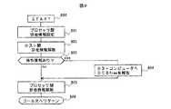
図6は、データアクセス処理部(600)のメインフローである。
まず、ホストコンピュータ300からのデータアクセスコマンドを制御プロセッサ305が、受領すると、指定されたドライブ番号のDCBに対するアクセス権を確保するDCB処理を行う(601)。
DCB確保が成功したか否かの判定をする(602)。失敗すれば、データアクセス処理を終了する(616)。成功すれば、以下の処理を行う。
まず、キャッシュスロット確保処理を行う(603)。次いで、データアクセスコマンドがライトコマンドかリードコマンドかを判定する(604)。
【0015】
ライトコマンドであれば、以下の処理を実行する。
【0016】
制御プロセッサに接続されているホストコンピュータインタフェースがCKDフォーマットかFBAフォーマットかをホストコンピュータインタフェース管理情報テーブル500(図5)を参照し(610)、判定する(611)。
本実施例の場合、制御プロセッサ305は、CKDフォーマット506、制御プロセッサ306は、FBAフォーマット507である。
CKDフォーマットであれば、CKDデータをFBAデータに変換し(612)、その後、キャッシュスロット312へ変換されたライトデータを書き込み(613)、FBAフォーマットであれば、FBAデータをそのままキャッシュスロット312へ書き込む。
その後、キャッシュスロットを解放し(614)、DCBを解放する(615)。
【0017】
受領コマンドが、リードコマンドであれば、以下の処理を実行する。
まず、キャッシュメモリに読み出しデータが有るか判定する(617)。
データが有れば、(605)以下の処理を行い、データが無ければ、▲1▼の処理を行う。
▲1▼の処理は、制御プロセッサ305、306がドライブからのデータの読み出しを制御プロセッサ310、311に指示し、制御プロセッサ310、311がドライブインタフェース313、314を介してドライブからデータを読み出し、キャッシュメモリのキャッシュスロットに書き込む処理である。なお、この処理は図6のフローチャートでは省略している。
【0018】
次に、(605)以下の処理を説明する。
まず、キャッシュスロット312上のデータを読み出す(605)。
次いで、制御プロセッサ305、306に接続されているホストコンピュータインタフェースがCKDフォーマットかFBAフォーマットかをホストコンピュータインタフェース管理情報テーブル500(図5)を参照し(606)、判定する(607)。
CKDフォーマットであれば、読み出したデータをFBAデータをCKDデータに変換し(608)、ホストコンピュータ300へデータ転送する(609)。
FBAフォーマットであれば、キャッシュスロット312から読み出したデータをそのままホストコンピュータ303へデータ転送する。
続いて、キャッシュスロット312を解放し(614)、DCBを解放する(615)。
なお、キャッシュスロット312上のライトデータは、制御プロセッサ310、311が、ホストコンピュータ300、303の動作とは、非同期に、ドライブ315、316へ書き込む。すなわち、制御プロセッサ310、311が、キャッシュメモリを探索し、キャッシュスロットにドライブに書き込むべきデータがあるとき、そのデータをドライブに書き込む。
【0019】
図7は、図6におけるDCB確保処理(601)の処理フロー(700)である。まず、指定されたドライブ番号401に対応するDCB400のプロセッサ間排他情報402を設定する(701)。次にホスト間排他情報403が‘on’か否か判定する(702)。‘on’でなければ、ホスト間排他情報403を‘on’に設定し(703)、リターンコードに確保成功を設定する(704)。続いて、プロセッサ間排他情報402を解除し(708)、DCB確保処理(700)を終了する(709)。既に‘on’であれば、以下の処理を行なう。ホストコンピュータにDCB使用中を報告する(705)。次に、DCB400のDCB空き待ち情報404へDCB使用中を報告したホストコンピュータを記録する(706)。リターンコードに確保失敗を設定し(707)、その後、プロセッサ間排他情報402を解除する(708)。
【0020】
図8は、図6におけるDCB解放処理(615)の処理フロー(800)である。
まず、解放要求のあるドライブ番号401のDCB400のプロセッサ間排他情報402を設定する(801)。
次に、ホスト間排他情報403を解除する(802)。
次に、DCB400の空き待ち情報404に登録されているホストコンピュータがあるか否か判定する(803)。
無ければ、プロセッサ間排他情報402を解除し(805)、ドライブ解放処理(800)を終了する(806)。
有れば、登録されているホストコンピュータへDCBが空いたことを報告する(804)。
これにより、片方のホストコンピュータに偏ってDCBが使用されることを防ぐことができる。その後、プロセッサ間排他情報を解除する(805)。
【0021】
上記に説明した実施例において、記憶媒体として磁気ディスク装置を用いたが、磁気ディスク装置の代わりに、磁気テープ装置やフロッピーディスク装置を用いても上記に説明したデータアクセス処理を実現することができる。
【0022】
また、ホストコンピュータは、ホストコンピュータの入出力要求を処理する制御プロセッサ、および、記憶媒体への入出力を処理する制御プロセッサ単位に、記憶制御装置への増設、および、記憶制御装置から減設が可能である。
【0023】
【発明の効果】
以上の実施例に示したように、本発明によれば、記憶制御装置が、異なる各種ホストコンピュータ入出力インタフェイスを有するホストコンピュータ間で、記憶媒体上のデータを共有することが可能となり、ファイルサブシステムの拡張性やデータの即時性が高まる。
また、一台の記憶制御装置で異なる各種ホストコンピュータ入出力インタフェイスを有するホストコンピュータや該ホストコンピュータの入出力データを記憶する各種記憶媒体が接続可能となるため、幅広いコンピュータシステム構成が構築可能となる。
【図面の簡単な説明】
【図1】本発明の原理を示すコンピュータシステムの構成図である。
【図2】本発明の概要を説明するための図である。
【図3】本発明の一実施例のディスクサブシステムの構成図である。
【図4】ドライブ制御ブロックの構成図である。
【図5】ホストコンピュータインタフェース管理情報の1例を示す図である。
【図6】データアクセス処理のフローチャートを示す図である。
【図7】DCB確保処理のフローチャートを示す図である。
【図8】DCB解放処理のフローチャートを示す図である。
【符号の説明】
100〜102、300、303 ホストコンピュータ
103 記憶制御装置
104〜106、108〜110、305〜306、310〜311 制御プロセッサ
111 磁気ディスク装置
112 磁気テープ装置
113 フロッピーディスク装置
107、308 信号線
301 チャネル装置
304 SCSIバス制御装置
307 共通制御メモリ
318 ドライブ制御ブロック(DCB)
309 キャッシュメモリ
312 キャッシュスロット
313〜314 ドライブインタフェース
315〜316 ドライブ
317 サービスプロセッサ[0001]
BACKGROUND OF THE INVENTION
The present invention relates to a subsystem capable of sharing data on various storage media for storing input / output data of the host computer between host computers having different host computer input / output interfaces.
[0002]
[Prior art]
Cases in which mainframes and open system-based department systems are linked, such as downsizing some of the work that has been processed on the mainframe in recent years to department servers (for example, UNIX servers) or incorporating information systems into departments. Is increasing.
In such a case, the difference in the host computer input / output interface between the mainframe data format (CKD format) and the UNIX server data format (FBA format) may require development of a program for data conversion, or between host computers. Therefore, it is difficult to construct a wide range of computer system configurations, such as requiring data exchange or a dedicated storage control device for each host computer input / output interface.
For example, by adopting a hardware configuration that includes a plurality of computers in one system, one of the methods devised to solve such an influence is not limited by the CPU (Central Processing Unit) architecture. An integrated computer system that can execute various programs is disclosed in Japanese Patent Laid-Open No. 60-254270.
[0003]
[Problems to be solved by the invention]
In the prior art disclosed in Japanese Patent Laid-Open No. 60-254270 described above, CPUs with different architectures have a master-slave relationship. The CPU on the slave side is selected by a hardware switch and the system bus is occupied. In order to execute the input / output operation to the storage medium, other slave CPUs having different architectures are exclusively prevented from using the storage medium at the same time. Therefore, when the selected CPU is used for a long time, there is a disadvantage that a storage medium and a system bus which are resources common to the system are occupied for a long time.
Further, since the files in the magnetic disk device are stored separately for each CPU having a different architecture, it is impossible to share the same file on the magnetic disk device between CPUs having different architectures.
As described above, in the conventional technology, it is possible for host computers having different architectures to share and use a storage medium. However, since the storage media are mutually exclusive between host computers having different architectures, This was one factor that significantly reduced the utilization efficiency of the subsystem. Further, the disadvantage that data sharing is impossible between host computers having different host computer input / output interfaces remains unsolved.
[0004]
An object of the present invention is to provide a host having different host computer input / output interfaces by performing data conversion on data access requests from host computers having different host computer input / output interfaces, if necessary. Data access requests to computer storage media are possible, and data on storage media can be shared between host computers with different host computer input / output interfaces, improving file subsystem scalability and data immediacy. And providing a subsystem capable of constructing a wide range of computer system configurations.
Another object of the present invention is to add various host computer input / output interfaces and various storage medium input / output interfaces to the subsystem, and various host computer input / output interfaces and various storage medium input / output from the subsystem. It is to provide a subsystem that can be reduced by reducing the number of interfaces.
[0005]
[Means for Solving the Problems]
In order to achieve the above object, the present invention provides:
A storage medium for storing data; a table located between the storage medium and the host computer; managing a data format of the host computer and a data format of the storage medium; and the table and the host computer And a control processor for converting data from the host computer into the data format of the storage medium when the data format of the host computer and the data format of the storage medium are different.
Further, it is a subsystem, a storage medium that stores data, a table that is located between the storage medium and the host computer, manages the data format of the host computer and the data format of the storage medium, and the table and the table A subsystem provided between the host computer and a control processor for converting data from the storage medium into the data format of the host computer when the data format of the host computer and the data format of the storage medium are different .
In any one of the subsystems, the table is provided in a shared memory that stores information for managing the storage medium.
In any of the subsystems, the table is set, updated, or released by a service processor.
In addition, the subsystem is a storage medium for storing data, an interface connected to the storage medium for controlling input / output of the data, and data read from the storage medium connected to the interface are temporarily stored. A cache memory, and a control processor connected to the cache memory and connected to the host computer, the data format of the data stored in the cache memory being different from the data format of the host computer Sometimes the data stored in the cache memory is converted into the data format of the host computer and then transferred to the host computer.
[0006]
DETAILED DESCRIPTION OF THE INVENTION
Embodiments of the present invention will be described below in detail with reference to the drawings.
FIG. 1 is an explanatory diagram showing the operation principle of the present invention. A plurality of host computers having various types of host computer input / output, a storage control device for controlling input / output from the host computer, and an input of the host computer. It is a block diagram of the computer system comprised from the various storage media which memorize | store output data.
In FIG. 1, a plurality of host computers A100, B101, and C102 having various different host computer input / output interfaces are connected via a
The
That is, the
All the
[0007]
FIG. 2 is a diagram for explaining the outline of the present invention. The outline of the present invention will be described below with reference to FIG.
In FIG. 2, host computers A 200 and
Access requests 204 (write), 205 (read), 206 (write), and 207 (read) to the
When the
When the
The processing for the access request from the host computer B201 is performed in the same manner as the processing for the access request from the host computer A200.
As described above, data on the storage medium can be shared between host computers having various different host computer input / output interfaces.
[0008]
FIG. 3 is a block diagram of a disk subsystem with a cache memory showing an embodiment of the present invention.
In FIG. 3, the
In this embodiment, the
On the lower side, it is connected to
[0009]
The
The
The
[0010]
The
The
The
[0011]
The
When the
[0012]
Next, the common control information will be described.
The common control information includes a
FIG. 4 shows a drive control block (Device Control Block; DCB for short) 400. There are as
These are four data, a
The
The host-to-
The drive
[0013]
FIG. 5 shows the host interface management information table 500.
The connected
In this embodiment, the control processor 305 (503 in FIG. 5) manages the
[0014]
Next, the operation of the
FIG. 6 is a main flow of the data access processing unit (600).
First, when the
It is determined whether the DCB reservation is successful (602). If it fails, the data access process is terminated (616). If successful, the following processing is performed.
First, a cache slot securing process is performed (603). Next, it is determined whether the data access command is a write command or a read command (604).
[0015]
If it is a write command, the following processing is executed.
[0016]
Whether the host computer interface connected to the control processor is CKD format or FBA format is determined by referring to the host computer interface management information table 500 (FIG. 5) (610) (611).
In this embodiment, the
If it is the CKD format, the CKD data is converted to FBA data (612), and then the converted write data is written to the cache slot 312 (613). If it is the FBA format, the FBA data is directly written to the cache slot 312. .
Thereafter, the cache slot is released (614), and the DCB is released (615).
[0017]
If the received command is a read command, the following processing is executed.
First, it is determined whether there is read data in the cache memory (617).
If there is data, the process from (605) onward is performed, and if there is no data, the process (1) is performed.
In the process (1), the
[0018]
Next, (605) the following processing will be described.
First, the data on the cache slot 312 is read (605).
Next, whether the host computer interface connected to the
If the format is the CKD format, the read data is converted from FBA data to CKD data (608), and the data is transferred to the host computer 300 (609).
In the FBA format, the data read from the cache slot 312 is transferred to the
Subsequently, the cache slot 312 is released (614), and the DCB is released (615).
The write data on the cache slot 312 is written to the
[0019]
FIG. 7 is a processing flow (700) of the DCB reservation processing (601) in FIG. First, the
[0020]
FIG. 8 is a processing flow (800) of the DCB release processing (615) in FIG.
First, the
Next, the host
Next, it is determined whether there is a host computer registered in the
If not, the
If there is, it is reported to the registered host computer that the DCB is free (804).
As a result, it is possible to prevent the DCB from being used biased to one host computer. Thereafter, the inter-processor exclusive information is canceled (805).
[0021]
In the embodiment described above, the magnetic disk device is used as the storage medium. However, the data access processing described above can be realized even if a magnetic tape device or a floppy disk device is used instead of the magnetic disk device. .
[0022]
In addition, the host computer can be added to and removed from the storage control device in units of control processors that process input / output requests of the host computer and control processors that process input / output to the storage medium. Is possible.
[0023]
【The invention's effect】
As shown in the above embodiments, according to the present invention, the storage control device can share data on a storage medium between host computers having different host computer input / output interfaces, and a file Increases subsystem scalability and data immediacy.
In addition, it is possible to connect a host computer having various host computer input / output interfaces and various storage media for storing the input / output data of the host computer in a single storage control device, so that a wide range of computer system configurations can be constructed. Become.
[Brief description of the drawings]
FIG. 1 is a configuration diagram of a computer system showing the principle of the present invention.
FIG. 2 is a diagram for explaining the outline of the present invention.
FIG. 3 is a configuration diagram of a disk subsystem according to an embodiment of the present invention.
FIG. 4 is a configuration diagram of a drive control block.
FIG. 5 is a diagram showing an example of host computer interface management information.
FIG. 6 is a flowchart of data access processing.
FIG. 7 is a diagram illustrating a flowchart of a DCB securing process.
FIG. 8 is a diagram illustrating a flowchart of DCB release processing.
[Explanation of symbols]
100 to 102, 300, 303
309 Cache memory 312
Claims (3)
Translated fromJapanese前記記憶制御装置は、前記複数のホストコンピュータからのデータの書込み要求を受領した場合に、前記異なるアーキテクチャーのうちの1のフォーマット形式で前記記憶媒体にデータを記憶し、前記ホストコンピュータがアクセスしようとするディスクドライブへのアクセスが排他されているかどうかを判定するためのホスト間排他情報を含む複数のドライブ制御情報と、前記複数のホストコンピュータのインタフェース情報が記録されるホストコンピュータインタフェース管理テーブルを有し、
前記複数のホストコンピュータのうちの1のホストコンピュータからアクセス要求を受けた前記制御プロセッサは、前記ドライブ制御情報を参照して、アクセスしようとするディスクドライブへのアクセスが他のホストコンピュータによって排他状態にあるかどうかを判定し、
排他されていない場合に、前記ホストコンピュータインタフェース管理テーブルを参照してそのホストコンピュータのインタフェースが前記1のフォーマット形式と異なることからデータの変換を必要とするものであるかどうかを判定し、前記1のフォーマット形式と異なるために変更が必要なものであると判定された場合には、前記データを変換して前記ホストコンピュータからのアクセス要求に応答し、変換が不要と判定された場合には前記データを変更することなく前記ホストコンピュータからのアクセス要求に応答することを特徴とする記憶システム。A storage medium comprising a plurality of disk drives for storing data; a cache memory for temporarily storing data read from the storage medium connected to the storage medium; and a cache memory connected to the cache memory and having anarchitecture A storage system having a storage control device having a plurality of control processors arranged for a plurality ofdifferent host computers,
When the storage controllerreceives a data write request from the plurality of host computers , the storage controller storesthe data in the storage medium in one format of the different architectures, and the host computer tries to access thestorage medium . Aplurality of drive control information including exclusion information between hosts for determining whether or not access to the disk drive to be excluded is exclusive, and a host computer interface management table in which interface information of the plurality of host computers is recorded. And
The control processor that has received an access request fromone of the plurality of host computers refers to the drive control information, and access to the disk drive to be accessed is made exclusive by another host computer. Determine if there is,
If not exclusively, with reference to the host computer interface management table to determine whether the host computer interface is intended to require conversion of datasince different from the format of the 1,wherein the 1 If it is determined that the data needs to be changedbecause it is different from the format format , the data is converted to respond to an access request from the host computer, and if it is determined that conversion is not necessary, A storage system that responds to an access request from the host computer without changing data.
前記ドライブ制御情報は、前記制御プロセッサがアクセスしようとするディスクドライブへのアクセスが排他されているかどうかを判定するための制御プロセッサ間排他情報を含み、
前記ホストコンピュータからアクセス要求を受けた前記制御プロセッサは、前記ドライブ制御情報を参照して、アクセスしようとするディスクドライブへのアクセスが他の制御プロセッサによって排他状態にあるかどうかを判定し、
排他されていない場合に、アクセスしようとするディスクドライブへのアクセスが他のホストコンピュータによって排他状態にあるかどうかの判定を行うことを特徴とする記憶システム。The storage system of claim 1, wherein
The drive control information includes exclusive control information between control processors for determining whether access to a disk drive to be accessed by the control processor is exclusive,
The control processor that has received an access request from the host computer refers to the drive control information to determine whether access to the disk drive to be accessed is in an exclusive state by another control processor;
A storage system for determining whether or not access to a disk drive to be accessed is in an exclusive state by another host computer when it is not exclusive.
前記記憶制御装置にサービスプロセッサを接続し、
該サービスプロセッサにより選択された前記制御プロセッサが、前記ホストコンピュータインタフェース管理テーブルを該サービスプロセッサから転送される修正情報により修正することを特徴とする記憶システム。The storage system of claim 1, wherein
Connecting a service processor to the storage controller;
The storage system, wherein the control processor selected by the service processor modifies the host computer interface management table with modification information transferred from the service processor.
Priority Applications (5)
| Application Number | Priority Date | Filing Date | Title |
|---|---|---|---|
| JP16392796AJP3781212B2 (en) | 1996-06-04 | 1996-06-04 | sub-system |
| DE69728212TDE69728212T2 (en) | 1996-06-04 | 1997-06-02 | Memory control and computer system using it |
| US08/867,191US5920893A (en) | 1996-06-04 | 1997-06-02 | Storage control and computer system using the same |
| EP03027725AEP1403757A3 (en) | 1996-06-04 | 1997-06-02 | Method of controlling data transfer |
| EP97108823AEP0811905B1 (en) | 1996-06-04 | 1997-06-02 | Storage control and computer system using the same |
Applications Claiming Priority (1)
| Application Number | Priority Date | Filing Date | Title |
|---|---|---|---|
| JP16392796AJP3781212B2 (en) | 1996-06-04 | 1996-06-04 | sub-system |
Related Child Applications (1)
| Application Number | Title | Priority Date | Filing Date |
|---|---|---|---|
| JP04281099ADivisionJP3778405B2 (en) | 1999-02-22 | 1999-02-22 | Disk subsystem |
Publications (2)
| Publication Number | Publication Date |
|---|---|
| JPH09325905A JPH09325905A (en) | 1997-12-16 |
| JP3781212B2true JP3781212B2 (en) | 2006-05-31 |
Family
ID=15783476
Family Applications (1)
| Application Number | Title | Priority Date | Filing Date |
|---|---|---|---|
| JP16392796AExpired - Fee RelatedJP3781212B2 (en) | 1996-06-04 | 1996-06-04 | sub-system |
Country Status (4)
| Country | Link |
|---|---|
| US (1) | US5920893A (en) |
| EP (2) | EP0811905B1 (en) |
| JP (1) | JP3781212B2 (en) |
| DE (1) | DE69728212T2 (en) |
Families Citing this family (60)
| Publication number | Priority date | Publication date | Assignee | Title |
|---|---|---|---|---|
| JP3264465B2 (en)* | 1993-06-30 | 2002-03-11 | 株式会社日立製作所 | Storage system |
| EP0785500B1 (en) | 1996-01-19 | 2004-03-03 | Hitachi, Ltd. | Storage device and method for data sharing |
| JPH09204403A (en)* | 1996-01-26 | 1997-08-05 | Hitachi Ltd | Parallel computer |
| US6735676B1 (en)* | 1996-09-02 | 2004-05-11 | Hitachi, Ltd. | Method and system for sharing storing device via mutually different interfaces |
| US6304940B1 (en)* | 1997-08-14 | 2001-10-16 | International Business Machines Corporation | Shared direct access storage system for MVS and FBA processors |
| JP3407628B2 (en)* | 1997-12-19 | 2003-05-19 | 株式会社日立製作所 | Computer system |
| US6260040B1 (en)* | 1998-01-05 | 2001-07-10 | International Business Machines Corporation | Shared file system for digital content |
| US6173360B1 (en)* | 1998-01-09 | 2001-01-09 | International Business Machines Corporation | Apparatus and method for allowing existing ECKD MVS DASD using an ESCON interface to be used by an open storage using SCSI-type interface |
| US6041386A (en)* | 1998-02-10 | 2000-03-21 | International Business Machines Corporation | Data sharing between system using different data storage formats |
| JP3404289B2 (en)* | 1998-05-22 | 2003-05-06 | 富士通株式会社 | Disk control device and control method thereof |
| US6195703B1 (en)* | 1998-06-24 | 2001-02-27 | Emc Corporation | Dynamic routing for performance partitioning in a data processing network |
| US6438595B1 (en)* | 1998-06-24 | 2002-08-20 | Emc Corporation | Load balancing using directory services in a data processing system |
| US6421711B1 (en) | 1998-06-29 | 2002-07-16 | Emc Corporation | Virtual ports for data transferring of a data storage system |
| JP2000029635A (en)* | 1998-07-08 | 2000-01-28 | Hitachi Ltd | Storage controller |
| JP2000047972A (en)* | 1998-07-29 | 2000-02-18 | Hitachi Ltd | I / O control method |
| JP4392877B2 (en) | 1998-09-18 | 2010-01-06 | 株式会社日立製作所 | Disk array controller |
| JP2000163246A (en)* | 1998-11-25 | 2000-06-16 | Hitachi Ltd | Storage subsystem with FIFO function |
| US6389494B1 (en)* | 1998-12-30 | 2002-05-14 | Emc Corporation | System for interfacing a data storage system to a host utilizing a plurality of busses for carrying end-user data and a separate bus for carrying interface state data |
| US7073020B1 (en) | 1999-01-04 | 2006-07-04 | Emc Corporation | Method for message transfer in computer storage system |
| US7117275B1 (en) | 1999-01-04 | 2006-10-03 | Emc Corporation | Data storage system having separate data transfer section and message network |
| JP3700438B2 (en)* | 1999-01-06 | 2005-09-28 | 株式会社日立製作所 | Computer system |
| JP4400895B2 (en)* | 1999-01-07 | 2010-01-20 | 株式会社日立製作所 | Disk array controller |
| US6272533B1 (en)* | 1999-02-16 | 2001-08-07 | Hendrik A. Browne | Secure computer system and method of providing secure access to a computer system including a stand alone switch operable to inhibit data corruption on a storage device |
| US6615327B1 (en)* | 1999-02-19 | 2003-09-02 | Hitachi, Ltd. | Method and system for backing up data of data processing devices including fixed length block format data conversion to variable length block format |
| JP3778405B2 (en)* | 1999-02-22 | 2006-05-24 | 株式会社日立製作所 | Disk subsystem |
| JP2001022715A (en)* | 1999-07-13 | 2001-01-26 | Hitachi Ltd | Data format conversion mechanism and conversion method under multi-platform environment |
| US7353240B1 (en) | 1999-09-29 | 2008-04-01 | Hitachi, Ltd. | Method and storage system that enable sharing files among multiple servers |
| JP2001142754A (en)* | 1999-11-15 | 2001-05-25 | Nec Fielding Ltd | File editing system for flexible disk |
| US6735765B1 (en)* | 1999-12-07 | 2004-05-11 | Storage Technology Corporation | Sharing data between operating systems |
| US7003601B1 (en) | 2000-03-31 | 2006-02-21 | Emc Corporation | Data storage system having separate data transfer section and message network with plural directions on a common printed circuit board |
| US7010575B1 (en)* | 2000-03-31 | 2006-03-07 | Emc Corporation | Data storage system having separate data transfer section and message network having bus arbitration |
| US7007194B1 (en) | 2000-06-29 | 2006-02-28 | Emc Corporation | Data storage system having point-to-point configuration |
| US6877061B2 (en)* | 2000-03-31 | 2005-04-05 | Emc Corporation | Data storage system having dummy printed circuit boards |
| US6779071B1 (en) | 2000-04-28 | 2004-08-17 | Emc Corporation | Data storage system having separate data transfer section and message network with status register |
| JP3753598B2 (en)* | 2000-07-06 | 2006-03-08 | 株式会社日立製作所 | Computer, computer system and data transfer method |
| JP2002108567A (en) | 2000-09-28 | 2002-04-12 | Hitachi Ltd | Storage controller |
| JP2002203057A (en)* | 2000-11-01 | 2002-07-19 | Cec:Kk | Value-added data warehouse system |
| US6718410B2 (en)* | 2001-01-18 | 2004-04-06 | Hewlett-Packard Development Company, L.C. | System for transferring data in a CD image format size of a host computer and storing the data to a tape medium in a format compatible with streaming |
| US6779063B2 (en) | 2001-04-09 | 2004-08-17 | Hitachi, Ltd. | Direct access storage system having plural interfaces which permit receipt of block and file I/O requests |
| AU2002315565B2 (en)* | 2001-06-29 | 2007-05-24 | Secure Systems Limited | Security system and method for computers |
| US7281044B2 (en)* | 2002-01-10 | 2007-10-09 | Hitachi, Ltd. | SAN infrastructure on demand service system |
| US6907483B1 (en)* | 2002-03-28 | 2005-06-14 | Emc Corporation | Data storage system having dummy printed circuit boards with jumpers |
| US6868479B1 (en)* | 2002-03-28 | 2005-03-15 | Emc Corporation | Data storage system having redundant service processors |
| JP4008752B2 (en)* | 2002-05-22 | 2007-11-14 | 株式会社日立製作所 | Storage device system control method and storage device system |
| US7117305B1 (en) | 2002-06-26 | 2006-10-03 | Emc Corporation | Data storage system having cache memory manager |
| US7206989B2 (en) | 2002-11-20 | 2007-04-17 | Intel Corporation | Integrated circuit having multiple modes of operation |
| US7543085B2 (en)* | 2002-11-20 | 2009-06-02 | Intel Corporation | Integrated circuit having multiple modes of operation |
| JP2004185544A (en)* | 2002-12-06 | 2004-07-02 | Hitachi Ltd | Method of controlling storage device control device system and storage device control device system |
| JP4322031B2 (en)* | 2003-03-27 | 2009-08-26 | 株式会社日立製作所 | Storage device |
| JP4100256B2 (en)* | 2003-05-29 | 2008-06-11 | 株式会社日立製作所 | Communication method and information processing apparatus |
| JP4401788B2 (en)* | 2004-01-06 | 2010-01-20 | 株式会社日立製作所 | Storage controller |
| JP4727190B2 (en) | 2004-09-07 | 2011-07-20 | 株式会社日立製作所 | Storage device system |
| JP4606823B2 (en)* | 2004-09-14 | 2011-01-05 | 株式会社日立製作所 | Disk array device |
| US8145870B2 (en)* | 2004-12-07 | 2012-03-27 | International Business Machines Corporation | System, method and computer program product for application-level cache-mapping awareness and reallocation |
| US7783833B2 (en)* | 2006-09-28 | 2010-08-24 | Hitachi, Ltd. | Storage system, method for managing the same, and storage controller |
| JP2008084094A (en)* | 2006-09-28 | 2008-04-10 | Hitachi Ltd | Storage system, management method thereof, and storage control device |
| US9282083B2 (en)* | 2009-10-06 | 2016-03-08 | Hewlett-Packard Development Company, L.P. | Encryption system and method |
| US9934244B2 (en) | 2010-08-13 | 2018-04-03 | At&T Intellectual Property I, L.P. | System and method for file format management |
| JP2012203687A (en)* | 2011-03-25 | 2012-10-22 | Nec Corp | Communication device, communication method, and program |
| US20240411694A1 (en)* | 2023-06-06 | 2024-12-12 | Dell Products L.P. | Purposed data transfer using multiple cache slots |
Family Cites Families (10)
| Publication number | Priority date | Publication date | Assignee | Title |
|---|---|---|---|---|
| JPS60254270A (en)* | 1984-05-30 | 1985-12-14 | Toshiba Corp | integrated computer system |
| JP2585569B2 (en)* | 1987-02-27 | 1997-02-26 | 株式会社日立製作所 | Direct memory access controller |
| JPH01309117A (en)* | 1988-06-07 | 1989-12-13 | Nec Eng Ltd | Magnetic disk device |
| JP2897960B2 (en)* | 1989-05-12 | 1999-05-31 | 株式会社リコー | Suction device for sheet members, etc., suction method for sheet members, etc., image recording device, and document handling device |
| JPH03265945A (en)* | 1990-03-15 | 1991-11-27 | Nec Corp | Data sharing system for operating systems of different types |
| US5206939A (en)* | 1990-09-24 | 1993-04-27 | Emc Corporation | System and method for disk mapping and data retrieval |
| US5544347A (en)* | 1990-09-24 | 1996-08-06 | Emc Corporation | Data storage system controlled remote data mirroring with respectively maintained data indices |
| JP3136036B2 (en)* | 1993-11-16 | 2001-02-19 | 富士通株式会社 | Control method of disk controller |
| JP2557203B2 (en)* | 1993-12-27 | 1996-11-27 | インターナショナル・ビジネス・マシーンズ・コーポレイション | Fuzzy packing method and data storage system |
| JP3042341B2 (en)* | 1994-11-30 | 2000-05-15 | 日本電気株式会社 | Local I/O control method for a cluster-connected multiprocessor system |
- 1996
- 1996-06-04JPJP16392796Apatent/JP3781212B2/ennot_activeExpired - Fee Related
- 1997
- 1997-06-02USUS08/867,191patent/US5920893A/ennot_activeExpired - Lifetime
- 1997-06-02EPEP97108823Apatent/EP0811905B1/ennot_activeExpired - Lifetime
- 1997-06-02DEDE69728212Tpatent/DE69728212T2/ennot_activeExpired - Lifetime
- 1997-06-02EPEP03027725Apatent/EP1403757A3/ennot_activeWithdrawn
Also Published As
| Publication number | Publication date |
|---|---|
| EP1403757A2 (en) | 2004-03-31 |
| DE69728212D1 (en) | 2004-04-29 |
| EP1403757A3 (en) | 2004-09-29 |
| DE69728212T2 (en) | 2004-12-02 |
| JPH09325905A (en) | 1997-12-16 |
| EP0811905B1 (en) | 2004-03-24 |
| US5920893A (en) | 1999-07-06 |
| EP0811905A1 (en) | 1997-12-10 |
Similar Documents
| Publication | Publication Date | Title |
|---|---|---|
| JP3781212B2 (en) | sub-system | |
| JP3364572B2 (en) | Data processing system having multipath I/O request mechanism and queue status update method - Patents.com | |
| JP3209634B2 (en) | Computer system | |
| JP3431972B2 (en) | Virtual disk system | |
| EP0869438B1 (en) | Heterogeneous computer system, heterogeneous input/output system and data back-up method for the systems | |
| US6272571B1 (en) | System for improving the performance of a disk storage device by reconfiguring a logical volume of data in response to the type of operations being performed | |
| JP3944449B2 (en) | Computer system, magnetic disk device, and disk cache control method | |
| JP4464378B2 (en) | Computer system, storage system and control method for saving storage area by collecting the same data | |
| US20040162958A1 (en) | Automated on-line capacity expansion method for storage device | |
| US6961818B1 (en) | Method, system and computer program product for managing data in a mirrored cache using an access balancing technique | |
| US20050216663A1 (en) | Storage system | |
| JP2005258918A (en) | Storage system and storage system cache memory control method | |
| JP2003140837A (en) | Disk array controller | |
| JP2002117002A (en) | Common type peripheral architecture | |
| JP2003015826A (en) | Shared memory copy function in disk array controller | |
| JP2000187608A (en) | Storage subsystem | |
| JPS62119626A (en) | Multiple control method for magnetic disks | |
| EP2466446A1 (en) | Storage system, method, and program, comprising a plurality of storage devices | |
| JP3778405B2 (en) | Disk subsystem | |
| JPH1074129A (en) | Disk array device | |
| JP3425355B2 (en) | Multiple write storage | |
| JP2005316697A (en) | Disk array system and method for data backup | |
| JP2004164171A (en) | Path redundancy device and method | |
| JPH0830402A (en) | Parity storage method | |
| JP2755103B2 (en) | Storage device access method |
Legal Events
| Date | Code | Title | Description |
|---|---|---|---|
| RD04 | Notification of resignation of power of attorney | Free format text:JAPANESE INTERMEDIATE CODE: A7424 Effective date:20040316 | |
| A61 | First payment of annual fees (during grant procedure) | Free format text:JAPANESE INTERMEDIATE CODE: A61 Effective date:20060302 | |
| R150 | Certificate of patent or registration of utility model | Free format text:JAPANESE INTERMEDIATE CODE: R150 | |
| FPAY | Renewal fee payment (event date is renewal date of database) | Free format text:PAYMENT UNTIL: 20090317 Year of fee payment:3 | |
| FPAY | Renewal fee payment (event date is renewal date of database) | Free format text:PAYMENT UNTIL: 20100317 Year of fee payment:4 | |
| FPAY | Renewal fee payment (event date is renewal date of database) | Free format text:PAYMENT UNTIL: 20110317 Year of fee payment:5 | |
| FPAY | Renewal fee payment (event date is renewal date of database) | Free format text:PAYMENT UNTIL: 20110317 Year of fee payment:5 | |
| FPAY | Renewal fee payment (event date is renewal date of database) | Free format text:PAYMENT UNTIL: 20120317 Year of fee payment:6 | |
| FPAY | Renewal fee payment (event date is renewal date of database) | Free format text:PAYMENT UNTIL: 20130317 Year of fee payment:7 | |
| FPAY | Renewal fee payment (event date is renewal date of database) | Free format text:PAYMENT UNTIL: 20130317 Year of fee payment:7 | |
| FPAY | Renewal fee payment (event date is renewal date of database) | Free format text:PAYMENT UNTIL: 20140317 Year of fee payment:8 | |
| LAPS | Cancellation because of no payment of annual fees |