JP3781016B2 - Electronic camera, photographing direction acquisition method and program - Google Patents
Electronic camera, photographing direction acquisition method and programDownload PDFInfo
- Publication number
- JP3781016B2 JP3781016B2JP2003154200AJP2003154200AJP3781016B2JP 3781016 B2JP3781016 B2JP 3781016B2JP 2003154200 AJP2003154200 AJP 2003154200AJP 2003154200 AJP2003154200 AJP 2003154200AJP 3781016 B2JP3781016 B2JP 3781016B2
- Authority
- JP
- Japan
- Prior art keywords
- detected
- unit
- electronic camera
- rotation state
- photographing
- Prior art date
- Legal status (The legal status is an assumption and is not a legal conclusion. Google has not performed a legal analysis and makes no representation as to the accuracy of the status listed.)
- Expired - Fee Related
Links
Images


Classifications
- H—ELECTRICITY
- H04—ELECTRIC COMMUNICATION TECHNIQUE
- H04N—PICTORIAL COMMUNICATION, e.g. TELEVISION
- H04N1/00—Scanning, transmission or reproduction of documents or the like, e.g. facsimile transmission; Details thereof
- H04N1/32—Circuits or arrangements for control or supervision between transmitter and receiver or between image input and image output device, e.g. between a still-image camera and its memory or between a still-image camera and a printer device
- H04N1/32101—Display, printing, storage or transmission of additional information, e.g. ID code, date and time or title
- H—ELECTRICITY
- H04—ELECTRIC COMMUNICATION TECHNIQUE
- H04N—PICTORIAL COMMUNICATION, e.g. TELEVISION
- H04N23/00—Cameras or camera modules comprising electronic image sensors; Control thereof
- G—PHYSICS
- G03—PHOTOGRAPHY; CINEMATOGRAPHY; ANALOGOUS TECHNIQUES USING WAVES OTHER THAN OPTICAL WAVES; ELECTROGRAPHY; HOLOGRAPHY
- G03B—APPARATUS OR ARRANGEMENTS FOR TAKING PHOTOGRAPHS OR FOR PROJECTING OR VIEWING THEM; APPARATUS OR ARRANGEMENTS EMPLOYING ANALOGOUS TECHNIQUES USING WAVES OTHER THAN OPTICAL WAVES; ACCESSORIES THEREFOR
- G03B17/00—Details of cameras or camera bodies; Accessories therefor
- G03B17/02—Bodies
- G—PHYSICS
- G03—PHOTOGRAPHY; CINEMATOGRAPHY; ANALOGOUS TECHNIQUES USING WAVES OTHER THAN OPTICAL WAVES; ELECTROGRAPHY; HOLOGRAPHY
- G03B—APPARATUS OR ARRANGEMENTS FOR TAKING PHOTOGRAPHS OR FOR PROJECTING OR VIEWING THEM; APPARATUS OR ARRANGEMENTS EMPLOYING ANALOGOUS TECHNIQUES USING WAVES OTHER THAN OPTICAL WAVES; ACCESSORIES THEREFOR
- G03B17/00—Details of cameras or camera bodies; Accessories therefor
- G03B17/18—Signals indicating condition of a camera member or suitability of light
- G03B17/20—Signals indicating condition of a camera member or suitability of light visible in viewfinder
- H—ELECTRICITY
- H04—ELECTRIC COMMUNICATION TECHNIQUE
- H04N—PICTORIAL COMMUNICATION, e.g. TELEVISION
- H04N1/00—Scanning, transmission or reproduction of documents or the like, e.g. facsimile transmission; Details thereof
- H04N1/00127—Connection or combination of a still picture apparatus with another apparatus, e.g. for storage, processing or transmission of still picture signals or of information associated with a still picture
- H04N1/00323—Connection or combination of a still picture apparatus with another apparatus, e.g. for storage, processing or transmission of still picture signals or of information associated with a still picture with a measuring, monitoring or signaling apparatus, e.g. for transmitting measured information to a central location
- H—ELECTRICITY
- H04—ELECTRIC COMMUNICATION TECHNIQUE
- H04N—PICTORIAL COMMUNICATION, e.g. TELEVISION
- H04N23/00—Cameras or camera modules comprising electronic image sensors; Control thereof
- H04N23/50—Constructional details
- H04N23/51—Housings
- H—ELECTRICITY
- H04—ELECTRIC COMMUNICATION TECHNIQUE
- H04N—PICTORIAL COMMUNICATION, e.g. TELEVISION
- H04N23/00—Cameras or camera modules comprising electronic image sensors; Control thereof
- H04N23/50—Constructional details
- H04N23/54—Mounting of pick-up tubes, electronic image sensors, deviation or focusing coils
- H—ELECTRICITY
- H04—ELECTRIC COMMUNICATION TECHNIQUE
- H04N—PICTORIAL COMMUNICATION, e.g. TELEVISION
- H04N23/00—Cameras or camera modules comprising electronic image sensors; Control thereof
- H04N23/58—Means for changing the camera field of view without moving the camera body, e.g. nutating or panning of optics or image sensors
- H—ELECTRICITY
- H04—ELECTRIC COMMUNICATION TECHNIQUE
- H04N—PICTORIAL COMMUNICATION, e.g. TELEVISION
- H04N23/00—Cameras or camera modules comprising electronic image sensors; Control thereof
- H04N23/60—Control of cameras or camera modules
- H04N23/63—Control of cameras or camera modules by using electronic viewfinders
- H04N23/633—Control of cameras or camera modules by using electronic viewfinders for displaying additional information relating to control or operation of the camera
- H—ELECTRICITY
- H04—ELECTRIC COMMUNICATION TECHNIQUE
- H04N—PICTORIAL COMMUNICATION, e.g. TELEVISION
- H04N1/00—Scanning, transmission or reproduction of documents or the like, e.g. facsimile transmission; Details thereof
- H04N1/00127—Connection or combination of a still picture apparatus with another apparatus, e.g. for storage, processing or transmission of still picture signals or of information associated with a still picture
- H04N1/00281—Connection or combination of a still picture apparatus with another apparatus, e.g. for storage, processing or transmission of still picture signals or of information associated with a still picture with a telecommunication apparatus, e.g. a switched network of teleprinters for the distribution of text-based information, a selective call terminal
- H04N1/00307—Connection or combination of a still picture apparatus with another apparatus, e.g. for storage, processing or transmission of still picture signals or of information associated with a still picture with a telecommunication apparatus, e.g. a switched network of teleprinters for the distribution of text-based information, a selective call terminal with a mobile telephone apparatus
- H—ELECTRICITY
- H04—ELECTRIC COMMUNICATION TECHNIQUE
- H04N—PICTORIAL COMMUNICATION, e.g. TELEVISION
- H04N2101/00—Still video cameras
- H—ELECTRICITY
- H04—ELECTRIC COMMUNICATION TECHNIQUE
- H04N—PICTORIAL COMMUNICATION, e.g. TELEVISION
- H04N2201/00—Indexing scheme relating to scanning, transmission or reproduction of documents or the like, and to details thereof
- H04N2201/32—Circuits or arrangements for control or supervision between transmitter and receiver or between image input and image output device, e.g. between a still-image camera and its memory or between a still-image camera and a printer device
- H04N2201/3201—Display, printing, storage or transmission of additional information, e.g. ID code, date and time or title
- H04N2201/3204—Display, printing, storage or transmission of additional information, e.g. ID code, date and time or title of data relating to a user, sender, addressee, machine or electronic recording medium
- H—ELECTRICITY
- H04—ELECTRIC COMMUNICATION TECHNIQUE
- H04N—PICTORIAL COMMUNICATION, e.g. TELEVISION
- H04N2201/00—Indexing scheme relating to scanning, transmission or reproduction of documents or the like, and to details thereof
- H04N2201/32—Circuits or arrangements for control or supervision between transmitter and receiver or between image input and image output device, e.g. between a still-image camera and its memory or between a still-image camera and a printer device
- H04N2201/3201—Display, printing, storage or transmission of additional information, e.g. ID code, date and time or title
- H04N2201/3225—Display, printing, storage or transmission of additional information, e.g. ID code, date and time or title of data relating to an image, a page or a document
- H04N2201/3253—Position information, e.g. geographical position at time of capture, GPS data
- H—ELECTRICITY
- H04—ELECTRIC COMMUNICATION TECHNIQUE
- H04N—PICTORIAL COMMUNICATION, e.g. TELEVISION
- H04N2201/00—Indexing scheme relating to scanning, transmission or reproduction of documents or the like, and to details thereof
- H04N2201/32—Circuits or arrangements for control or supervision between transmitter and receiver or between image input and image output device, e.g. between a still-image camera and its memory or between a still-image camera and a printer device
- H04N2201/3201—Display, printing, storage or transmission of additional information, e.g. ID code, date and time or title
- H04N2201/3225—Display, printing, storage or transmission of additional information, e.g. ID code, date and time or title of data relating to an image, a page or a document
- H04N2201/3254—Orientation, e.g. landscape or portrait; Location or order of the image data, e.g. in memory
- H—ELECTRICITY
- H04—ELECTRIC COMMUNICATION TECHNIQUE
- H04N—PICTORIAL COMMUNICATION, e.g. TELEVISION
- H04N2201/00—Indexing scheme relating to scanning, transmission or reproduction of documents or the like, and to details thereof
- H04N2201/32—Circuits or arrangements for control or supervision between transmitter and receiver or between image input and image output device, e.g. between a still-image camera and its memory or between a still-image camera and a printer device
- H04N2201/3201—Display, printing, storage or transmission of additional information, e.g. ID code, date and time or title
- H04N2201/3274—Storage or retrieval of prestored additional information
- H04N2201/3277—The additional information being stored in the same storage device as the image data
Landscapes
- Engineering & Computer Science (AREA)
- Multimedia (AREA)
- Signal Processing (AREA)
- Physics & Mathematics (AREA)
- General Physics & Mathematics (AREA)
- Studio Devices (AREA)
- Indication In Cameras, And Counting Of Exposures (AREA)
- Camera Bodies And Camera Details Or Accessories (AREA)
- Accessories Of Cameras (AREA)
- Details Of Cameras Including Film Mechanisms (AREA)
- Television Signal Processing For Recording (AREA)
Description
Translated fromJapanese【0001】
【発明の属する技術分野】
本発明は、撮像部が本体筐体に対して回動自在に設けられた電子カメラ、撮影方向取得方法及びプログラムに関する。
【0002】
【従来の技術】
近時、銀塩フィルムを使用する銀塩カメラに代わって、撮影により得た画像データをデジタルデータ化してメモリカード等に記録可能なデジタルカメラが一般に普及しつつある。この主のデジタルカメラには、本体筐体に対してレンズ光学系や撮像素子であるCCD等を含んだ撮像部(カメラ部)が回動自在に設けられた機種が少なからずあり、それらの機種では、本体筐体に設けられた液晶モニタで撮像内容を確認しながらローアングルの撮影や、撮影者本人の撮影(自画撮り)を比較的容易に実行可能としている。
【0003】
また、デジタルカメラの一部機種には、方位センサにより取得された方位情報を撮影方位情報として撮影により得られた画像データと関連付けて記録可能なものもある。
【0004】
【発明が解決しようとする課題】
しかしながら、撮像部が本体筐体に対して回動可能なデジタルカメラに上記方位センサを内蔵させようとした場合にいくつかの問題が生じてしまう。
【0005】
つまり、上記方位センサを撮像部内に設けた場合は、撮像部が方位センサを内蔵する分だけ重くなったり、大きくなってしまうので、撮像部を本体筐体に対して回動させる際の使い勝手が悪くなったり、デジタルカメラのデザイン設計上の制約を生じさせてしまう。
【0006】
一方、上記方位センサを本体筐体内に設けた場合は、撮像部の本体筐体に対する回動状態により方位センサで得られる方位と実際の撮影方位とが大きく異なってしまうという問題を生じさせてしまう。
【0007】
本発明は上記のような実情に鑑みてなされたもので、その目的とするところは、撮像部の構成を簡素化すると同時に、撮像部の本体筐体に対する回動状態に関係なく正確な撮影方向を取得することが可能な電子カメラ、撮影方向取得方法及びプログラムを提供することにある。
【0008】
【課題を解決するための手段】
請求項1記載の発明は、本体部に対して回動自在に設けられた、被写体像を撮像する撮像手段と、上記本体部に設けられた、撮影方向を検出する撮影方向検出手段と、上記本体部に対する上記撮像手段の回動状態を検出する回動状態検出手段と、この回動状態検出手段により検出された回動状態に基づき、上記撮影方向検出手段により検出された撮影方向を補正する補正手段とを具備したことを特徴とする。
【0009】
このような構成とすれば、撮像手段の回動角度に基づき撮影方向を補正するようにしたため、正確な撮影方向を得ることができる。
【0010】
請求項2記載の発明は、上記請求項1記載の発明において、上記回動状態検出手段は、上記本体部に対する上記撮像手段の回動角度を検出する手段を含むことを特徴とする。
【0011】
このような構成とすれば、上記請求項1記載の発明の作用に加えて、上記撮像手段の回動角度を検出するようにしたため、より正確な撮影方向を得ることができる。
【0012】
請求項3記載の発明は、上記請求項2記載の発明において、上記補正手段は、上記回動状態検出手段により検出された回動角度と、上記撮影方向検出手段により検出された撮影方向とを加減演算することにより撮影方向を補正する手段を含むことを特徴とする。
【0013】
このような構成とすれば、上記請求項2記載の発明の作用に加えて、上記撮像手段の回動角度を、検出された撮影方向に加減算するようにしたため、より一層正確な撮影方向を得ることができる。
【0014】
請求項4記載の発明は、上記請求項1乃至3のいずれかに記載の発明において、上記撮影方向検出手段は、方位角を検出する手段を含み、上記補正手段は、上記回動状態検出手段により検出された回動状態に基づき、上記撮影方向検出手段により検出された方位角を補正する手段を含むことを特徴とする。
【0015】
このような構成とすれば、上記請求項1乃至3のいずれかに記載の発明の作用に加えて、正確な撮影方位を得ることができる。
【0016】
請求項5記載の発明は、上記請求項1乃至4のいずれかに記載の発明において、上記撮影方向検出手段は、チルト角度を検出する手段を含み、上記補正手段は、上記回動状態検出手段により検出された回動状態に基づき、上記撮影方向検出手段により検出されたチルト角度を補正する手段を含むことを特徴とする。
【0017】
このような構成とすれば、上記請求項1乃至4のいずれかに記載の発明の作用に加えて、撮影角度であるチルト角度を正確に得ることができる。
【0018】
請求項6記載の発明は、上記請求項1乃至5のいずれかに記載の発明において、上記補正手段により補正された撮影方向に基づく情報を記録する記録手段を備えることを特徴とする。
【0019】
このような構成とすれば、上記請求項1乃至5のいずれかに記載の発明の作用に加えて、後に記録した撮影方向に基づく情報を再生して確認することができる。
【0020】
請求項7記載の発明は、上記請求項6記載の発明において、上記記録手段は、上記撮像手段により得られた画像データを記録する手段を含み、上記補正手段により補正された撮影方向に基づく情報を上記画像データに関連付けて上記記録手段に記録させる記録制御手段を備えることを特徴とする。
【0021】
このような構成とすれば、上記請求項6記載の発明の作用に加えて、後に記録した画像データを再生して確認する際に、合わせて撮影方向を確認することができる。
【0022】
請求項8記載の発明は、上記請求項1乃至7のいずれかに記載の発明において、上記補正手段により補正された撮影方向に基づく情報を表示する表示手段を備えることを特徴とする。
【0023】
このような構成とすれば、上記請求項1乃至7のいずれかに記載の発明の作用に加えて、得られた正確な撮影方向をその場で確認することができる。
【0024】
請求項9記載の発明は、上記請求項8記載の発明において、上記表示手段は、上記撮像手段により得られた画像データを表示する手段を含み、上記補正手段により補正された撮影方向に基づく情報を上記画像データとともに上記表示手段に表示させる表示制御手段を備えることを特徴とする。
【0025】
このような構成とすれば、上記請求項8記載の発明の作用に加えて、画像データを確認する際に、合わせて撮影方向を確認することができる。
【0026】
請求項10記載の発明は、上記請求項1乃至9のいずれかに記載の発明において、上記補正手段により補正された撮影方向に基づく情報を送信する送信手段を備えることを特徴とする。
【0027】
このような構成とすれば、上記請求項1乃至9のいずれかに記載の発明の作用に加えて、得られた正確な撮影方向をその場で相手先に送信することができる。
【0028】
請求項11記載の発明は、上記請求項10記載の発明において、上記送信手段は、上記撮像手段により得られた画像データを送信する手段を含み、上記補正手段により補正された撮影方向に基づく情報を上記画像データとともに上記送信手段に送信させる送信制御手段を備えることを特徴とする。
【0029】
このような構成とすれば、上記請求項11記載の発明の作用に加えて、画像データを相手先に送信する際に、合わせて撮影方向を送信することができる。
【0030】
請求項12記載の発明は、上記請求項1乃至11のいずれかに記載の発明において、上記回動状態検出手段により検出された回動状態に基づき、上記撮影方向検出手段により検出された撮影方向を補正する必要があるか否かを判断する判断手段を備え、上記補正手段は、上記判断手段により上記撮影方向を補正する必要があると判断された場合に、上記撮影方向検出手段により検出された撮影方向を補正する手段を含むことを特徴とする。
【0031】
このような構成とすれば、上記請求項1乃至11のいずれかに記載の発明の作用に加えて、補正を必要とする場合にのみ検出された撮影方向に対して補正を行なうことができる。
【0032】
請求項13記載の発明は、上記請求項1乃至12のいずれかに記載の発明において、上記撮像手段は、上記本体部に対して複数の回動軸により回動自在に設けられており、上記回動状態検出手段は、上記複数の回動軸の回動状態を検出する手段を含み、上記補正手段は、上記回動状態検出手段により検出された複数の回動軸の回動状態に基づき、上記撮影方向検出手段により検出された撮影方向を補正する手段を含むことを特徴とする。
【0033】
このような構成とすれば、上記請求項1乃至12のいずれかに記載の発明の作用に加えて、複数の回動軸が設けられている場合であっても正確な撮影方向を得ることができる。
【0034】
請求項14記載の発明は、上記請求項1乃至13のいずれかに記載の発明において、撮影を指示する撮影指示手段を備え、上記撮影方向検出手段は、上記撮影指示手段により撮影が指示された場合に撮影方向を検出する手段を含むことを特徴とする。
【0035】
このような構成とすれば、上記請求項1乃至13のいずれかに記載の発明の作用に加えて、ユーザにより撮影が指示された場合にのみ撮影方向を検出するため、無駄な検出動作を減らすことができる。
【0036】
請求項15記載の発明は、上記請求項1乃至14のいずれかに記載の発明において、被写体像までの距離を取得する距離取得手段と、現在位置を取得する位置取得手段と、上記距離取得手段により取得された被写体像までの距離、上記位置取得手段により取得された現在位置、及び上記補正手段により補正された撮影方向に基づき、被写体像の位置を算出する被写体位置算出手段とを備えたことを特徴とする。
【0037】
このような構成とすれば、上記請求項1乃至14のいずれかに記載の発明の作用に加えて、正確な被写体位置を得ることができる。
【0038】
請求項16記載の発明は、本体部に対して回動自在に設けられた撮像部の回動状態を検出するステップと、上記本体部に設けられた検出部により撮影方向を検出するステップと、上記検出された撮像部の回動状態に基づき、上記検出された撮影方向を補正するステップとを含む。
【0039】
このような方法とすれば、撮像部の回動角度に基づき撮影方向を補正するようにしたため、正確な撮影方向を得ることができる。
【0040】
請求項17記載の発明は、電子カメラに内蔵されたコンピュータが実行するプログラムであって、上記電子カメラの本体部に対して回動自在に設けられた撮像部の回動状態を検出するステップと、上記検出された撮像部の回動状態に基づき、上記本体部に設けられた検出部により検出された撮影方向を補正するステップとをコンピュータに実行させることを特徴とする。
【0041】
このようなプログラム内容とすれば、撮像部の回動角度に基づき撮影方向を補正するようにしたため、正確な撮影方向を得ることができる。
【0042】
【発明の実施の形態】
(第1の実施の形態)
以下本発明をデジタルスチルカメラ(以下「デジタルカメラ」と略称する)に適用した場合の第1の実施の形態について図面を参照して説明する。
【0043】
図1において、1はデジタルカメラであり、デジタルカメラ1は、本体部(本体筐体)2と、この本体部2に回動可能に取り付けられた撮像部(カメラ部)19とに分かれており、撮像部19の前面(図面の裏面側)には後述するレンズ光学系12が装着されている。
【0044】
一方、本体部2には、記録画像やファインダ画像(スルー画像)を確認するための表示部28が取り付けられているほか、キー入力部29として、シャッタボタンを始めとする各種の操作ボタンが適宜の位置に取り付けられている。
【0045】
更に、本体部2には、後述するGPSアンテナ34が上面に取り付けられているとともに、側面に後述するメモリカード31を挿入するためのカードスロットが設けられている。
【0046】
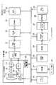
図2は、図1に示したデジタルカメラ1の回路構成を示すものである。
【0047】
このデジタルカメラ1は、基本モードとして撮影モードと再生モードとを切換えて設定可能であり、記録モードでのモニタリング状態においては、モータ11の駆動により合焦位置や絞り位置が移動されるレンズ光学系12の撮影光軸後方に配置された撮像素子であるCCD13が、タイミング発生器(TG)14、垂直ドライバ15によって走査駆動され、一定周期毎に結像した光像に対応する光電変換出力を1画面分出力する。
【0048】
この光電変換出力は、アナログ値の信号の状態でRGBの各原色成分毎に適宜ゲイン調整された後に、サンプルホールド(S/H)回路16でサンプルホールドされ、A/D変換器17でデジタルデータに変換され、カラープロセス回路18へ出力される。
【0049】
しかして、上記モータ11、レンズ光学系12、CCD13、タイミング発生器14、垂直ドライバ15、サンプルホールド回路16、及びA/D変換器17は一つのユニット化した撮像部19として、図1で説明したように、機構的にこのデジタルカメラ1の本体部2に回動自在に設けられる。
【0050】
すなわち撮像部19を、図1に示したように、本体筐体をその正面から見た場合に本体筐体を縦に2分するような鉛直面に沿って手動で回動させることで、本体部2の正面、斜め上方、真上、背面等に任意に対向してその方向にある被写体像を撮影可能とするもので、この撮像部19の本体部2に対する回動角度が、撮像部19の回動軸部に設けられた、例えば光学式ロータリエンコーダ等で構成される回動角度検出部20により検出される。
【0051】
上記カラープロセス回路18は、A/D変換器17から送られてくる画像のデジタルデータに対する画素補間処理及びγ補正処理を含むカラープロセス処理を行ない、デジタル値の輝度信号Y及び色差信号Cb,Crを生成してDMA(Direct Memory Access)コントローラ21に出力する。
【0052】
DMAコントローラ21は、カラープロセス回路18の出力する輝度信号Y及び色差信号Cb,Crを、同じくカラープロセス回路18からの複合同期信号、メモリ書込みイネーブル信号、及びクロック信号を用いて一度DMAコントローラ21内部のバッファに書込み、DRAMインタフェース(I/F)22を介してバッファメモリとして使用されるDRAM23にDMA転送出力する。
【0053】
制御部24は、上記輝度及び色差信号のDRAM23へのDMA転送終了後に、この輝度及び色差信号をDRAMインタフェース22を介してDRAM23より読出し、VRAMコントローラ25を介してVRAM26に書込む。
【0054】
デジタルビデオエンコーダ27は、上記輝度及び色差信号をVRAMコントローラ25を介してVRAM26より定期的に読出し、これらのデータを元にビデオ信号を発生して表示部28に出力する。
【0055】
この表示部28は、例えばバックライト付のカラー液晶表示パネルとその駆動回路とで構成され、図1に示したようにデジタルカメラ1の本体部2の背面側に配設されて、撮影モード時にはモニタ表示部として機能するもので、デジタルビデオエンコーダ27からのビデオ信号に基づいた表示を行なうことで、その時点でVRAMコントローラ25から取込んでいる画像情報に基づく画像を表示することとなる。
【0056】
このように表示部28にその時点での画像がモニタ画像としてリアルタイムに表示されている状態で、静止画撮影を行ないたいタイミングでキー入力部29を構成する複数のキー中のシャッタボタンを操作すると、トリガ信号を発生する。
【0057】
制御部24は、このトリガ信号に応じてその時点でCCD13から取込んでいる1画面分の輝度及び色差信号のDRAM23へのDMA転送の終了後、直ちにCCD13からのDRAM23への経路を停止し、記録保存の状態に遷移する。
【0058】
この記録保存の状態では、制御部24がDRAM23に書込まれている1フレーム分の輝度及び色差信号をDRAMインタフェース22を介してY,Cb,Crの各コンポーネント毎に縦8画素×横8画素の基本ブロックと呼称される単位で読出してJPEG(Joint Photograph coding Experts Group)回路30に書込み、このJPEG回路30でADCT(Adaptive Discrete Cosine Transform:適応離散コサイン変換)、エントロピ符号化方式であるハフマン符号化等の処理によりデータ圧縮する。
【0059】
そして、得た符号データを1画像のデータファイルとして該JPEG回路30から読出し、このデジタルカメラ1の記録媒体として着脱自在に装着される、不揮発性メモリであるフラッシュメモリを封入したメモリカード31に書込む。
【0060】
そして、1フレーム分の輝度及び色差信号の圧縮処理及びメモリカード31への全圧縮データの書込み終了に伴なって、制御部24は再度CCD13からDRAM23への経路を再び起動する。
【0061】
なお、制御部24にはさらに、上述した回動角度検出部20と、GPSレシーバ32及び方位センサ33が接続される。
GPSレシーバ32は、GPSアンテナ34で受信される複数のGPS衛星からの到来電波に基づいて現在位置、すなわち緯度、経度及び高度の各情報と現在時刻とを算出し、上記制御部24へ送出する。
【0062】
方位センサ33は、地磁気を検出する磁気センサとその処理回路(電子コンパス)とでなり、このデジタルカメラ1の本体部2が正対する方向の方位情報を上記制御部24へ出力する。
【0063】
なお、上記キー入力部29は、上述したシャッタボタンの他に、基本モードである撮影(REC)モードと再生(PLAY)モードとを切換えるモード切換えキー、各種メニュー項目を表示させる「メニュー」キー、画像や各種詳細モードの選択、メニュー選択項目の指定等のために上下左右各方向を指示するための十字キー、この十字キーの中央部に配置され、その時点で選択されている内容を指示設定する「セット」キー、上記表示部28での表示をオン/オフするディスプレイキー等から構成され、それらのキー操作に伴なう信号は直接制御部24へ送出される。
【0064】
次に上記実施の形態の動作について説明する。
【0065】
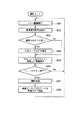
図3は、基本モードとして撮影モードが選択されている状態で制御部24が実行する処理内容を示すものである。
その当初には、CCD13で撮像している画像をそのまま表示部28にて表示するスルー画像表示状態としながら(ステップA01)、回動角度検出部20による撮像部19の本体部2に対する角度情報を検出し(ステップA02)、その検出結果から、撮像部19が表示部28が配設されている本体部2の背面側にまで回動されているか否かを判断する(ステップA03)。
【0066】
ここで、撮像部19が本体部2の背面側にまで回動されていると判断した場合にのみ、方位センサ33で得られる方位情報を補正、具体的には180°反対の方向に書換える処理を実行し(ステップA04)、その上で方位センサ33で得られる方位情報を表示部28でのスルー画像上に重畳表示させながら(ステップA05)、キー入力部29のシャッタボタンが押下げ操作されたか否かを判断し(ステップA06)、操作されなかった場合は上記ステップA01からの処理に戻る。
【0067】
こうしてステップA01〜A06の処理を繰返し実行し、必要により補正した方位情報と共にスルー画像の表示を表示部28で行ないながら、該シャッタボタンが押下げ操作されるのを待機する。
【0068】
そして、ステップA06でシャッタボタンが押下げ操作されたと判断した時点で撮影処理を実行し(ステップA07)、JPEG回路30から得られる画像データを、その時点の適宜必要により補正した方位情報と関連付けてメモリカード31に記録設定して(ステップA08)、その後再び上記ステップA01からの処理に戻る。
【0069】
なお、上記ステップA05でのスルー画像の表示部28への表示に際しては、方位情報のみをスルー画像上に重畳表示するものとして説明したが、実際にはGPSアンテナ34及びGPSレシーバ32で得られるその地点での位置情報(緯度・経度情報)も併せてスルー画像上に重畳表示されるものとする。
【0070】
また、上記ステップA08でのメモリカード31への記録に際しては、画像データに対して方位情報のみを関連付けて記録するものとして説明したが、実際にはGPSアンテナ34及びGPSレシーバ32で得られるその地点での位置情報も併せて関連付けて記録されるものとする。
【0071】
したがって、メモリカード31に記録される画像データは、どの地点からどの方位に向かって撮影されたものであるのか、が正確な情報として付加されることになる。
【0072】
また、上記図3の動作では、シャッタボタンの押下げ操作を待機している状態で、常時方位センサ33から検出される方位情報を必要により補正して表示部28でスルー画像上に重畳表示するものとして説明したが、特にこのデジタルカメラ1のユーザが撮像部19の対向している方位を常時認識している必要がない場合には、必ずしもそのような重畳表示を行なう必要はなく、待機状態での処理をより簡略化することができる。
【0073】
図4は、そのような本実施の形態の変形例に係る撮影モード時の制御部24による処理内容を示すものである。
【0074】
この場合、その処理当初にはCCD13で撮像している画像をそのまま表示部28にて表示するスルー画像表示状態としながら(ステップB01)、キー入力部29のシャッタボタンが押下げ操作されたか否かを判断し(ステップB02)、操作されなかった場合は上記ステップB01からの処理に戻る。
【0075】
こうしてステップB01,B02の処理を繰返し実行し、スルー画像表示を表示部28で行ないながら該シャッタボタンが押下げ操作されるのを待機する。
【0076】
そして、ステップB02でシャッタボタンが押下げ操作されたと判断した時点で撮影処理を実行すると同時に(ステップB03)、回動角度検出部20による撮像部19の本体部2に対する角度情報を検出し(ステップB04)、その検出結果から、撮像部19が表示部28が配設されている本体部2の背面側にまで回動されているか否かを判断する(ステップB05)。
【0077】
ここで撮像部19が本体部2の背面側にまで回動されていると判断した場合にのみ、方位センサ33で得られる方位情報を補正、具体的には180°反対の方向に書換える処理を実行し(ステップB06)、JPEG回路30から得られる画像データを、その時点で適宜必要により補正した方位情報と関連付けてメモリカード31に記録設定して(ステップB07)、その後再び上記ステップB01からの処理に戻る。
【0078】
この場合も、上記ステップB07でのメモリカード31への記録に際しては、画像データに対して、必要により補正を施した方位情報のみを関連付けて記録するものとして説明したが、実際にはGPSアンテナ34及びGPSレシーバ32で得られるその地点での位置情報も併せて関連付けて記録されるものとする。
【0079】
このように、表示部28で必要により補正した方位の情報を重畳表示しないことにより、シャッタボタンの押下げ操作を待機している状態での制御部24の処理負荷を軽減すると共に、回動角度検出部20、方位センサ33の駆動と検出信号の処理頻度を大幅に下げることにより、電源容量に制限のある電池を無駄に消費せずにすむ。
【0080】
なお、上記第1の実施の形態(図3、図4)では、回動角度検出部20が検出した角度情報に基づいて、撮像部19が表示部28が配設されている本体部2の背面側にまで回動されているか否かを判断するようにしたが、回動角度検出部20を設けずに、代わりに撮像部19が表示部28が配設されている本体部2の背面側にまで回動した際にオンする簡易なスイッチ機構を設けるようにして回動状態を検出するようにしてもよい。
【0081】
(第2の実施の形態)
以下本発明をデジタルスチルカメラ(以下「デジタルカメラ」と略称する)に適用した場合の第2の実施の形態について図面を参照して説明する。
【0082】
なお、デジタルカメラ全体の回路構成については基本的に上記図2に示したものと基本的にほぼ同様であるので、同一部分には同一符号を付すものとしてその図示及び説明は省略する。
【0083】
また、撮像部19は、図1に示したものとは異なり、例えば本体部2をその正面から見た場合に水平面に沿って手動で回動することで、例えば本体部2の正面、右方向、背面方向、左方向というように横方向に任意に対向してその方向にある被写体像を撮影可能とするもので、この撮像部19の本体部2に対する回動角度が、撮像部19の回動軸部に設けられた、例えば光学式ロータリエンコーダ等で構成される回動角度検出部20により検出されるものとする。
【0084】
次に上記実施の形態の動作について説明する。
【0085】
図5は、基本モードとして撮影モードが選択されている状態で制御部24が実行する処理内容を示すものである。
その当初には、CCD13で撮像している画像をそのまま表示部28にて表示するスルー画像表示状態としながら(ステップC01)、回動角度検出部20による撮像部19の角度情報を検出し(ステップC02)、その検出結果を方位センサ33の検出する、本体部2が正対している方位情報に加算(又は減算)することで撮像部19が対向している正確な方位を補正演算により取得する(ステップC03)。ここで、撮像部19のレンズ面と本体部2の正面とが同一方向を向いている場合、回動角度検出部20により検出される角度情報は、0°となるものとする。
【0086】
そして、この算出した撮像部19の対向している方位情報を表示部28でのスルー画像上に重畳表示させながら(ステップC04)、キー入力部29のシャッタボタンが押下げ操作されたか否かを判断し(ステップC05)、操作されなかった場合は上記ステップC01からの処理に戻る。
【0087】
こうしてステップC01〜C05の処理を繰返し実行し、補正した方位情報と共にスルー画像の表示を表示部28で行ないながら、該シャッタボタンが押下げ操作されるのを待機する。
【0088】
そして、ステップC05でシャッタボタンが押下げ操作されたと判断した時点で撮影処理を実行し(ステップC06)、JPEG回路30から得られる画像データを、その時点の補正した方位情報と関連付けてメモリカード31に記録設定して(ステップC07)、その後再び上記ステップC01からの処理に戻る。
【0089】
なお、上記ステップC04でのスルー画像の表示部28への表示に際しては、方位情報のみをスルー画像上に重畳表示するものとして説明したが、実際にはGPSアンテナ34及びGPSレシーバ32で得られるその地点での位置情報(緯度・経度情報)も併せてスルー画像上に重畳表示されるものとする。
【0090】
また、上記ステップC07でのメモリカード31への記録に際しては、画像データに対して、必要により補正を施した方位情報のみを関連付けて記録するものとして説明したが、実際にはGPSアンテナ34及びGPSレシーバ32で得られるその地点での位置情報も併せて関連付けて記録されるものとする。
【0091】
したがって、メモリカード31に記録される画像データは、どの地点からどの方位に向かって撮影されたものであるのか、が正確な情報として付加されることになる。
【0092】
なお、上記第1及び第2の実施の形態では、方位センサ33で検出した方位情報に適宜必要に応じて補正を施し、画像データに関連付けてメモリカード31に記録するものとして説明したが、メモリカード31への該方位情報の記録は行なわずに、スルー画像の表示中に重畳表示するのみとしてもよい。
【0093】
また、このデジタルカメラ1がAF(自動合焦)機能を有している場合には被写体像までの距離を算出することができるために、上記GPSレシーバ32より得られる現在位置と、方位センサ33で得られる(補正を施した)方位情報、及び被写体像までの距離により被写体像の存在している地点の位置情報を算出して、その位置情報(又は位置情報に対応する情報)を、スルー画像上に表示させたり、画像データと関連付けてメモリカード31に記録するものとしてもよい。
【0094】
(第3の実施の形態)
以下本発明をデジタルスチルカメラ(以下「デジタルカメラ」と略称する)に適用した場合の第3の実施の形態について図面を参照して説明する。
【0095】
なお、デジタルカメラ全体の回路構成については基本的に上記図2に示したものと基本的にほぼ同様であるので、同一部分には同一符号を付すものとしてその図示及び説明は省略する。
【0096】
また、上記方位センサ33に代えて、東西南北の方位の情報ではなく、カメラが正対している上下方向のチルト角度、すなわち仰角または俯角を検出する角度センサを設けるものとする。
【0097】
加えて、撮像部19は、図1に示したものとは異なり、第2の実施の形態と同様に、本体部2をその正面から見た場合に水平面に沿って手動で回動することで、例えば本体部2の正面、右方向、背面方向、左方向というように横方向に任意に対向してその方向にある被写体像を撮影可能とするもので、この撮像部19の本体部2に対する回動角度が、撮像部19の回動軸部に設けられた、例えば光学式ロータリエンコーダ等で構成される回動角度検出部20により検出されるものとする。
【0098】
次に上記実施の形態の動作について説明する。
【0099】
図6は、基本モードとして撮影モードが選択されている状態で制御部24が実行する処理内容を示すものである。
その当初には、CCD13で撮像している画像をそのまま表示部28にて表示するスルー画像表示状態としながら(ステップD01)、回動角度検出部20による撮像部19の角度情報を検出し(ステップD02)、その検出結果から、撮像部19が表示部28が配設されている本体部2の背面側にまで回動されているか否かを判断する(ステップD03)。
【0100】
ここで、撮像部19が本体部2の背面側にまで回動されていると判断した場合にのみ、角度センサで得られる仰角または俯角のチルト角度を表わす角度情報を補正、具体的には仰角と俯角の別を表わす符号を入れ換える処理を実行し(ステップD04)、その上で必要により補正した角度情報を表示部28でのスルー画像上に重畳表示させながら(ステップD05)、キー入力部29のシャッタボタンが押下げ操作されたか否かを判断し(ステップD06)、操作されなかった場合は上記ステップD01からの処理に戻る。
【0101】
こうしてステップD01〜D06の処理を繰返し実行し、必要により補正した角度情報と共にスルー画像の表示を表示部28で行ないながら、該シャッタボタンが押下げ操作されるのを待機する。
【0102】
そして、ステップD06でシャッタボタンが押下げ操作されたと判断した時点で撮影処理を実行し(ステップD07)、JPEG回路30から得られる画像データを、その時点の適宜必要により補正したチルト角度の角度情報と関連付けてメモリカード31に記録設定して(ステップD08)、その後再び上記ステップD01からの処理に戻る。
【0103】
なお、上記ステップD05でのスルー画像の表示部28への表示に際しては、角度情報のみをスルー画像上に重畳表示するものとして説明したが、実際にはGPSアンテナ34及びGPSレシーバ32で得られるその地点での位置情報(緯度・経度情報)も併せてスルー画像上に重畳表示されるものとする。
【0104】
また、上記ステップD08でのメモリカード31への記録に際しては、画像データに対して、必要により補正を施したチルト角度の角度情報を関連付けて記録するものとして説明したが、実際にはGPSアンテナ34及びGPSレシーバ32で得られるその地点での位置情報も併せて関連付けて記録されるものとする。
【0105】
したがって、メモリカード31に記録される画像データは、どの地点からどのチルト角度で撮影されたものであるのか、が正確な情報として付加されることになる。
【0106】
なお、上記第3の実施の形態では、回動角度検出部20が検出した角度情報に基づいて、撮像部19が表示部28が配設されている本体部2の背面側にまで回動されているか否かを判断するようにしたが、回動角度検出部20を設けずに、代わりに撮像部19が表示部28が配設されている本体部2の背面側にまで回動した際にオンする簡易なスイッチ機構を設けるようにして回動状態を検出するようにしてもよい。
【0107】
また、上記第3の実施の形態では、撮像部19が水平面に沿って横方向に回動するものとして説明したが、上記第1の実施の形態と同様に鉛直面に沿って仰角または俯角の角度を変えるように上下方向に回動可能であるものとすれば、上記第2の実施の形態で示した如く、単純に本体部2のチルト角度に回動角度検出部20で検出される角度を加減演算することにより撮像部19が対向している正確なチルト角度情報を算出することができる。
【0108】
(第4の実施の形態)
以下本発明をカメラ付き携帯電話機(以下「携帯電話機(セルラーフォン)」と略称する)に適用した場合の第4の実施の形態について図面を参照して説明する。なお、本実施例においては、CDMA(Code Division Multiple Access:符号分割多元接続)方式の携帯電話機を例に出して説明する。
【0109】
図7は、ユーザが所持する折りたたみ式の携帯電話機50を開いた状態での特徴的な概略構成のみを抜粋したものである。同図中、ボディ上部50aの内面に、バックライト付きのTFTカラー液晶パネルでなる表示部51が設けられ、またボディ上部50aの上端部には矢印Aで示すように撮像方向が回動自在なカメラ部52が配設される。
【0110】
一方、ボディ下部50bには、ここでは図示しないキー入力部等の他に、GPSユニット53と、カメラ部52が向いている撮影方位(パン角度)の情報を得る電子コンパス54と、カメラ部52が向いている高さ方向の撮影角度(チルト角度)の情報を得る角度センサ55が内蔵されるものとする。
【0111】
上記のように携帯電話機10を折りたたみ式とし、且つカメラ部52も回動自在としたことにより、そのときの使用状態、撮影環境等に応じて、ボディ上部50aをボディ下部50bに対して回動させたり、カメラ部52をボディ上部50aに対して回動させることにより、カメラ部52を撮影しやすい角度に調節したり、表示部51を見易い角度に調節することができる。
【0112】
このようにカメラ部52とボディ上部50aとを回動可能に構成した場合、撮影方位を得るための電子コンパス54及び撮影角度を得るための角度センサ55がボディ上部50a(カメラ部52)ではなくボディ下部50bに内蔵されていることから、回動状態によっては実際の撮影方位と電子コンパス54により得られる撮影方位とが合わなくなってしまったり、実際の撮影角度と角度センサ55により得られる撮影角度とが合わなくなってしまうという問題が発生する。
【0113】
よって、常に正確な撮影方位及び撮影角度を得るためには、カメラ部52とボディ上部50aそれぞれの回動状態を検出し、この検出結果に応じて電子コンパス54により得られる撮影方位の情報、あるいは角度センサ55により得られる撮影角度の情報を補正する必要がある。
【0114】
図8は、上記携帯電話機50の回路構成を示すものである。同図で、61は最寄りの基地局と通信を行なうためのアンテナであり、このアンテナ61にRF部62を接続している。
【0115】
このRF部62は、受信時にはアンテナ61から入力された信号をデュプレクサで周波数軸上から分離し、PLLシンセサイザから出力される所定周波数の局部発振信号と混合することによりIF信号に周波数変換し、さらに広帯域BPFで受信周波数チャネルのみを抽出し、AGC増幅器で希望受信波の信号レベルを一定にしてから次段の変復調部63へ出力する。
【0116】
一方、RF部62は送信時に、変復調部63から送られてくるOQPSK(Offset Quadri−Phase Shift Keying)の変調信号を、後述する制御部70からの制御に基づいてAGC増幅器で送信電力制御した後にPLLシンセサイザから出力される所定周波数の局部発振信号と混合してRF帯に周波数変換し、PA(Power Amplifier)で大電力に増幅して、上記デュプレクサを介してアンテナ61より輻射送信させる。
【0117】
変復調部63は、受信時にRF部62からのIF信号を直交検波器でベースバンドI・Q(In−phase・Quadrature−phase)信号に分離し、約10[MHz]のサンプルレートでデジタル化してCDMA部64に出力する。
【0118】
一方、変復調部63は送信時に、CDMA部64から送られてくるデジタル値のI・Q信号を約5[MHz]のサンプルレートでアナログ化した後に直交変調器でOQPSK変調してRF部62に送出する。
【0119】
CDMA部64は、受信時に変復調部63からのデジタル信号をPN(Pseudo Noise:擬似雑音)符号のタイミング抽出回路及びそのタイミング回路の指示に従って逆拡散・復調を行なう複数の復調回路に入力し、そこから出力される複数の復調シンボルの同期をとって合成器で合成して音声処理部65に出力する。
【0120】
一方、CDMA部64は送信時に、音声処理部65からの出力シンボルを拡散処理した後にデジタルフィルタで帯域制限をかけてI・Q信号とし、変復調部63に送出する。
【0121】
音声処理部65は、受信時にCDMA部64からの出力シンボルをデインタリーブし、それからビタビ復調器で誤り訂正処理を施した後に、音声処理DSP(Digital Signal Proccessor)で圧縮されたデジタル信号から通常のデジタル音声信号へと伸長し、これをアナログ化してスピーカ(SP)66を拡声駆動させる。
【0122】
一方、音声処理部65は送信時に、マイクロホン(MIC)67から入力されるアナログの音声信号をデジタル化した後に音声処理DSPで1/8以下に圧縮し、それから畳込み符号器で誤り訂正符号化してからインタリーブし、その出力シンボルをCDMA部64へ送出する。
【0123】
また、68はGPS用のアンテナであり、このアンテナ68にGPS受信部69が接続される。
【0124】
GPS受信部69は、上記アンテナ68と一体にして上記GPSユニット53を構成するものであり、アンテナ68で受信された少なくとも3個、望ましくは4個以上のGPS衛星からの中心周波数1。57542[GHz]のGPS電波に対し、それぞれスペクトラム拡散された内容をC/Aコードと呼称されるPN(擬似雑音)符号により逆拡散することで復調し、それらの信号により3次元空間上の現在位置(緯度/経度/高度)と現在時刻とを算出するもので、算出された結果を制御部70に送出する。
【0125】
しかして、上記RF部62、変復調部63、CDMA部64、音声処理部65、及びGPS受信部69に対して制御部70を接続し、この制御部70に上記表示部51、キー入力部71、上記電子コンパス54、角度センサ55、メモリ72、及び撮像部73を接続している。
【0126】
ここで制御部70は、CPUとROM、RAM等で構成され、該ROMに記憶される所定の動作プログラムに基づいてこの携帯電話機全体を制御するもので、ROMが通信時の制御や通信データの送受信制御、表示部51での表示制御、後述するナビゲーションプログラムその他、携帯電話機50を動作させるための各種制御を含む制御部70での動作プログラム等を固定的に記憶している。
【0127】
なお、上記プログラムを記憶する記録媒体は、上述したROMに限定されず、磁気的、光学的記録媒体、ROM以外の半導体メモリ、ハードディスク、CD−ROMやメモリカード等の可搬型の記録媒体等でもよい。
【0128】
また、この記録媒体に格納するプログラムは、その一部若しくは全部をネットワークを介して受信する構成にしてもよい。さらに、上記記録媒体はネットワーク上に構築されたサーバの記録媒体であってもよい。
【0129】
また制御部70に設けられるRAMは、制御部70での制御により取扱われる各種データを一時的に記憶するワークエリアと、通話先の名前と電話番号を組にして登録する電話帳エリアを有しており、電話帳エリアは電源バックアップによりこの携帯電話機50の電源投入状態に関係なく記憶内容が保持される。
【0130】
キー入力部71は、文字入力キーを兼ねたダイヤルキー、「通話」キー、「切」キー、リダイヤルキー、モード選択キー、カーソルキー、シャッタキー等を有するもので、その操作信号は直接制御部70へ入力される。
【0131】
メモリ72は、電話回線網(通信ネットワーク)を介してダウンロードした各種データやアプリケーションプログラム、カメラ部52により得られた撮影画像等を記録しておくためのものである。
【0132】
撮像部73は、光学レンズ系74と、例えばCCD(Charge Coupled Divice:電荷結合素子)等の固体撮像素子75と共に上記カメラ部52を構成するものであり、光学レンズ系74により固体撮像素子75の撮像面上に結像された被写体の光像がアナログ信号の形で撮像部73に読出されると、撮像部73はこれをデジタル化した後に所定のカラープロセス処理を施し、その後に制御部70へ送出する。
【0133】
なお、ボディ上部50aのボディ下部50bに対する回動角度が、ボディ下部50bの回動軸部に設けられた、例えば光学式ロータリエンコーダ等で構成される第1の回動角度検出部76により検出されるとともに、カメラ部52のボディ上部50aに対する回動角度が、ボディ上部50aの回動軸部に設けられた、例えば光学式ロータリエンコーダ等で構成される第2の回動角度検出部77により検出される。
【0134】
次に上記実施の形態の動作について説明する。
【0135】
図9は、相手先の電話機に電話をかけた際、又は相手先の電話機からの着信があった際に設定される画像通信(テレビ電話)モード状態で制御部70が実行する処理内容を示すものである。
その当初には、撮影処理を実行し、得られた画像データをRAMに一時的に保持した後(ステップE01)、ボディ上部50aのボディ下部50bに対する回動状態を第1の回動角度検出部76で検出すると同時に、カメラ部52のボディ上部50aに対する回動状態を第2の回動角度検出部77で検出する(ステップE02)。
【0136】
そして、第2の回動角度検出部77による検出結果から、カメラ部52が表示部51が配設されている表面側にまで回動されているか否かを判断する(ステップE03)。
【0137】
ここで、カメラ部52が表示部側にまで回動されていると判断した場合にのみ、電子コンパス54で得られる方位情報を補正、具体的には180°反対の方向に書換える処理を実行する(ステップE04)。
【0138】
また、第1の回動角度検出部76及び第2の回動角度検出部77による検出結果から、角度センサ55で得られる角度情報を補正、具体的には角度センサ55で得られた角度に対して第1の回動角度検出部76で検出された角度と第2の回動角度検出部77で検出された角度とを加減算する処理を実行する(ステップE05)。
【0139】
その上で、上記ステップE01〜E05の処理結果として得られた画像データ、方位データ及び角度データを相手先の電話機(パソコン、PDA等の情報端末でもよい)に送信した上で上記ステップE01からの処理に戻る(ステップE06)。
【0140】
こうしてステップE01〜E06の処理を繰返し実行することで、リアルタイムの撮影画像、撮影方位及び撮影角度を相手先の電話機に送信することにより、相手先の電話機のモニター上にリアルタイムの映像を表示させることができると共に、この映像上に撮影方位及び撮影角度を重畳表示させることができる。
【0141】
なお、上記ステップE06での相手先の電話機に対するデータの送信に際しては、画像データと共に方位データと角度データのみを送信するものとして説明したが、実際にはマイクロホン(MIC)67から入力された音声データやGPSユニット53で得られるその地点での位置データ(緯度・経度データ)も併せて相手先の電話機に送信されるものとする。
【0142】
また、上記ステップE01〜E06の処理と並行して、相手先の電話機から送られてくるリアルタイムの画像データ、方位データ、角度データ、音声データ、位置データ等を受信する処理を実行し、表示部51に方位、角度、位置等の情報が重畳された画像を表示すると同時にスピーカ66から音声を出力するものとする。
【0143】
なお、上記第4の実施の形態では、撮影処理に得られた画像データや電子コンパス54により得られた方位データや角度センサ55により得られた角度データを相手先の電話機に送信する場合について説明したが、上記第1〜3の実施の形態と同様に、得られた画像データ、方位データ及び角度データを表示部51に表示したり、メモリ72に関連付けて記録するようにしてもよい。
【0144】
また、メモリ72に関連付けて記録されている画像データ、方位データ及び角度データをユーザの送信指示操作に応答して相手先の通信端末に送信するようにしてもよい。
【0145】
シャッターボタンの操作に応答して得られた画像データ、方位データ及び角度データを自動的に相手先の通信端末に送信するようにしてもよい。
【0146】
また、上記第4の実施の形態では、回動箇所が2つあるカメラ付き携帯電話機に本発明を適用した場合について説明したが、回動箇所が1つ、あるいは3つ以上あるカメラ付き携帯電話機に本発明を適用することもできる。
【0147】
また、上記第4の実施の形態では、回動箇所の回動方向が上下方向であるカメラ付き携帯電話機に本発明を適用した場合について説明したが、回動箇所の回動方向が左右方向であるカメラ付き携帯電話機に本発明を適用することもできる。
【0148】
なお、上記第2及び第3の実施の形態は、いずれもシャッタボタンの押下げ操作を待機している状態で、常時方位センサ33又は角度センサから検出される方位情報又は角度情報を必要により補正して表示部28でスルー画像上に重畳表示するものとして説明したが、特にこのデジタルカメラ1のユーザが撮像部19の対向している方位を常時認識している必要がない場合には、必ずしもそのような重畳表示を行なう必要はなく、上記図4で示したようにシャッタボタンの押下げ操作に対応して撮影処理を実行した後に方位または角度を検出するものとしてもよく、そうすることで撮影待機状態での処理をより簡略化することができる。
【0149】
また、上記第3の実施の形態では、角度センサで検出した角度情報に適宜必要に応じて補正を施し、画像データに関連付けてメモリカード31に記録するものとして説明したが、メモリカード31への該角度情報の記録は行なわずに、スルー画像の表示中に重畳表示するのみとしてもよい。
【0150】
さらに、上記第1及び第2の実施の形態では、方位センサ33で方位のみを検出するものとし、上記第3の実施の形態ではチルト角度のみを検出するものとして説明したが、方位及びチルト角度を検出するようにしてもよい。
【0151】
この場合、検出した撮影方位及び撮影角度を単に表示したり、記録するのではなく、GPSレシーバ32で測位した現在の位置情報と自動合焦機能により得られる被写体像までの距離の情報も加味して、被写体像の正確な3次元位置を算出し、算出した3次元位置情報(又は3次元位置情報に対応する情報)を、スルー画像上に表示したり、画像データに関連付けてメモリカード31に記録するものとしてもよい。
【0152】
また、上記第1乃至第3の実施の形態では、いずれも本発明をデジタルスチルカメラに適用した場合について説明し、上記第4の実施の形態では、本発明をカメラ機能付き携帯電話機に適用した場合について説明したものであるが、本発明はこれに限ることなく、デジタルビデオ(ムービー)カメラや、カメラ機能を有した携帯情報機器、ノートパソコン等の機器であっても容易に実現可能である。
【0153】
その他、本発明は上記実施の形態に限らず、その要旨を逸脱しない範囲内で種々変形して実施することが可能であるものとする。
【0154】
さらに、上記実施の形態には種々の段階の発明が含まれており、開示される複数の構成要件における適宜な組合わせにより種々の発明が抽出され得る。例えば、実施の形態に示される全構成要件からいくつかの構成要件が削除されても、発明が解決しようとする課題の欄で述べた課題の少なくとも1つが解決でき、発明の効果の欄で述べられている効果の少なくとも1つが得られる場合には、この構成要件が削除された構成が発明として抽出され得る。
【0155】
【発明の効果】
請求項1記載の発明によれば、撮像手段の回動角度に基づき撮影方向を補正するようにしたため、正確な撮影方向を得ることができる。
【0156】
請求項2記載の発明によれば、上記請求項1記載の発明の効果に加えて、上記撮像手段の回動角度を検出するようにしたため、より正確な撮影方向を得ることができる。
【0157】
請求項3記載の発明によれば、上記請求項2記載の発明の効果に加えて、上記撮像手段の回動角度を、検出された撮影方向に加減算するようにしたため、より一層正確な撮影方向を得ることができる。
【0158】
請求項4記載の発明によれば、上記請求項1乃至3のいずれかに記載の発明の効果に加えて、正確な撮影方位を得ることができる。
【0159】
請求項5記載の発明によれば、上記請求項1乃至4のいずれかに記載の発明の効果に加えて、撮影角度であるチルト角度を正確に得ることができる。
【0160】
請求項6記載の発明によれば、上記請求項1乃至5のいずれかに記載の発明の効果に加えて、後に記録した撮影方向に基づく情報を再生して確認することができる。
【0161】
請求項7記載の発明によれば、上記請求項6記載の発明の効果に加えて、後に記録した画像データを再生して確認する際に、合わせて撮影方向を確認することができる。
【0162】
請求項8記載の発明によれば、上記請求項1乃至7のいずれかに記載の発明の効果に加えて、得られた正確な撮影方向をその場で確認することができる。
【0163】
請求項9記載の発明によれば、上記請求項8記載の発明の効果に加えて、画像データを確認する際に、合わせて撮影方向を確認することができる。
【0164】
請求項10記載の発明によれば、上記請求項1乃至9のいずれかに記載の発明の効果に加えて、得られた正確な撮影方向をその場で相手先に送信することができる。
【0165】
請求項11記載の発明によれば、上記請求項11記載の発明の効果に加えて、画像データを相手先に送信する際に、合わせて撮影方向を送信することができる。
【0166】
請求項12記載の発明によれば、上記請求項1乃至11のいずれかに記載の発明の効果に加えて、補正を必要とする場合にのみ検出された撮影方向に対して補正を行なうことができる。
【0167】
請求項13記載の発明によれば、上記請求項1乃至12のいずれかに記載の発明の効果に加えて、複数の回動軸が設けられている場合であっても正確な撮影方向を得ることができる。
【0168】
請求項14記載の発明によれば、上記請求項1乃至13のいずれかに記載の発明の効果に加えて、ユーザにより撮影が指示された場合にのみ撮影方向を検出するため,無駄な検出動作を減らすことができる。
【0169】
請求項15記載の発明によれば、上記請求項1乃至14のいずれかに記載の発明の効果に加えて、正確な被写体位置を得ることができる。
【0170】
請求項16記載の発明によれば、撮像部の回動角度に基づき撮影方向を補正するようにしたため、正確な撮影方向を得ることができる。
【0171】
請求項17記載の発明によれば、撮像部の回動角度に基づき撮影方向を補正するようにしたため、正確な撮影方向を得ることができる。
【図面の簡単な説明】
【図1】 本発明の第1の実施の形態に係るデジタルスチルカメラの外観図。
【図2】 同実施の形態に係るデジタルスチルカメラの回路構成を示すブロック図。
【図3】 同実施の形態に係る撮影モード時の処理内容を示すフローチャート。
【図4】 同実施の形態に係る撮影モード時の他の処理内容を示すフローチャート。
【図5】 本発明の第2の実施の形態に係る撮影モード時の処理内容を示すフローチャート。
【図6】 本発明の第3の実施の形態に係る撮影モード時の処理内容を示すフローチャート。
【図7】 本発明の第4の実施の形態に係るカメラ付き携帯電話機の外観図。
【図8】 同実施の形態に係るカメラ付き携帯電話機の回路構成を示すブロック図。
【図9】 同実施の形態に係る画像通信モード時の処理内容を示すフローチャート。
【符号の説明】
1…デジタルカメラ、2…本体部、3…カードスロット、11…モータ、12…レンズ光学系、13…CCD、14…タイミング発生器(TG)、15…垂直ドライバ、16…サンプルホールド回路(S/H)、17…A/D変換器、18…カラープロセス回路、19…撮像部、20…回動角度検出部、21…DMAコントローラ、22…DRAMインタフェース(I/F)、23…DRAM、24…制御部、25…VRAMコントローラ、26…VRAM、27…デジタルビデオエンコーダ、28…表示部、29…キー入力部、30…JPEG回路、31…メモリカード、32…GPSレシーバ、33…方位センサ、34…GPSアンテナ、50…携帯電話機(CDMA端末機)、50a…ボディ上部、50b…ボディ下部、51…表示部、52…カメラ部、53…GPSユニット、54…電子コンパス、55…角度センサ、61…アンテナ、62…RF部、63…変復調部、64…CDMA部、65…音声処理部、66…スピーカ(SP)、67…マイクロホン(MIC)、68…(GPS受信用)アンテナ、69…GPS受信部、70…制御部、71…キー入力部、72…メモリ、73…撮像部、74…光学レンズ系、75…固体撮像素子、76…第1の回動角度検出部、77…第2の回動角度検出部。[0001]
BACKGROUND OF THE INVENTION
The present invention relates to an electronic camera, an imaging direction acquisition method, and a program in which an imaging unit is rotatably provided with respect to a main body housing.
[0002]
[Prior art]
Recently, in place of a silver salt camera using a silver salt film, a digital camera capable of converting image data obtained by photographing into digital data and recording it on a memory card or the like is becoming popular. There are many types of main digital cameras in which an image pickup unit (camera unit) including a lens optical system and a CCD as an image pickup device is rotatable with respect to the main body casing. In this case, it is possible to relatively easily execute low-angle shooting and shooting of the photographer himself (self-portrait) while confirming the image content on the liquid crystal monitor provided in the main body casing.
[0003]
Some models of digital cameras can record azimuth information acquired by an azimuth sensor in association with image data obtained by photographing as photographing azimuth information.
[0004]
[Problems to be solved by the invention]
However, there are some problems when the orientation sensor is built in a digital camera in which the imaging unit can rotate with respect to the main body housing.
[0005]
That is, when the orientation sensor is provided in the imaging unit, the imaging unit becomes heavier or larger as the orientation sensor is built in, so that the usability when rotating the imaging unit with respect to the main body housing is improved. It will be worse, and it will cause restrictions on the design of digital cameras.
[0006]
On the other hand, when the orientation sensor is provided in the main body housing, the orientation obtained by the orientation sensor and the actual shooting orientation are greatly different depending on the rotation state of the imaging unit with respect to the main body housing. .
[0007]
The present invention has been made in view of the above circumstances, and the object thereof is to simplify the configuration of the imaging unit and at the same time provide an accurate shooting direction regardless of the rotation state of the imaging unit with respect to the main body housing. It is an object to provide an electronic camera, a shooting direction acquisition method, and a program that can acquire the image.
[0008]
[Means for Solving the Problems]
The invention described in claim 1 is an image pickup means for picking up a subject image provided so as to be rotatable with respect to the main body, a shooting direction detection means for detecting the shooting direction provided in the main body, and Based on the rotation state detected by the rotation state detection means and the rotation state detected by the rotation state detection means, the shooting direction detected by the shooting direction detection means is corrected. And a correcting means.
[0009]
With such a configuration, since the shooting direction is corrected based on the rotation angle of the imaging means, an accurate shooting direction can be obtained.
[0010]
According to a second aspect of the invention, in the first aspect of the invention, the rotation state detection means includes means for detecting a rotation angle of the imaging means with respect to the main body.
[0011]
With such a configuration, in addition to the operation of the first aspect of the invention, the rotation angle of the image pickup means is detected, so that a more accurate shooting direction can be obtained.
[0012]
According to a third aspect of the present invention, in the second aspect of the present invention, the correction means includes a rotation angle detected by the rotation state detection means and a photographing direction detected by the photographing direction detection means. It includes a means for correcting the photographing direction by performing an addition / subtraction operation.
[0013]
With such a configuration, in addition to the operation of the invention described in
[0014]
According to a fourth aspect of the present invention, in the invention according to any one of the first to third aspects, the photographing direction detecting means includes means for detecting an azimuth angle, and the correcting means is the rotation state detecting means. And a means for correcting the azimuth angle detected by the photographing direction detecting means based on the rotation state detected by.
[0015]
With such a configuration, in addition to the operation of the invention according to any one of claims 1 to 3, an accurate shooting direction can be obtained.
[0016]
According to a fifth aspect of the present invention, in the invention according to any one of the first to fourth aspects, the photographing direction detecting means includes means for detecting a tilt angle, and the correcting means is the rotation state detecting means. And a means for correcting the tilt angle detected by the photographing direction detecting means based on the rotation state detected by.
[0017]
With such a configuration, in addition to the operation of the invention according to any one of the first to fourth aspects, a tilt angle that is a photographing angle can be accurately obtained.
[0018]
According to a sixth aspect of the invention, there is provided the recording medium according to any one of the first to fifth aspects, further comprising recording means for recording information based on the photographing direction corrected by the correcting means.
[0019]
With such a configuration, in addition to the operation of the invention according to any one of claims 1 to 5, information based on the photographing direction recorded later can be reproduced and confirmed.
[0020]
According to a seventh aspect of the invention, in the invention of the sixth aspect, the recording means includes means for recording image data obtained by the imaging means, and information based on the photographing direction corrected by the correction means. Recording control means for causing the recording means to record the image in association with the image data.
[0021]
With such a configuration, in addition to the operation of the invention described in claim 6, when the image data recorded later is reproduced and confirmed, the photographing direction can be confirmed together.
[0022]
The invention according to claim 8 is the invention according to any one of claims 1 to 7, further comprising display means for displaying information based on the photographing direction corrected by the correction means.
[0023]
With such a configuration, in addition to the operation of the invention according to any one of claims 1 to 7, the obtained accurate photographing direction can be confirmed on the spot.
[0024]
The invention according to claim 9 is the information according to the invention according to claim 8, wherein the display means includes means for displaying image data obtained by the imaging means, and is based on the photographing direction corrected by the correction means. Display control means for displaying on the display means together with the image data.
[0025]
With such a configuration, in addition to the operation of the invention described in claim 8, when the image data is confirmed, the photographing direction can be confirmed together.
[0026]
According to a tenth aspect of the present invention, there is provided the transmitter according to any one of the first to ninth aspects, further comprising transmission means for transmitting information based on the photographing direction corrected by the correction means.
[0027]
With such a configuration, in addition to the operation of the invention according to any one of claims 1 to 9, the obtained accurate photographing direction can be transmitted to the other party on the spot.
[0028]
According to an eleventh aspect of the present invention, in the invention according to the tenth aspect, the transmission means includes means for transmitting image data obtained by the imaging means, and information based on the photographing direction corrected by the correction means. Transmission control means for transmitting the image data together with the image data to the transmission means.
[0029]
With such a configuration, in addition to the operation of the invention described in
[0030]
A twelfth aspect of the present invention is the invention according to any one of the first to eleventh aspects, wherein the photographing direction detected by the photographing direction detecting means is based on the rotational state detected by the rotational state detecting means. Determining means for determining whether or not correction is necessary, and the correction means is detected by the shooting direction detection means when the determination means determines that the shooting direction needs to be corrected. And a means for correcting the shooting direction.
[0031]
With such a configuration, in addition to the operation of the invention according to any one of claims 1 to 11, it is possible to perform correction on the photographing direction detected only when correction is required.
[0032]
The invention according to claim 13 is the invention according to any one of claims 1 to 12, wherein the imaging means is provided to be rotatable with respect to the main body portion by a plurality of rotation shafts. The rotation state detection means includes means for detecting the rotation states of the plurality of rotation shafts, and the correction means is based on the rotation states of the plurality of rotation shafts detected by the rotation state detection means. And a means for correcting the photographing direction detected by the photographing direction detecting means.
[0033]
With such a configuration, in addition to the operation of the invention according to any one of claims 1 to 12, an accurate photographing direction can be obtained even when a plurality of rotation shafts are provided. it can.
[0034]
A fourteenth aspect of the invention is the invention according to any one of the first to thirteenth aspects, further comprising photographing instruction means for instructing photographing, and the photographing direction detecting means is instructed to photograph by the photographing instruction means. In some cases, it includes means for detecting a photographing direction.
[0035]
According to such a configuration, in addition to the operation of the invention according to any one of claims 1 to 13, the shooting direction is detected only when shooting is instructed by the user, so that useless detection operations are reduced. be able to.
[0036]
According to a fifteenth aspect of the present invention, in the invention according to any one of the first to fourteenth aspects, a distance acquisition unit that acquires a distance to a subject image, a position acquisition unit that acquires a current position, and the distance acquisition unit Subject position calculation means for calculating the position of the subject image based on the distance to the subject image acquired by the above, the current position acquired by the position acquisition means, and the shooting direction corrected by the correction means. It is characterized by.
[0037]
With such a configuration, in addition to the operation of the invention according to any one of claims 1 to 14, an accurate subject position can be obtained.
[0038]
According to a sixteenth aspect of the present invention, the step of detecting the rotation state of the imaging unit provided so as to be rotatable with respect to the main body unit, the step of detecting the photographing direction by the detection unit provided in the main body unit, Correcting the detected photographing direction based on the detected rotation state of the imaging unit.
[0039]
With such a method, since the shooting direction is corrected based on the rotation angle of the imaging unit, an accurate shooting direction can be obtained.
[0040]
According to a seventeenth aspect of the present invention, there is provided a program executed by a computer built in the electronic camera, the step of detecting a rotation state of an imaging unit provided to be rotatable with respect to the main body of the electronic camera. And causing the computer to execute a step of correcting the photographing direction detected by the detection unit provided in the main body unit based on the detected rotation state of the imaging unit.
[0041]
With such a program content, the shooting direction is corrected based on the rotation angle of the imaging unit, so that an accurate shooting direction can be obtained.
[0042]
DETAILED DESCRIPTION OF THE INVENTION
(First embodiment)
A first embodiment in which the present invention is applied to a digital still camera (hereinafter abbreviated as “digital camera”) will be described below with reference to the drawings.
[0043]
In FIG. 1, reference numeral 1 denotes a digital camera. The digital camera 1 is divided into a main body (main body housing) 2 and an imaging section (camera section) 19 that is rotatably attached to the
[0044]
On the other hand, a
[0045]
Further, the
[0046]
FIG. 2 shows a circuit configuration of the digital camera 1 shown in FIG.
[0047]
The digital camera 1 can be set by switching between a photographing mode and a reproduction mode as a basic mode, and in a monitoring state in the recording mode, a lens optical system in which a focusing position and an aperture position are moved by driving a
[0048]
The photoelectric conversion output is appropriately gain-adjusted for each primary color component of RGB in the state of an analog value signal, then sampled and held by a sample and hold (S / H)
[0049]
Thus, the
[0050]
That is, as shown in FIG. 1, the
[0051]
The
[0052]
The
[0053]
After the DMA transfer of the luminance and color difference signals to the
[0054]
The
[0055]
The
[0056]
In this way, when the image at that time is displayed on the
[0057]
In response to this trigger signal, the
[0058]
In this recording and storage state, the
[0059]
The obtained code data is read out from the
[0060]
Then, along with the compression processing of the luminance and color difference signals for one frame and the completion of writing of all the compressed data to the
[0061]
Note that the
The
[0062]
The
[0063]
In addition to the shutter button described above, the
[0064]
Next, the operation of the above embodiment will be described.
[0065]
FIG. 3 shows the processing contents executed by the
Initially, while the through image display state in which the image captured by the CCD 13 is displayed as it is on the display unit 28 (step A01), the angle information for the
[0066]
Here, only when it is determined that the
[0067]
In this way, the processes of steps A01 to A06 are repeatedly executed, and while the through image is displayed on the
[0068]
Then, when it is determined in step A06 that the shutter button has been pressed, the photographing process is executed (step A07), and the image data obtained from the
[0069]
In the above-described step A05, when the through image is displayed on the
[0070]
Further, in the recording to the
[0071]
Therefore, the image data recorded in the
[0072]
Further, in the operation of FIG. 3 described above, the orientation information detected from the
[0073]
FIG. 4 shows the processing contents by the
[0074]
In this case, at the beginning of the processing, whether or not the shutter button of the
[0075]
In this way, the processes in steps B01 and B02 are repeatedly executed, and the display waits for the shutter button to be pressed while displaying the through image on the
[0076]
When it is determined in step B02 that the shutter button has been pressed, the photographing process is executed (step B03), and at the same time, angle information with respect to the
[0077]
Only when it is determined that the
[0078]
Also in this case, in the recording to the
[0079]
Thus, by not superimposing and displaying the direction information corrected on the
[0080]
In the first embodiment (FIGS. 3 and 4), the
[0081]
(Second Embodiment)
A second embodiment when the present invention is applied to a digital still camera (hereinafter abbreviated as “digital camera”) will be described below with reference to the drawings.
[0082]
The circuit configuration of the entire digital camera is basically almost the same as that shown in FIG. 2 above, and therefore the same parts are denoted by the same reference numerals and their illustration and description are omitted.
[0083]
Further, unlike the one shown in FIG. 1, for example, when the
[0084]
Next, the operation of the above embodiment will be described.
[0085]
FIG. 5 shows the processing contents executed by the
Initially, the angle information of the
[0086]
Whether or not the shutter button of the
[0087]
In this way, the processes in steps C01 to C05 are repeatedly executed, and while the through image is displayed on the
[0088]
Then, when it is determined in step C05 that the shutter button has been pressed, the photographing process is executed (step C06), and the image data obtained from the
[0089]
In the above-described step C04, when the through image is displayed on the
[0090]
Further, in the recording to the
[0091]
Therefore, the image data recorded in the
[0092]
In the first and second embodiments described above, the azimuth information detected by the
[0093]
Further, when the digital camera 1 has an AF (automatic focus) function, the distance to the subject image can be calculated. Therefore, the current position obtained from the
[0094]
(Third embodiment)
A third embodiment when the present invention is applied to a digital still camera (hereinafter abbreviated as “digital camera”) will be described below with reference to the drawings.
[0095]
The circuit configuration of the entire digital camera is basically almost the same as that shown in FIG. 2 above, and therefore the same parts are denoted by the same reference numerals and their illustration and description are omitted.
[0096]
Further, instead of the
[0097]
In addition, unlike the second embodiment, the
[0098]
Next, the operation of the above embodiment will be described.
[0099]
FIG. 6 shows the processing contents executed by the
Initially, the angle information of the
[0100]
Here, only when it is determined that the
[0101]
In this way, the processing of steps D01 to D06 is repeatedly executed, and while the through image is displayed on the
[0102]
Then, when it is determined in step D06 that the shutter button has been pressed, the photographing process is executed (step D07), and the image data obtained from the
[0103]
In the above-described step D05, when the through image is displayed on the
[0104]
Further, in the recording to the
[0105]
Therefore, the image data recorded on the
[0106]
In the third embodiment, based on the angle information detected by the rotation
[0107]
Moreover, in the said 3rd Embodiment, although the
[0108]
(Fourth embodiment)
A fourth embodiment in the case where the present invention is applied to a camera-equipped cellular phone (hereinafter abbreviated as “cellular phone (cellular phone)”) will be described below with reference to the drawings. In this embodiment, a CDMA (Code Division Multiple Access) type mobile phone will be described as an example.
[0109]
FIG. 7 is an excerpt of only a characteristic schematic configuration in a state in which the foldable mobile phone 50 possessed by the user is opened. In the figure, a
[0110]
On the other hand, in the lower body portion 50b, in addition to a key input unit and the like not shown here, a
[0111]
As described above, the mobile phone 10 is foldable and the camera unit 52 is also rotatable, so that the body
[0112]
When the camera unit 52 and the body
[0113]
Therefore, in order to always obtain an accurate shooting direction and shooting angle, the rotation state of each of the camera unit 52 and the body
[0114]
FIG. 8 shows a circuit configuration of the mobile phone 50. In the figure,
[0115]
This
[0116]
On the other hand, the
[0117]
The modulation /
[0118]
On the other hand, the modulation /
[0119]
The
[0120]
On the other hand, at the time of transmission, the
[0121]
The
[0122]
On the other hand, at the time of transmission, the
[0123]
[0124]
The
[0125]
The
[0126]
Here, the
[0127]
The recording medium for storing the program is not limited to the above-described ROM, but may be a magnetic or optical recording medium, a semiconductor memory other than the ROM, a hard disk, a portable recording medium such as a CD-ROM or a memory card, or the like. Good.
[0128]
Moreover, you may make it the structure which receives the program stored in this recording medium part or all through a network. Furthermore, the recording medium may be a recording medium of a server constructed on a network.
[0129]
The RAM provided in the
[0130]
The key input unit 71 includes a dial key that also serves as a character input key, a “call” key, a “off” key, a redial key, a mode selection key, a cursor key, a shutter key, and the like. 70 is input.
[0131]
The
[0132]
The
[0133]
Note that the rotation angle of the body
[0134]
Next, the operation of the above embodiment will be described.
[0135]
FIG. 9 shows the processing contents executed by the
Initially, after the photographing process is executed and the obtained image data is temporarily held in the RAM (step E01), the rotation state of the body
[0136]
And it is judged from the detection result by the 2nd rotation
[0137]
Here, only when it is determined that the camera unit 52 is rotated to the display unit side, the direction information obtained by the
[0138]
Further, the angle information obtained by the
[0139]
After that, the image data, direction data, and angle data obtained as a result of the processing in steps E01 to E05 are transmitted to the other party's telephone (which may be an information terminal such as a personal computer or PDA), and then from step E01. The process returns (step E06).
[0140]
By repeatedly executing the processing of steps E01 to E06 in this way, the real-time captured image, the shooting direction and the shooting angle are transmitted to the other party's telephone, thereby displaying the real-time video on the other party's telephone monitor. In addition, the shooting direction and the shooting angle can be superimposed and displayed on the video.
[0141]
In the above-described step E06, the transmission of data to the other party's telephone has been described as transmitting only the azimuth data and the angle data together with the image data. However, in actuality, the audio data input from the microphone (MIC) 67 is used. It is also assumed that position data (latitude / longitude data) at that point obtained by the
[0142]
In parallel with the processing of steps E01 to E06, processing for receiving real-time image data, azimuth data, angle data, voice data, position data, etc. sent from the other party's telephone is executed. It is assumed that an image in which information such as azimuth, angle, and position is superimposed on 51 is displayed and audio is output from the
[0143]
In the fourth embodiment, image data obtained in the photographing process, direction data obtained by the
[0144]
Further, the image data, the azimuth data, and the angle data recorded in association with the
[0145]
The image data, the azimuth data, and the angle data obtained in response to the operation of the shutter button may be automatically transmitted to the communication terminal of the other party.
[0146]
In the fourth embodiment, the case where the present invention is applied to a camera-equipped mobile phone having two rotation locations has been described. However, the camera-equipped cellular phone having one or more rotation locations. The present invention can also be applied to.
[0147]
In the fourth embodiment, the case where the present invention is applied to the camera-equipped mobile phone in which the rotation direction of the rotation location is the vertical direction has been described. However, the rotation direction of the rotation location is the left-right direction. The present invention can also be applied to a certain camera-equipped mobile phone.
[0148]
In both the second and third embodiments, the azimuth information or the angle information detected from the
[0149]
In the third embodiment, the angle information detected by the angle sensor is corrected as necessary and recorded on the
[0150]
Further, in the first and second embodiments, it has been described that only the azimuth is detected by the
[0151]
In this case, the detected shooting direction and shooting angle are not simply displayed or recorded, but the current position information measured by the
[0152]
In the first to third embodiments, the present invention is applied to a digital still camera. In the fourth embodiment, the present invention is applied to a mobile phone with a camera function. However, the present invention is not limited to this, and can be easily realized even with a digital video (movie) camera, a portable information device having a camera function, a notebook computer, or the like. .
[0153]
In addition, the present invention is not limited to the above-described embodiment, and various modifications can be made without departing from the scope of the invention.
[0154]
Further, the above embodiments include inventions at various stages, and various inventions can be extracted by appropriately combining a plurality of disclosed constituent elements. For example, even if some constituent requirements are deleted from all the constituent requirements shown in the embodiment, at least one of the issues described in the column of the problem to be solved by the invention can be solved, and is described in the column of the effect of the invention. In a case where at least one of the obtained effects can be obtained, a configuration in which this configuration requirement is deleted can be extracted as an invention.
[0155]
【The invention's effect】
According to the first aspect of the present invention, since the photographing direction is corrected based on the rotation angle of the imaging means, an accurate photographing direction can be obtained.
[0156]
According to the invention described in
[0157]
According to the invention described in
[0158]
According to the invention described in claim 4, in addition to the effect of the invention described in any one of claims 1 to 3, an accurate shooting direction can be obtained.
[0159]
According to the invention described in claim 5, in addition to the effect of the invention described in any one of claims 1 to 4, it is possible to accurately obtain a tilt angle which is a photographing angle.
[0160]
According to the invention described in claim 6, in addition to the effect of the invention described in any one of claims 1 to 5, information based on the shooting direction recorded later can be reproduced and confirmed.
[0161]
According to the seventh aspect of the invention, in addition to the effect of the sixth aspect of the invention, when the image data recorded later is reproduced and confirmed, the photographing direction can be confirmed together.
[0162]
According to the invention described in claim 8, in addition to the effect of the invention described in any one of claims 1 to 7, the obtained accurate photographing direction can be confirmed on the spot.
[0163]
According to the ninth aspect of the invention, in addition to the effect of the eighth aspect of the invention, when confirming the image data, the photographing direction can be confirmed together.
[0164]
According to the invention of claim 10, in addition to the effect of the invention of any one of claims 1 to 9, the obtained accurate shooting direction can be transmitted to the other party on the spot.
[0165]
According to the invention described in
[0166]
According to the invention described in claim 12, in addition to the effect of the invention described in any one of claims 1 to 11, it is possible to perform correction with respect to the photographing direction detected only when correction is required. it can.
[0167]
According to the invention of claim 13, in addition to the effect of the invention of any of claims 1 to 12, an accurate photographing direction can be obtained even when a plurality of rotation shafts are provided. be able to.
[0168]
According to the invention described in
[0169]
According to the invention described in
[0170]
According to the sixteenth aspect of the present invention, since the photographing direction is corrected based on the rotation angle of the imaging unit, an accurate photographing direction can be obtained.
[0171]
According to the seventeenth aspect of the present invention, since the photographing direction is corrected based on the rotation angle of the imaging unit, an accurate photographing direction can be obtained.
[Brief description of the drawings]
FIG. 1 is an external view of a digital still camera according to a first embodiment of the present invention.
FIG. 2 is a block diagram showing a circuit configuration of the digital still camera according to the embodiment.
FIG. 3 is a flowchart showing processing contents in a shooting mode according to the embodiment;
FIG. 4 is a flowchart showing another processing content in the shooting mode according to the embodiment;
FIG. 5 is a flowchart showing processing contents in a photographing mode according to the second embodiment of the present invention.
FIG. 6 is a flowchart showing processing contents in a photographing mode according to a third embodiment of the present invention.
FIG. 7 is an external view of a camera-equipped mobile phone according to a fourth embodiment of the present invention.
FIG. 8 is a block diagram showing a circuit configuration of the camera-equipped mobile phone according to the embodiment.
FIG. 9 is a flowchart showing processing contents in an image communication mode according to the embodiment.
[Explanation of symbols]
DESCRIPTION OF SYMBOLS 1 ... Digital camera, 2 ... Main part, 3 ... Card slot, 11 ... Motor, 12 ... Lens optical system, 13 ... CCD, 14 ... Timing generator (TG), 15 ... Vertical driver, 16 ... Sample hold circuit (S / H), 17 ... A / D converter, 18 ... color process circuit, 19 ... imaging unit, 20 ... rotation angle detector, 21 ... DMA controller, 22 ... DRAM interface (I / F), 23 ... DRAM, 24 ... Control unit, 25 ... VRAM controller, 26 ... VRAM, 27 ... Digital video encoder, 28 ... Display unit, 29 ... Key input unit, 30 ... JPEG circuit, 31 ... Memory card, 32 ... GPS receiver, 33 ...
Claims (17)
Translated fromJapanese上記本体部に設けられた、撮影方向を検出する撮影方向検出手段と、
上記本体部に対する上記撮像手段の回動状態を検出する回動状態検出手段と、この回動状態検出手段により検出された回動状態に基づき、上記撮影方向検出手段により検出された撮影方向を補正する補正手段と
を具備したことを特徴とする電子カメラ。An image pickup means for picking up an image of a subject provided so as to be rotatable with respect to the main body;
A shooting direction detection means for detecting a shooting direction provided in the main body;
Based on the rotation state detection means for detecting the rotation state of the imaging means with respect to the main body and the rotation state detected by the rotation state detection means, the shooting direction detected by the shooting direction detection means is corrected. And an electronic camera.
上記補正手段は、上記回動状態検出手段により検出された回動状態に基づき、上記撮影方向検出手段により検出された方位角を補正する手段を含む
ことを特徴とする請求項1乃至3のいずれかに記載の電子カメラ。The photographing direction detecting means includes means for detecting an azimuth angle,
4. The correction means according to claim 1, further comprising means for correcting the azimuth angle detected by the photographing direction detection means based on the rotation state detected by the rotation state detection means. The electronic camera described in Crab.
上記補正手段は、上記回動状態検出手段により検出された回動状態に基づき、上記撮影方向検出手段により検出されたチルト角度を補正する手段を含む
ことを特徴とする請求項1乃至4のいずれかに記載の電子カメラ。The photographing direction detecting means includes means for detecting a tilt angle,
The correction means includes means for correcting a tilt angle detected by the photographing direction detection means based on the rotation state detected by the rotation state detection means. The electronic camera described in Crab.
上記補正手段により補正された撮影方向に基づく情報を上記画像データに関連付けて上記記録手段に記録させる記録制御手段を備える
ことを特徴とする請求項6記載の電子カメラ。The recording means includes means for recording image data obtained by the imaging means,
7. The electronic camera according to claim 6, further comprising recording control means for causing the recording means to record information based on the photographing direction corrected by the correcting means in association with the image data.
上記補正手段により補正された撮影方向に基づく情報を上記画像データとともに上記表示手段に表示させる表示制御手段を備える
ことを特徴とする請求項8記載の電子カメラ。The display means includes means for displaying image data obtained by the imaging means,
9. The electronic camera according to claim 8, further comprising display control means for displaying information based on the photographing direction corrected by the correction means on the display means together with the image data.
上記補正手段により補正された撮影方向に基づく情報を上記画像データとともに上記送信手段に送信させる送信制御手段を備える
ことを特徴とする請求項10記載の電子カメラ。The transmission means includes means for transmitting image data obtained by the imaging means,
11. The electronic camera according to claim 10, further comprising transmission control means for causing the transmission means to transmit information based on the photographing direction corrected by the correction means together with the image data.
上記補正手段は、上記判断手段により上記撮影方向を補正する必要があると判断された場合に、上記撮影方向検出手段により検出された撮影方向を補正する手段を含む
ことを特徴とする請求項1乃至11のいずれかに記載の電子カメラ。Based on the rotation state detected by the rotation state detection means, comprising a determination means for determining whether or not it is necessary to correct the shooting direction detected by the shooting direction detection means;
The correction means includes means for correcting the shooting direction detected by the shooting direction detection means when the determination means determines that the shooting direction needs to be corrected. The electronic camera according to any one of 11 to 11.
上記回動状態検出手段は、上記複数の回動軸の回動状態を検出する手段を含み、
上記補正手段は、上記回動状態検出手段により検出された複数の回動軸の回動状態に基づき、上記撮影方向検出手段により検出された撮影方向を補正する手段を含む
ことを特徴とする請求項1乃至12のいずれかに記載の電子カメラ。The imaging means is provided so as to be rotatable by a plurality of rotation shafts with respect to the main body,
The turning state detecting means includes means for detecting turning states of the plurality of turning shafts,
The correction means includes means for correcting the shooting direction detected by the shooting direction detection means based on the rotation states of the plurality of rotation shafts detected by the rotation state detection means. Item 13. The electronic camera according to any one of Items 1 to 12.
上記撮影方向検出手段は、上記撮影指示手段により撮影が指示された場合に撮影方向を検出する手段を含む
ことを特徴とする請求項1乃至13のいずれかに記載の電子カメラ。Provided with shooting instruction means for instructing shooting;
14. The electronic camera according to claim 1, wherein the photographing direction detecting means includes means for detecting a photographing direction when photographing is instructed by the photographing instruction means.
現在位置を取得する位置取得手段と、
上記距離取得手段により取得された被写体像までの距離、上記位置取得手段により取得された現在位置、及び上記補正手段により補正された撮影方向に基づき、被写体像の位置を算出する被写体位置算出手段と
を備えたことを特徴とする請求項1乃至14のいずれかに記載の電子カメラ。Distance acquisition means for acquiring the distance to the subject image;
Position acquisition means for acquiring the current position;
Subject position calculation means for calculating the position of the subject image based on the distance to the subject image acquired by the distance acquisition means, the current position acquired by the position acquisition means, and the shooting direction corrected by the correction means; The electronic camera according to claim 1, further comprising:
上記本体部に設けられた検出部により撮影方向を検出するステップと、
上記検出された撮像部の回動状態に基づき、上記検出された撮影方向を補正するステップと
を含む撮影方向取得方法。Detecting a rotation state of an imaging unit provided rotatably with respect to the main body unit;
Detecting a shooting direction by a detection unit provided in the main body;
And a step of correcting the detected shooting direction based on the detected rotation state of the imaging unit.
上記電子カメラの本体部に対して回動自在に設けられた撮像部の回動状態を検出するステップと、
上記検出された撮像部の回動状態に基づき、上記本体部に設けられた検出部により検出された撮影方向を補正するステップと
をコンピュータに実行させることを特徴とするプログラム。A program executed by a computer incorporated in an electronic camera,
Detecting a rotation state of an imaging unit provided rotatably with respect to the main body of the electronic camera;
A program for causing a computer to execute a step of correcting an imaging direction detected by a detection unit provided in the main body unit based on the detected rotation state of the imaging unit.
Priority Applications (7)
| Application Number | Priority Date | Filing Date | Title |
|---|---|---|---|
| JP2003154200AJP3781016B2 (en) | 2002-06-18 | 2003-05-30 | Electronic camera, photographing direction acquisition method and program |
| US10/461,766US7436434B2 (en) | 2002-06-18 | 2003-06-13 | Digital camera and photographing direction acquisition method |
| TW092116256ATWI231887B (en) | 2002-06-18 | 2003-06-16 | Digital camera and photographing direction acquisition method |
| KR10-2003-0038978AKR100518743B1 (en) | 2002-06-18 | 2003-06-17 | Digital camera and photographing direction acquisition method |
| DE60333419TDE60333419D1 (en) | 2002-06-18 | 2003-06-18 | Digital camera and method for detecting the photographic direction |
| EP03013852AEP1377038B1 (en) | 2002-06-18 | 2003-06-18 | Digital camera and photographing direction acquisition method |
| CN031451314ACN1480786B (en) | 2002-06-18 | 2003-06-18 | How to obtain electronic cameras and photography directions |
Applications Claiming Priority (2)
| Application Number | Priority Date | Filing Date | Title |
|---|---|---|---|
| JP2002176752 | 2002-06-18 | ||
| JP2003154200AJP3781016B2 (en) | 2002-06-18 | 2003-05-30 | Electronic camera, photographing direction acquisition method and program |
Publications (2)
| Publication Number | Publication Date |
|---|---|
| JP2004080740A JP2004080740A (en) | 2004-03-11 |
| JP3781016B2true JP3781016B2 (en) | 2006-05-31 |
Family
ID=29718403
Family Applications (1)
| Application Number | Title | Priority Date | Filing Date |
|---|---|---|---|
| JP2003154200AExpired - Fee RelatedJP3781016B2 (en) | 2002-06-18 | 2003-05-30 | Electronic camera, photographing direction acquisition method and program |
Country Status (7)
| Country | Link |
|---|---|
| US (1) | US7436434B2 (en) |
| EP (1) | EP1377038B1 (en) |
| JP (1) | JP3781016B2 (en) |
| KR (1) | KR100518743B1 (en) |
| CN (1) | CN1480786B (en) |
| DE (1) | DE60333419D1 (en) |
| TW (1) | TWI231887B (en) |
Cited By (1)
| Publication number | Priority date | Publication date | Assignee | Title |
|---|---|---|---|---|
| US9106835B2 (en) | 2009-12-22 | 2015-08-11 | Sony Corporation | Imaging device, azimuth information processing method and program |
Families Citing this family (58)
| Publication number | Priority date | Publication date | Assignee | Title |
|---|---|---|---|---|
| TW200505208A (en)* | 2003-07-24 | 2005-02-01 | Liteon It Corp | Mobile communication device |
| JP4771655B2 (en)* | 2003-11-25 | 2011-09-14 | ソニー・エリクソン・モバイルコミュニケーションズ株式会社 | Portable electronic device, information processing method, program, and recording medium |
| JP4177779B2 (en)* | 2004-03-31 | 2008-11-05 | 富士フイルム株式会社 | Image display control device and method, and program for controlling image display control device |
| FI117265B (en)* | 2004-12-29 | 2006-08-15 | Nokia Corp | Electronic apparatus and method for processing image data in an electronic apparatus |
| JP2006239197A (en)* | 2005-03-04 | 2006-09-14 | Mitsubishi Electric System & Service Co Ltd | Mobile communication terminal machine |
| KR100719229B1 (en) | 2005-03-14 | 2007-05-18 | (주)티젠스 | Multimedia digital camera |
| JP2007025483A (en)* | 2005-07-20 | 2007-02-01 | Ricoh Co Ltd | Image storage processing device |
| EP1768387B1 (en)* | 2005-09-22 | 2014-11-05 | Samsung Electronics Co., Ltd. | Image capturing apparatus with image compensation and method therefor |
| KR20070073273A (en)* | 2006-01-04 | 2007-07-10 | 삼성전자주식회사 | Apparatus and method for detecting rotation state of folder in portable terminal |
| KR100731324B1 (en) | 2006-02-03 | 2007-06-21 | 주식회사 띠앗정보통신 | Intelligent remote controller |
| JP4916749B2 (en)* | 2006-03-30 | 2012-04-18 | 京セラ株式会社 | Videophone system, videophone terminal apparatus, and videophone image display method |
| JP2007324879A (en)* | 2006-05-31 | 2007-12-13 | Nec Corp | Portable telephone terminal |
| KR100836139B1 (en)* | 2006-12-28 | 2008-06-09 | 삼성전자주식회사 | Swivel type portable terminal having a device for detecting the direction of rotation of the swivel body and a rotation direction sensing method of the swivel body using the same |
| US8675017B2 (en) | 2007-06-26 | 2014-03-18 | Qualcomm Incorporated | Real world gaming framework |
| US8180176B2 (en)* | 2007-07-12 | 2012-05-15 | Panasonic Corporation | Image processing device, image processing method, image processing program, recording medium with image processing program recorded therein, and image processing processor |
| US8089549B2 (en) | 2007-09-19 | 2012-01-03 | Ricoh Company, Ltd. | Imaging apparatus capable of detecting and displaying information with respect to an incline thereof |
| JP4851412B2 (en)* | 2007-09-27 | 2012-01-11 | 富士フイルム株式会社 | Image display apparatus, image display method, and image display program |
| TW200937108A (en) | 2008-01-18 | 2009-09-01 | Geotate Bv | Camera with satellite positioning system |
| US8174561B2 (en)* | 2008-03-14 | 2012-05-08 | Sony Ericsson Mobile Communications Ab | Device, method and program for creating and displaying composite images generated from images related by capture position |
| US9509867B2 (en)* | 2008-07-08 | 2016-11-29 | Sony Corporation | Methods and apparatus for collecting image data |
| TW201015202A (en)* | 2008-10-03 | 2010-04-16 | Altek Corp | Image pickup device capable of providing GPS coordinates of subject to be shot and method for detecting GPS coordinates thereof |
| JP4846810B2 (en)* | 2009-01-19 | 2011-12-28 | 京セラ株式会社 | Portable terminal device and direction detection method thereof |
| JP5347144B2 (en)* | 2009-02-03 | 2013-11-20 | リコーイメージング株式会社 | Camera capable of fixed point shooting |
| JP4560128B1 (en)* | 2009-08-13 | 2010-10-13 | 株式会社パスコ | Map image integrated database generation system and map image integrated database generation program |
| JP5446794B2 (en)* | 2009-12-04 | 2014-03-19 | ソニー株式会社 | Imaging apparatus, data processing method, and program |
| CN101945258A (en)* | 2010-09-08 | 2011-01-12 | 无锡中星微电子有限公司 | Video monitoring acquisition equipment and monitoring system |
| TWI459306B (en)* | 2010-09-10 | 2014-11-01 | Hon Hai Prec Ind Co Ltd | Electronic device with image reproduction function and method thereof |
| JP5795847B2 (en)* | 2010-09-15 | 2015-10-14 | キヤノン株式会社 | Image processing apparatus and image processing method |
| JP4978725B2 (en)* | 2010-10-21 | 2012-07-18 | カシオ計算機株式会社 | Image capturing apparatus, image capturing apparatus control method, and program |
| JP5466659B2 (en)* | 2011-03-18 | 2014-04-09 | 株式会社日立製作所 | Camera system, camera installation auxiliary device, and program |
| JP5917061B2 (en)* | 2011-09-26 | 2016-05-11 | キヤノン株式会社 | Imaging apparatus, control method therefor, program, and storage medium |
| GB2511679B (en)* | 2011-12-08 | 2016-06-08 | Canon Kk | Image pickup apparatus, method for controlling the same, and program |
| EP2613295B1 (en)* | 2012-01-03 | 2017-03-08 | Harman Becker Automotive Systems GmbH | Geographical map landscape texture generation on the basis of hand-held camera images |
| US9360893B2 (en) | 2012-03-02 | 2016-06-07 | Microsoft Technology Licensing, Llc | Input device writing surface |
| US9706089B2 (en) | 2012-03-02 | 2017-07-11 | Microsoft Technology Licensing, Llc | Shifted lens camera for mobile computing devices |
| US9870066B2 (en) | 2012-03-02 | 2018-01-16 | Microsoft Technology Licensing, Llc | Method of manufacturing an input device |
| US9064654B2 (en) | 2012-03-02 | 2015-06-23 | Microsoft Technology Licensing, Llc | Method of manufacturing an input device |
| US8873227B2 (en) | 2012-03-02 | 2014-10-28 | Microsoft Corporation | Flexible hinge support layer |
| US9426905B2 (en) | 2012-03-02 | 2016-08-23 | Microsoft Technology Licensing, Llc | Connection device for computing devices |
| US9075566B2 (en) | 2012-03-02 | 2015-07-07 | Microsoft Technoogy Licensing, LLC | Flexible hinge spine |
| USRE48963E1 (en) | 2012-03-02 | 2022-03-08 | Microsoft Technology Licensing, Llc | Connection device for computing devices |
| US9460029B2 (en) | 2012-03-02 | 2016-10-04 | Microsoft Technology Licensing, Llc | Pressure sensitive keys |
| US9298236B2 (en) | 2012-03-02 | 2016-03-29 | Microsoft Technology Licensing, Llc | Multi-stage power adapter configured to provide a first power level upon initial connection of the power adapter to the host device and a second power level thereafter upon notification from the host device to the power adapter |
| US20130300590A1 (en) | 2012-05-14 | 2013-11-14 | Paul Henry Dietz | Audio Feedback |
| US10031556B2 (en) | 2012-06-08 | 2018-07-24 | Microsoft Technology Licensing, Llc | User experience adaptation |
| US9019615B2 (en) | 2012-06-12 | 2015-04-28 | Microsoft Technology Licensing, Llc | Wide field-of-view virtual image projector |
| US8964379B2 (en) | 2012-08-20 | 2015-02-24 | Microsoft Corporation | Switchable magnetic lock |
| US8786767B2 (en) | 2012-11-02 | 2014-07-22 | Microsoft Corporation | Rapid synchronized lighting and shuttering |
| US9304549B2 (en) | 2013-03-28 | 2016-04-05 | Microsoft Technology Licensing, Llc | Hinge mechanism for rotatable component attachment |
| JP6312519B2 (en)* | 2014-05-13 | 2018-04-18 | キヤノン株式会社 | Imaging device, control method thereof, and program |
| CN104034309B (en)* | 2014-05-26 | 2017-01-25 | 小米科技有限责任公司 | Angle measurement method, angle measurement device and terminal |
| US9897439B2 (en) | 2014-05-26 | 2018-02-20 | Xiaomi Inc. | Method and terminal for measuring angle |
| US9424048B2 (en) | 2014-09-15 | 2016-08-23 | Microsoft Technology Licensing, Llc | Inductive peripheral retention device |
| TWI581631B (en)* | 2015-11-12 | 2017-05-01 | 群邁通訊股份有限公司 | An Assisting Method for Taking Pictures and An Electronic Device |
| CN106027906A (en)* | 2016-06-30 | 2016-10-12 | 北京金山安全软件有限公司 | Photo processing method and device and camera terminal |
| JP6152232B1 (en) | 2017-02-23 | 2017-06-21 | 京セラ株式会社 | Electronics |
| KR102314594B1 (en)* | 2017-03-03 | 2021-10-18 | 후아웨이 테크놀러지 컴퍼니 리미티드 | Image display method and electronic device |
| JP6196746B1 (en)* | 2017-05-01 | 2017-09-13 | 京セラ株式会社 | Electronic device, overlay method, and overlay program |
Family Cites Families (21)
| Publication number | Priority date | Publication date | Assignee | Title |
|---|---|---|---|---|
| JP3021556B2 (en)* | 1990-06-20 | 2000-03-15 | ソニー株式会社 | Video information processing apparatus and method |
| JP3050474B2 (en)* | 1993-12-01 | 2000-06-12 | シャープ株式会社 | Monitor screen integrated video camera |
| CA2148631C (en)* | 1994-06-20 | 2000-06-13 | John J. Hildin | Voice-following video system |
| JP3183056B2 (en)* | 1994-08-26 | 2001-07-03 | 株式会社日立製作所 | Imaging device |
| US5913078A (en)* | 1994-11-01 | 1999-06-15 | Konica Corporation | Camera utilizing a satellite positioning system |
| JPH09247512A (en) | 1996-01-04 | 1997-09-19 | Yasumasa Yamaguchi | Electronic camera with global positioning system |
| JPH10200842A (en)* | 1997-01-07 | 1998-07-31 | Minolta Co Ltd | Digital camera |
| US6295088B1 (en)* | 1997-02-17 | 2001-09-25 | Nikon Corporation | Portable display device |
| ES2121722T1 (en)* | 1997-02-28 | 1998-12-16 | Ricoh Kk | DIGITAL CAMERA THAT HAS SYNCHRONIZED LENS AND FLASH MOVEMENT. |
| JPH10254007A (en)* | 1997-03-12 | 1998-09-25 | Canon Inc | Blur prevention device and imaging apparatus provided with the blur prevention device |
| JP3535693B2 (en)* | 1997-04-30 | 2004-06-07 | キヤノン株式会社 | Portable electronic device, image processing method, imaging device, and computer-readable recording medium |
| US6943839B1 (en)* | 1997-05-16 | 2005-09-13 | Canon Kabushiki Kaisha | Photographic method at time of self-photography, and image sensing apparatus thereof |
| JP2000023020A (en) | 1998-06-29 | 2000-01-21 | Sony Corp | Digital camera |
| JP2000050195A (en) | 1998-07-31 | 2000-02-18 | Sony Corp | Device and method for image processing and serving medium |
| JP3851465B2 (en)* | 1999-03-10 | 2006-11-29 | ペンタックス株式会社 | Electronic still camera |
| JP3875817B2 (en)* | 1999-09-27 | 2007-01-31 | ペンタックス株式会社 | Map coordinate detection system for ranging device |
| US6611664B2 (en)* | 2000-06-26 | 2003-08-26 | Kabushiki Kaisha Topcon | Stereo image photographing system |
| US6930715B1 (en)* | 2000-07-21 | 2005-08-16 | The Research Foundation Of The State University Of New York | Method, system and program product for augmenting an image of a scene with information about the scene |
| GB2368219A (en)* | 2000-09-13 | 2002-04-24 | Roke Manor Research | Camera system with GPS |
| JP3729161B2 (en)* | 2001-08-07 | 2005-12-21 | カシオ計算機株式会社 | Target position search apparatus, target position search method and program |
| US20030103651A1 (en)* | 2001-12-03 | 2003-06-05 | Kurt Novak | Photogrammetric apparatus |
- 2003
- 2003-05-30JPJP2003154200Apatent/JP3781016B2/ennot_activeExpired - Fee Related
- 2003-06-13USUS10/461,766patent/US7436434B2/ennot_activeExpired - Fee Related
- 2003-06-16TWTW092116256Apatent/TWI231887B/ennot_activeIP Right Cessation
- 2003-06-17KRKR10-2003-0038978Apatent/KR100518743B1/ennot_activeExpired - Fee Related
- 2003-06-18CNCN031451314Apatent/CN1480786B/ennot_activeExpired - Fee Related
- 2003-06-18EPEP03013852Apatent/EP1377038B1/ennot_activeExpired - Lifetime
- 2003-06-18DEDE60333419Tpatent/DE60333419D1/ennot_activeExpired - Lifetime
Cited By (1)
| Publication number | Priority date | Publication date | Assignee | Title |
|---|---|---|---|---|
| US9106835B2 (en) | 2009-12-22 | 2015-08-11 | Sony Corporation | Imaging device, azimuth information processing method and program |
Also Published As
| Publication number | Publication date |
|---|---|
| KR100518743B1 (en) | 2005-10-06 |
| CN1480786B (en) | 2010-04-21 |
| CN1480786A (en) | 2004-03-10 |
| JP2004080740A (en) | 2004-03-11 |
| KR20040002588A (en) | 2004-01-07 |
| EP1377038A2 (en) | 2004-01-02 |
| DE60333419D1 (en) | 2010-09-02 |
| EP1377038A3 (en) | 2005-12-28 |
| EP1377038B1 (en) | 2010-07-21 |
| TWI231887B (en) | 2005-05-01 |
| US20030231243A1 (en) | 2003-12-18 |
| US7436434B2 (en) | 2008-10-14 |
| TW200400411A (en) | 2004-01-01 |
Similar Documents
| Publication | Publication Date | Title |
|---|---|---|
| JP3781016B2 (en) | Electronic camera, photographing direction acquisition method and program | |
| US7995132B2 (en) | Image sensing apparatus, image sensing method, and recording medium which records photographing method | |
| JP3729161B2 (en) | Target position search apparatus, target position search method and program | |
| US20110102630A1 (en) | Image capturing devices using device location information to adjust image data during image signal processing | |
| JP2000278659A (en) | Mobile communication unit and its communication method | |
| JP2009135607A (en) | Recording / playback device and video camera | |
| JP4341407B2 (en) | Imaging projection device | |
| JP4508031B2 (en) | Target position search apparatus, target position search method and program | |
| JP3891147B2 (en) | Movie editing apparatus, movie editing method and program | |
| JP4288971B2 (en) | Portable electronic device and display control method thereof | |
| KR20050082593A (en) | Method and device for storing image file using gps | |
| JP4395614B2 (en) | Electronic device, power supply control method and program | |
| JP4626637B2 (en) | Imaging apparatus and program | |
| JP2004032286A (en) | Camera device, subject height calculating device, subject height calculating method and program | |
| CN100527790C (en) | Image sensing apparatus and image sensing method | |
| JP4366481B2 (en) | Imaging apparatus and imaging method | |
| JP2004207989A (en) | Electronic camera, portable terminal device, power control method and program | |
| JP2003289473A (en) | Mobile terminal device | |
| JP2012113578A (en) | Retrieval apparatus, retrieval method, retrieval program, camera device employing the same and retrieval system | |
| JP2005191978A (en) | Portable electronic device, photographing method and program | |
| JP2008134646A (en) | Imaging apparatus, imaging method, and program | |
| JP2005277674A (en) | Imaging apparatus and program | |
| JP2005275070A (en) | Imaging device | |
| HK1095236B (en) | Image sensing apparatus and image sensing method |
Legal Events
| Date | Code | Title | Description |
|---|---|---|---|
| A977 | Report on retrieval | Free format text:JAPANESE INTERMEDIATE CODE: A971007 Effective date:20050927 | |
| A131 | Notification of reasons for refusal | Free format text:JAPANESE INTERMEDIATE CODE: A131 Effective date:20051004 | |
| TRDD | Decision of grant or rejection written | ||
| A01 | Written decision to grant a patent or to grant a registration (utility model) | Free format text:JAPANESE INTERMEDIATE CODE: A01 Effective date:20060214 | |
| A61 | First payment of annual fees (during grant procedure) | Free format text:JAPANESE INTERMEDIATE CODE: A61 Effective date:20060227 | |
| R150 | Certificate of patent or registration of utility model | Free format text:JAPANESE INTERMEDIATE CODE: R150 | |
| FPAY | Renewal fee payment (event date is renewal date of database) | Free format text:PAYMENT UNTIL: 20090317 Year of fee payment:3 | |
| FPAY | Renewal fee payment (event date is renewal date of database) | Free format text:PAYMENT UNTIL: 20100317 Year of fee payment:4 | |
| FPAY | Renewal fee payment (event date is renewal date of database) | Free format text:PAYMENT UNTIL: 20110317 Year of fee payment:5 | |
| FPAY | Renewal fee payment (event date is renewal date of database) | Free format text:PAYMENT UNTIL: 20110317 Year of fee payment:5 | |
| FPAY | Renewal fee payment (event date is renewal date of database) | Free format text:PAYMENT UNTIL: 20120317 Year of fee payment:6 | |
| FPAY | Renewal fee payment (event date is renewal date of database) | Free format text:PAYMENT UNTIL: 20130317 Year of fee payment:7 | |
| FPAY | Renewal fee payment (event date is renewal date of database) | Free format text:PAYMENT UNTIL: 20130317 Year of fee payment:7 | |
| FPAY | Renewal fee payment (event date is renewal date of database) | Free format text:PAYMENT UNTIL: 20140317 Year of fee payment:8 | |
| LAPS | Cancellation because of no payment of annual fees |