JP3780830B2 - Fingerprint identification method and apparatus - Google Patents
Fingerprint identification method and apparatusDownload PDFInfo
- Publication number
- JP3780830B2 JP3780830B2JP2000230042AJP2000230042AJP3780830B2JP 3780830 B2JP3780830 B2JP 3780830B2JP 2000230042 AJP2000230042 AJP 2000230042AJP 2000230042 AJP2000230042 AJP 2000230042AJP 3780830 B2JP3780830 B2JP 3780830B2
- Authority
- JP
- Japan
- Prior art keywords
- image
- fingerprint
- partial
- registered
- penalty
- Prior art date
- Legal status (The legal status is an assumption and is not a legal conclusion. Google has not performed a legal analysis and makes no representation as to the accuracy of the status listed.)
- Expired - Fee Related
Links
Images


Classifications
- G—PHYSICS
- G06—COMPUTING OR CALCULATING; COUNTING
- G06V—IMAGE OR VIDEO RECOGNITION OR UNDERSTANDING
- G06V40/00—Recognition of biometric, human-related or animal-related patterns in image or video data
- G06V40/10—Human or animal bodies, e.g. vehicle occupants or pedestrians; Body parts, e.g. hands
- G06V40/12—Fingerprints or palmprints
- G06V40/1335—Combining adjacent partial images (e.g. slices) to create a composite input or reference pattern; Tracking a sweeping finger movement
Landscapes
- Engineering & Computer Science (AREA)
- Human Computer Interaction (AREA)
- Physics & Mathematics (AREA)
- General Physics & Mathematics (AREA)
- Multimedia (AREA)
- Theoretical Computer Science (AREA)
- Collating Specific Patterns (AREA)
- Image Analysis (AREA)
Description
Translated fromJapanese【0001】
【発明の属する技術分野】
本発明は、特に個人や少人数ユ−ザ向けの情報機器において、指紋を用いた個人識別のために、入力された複数の指紋部分画像を合成し、指紋の照合を行う指紋識別方法及び装置に関する。
【0002】
【従来の技術】
情報機器や情報サ−ビスにおけるユ−ザ確認には、万人不同・終生不変という特徴をもつ指紋の同一性を利用する指紋識別が有効である。この指紋識別によるユ−ザ確認では、あるユ−ザXがその情報機器や情報サ−ビスを利用する際に指紋入力部から指紋を入力し、入力されたユーザXの指紋と予め入力し保存されている、その情報機器や情報サ−ビスを利用する権限をもつ正規ユ−ザAの指紋デ−タ(テンプレ−トと呼ぶ)とを照合し、一致すればユーザXは正規ユ−ザとしてその情報機器や情報サービスの利用を許可される、という手順がとられる。
【0003】
従来、指紋の入力においては、指先の指紋領域よりも十分に広い正方形に近い押捺面をもつ、いわば2次元型のセンサによる入力装置が多く用いられていた。しかし、入力装置の低価格化と小型化による搭載可能機器の範囲拡大のためには、指紋領域よりも小さい領域をセンサ面とする入力装置を用い、このような小面積センサ面に対して指を相対的に動かし(これをスイ−プ動作と呼ぶ)、得られた複数の部分画像列を用いて指紋照合を行う、という方法が有効である。
【0004】
この小面積センサを用いた例として、特開平10−91769号公報に記載されている技術においては、およそ指の幅に近い長辺幅をもち、短辺方向の長さは長辺幅に比べてかなり短い、1次元のライン型に近い形状の矩形型のセンサを用い、その上で指を短辺方向にスライドさせ、得られた部分画像列から、照合用の2次元画像を合成する方法が述べられている。この場合、ライン状のセンサ上で指を動かしセンサが時間の経過と共にその上の指紋の隆線パタ−ンに対応する濃淡画像を次々と撮像するため、入力装置の側から見ると、ライン状の濃淡画像である矩形の部分画像列が時間の経過と共に入力されることになる。このときの一回の撮像で得られる部分画像をフレ−ムまたはフレーム画像と呼ぶ。
【0005】
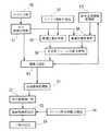
そして、このフレ−ム画像が次々と入力されるときに、この部分画像群から2次元画像を再構成し、指紋照合を行うためには、一般的に、図8に示す次のような手順を利用している。
(1)入力された部分画像と隣接する部分画像との位置関係、すなわちフレ−ム間の指画像の2次元的な移動量を調べる位置合わせを行い(ステップS11,S18)、
(2)この位置合わせの結果にしたがって相互に位置決めした部分画像群から2次元画像S(N)を合成し(ステップS19,S20)、
(3)得られた2次元画像S(N)から照合用の特徴を抽出し(ステップS22)、
(4)抽出した照合用の特徴と予め求めておいた登録指紋(テンプレ−ト)の特徴とを照合し(ステップS23)、一致すれば認証完了とする(ステップS24)、という手順で処理している。
【0006】
上記(1)の位置合わせ方法として、逐次類似検出アルゴリズム(SSDA:Sequential Simularity Detection Algorithm)を用いる方法がある。例えば、既に第1フレ−ムから第(n−1)フレ−ム(nは2以上の整数)までのフレ−ム画像が入力され、それらについて位置合わせおよび合成が終了し、その結果として部分合成画像S(n−1;i,j)(iおよびjはそれぞれx座標、y座標)が計算されているとする。ここで、第nフレ−ム画像f(n;i,j)が入力され、これを部分合成画像S(n−1; i,j)に対して位置合わせを行ない、合成するものとする。そのために、SSDA法では、フレーム画像f(n; i,j)を少しずつ平行移動しながら部分合成画像S(n−1; i,j)とフレ−ム画像f(n; i,j)の重ね合わせを試み、最も合ったところをフレ−ム画像f(n; i,j)の位置合わせの最適な移動位置とするものである。これを実現するには、フレ−ム画像f(n; i,j)を(x,y)だけ平行移動した時の2つの画像の濃度値の差の累積(これをペナルティと呼ぶ)c(x,y)を次式により計算し、ペナルティc(x,y)が最小となる(x,y)を求める。
【0007】
【数1】
【0008】
(2)の合成においては、ペナルティc(x,y) を最小にする(x,y)だけフレーム画像f(n; i,j)を平行移動して部分合成画像S(n−1;i,j)と合成し、新たな部分合成画像としてS(n;i,j)を計算すればよい。
【0009】
しかし、センサに対する指の相対的な移動速度が大きく、フレ−ム間の重なり面積が小さい場合、このような方法では最適な移動量を求めることが困難になる。すなわち、ユ−ザが指を速く動かしたときなどには正確な位置合わせができず、正しい2次元画像の再構成の失敗により指紋照合の精度が低下する、という問題がある。逆に言えば、安定した照合動作を保証するためには、ユ−ザは指をゆっくり動かす必要があり、ユ−ザの利便性が下がる、という問題がある。
【0010】
以上述べたように、従来の指紋照合方法や指紋照合装置においては、指紋照合の精度を向上するためには、ユ−ザはセンサ上で指をゆっくり動かす必要があり、ユ−ザの利便性が低下するという問題があった。
【0011】
【発明が解決しようとする課題】
本発明は、上記の問題に鑑みてなされたもので、特に個人用の情報機器においては、登録ユ−ザの指紋デ−タのテンプレ−トは限られた個数しかないという特性を利用することにより、部分画像列が入力されたときの部分画像間のより正確な位置合わせを可能とし、より高精度な指紋照合を実現する指紋照合方法及び装置を提供することを目的とする。
さらには、効率よい位置合わせを実現することにより、処理に必要な計算量を低減して処理の高速化を図り、あるいは処理に使用する演算装置の低価格化を実現すると共に、従来より小面積なセンサにより従来と同程度以上の照合精度を実現することで、センサの低価格化と搭載可能機器の範囲拡大を実現することをも目的とする。
また、特に高精度の照合が要求されないような応用に対して本発明を適用するときには、中程度の精度の照合結果をより高速に、あるいは低演算量で得ることができる指紋照合方法及び装置を提供することも目的とする。
【0012】
【課題を解決するための手段】
上記目的を達成するために、請求項1に記載の発明は、指紋の部分画像の系列を入力し、前記入力された入力指紋と予め登録された登録指紋との同一性の判定を行う指紋識別方法において、前記各部分画像の合成位置を決定するために該登録指紋の画像情報を利用することを特徴とする。
【0013】
請求項2に記載の発明は、請求項1に記載の指紋識別方法において、前記入力指紋と前記登録指紋との同一性の判定は、前記各部分画像について、前記登録指紋の画像の中で該部分画像と最もよく類似する位置を求め、該位置情報に基づいて該部分画像を配置することにより前記各部分画像を合成して合成画像を求め、該合成画像を前記登録指紋の画像と照合し同一性を判定することを特徴とする。
【0014】
請求項3に記載の発明は、請求項1、請求項2に記載の指紋識別方法において、前記入力指紋と前記登録指紋との同一性の判定は、前記各部分画像について前記登録指紋の画像の中で該部分画像と最もよく類似する位置において最小となる第1のペナルティ指標を累積加算し、前記累計加算の結果が所定のペナルティ閾値を超えた場合には前記入力指紋が前記登録指紋と異なるものであると判定することを特徴とする。
【0015】
請求項4に記載の発明は、請求項1、請求項2に記載の指紋識別方法において、前記入力指紋と前記登録指紋との同一性の判定は、前記第1のペナルティ指標の累積加算が所定のペナルティ閾値を超えず、かつ前記部分合成画像の面積が所定の面積閾値を超えた場合には、前記入力指紋が前記登録指紋と類似するものであると判定することを特徴とする。
【0016】
請求項5に記載の発明は、請求項2に記載の指紋識別方法において、前記各部分画像の合成は、前記各部分画像について、前記登録指紋の画像の中で該部分画像と最もよく類似する位置を求めるとともに、それ以前に入力された前記各部分画像から合成された部分合成画像と該部分画像とが最も矛盾なく連続する位置を求め、その結果に基づいて該部分画像を配置して前記各部分画像を合成することを特徴とする。
【0017】
請求項6に記載の発明は、請求項5に記載の指紋識別方法において、前記各部分画像の合成位置の決定は、前記第1のペナルティ指標と、それ以前に計算された前記部分合成画像と最も矛盾なく連続する位置において最小となる第2のペナルティ指標とを計算し、前記第1および第2のペナルティ指標の加重平均にしたがって前記第1のペナルティ指標の計算結果と前記第2のペナルティ指標の計算結果を統合することで合成位置を決定することを特徴とする。
【0018】
請求項7に記載の発明は、請求項5に記載の指紋識別方法において、前記各部分画像の合成位置の決定は、前記部分合成画像がより多くの前記部分画像から合成されるにつれて前記第2のペナルティ指標の重みを増すような加重平均法にしたがって前記第1のペナルティ指標の計算結果と前記第2のペナルティ指標の計算結果を統合し、その結果に基づいて合成位置を決定することを特徴とする。
【0019】
請求項8に記載の発明は、指紋の部分画像の系列を入力し、前記入力された入力指紋と予め登録された登録指紋との同一性の判定を行う指紋識別装置において、前記指紋の部分画像を入力するフレ−ム画像入力手段と、該部分画像と前記登録指紋の画像との最も類似する位置を計算する対登録画像最適位置計算手段と、前記最も類似する位置に配置した該部分画像と既に合成された部分合成画像とを合成し、拡張された部分合成画像を生成する画像合成手段と、前記入力された全ての部分画像を合成した合成画像と前記登録指紋の画像との同一性の判定を行う指紋照合手段と、を具備することを特徴とする。
【0020】
請求項9に記載の発明は、請求項8に記載の指紋識別装置において、前記部分画像についてそれ以前に入力された各部分画像から合成された前記部分合成画像との最も矛盾なく連続する位置を求める対合成画像最適位置計算手段を具備し、前記画像合成手段は前記対登録画像最適位置計算手段の結果と前記対合成画像最適位置計算手段の結果にしたがって該部分画像を合成することを特徴とする。
【0021】
請求項10に記載の発明は、請求項8、請求項9に記載の指紋識別装置において、前記対登録画像最適位置計算手段において前記各部分画像について計算された前記登録指紋の画像の中で該部分画像と最もよく類似する位置において最小となる第1のペナルティ指標を累計加算し、前記累計加算の結果が所定のペナルティ閾値を越えた場合に前記入力指紋と前記登録指紋との不一致を判定する不一致判定手段を具備することを特徴とする。
【0022】
請求項11に記載の発明は、請求項8、請求項9に記載の指紋識別装置において、前記対登録画像最適位置計算手段において計算された前記各部分画像の第1のペナルティ指標を累積加算し、前記累積加算した結果が所定のペナルティ閾値を越えることなく、かつ前記画像合成手段で合成された前記部分合成画像の面積が所定の面積閾値を上回った場合に、前記入力指紋と前記登録指紋との一致を判定する簡易一致判定手段を具備することを特徴とする。
【0023】
【発明の実施の形態】
以下、本発明の実施の形態による指紋識別方法及び装置を図1および図2を参照して説明する。図1は同実施の形態による指紋識別装置のブロック図であり、図2は同実施形態による指紋識別装置のセンサの使用方法を示す図である。本指紋識別装置は個人用の情報機器、例えば情報端末やテレビゲ−ム機、携帯電話などにおいて本人以外が使用できないようにするため、あるいは個人に応じてユ−ザ別の設定をするために、ユ−ザの確認を指紋によって行うものである。
【0024】
図1において、50は本人確認のための指紋画像の入力を行うフレ−ム入力部である。このフレーム入力部50は、カメラ、スキャナなどのように移動する撮像対象の部分画像を連続して得る機能をもち、例えば図2(a)の81のような形状をもつ、指の指紋部分よりは小さい長方形のセンサである。ユ−ザはセンサ81に対して相対的に、例えば矢印のように(あるいは逆方向に)指を動かし、動きに連れて連続的に撮像した指紋の複数の部分画像(フレ−ム)を得る。1枚のフレ−ムと指紋との関係を示すのが図2(b)であり、図2(b)の長方形の部分が1フレームである。フレ−ム入力部50は設定された撮像タイミングごとに、その上に置かれた指の隆線に対応する凹凸を画像の濃度に変換して撮像する。その実現方法としては、例えば特開平10−91769号公報、特開平10−240906号公報、特開平09−116128号公報、特開平10−22641号公報および特開平10−255050号公報に記載されている技術がある。その他にも、プリズムを用いる方式、静電容量を用いる方式などが実用化されている。
【0025】
なお、上記の説明では長方形のセンサ81を仮定しているが、これは必要条件ではなく、例えば図2(c)のような形状のセンサ82で図2(d)のような部分画像を撮像しても同様の効果を上げることができる。この場合、スイ−プ動作は必ずしも上記のように一方向に直線的になされる必要はなく、フレ−ム画像の覆う領域の和集合が最終的に十分広い領域を覆えばよく、より自由なスイ−プをすることが可能である。
【0026】
51は入力されたフレ−ム画像を記憶するフレ−ム画像記憶部、52は予めその情報機器の正規ユ−ザの指紋を登録指紋(テンプレート)として記憶しておくテンプレ−ト画像記憶部である。この登録動作では、例えば他の装置に付属した2次元の(指紋の大部分を十分に覆うだけの広さをもつ)センサを用いて指紋画像を取り込み、その濃淡画像を格納したファイルを外部から情報機器に転送してテンプレ−ト画像記憶部52に記憶させておくことができる。テンプレ−ト画像記憶部52に登録された指紋画像(テンプレート画像)Tの形状の例を図2(e)に示す。53は、それ以前に入力されたフレ−ム画像群から合成された部分合成画像を保持しておく部分合成画像記憶部である。54は、予めその情報機器の正規ユ−ザの指紋画像から照合用の特徴を抽出して記憶しておくテンプレ−ト照合特徴記憶部である。
【0027】
また、55は、フレ−ム画像記憶部51に記録されたフレ−ム画像f(n)とテンプレ−ト画像記憶部52に記憶されているテンプレ−ト画像Tとの位置合わせを行い、最適な位置を決定する最適位置計算部である。この位置合わせの実現方法としては、上記したSSDA法を用いることができる。すなわち、フレ−ム画像f(i,j)(iおよびjはそれぞれx座標およびy座標)をテンプレ−ト画像T(i,j)(iおよびjはそれぞれx座標およびy座標)の全域について少しずつ平行移動しながら両者の重ね合わせを試みて、最も合ったところをフレーム画像f(i,j)の位置合わせの最適な位置とする。これを実現するには、フレーム画像f(i,j)をテンプレート画像T(i,j)の原点に対して(x,y)だけ平行移動した時の2つの画像の濃度値の差の累積(ペナルティ)ペナルティc(x,y)を次式により計算し、ペナルティc(x,y)が最小となる(x,y)を求める。
【0028】
【数2】
【0029】
なお、この位置合わせの実現には、SSDA法の代わりに相互相関法など他の実現方法を用いることもできる。
【0030】
57は、最適位置計算部55で最小のペナルティc(x,y)を与える相対移動量(x,y)の時のペナルティc(x,y)の値がある閾値以下であれば、そのフレ−ムは合成に使用できる有効なフレ−ムであるとしてその位置を合成のための決定位置とし、また、これが閾値を越えていれば、このフレ−ムは合成には使用するべきでないとして、処理を中断し、次のフレ−ムの取り込みに進む、という判断を行う合成用フレ−ム位置決定部である。
【0031】
60は、部分合成画像記憶部53に保持されたそれ以前に入力されたフレ−ム画像群から合成された部分合成画像と、現在処理中のフレ−ム画像とを、合成用フレ−ム位置決定部57の出力する位置情報に基づいて合成する画像合成部である。第nフレ−ムのフレーム画像f(n)が入力された際の合成の様子の一例を図2(f)(n=4の場合)に示す。ここでは上の3つのフレ−ム画像の和集合である薄灰色の部分が部分合成画像記憶部53に保持された、フレ−ム画像群f(1)〜f(n−1)から合成された部分合成画像S(n−1)であり、その下の矩形の部分がフレーム画像f(n)である。合成の方法としては、例えば部分合成画像S(n−1)に、それと重ならないフレーム画像f(n)の新規な領域を付け足して広げる、という方法が可能である。この合成結果は部分合成画像S(n−1)より広い面積をもつ部分合成画像S(n)として、部分合成画像記憶部53に書き込まれる。
【0032】
また、61は、全ての有効なフレ−ムの読み込みと合成が終了した後、最終的な合成結果である合成画像を記憶する合成画像記憶部である。この合成画像が予め定められた閾値以上に広い面積をもつ場合には、この合成画像はユ−ザの指紋のうち照合に十分な広い領域を覆う2次元画像となっている。もし合成画像の面積が閾値に足りない場合には、一連のスイ−プは不十分なものであるとしてユ−ザに再スイ−プを指示する。
【0033】
62は、合成画像記憶部61に保持された2次元の合成画像から照合用の特徴を抽出する照合特徴抽出部である。また、63は、テンプレ−ト照合特徴記憶部54に保持された正規ユ−ザの指紋特徴と、照合特徴抽出部62で計算された今回指紋を入力しているユ−ザの指紋特徴を照合し、その類似度を出力する指紋特徴照合部である。この指紋特徴抽出部62、指紋特徴照合部63を含む指紋照合装置の実現例としては、特開昭56−24675号公報や特開平4−33065号公報に記載された「指紋照合装置」がある。これらの技術では、指紋等の照合に際して、指紋紋様を特徴付ける各特徴点の位置および方向とともに、各特徴点により固有に決定される局所座標系を複数個の扇形領域に分割した近傍における最近傍点と上記特徴点との隆線数、すなわちリレ−ションを検査することによって、安定かつ精度の高い照合を可能にしている。
【0034】
64は、指紋特徴照合部63での照合結果の類似度が高ければ一致であるとしてユ−ザにその情報機器の利用を許可し、類似度が低ければ不一致であるとして利用を許可しないなど所定の動作を行う一致判定部である。
【0035】
次に、本実施形態の動作を図3を参照して説明する。図3は、本実施形態の指紋識別方法を示すフローチャートである。本実施形態を適用する情報機器は、例えば携帯電話機などの機器であり、その正規ユ−ザが所有者一人であるとする。所有者Aは情報機器の使用開始時などに、予めその指紋デ−タを本指紋識別装置に登録する。そのときの入力は、例えば外部の指紋入力スキャナで指紋の十分な広さの領域を含む2次元の画像デ−タを撮り、この画像デ−タをテンプレート画像として図1のテンプレ−ト画像記憶部52に記憶させる。それとともに、そのテンプレート画像Tを照合特徴抽出部62、または同じ機能をもつ外部装置に入力して計算された、照合で用いられるテンプレート画像Tの指紋特徴をテンプレ−ト照合特徴記憶部54に記憶させる。
【0036】
その情報機器のうちユ−ザ認証を必要とする機能をあるユ−ザXが使用しようとする際、ユーザXはその指紋をセンサ上でスイ−プする。これによりセンサの形状に応じた指紋の部分画像であるフレ−ムが入力される。この部分画像の系列をf(1)〜f(n)〜f(N)で表す。第1フレ−ムf(1)が入力される(ステップS11)と、そのフレ−ム画像f(1)と類似する部分をテンプレート画像Tの中で探索する位置合わせが行われる(ステップS12)。入力されたフレ−ムf(1)がテンプレート画像Tと同じ指紋の一部であれば高い類似度をもつ位置が探索できるはずであり、これにより最も類似度が高い、いわば位置合わせの最適位置が決定される(ステップS12)。そして、f(1)については、これをそのまま部分合成画像S(1)とすると共に、この基準点を部分合成画像S(1)についての位置合わせの最適位置として記憶する(ステップS15,S19)。
【0037】
その後、第nフレ−ムf(n)(nは2以上の整数)が入力される(ステップS11)と、同様に、フレームf(n)とテンプレート画像Tとの位置合わせが行われ、最も類似度が高い、すなわちペナルティが小さい位置合わせの最適位置が決定される(ステップS12)。この最適位置とそれまでに決定されているS(n−1)についての基準点位置とを比較することにより、フレーム画像f(n)と部分合成画像S(n−1)とを位置合わせすることが可能であり(ステップ12)、この結果にしたがってフレーム画像f(n)を移動し、部分合成画像S(n−1)とつなぎあわせることで、S(n−1)より拡大された部分合成画像S(n)を作成することができる(ステップS15、S19)。
【0038】
なお、上記の位置合わせにおいて、フレーム画像f(n)とテンプレート画像Tとの類似度あるいは相違度を評価して類似度が予め定められた閾値より低い、あるいは相違度が閾値より高い場合には、このフレ−ム画像f(n)は合成には不適な品質をもつとして棄却して使用しない、という処理を行うことができる。
【0039】
このようなフレ−ム入力と合成動作を繰り返し、全フレ−ムについての処理が終了した時点で得られる2次元の濃淡の合成画像をS(N)とする(ステップS20)。この合成画像S(N)が予め定められた閾値以上に広い面積をもつ場合には、これは十分広い、ユ−ザXの指紋の2次元画像であるので、これを対象として照合用の指紋特徴を抽出する(ステップS22)。このようにして得られた特徴はユ−ザXの指紋の特徴であり、これを保存されている所有者Aの指紋の特徴と照合し(ステップS23)、一致すればユーザXは所有者Aであるとして、その情報機器の使用を許可する(ステップS24)。
【0040】
次に、本発明の第2の実施の形態について図4を参照して説明する。図4は本実施の形態の指紋識別装置のブロック図である。図4において、図1と同一部分には同一符号を付してその説明を省略する。図4において、図1と異なる主な点は、最適位置計算部55の他に、最適位置計算部56を設けたことである。図4において、最適位置計算部55は、フレ−ム画像記憶部51に記憶されたフレ−ム画像f(n)について、テンプレ−ト画像記憶部52に格納されているテンプレ−ト画像Tとの位置合わせを行い、最小ペナルティc1を与える位置p1を計算する。これに対して、最適位置計算部56は、フレ−ム画像記憶部51に記憶されたフレ−ム画像f(n)について、部分合成画像記憶部53に記憶された部分合成画像S(n−1)との位置合わせを行い、最小ペナルティc2を与える位置p2を計算する。これらの位置合わせの実現方法としては、SSDA法を用いることができる。
【0041】
そして、合成用フレ−ム位置決定部58では、最小ペナルティc1とc2の値が共にある閾値以下であれば、そのフレ−ムf(n)は合成に使用できる有効なフレ−ムであるとして、その位置p1およびp2から決定される位置p3を合成のための決定位置とし、また、ペナルティc1、c2のいずれかが閾値を越えていれば、このフレ−ムf(n)は合成には使用するべきでないとして処理を中断し、次のフレ−ムの取り込みに進む、という判断を行う。また、最小ペナルティc1、c2ともに閾値以下である場合、合成のための位置p3の決定法としては、次式で示すように、2つの方向ベクトルp1、p2のそれぞれの最小ペナルティc1、c2の値(類似度に反比例する)の逆数による加重平均をとることで求める。
p3=(c2/(c1+c2))p1+(c1/(c1+c2))p2…(3)
ただし、p1,p2,p3はいずれも2次元の方向ベクトル
【0042】
次に、図5を参照し本実施形態の動作を説明する。図5において、図3と同一部分には同一ステップ符号を付してその説明を省略する。図5において、図3と異なる主な点は、ステップS13およびステップS14の処理を追加していることである。すなわち、フレームf(n)とテンプレート画像Tとの位置合わせが行われ、テンプレート画像Tに対する位置合わせの最小ペナルティc1を与える最適位置p1が計算される(ステップS12)。それと平行して、フレームf(n)と部分合成画像S(n−1)との位置合わせが行われ、部分合成画像S(n−1)に対する位置合わせの最小ペナルティc2を与える最適位置p2が計算される(ステップS13)。
【0043】
そして、この最適位置p1とp2(および最小ペナルティc1とc2)を含む情報から、フレームf(n)を部分合成画像S(n−1)に対して合成するための最適な移動量p3が上記した(3)式により計算され、これと部分合成画像S(n−1)についての基準点位置とを比較することにより、フレームf(n)と部分合成画像S(n−1)との位置合わせが行なわれる(ステップS15)。図5のその他のステップにおける処理内容は、図3の場合と同じである。
【0044】
次に、本発明の第3の実施の形態について図4を参照して説明する。本実施の形態が第2の実施の形態と異なる点は、合成用フレーム位置決定部58における合成位置p3の決定方法である。すなわち、第2の実施の形態では、図4の合成用フレ−ム位置決定部58において、上記の(3)式に示したように最適位置計算部55から得られるテンプレ−ト画像Tとの位置合わせ結果の最適位置p1と、最適位置計算部56から得られる部分合成画像S(n−1)との位置合わせ結果の最適位置p2とを、その最小ペナルティc1、c2に反比例した加重をかけて平均することで統合し、合成位置p3を決定した。
【0045】
これに対して、本実施形態では、部分合成画像S(n−1)がより多くのフレ−ムの合成結果として広い面積をもつほどそれはより信頼できる、という仮定を利用した別の計算法を用いる。すなわち、合成用フレ−ム位置決定部58は、最小ペナルティc1、c2ともに閾値以下である場合、合成位置p3は次式により決定される。
q1=(exp(−Ca))c1/(c1+c2) …(4)
q2=(1−exp(−Ca))c2/(c1+c2) …(5)
p3=q1p1+q2p2 …(6)
但し、p1,p2,p3はいずれも2次元の方向ベクトル
aは合成の入力となる部分合成画像S(n−1)の面積を示す変数
Cは正定数
(4)、(5)式のように、q1,q2は部分合成画像S(n−1)の面積aを考慮に入れて、位置ずれペナルティから計算される各ベクトルの加重を表すことになる。これによれば、最初のフレ−ムf(1)が入力された際、面積aはゼロであるのでq2はゼロとなり、その後、合成に使用したフレ−ム数が大きくなる(すなわちnが大きくなる)にしたがい、部分合成画像S(n−1)の拡張(面積aの増大)と共にq2の寄与が大きくなる。
【0046】
次に、本実施の形態の動作について図5を参照して説明する。本実施の形態が第2の実施の形態と異なる点は、ステップS15における処理内容である。すなわち、ステップS15における合成位置p3の決定が、第2の実施形態においては上記した(3)式により行われるのに対して、本実施形態では上記した(4)、(5)、(6)式により行われる。図5のその他のステップにおける処理内容は、第2の実施の形態の場合と同じである。
【0047】
次に、本発明の第4の実施の形態について図6を参照して説明する。図6は本実施の形態の指紋識別装置を示すブロック図である。本実施の形態では、合成の精度を上げると共に、より少ない計算量でユ−ザの認証を実現することをも目的としている。図6において、図4と同一部分には同一符号を付してその説明を省略する。図6において、図4と異なる主な点は、厳密一致判定部65、簡易一致判定部66、位置ずれペナルティ評価部67、簡易不一致判定部68、品質判定部69を設けていることである。
【0048】
図6において、厳密一致判定部65は、指紋特徴照合部63での照合結果の類似度が高ければ一致であるとしてユ−ザにその情報機器の使用を許可し、類似度が低い場合には、例え簡易不一致判定部68で不一致と判定されなかったとしても、厳密には不一致であるとして許可をしないなど所定の動作を行う。
【0049】
簡易一致判定部66は、最小ペナルティc1の累積値が閾値を越えることなく多くのフレームが合成され、合成結果の画像が一定面積以上に達した場合には、入力指紋はテンプレートと一致している、すなわちユーザXは登録ユーザAと同一である、との簡易的な判定結果を出力する。これは、比較的精度に対する要求が低い応用において、高速に個人識別をするのに有効な方法である。
【0050】
位置ずれペナルティ評価部67は、最適位置計算部55からテンプレ−ト画像Tとの位置合わせの最小ペナルティc1を、最適位置計算部56から部分合成画像S(n−1)との位置合わせの最小ペナルティc2を入力し、nの増加に連れてそれぞれを累積して個別に所定の閾値と比較することで、位置ずれに起因する判定を行う。すなわち、位置ずれペナルティ評価部67の第1の機能は、それまでの画像合成におけるフレ−ム間の整合性(コンシステンシ)の評価のために、フレーム画像f(n)と部分合成画像S(n−1)の位置合わせの最小ペナルティc2の累積値を計算する。また、位置ずれペナルティ評価部67は、テンプレ−ト画像Tの登録指紋と入力された入力指紋との同一性の評価のために、フレーム画像f(n)とテンプレ−ト画像Tの位置合わせの最小ペナルティc1の累積値も計算する。
【0051】
簡易不一致判定部部68は、位置ずれペナルティ評価部67で計算されたフレ−ムごとの最小ペナルティc1の累積値が閾値より大きくなった時点で、スイ−プによる指紋入力を行っているユ−ザXの指紋はテンプレ−ト画像Tに登録された正規ユ−ザAの指紋と異なっていると判断し、ユ−ザXに対してその情報機器の使用要求の拒否を通告する。簡易不一致判定部68におけるこのような画像の濃淡レベルの不一致による指紋の違いの判定では一般的に高い精度は期待できないため、精度を必要とする場合には上記した厳密一致判定部65において従来通り指紋特徴による照合を併用する。
【0052】
品質判定部69は、位置ずれペナルティ評価部67で計算されたフレ−ムごとのペナルティc2の累積値が閾値より大きくなった場合、指のセンサに対するスイ−プ(移動)速度が大きい、あるいは指のスイ−プ時の指紋部の弾性変形による指紋の歪みが大きいなどの理由で、合成画像の品質が低いと判断し、ユ−ザXに対して指紋の再入力(再スイ−プ)を要求する。
【0053】
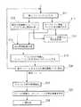
次に、図7を参照し本実施形態の動作を説明する。図7は本実施形態の指紋識別装置方法を示すフローチャートである。図7において、図5と異なる主な点は、ステップS16,S17、S21、S25の部分である。すなわち、フレ−ム画像f(n)とテンプレート画像Tの位置合わせの最小ペナルティc1の累積値を計算し、フレームごとの最小ペナルティc1の累積値が閾値より大きい場合には、ユ−ザXに対してその情報機器の使用要求の拒否を通告する(ステップS16)。
【0054】
また、フレ−ム画像f(n)と部分合成画像S(n−1)の位置合わせの最小ペナルティc2の累積値を計算し、フレ−ムごとのペナルティc2の累積値が閾値より大きい場合は、ユ−ザXに対して指紋の再入力(再スイ−プ)を要求する(ステップS17)。
【0055】
一方、最小ペナルティc1の累積値が上記のように閾値を超えることなく多くのフレ−ムが合成され、合成結果の画像が一定面積以上に達した場合には、入力指紋はテンプレ−ト画像Tと一致している、すなわちユ−ザXは登録ユ−ザAと同一である、との簡易的な判定結果を出力する(ステップS21)。
【0056】
このような画像の濃淡レベルの不一致による指紋の違いの判定は、高い精度は期待できず、いわば簡易的なものである。したがって、さらに高い精度が要求される場合には、第3の実施形態と同様に、合成画像S(N)から照合用の指紋特徴を抽出し(ステップS22)、これを保存されている所有者Aの指紋の特徴と照合し(ステップS23)、厳密な一致判定を行う(ステップS25)。図7のその他のステップの処理内容は、図5の場合と同じである。
【0057】
なお、以上の各実施形態の説明では、本指紋識別装置に登録されるユ−ザは1人であり、テンプレ−トは一指分であるとして説明しているが、例えこれが複数の指であっても、上記したプロセスを各テンプレ−トについて順次行い、そのうちの最小のペナルティを与えるテンプレ−トを選択してその後の処理を実行するように拡張することができる。これにより、1指にとどまらず、少人数で装置を共有し、または1人で複数の指を登録し、入力する指の違いにより動作を変えるという効果を実現することができる。
【0058】
【発明の効果】
以上説明したように、この発明によれば、個人向けの情報機器においては1人ないし少数の利用者のみが登録ユ−ザであることを利用し、小型センサの部分画像(フレ−ム)から全体画像を再構成する際に登録ユ−ザの指紋情報(テンプレ−ト)を用いるようにしたことで、部分画像間のより正確な位置合わせを可能にし、再構成の精度を高めることが可能となる。
これにより、従来の再構成方式では、センサに対する指の相対的な移動速度が大きくフレ−ム間の重なり面積が小さい場合に、最適な移動量を求めることが困難であったのに対し、そのような場合にもより正確な位置合わせが可能になり、照合精度の向上が実現できる。すなわち、安定した照合動作を保証しつつ、ユ−ザの指の動かし方により大きな自由度を与え、ユ−ザの利便性を高めることができる。
さらには、効率よい位置合わせを実現することにより、処理に必要な計算量を低減して処理の高速化を図り、あるいは処理に使用する演算装置の低価格化を実現することができる。
また、従来の2次元型センサを用いるよりは小面積のセンサで同等のユ−ザ確認ができ、面積の増大に連れて高価格となるセンサ部分の低コスト化による装置全体の低価格化と、搭載可能性の増大により、本指紋識別装置の応用範囲の拡大に資することができる。
また、位置合わせペナルティの累積により入力画像とテンプレ−ト画像との一致度を、指紋照合特徴を利用することなく評価することにより、特に高精度の照合が要求されないような応用に対して用いるときには、中程度の精度の照合結果をより高速に、あるいは低演算量で得ることができる。
【図面の簡単な説明】
【図1】 この発明の第1の実施形態による指紋識別装置を示すブロック図である。
【図2】 同実施形態による指紋識別装置のセンサの使用図である。
【図3】 同実施形態による指紋識別方法を示すフロ−チャ−トである。
【図4】 この発明の第2および第3の実施形態による指紋識別装置を示すブロック図である。
【図5】 同実施形態による指紋識別方法を示すフロ−チャ−トである。
【図6】 この発明の第4の実施形態による指紋識別装置を示すブロック図である。
【図7】 同実施形態による指紋識別方法を示すフロ−チャ−トである。
【図8】 一般的な指紋識別方法を示すフロ−チャ−トである。
【符号の説明】
50…フレ−ム入力部、51…フレ−ム画像記憶部、52…テンプレ−ト画像記憶部、53…部分合成画像記憶部、54…テンプレ−ト照合特徴記憶部、55,56…最適位置計算部、57,58…合成用フレ−ム位置決定部、60…画像合成部、61…合成画像記憶部、62…照合特徴抽出部、63…指紋特徴照合部、64…一致判定部、65…厳密一致判定部、66…簡易一致判定部、67…位置ずれペナルティ評価部、68…簡易不一致判定部、69…品質判定部、81,82…センサ[0001]
BACKGROUND OF THE INVENTION
The present invention relates to a fingerprint identification method and apparatus for synthesizing a plurality of input fingerprint partial images and collating fingerprints for personal identification using fingerprints, particularly in information equipment for individuals and small number of users. About.
[0002]
[Prior art]
For user confirmation in information devices and information services, fingerprint identification using the identity of fingerprints with the characteristics of universality and lifelong invariance is effective. In the user confirmation by fingerprint identification, when a certain user X uses the information device or information service, the fingerprint is inputted from the fingerprint input unit, and the inputted user X fingerprint is inputted and stored in advance. The fingerprint data of the authorized user A who is authorized to use the information device or information service (referred to as a template) is checked, and if they match, the user X is authorized. As a result, the use of the information device or information service is permitted.
[0003]
Conventionally, for inputting a fingerprint, an input device using a so-called two-dimensional sensor having a printing surface close to a square that is sufficiently wider than a fingerprint area of a fingertip has been used. However, in order to expand the range of devices that can be mounted by reducing the cost and size of the input device, an input device having a sensor surface that is smaller than the fingerprint region is used. It is effective to perform a fingerprint collation by using a plurality of partial image sequences obtained by relatively moving (referred to as a sweep operation).
[0004]
As an example using this small area sensor, the technique described in Japanese Patent Laid-Open No. 10-91769 has a long side width approximately the width of a finger, and the length in the short side direction is longer than the long side width. Method of synthesizing a two-dimensional image for verification from a partial image sequence obtained by using a rectangular sensor having a shape close to a one-dimensional line type, which is quite short, and sliding a finger in the short-side direction on the sensor Is stated. In this case, when the finger is moved on the line-shaped sensor and the sensor sequentially captures grayscale images corresponding to the ridge pattern of the fingerprint thereon as time passes, the line-shaped image is viewed from the input device side. A rectangular partial image sequence that is a grayscale image is input as time passes. A partial image obtained by one imaging at this time is called a frame or frame image.
[0005]
In order to reconstruct a two-dimensional image from the partial image group and perform fingerprint collation when the frame images are successively input, generally, the following procedure shown in FIG. Is used.
(1) Alignment for examining the positional relationship between the input partial image and the adjacent partial image, that is, the two-dimensional movement amount of the finger image between frames (steps S11 and S18),
(2) A two-dimensional image S (N) is synthesized from the group of partial images positioned according to the result of this alignment (steps S19 and S20),
(3) Extracting features for matching from the obtained two-dimensional image S (N) (step S22),
(4) The extracted feature for collation is collated with the characteristics of the registered fingerprint (template) obtained in advance (step S23), and if they match, the authentication is completed (step S24). ing.
[0006]
As an alignment method of the above (1), there is a method using a sequential similarity detection algorithm (SSDA: Sequential Similarity Detection Algorithm). For example, frame images from the first frame to the (n-1) th frame (n is an integer of 2 or more) are already input, and the registration and composition are finished for them, and as a result It is assumed that the composite image S (n−1; i, j) (i and j are x-coordinate and y-coordinate, respectively) is calculated. Here, it is assumed that the nth frame image f (n; i, j) is input, is aligned with the partially synthesized image S (n−1; i, j), and is synthesized. Therefore, in the SSDA method, the partial composite image S (n−1; i, j) and the frame image f (n; i, j) are translated while gradually moving the frame image f (n; i, j). And the most suitable position is set as the optimum movement position for alignment of the frame image f (n; i, j). To achieve this, accumulation of the difference between the density values of the two images when the frame image f (n; i, j) is translated by (x, y) (this is called a penalty) c ( x, y) is calculated by the following equation, and (x, y) that minimizes the penalty c (x, y) is obtained.
[0007]
[Expression 1]
[0008]
In the synthesis of (2), the frame image f (n; i, j) is translated by (x, y) to minimize the penalty c (x, y) and the partial synthesized image S (n−1; i). , J) and S (n; i, j) may be calculated as a new partial composite image.
[0009]
However, when the relative movement speed of the finger with respect to the sensor is large and the overlapping area between the frames is small, it is difficult to obtain an optimum movement amount by such a method. That is, there is a problem that accurate positioning cannot be performed when the user moves his / her finger quickly, and the accuracy of fingerprint collation is lowered due to a failure in reconstructing a correct two-dimensional image. In other words, in order to guarantee a stable collation operation, the user needs to move his / her finger slowly, and there is a problem that the convenience of the user is lowered.
[0010]
As described above, in the conventional fingerprint collation method and fingerprint collation apparatus, in order to improve the accuracy of fingerprint collation, the user needs to move his / her finger slowly on the sensor, which is convenient for the user. There was a problem that decreased.
[0011]
[Problems to be solved by the invention]
The present invention has been made in view of the above problems, and in particular for personal information devices, it utilizes the characteristic that there are only a limited number of fingerprint data templates for registered users. Accordingly, it is an object of the present invention to provide a fingerprint collation method and apparatus that enables more accurate alignment between partial images when a partial image sequence is input and realizes higher-accuracy fingerprint collation.
In addition, by realizing efficient alignment, the amount of calculation required for processing is reduced and processing speed is increased, or the price of the arithmetic unit used for processing is reduced, and the area is smaller than before. It is also an object of the present invention to realize a reduction in the price of the sensor and expansion of the range of devices that can be mounted by realizing a matching accuracy equal to or higher than that of a conventional sensor.
In addition, when applying the present invention to an application that does not particularly require high-precision collation, a fingerprint collation method and apparatus capable of obtaining a medium-precision collation result at a higher speed or with a lower amount of computation. It is also intended to provide.
[0012]
[Means for Solving the Problems]
In order to achieve the above object, the invention according to claim 1 is a fingerprint identification method for inputting a partial image sequence of a fingerprint and determining the identity of the input fingerprint and a registered fingerprint registered in advance. In the method, the image information of the registered fingerprint is used to determine a synthesis position of each partial image.
[0013]
According to a second aspect of the present invention, in the fingerprint identification method according to the first aspect, the determination of the identity between the input fingerprint and the registered fingerprint is performed in the image of the registered fingerprint for each partial image. A position that is most similar to the partial image is obtained, and the partial images are arranged based on the position information to synthesize the partial images to obtain a composite image, and the composite image is collated with the image of the registered fingerprint. It is characterized by determining identity.
[0014]
According to a third aspect of the present invention, in the fingerprint identification method according to the first or second aspect, the identity determination between the input fingerprint and the registered fingerprint is performed on the image of the registered fingerprint for each partial image. Among them, the first penalty index that is the smallest at the position most similar to the partial image is cumulatively added, and the input fingerprint is different from the registered fingerprint when the result of the cumulative addition exceeds a predetermined penalty threshold It is characterized by determining that it is a thing.
[0015]
According to a fourth aspect of the present invention, in the fingerprint identification method according to the first or second aspect of the invention, the determination of the identity between the input fingerprint and the registered fingerprint is performed by a cumulative addition of the first penalty index. When the penalty threshold is not exceeded and the area of the partial composite image exceeds a predetermined area threshold, it is determined that the input fingerprint is similar to the registered fingerprint.
[0016]
According to a fifth aspect of the present invention, in the fingerprint identification method according to the second aspect, the synthesis of the partial images is most similar to the partial image among the registered fingerprint images for the partial images. Obtaining a position, obtaining a position where the partial composite image synthesized from each partial image input before that and the partial image continue most consistently, and arranging the partial image based on the result, Each partial image is synthesized.
[0017]
According to a sixth aspect of the present invention, in the fingerprint identification method according to the fifth aspect of the present invention, the composite position of each partial image is determined by the first penalty index, the partial composite image calculated before that, Calculating a second penalty index that is the smallest at consecutive positions without contradiction, and calculating the first penalty index and the second penalty index according to a weighted average of the first and second penalty indices The synthesis position is determined by integrating the calculation results of the above.
[0018]
According to a seventh aspect of the present invention, in the fingerprint identification method according to the fifth aspect, the determination of the synthesis position of each of the partial images is performed as the partial synthesized image is synthesized from more partial images. The calculation result of the first penalty index and the calculation result of the second penalty index are integrated according to a weighted average method that increases the weight of the penalty index, and a composite position is determined based on the result. And
[0019]
According to an eighth aspect of the present invention, in the fingerprint identification device for inputting a series of fingerprint partial images and determining the identity between the inputted input fingerprint and a registered fingerprint registered in advance, the partial image of the fingerprint Frame image input means for inputting the image, a registered image optimum position calculation means for calculating the most similar position between the partial image and the registered fingerprint image, and the partial image arranged at the most similar position An image synthesis means for synthesizing an already synthesized partial synthesized image to generate an extended partial synthesized image, and a synthesized image obtained by synthesizing all the input partial images and the image of the registered fingerprint. And fingerprint collating means for performing the determination.
[0020]
According to a ninth aspect of the present invention, in the fingerprint identification device according to the eighth aspect of the present invention, the position where the partial image is continuous with the partial composite image synthesized from each partial image input before is most consistent. A pair-combined image optimum position calculating means to be obtained, wherein the image composition means combines the partial images according to the result of the pair-registered image optimum position calculating means and the result of the pair-combined image optimum position calculating means. To do.
[0021]
According to a tenth aspect of the present invention, in the fingerprint identification device according to the eighth or ninth aspect, the image of the registered fingerprint calculated for each partial image in the paired image optimum position calculating means is the fingerprint image. The first penalty index that is the smallest at the position most similar to the partial image is cumulatively added, and when the result of the cumulative addition exceeds a predetermined penalty threshold, a mismatch between the input fingerprint and the registered fingerprint is determined. A mismatch determination means is provided.
[0022]
The invention according to
[0023]
DETAILED DESCRIPTION OF THE INVENTION
Hereinafter, a fingerprint identification method and apparatus according to an embodiment of the present invention will be described with reference to FIGS. FIG. 1 is a block diagram of the fingerprint identification device according to the embodiment, and FIG. 2 is a diagram illustrating a method of using the sensor of the fingerprint identification device according to the embodiment. This fingerprint identification device can be used by personal information devices such as information terminals, TV game machines, mobile phones, etc., to prevent use by anyone other than the user, or to make user-specific settings according to the individual. The user is confirmed by a fingerprint.
[0024]
In FIG. 1,
[0025]
In the above description, the
[0026]
51 is a frame image storage unit for storing the input frame image, and 52 is a template image storage unit for storing a fingerprint of a regular user of the information device in advance as a registered fingerprint (template). is there. In this registration operation, for example, a fingerprint image is captured using a two-dimensional sensor attached to another device (which has a size sufficient to cover most of the fingerprint), and a file storing the grayscale image is externally stored. It can be transferred to an information device and stored in the template
[0027]
[0028]
[Expression 2]
[0029]
In order to realize this alignment, other realization methods such as a cross-correlation method can be used instead of the SSDA method.
[0030]
57, if the value of the penalty c (x, y) at the time of the relative movement amount (x, y) giving the minimum penalty c (x, y) in the optimum
[0031]
[0032]
[0033]
[0034]
64 indicates that if the similarity of the collation result in the fingerprint
[0035]
Next, the operation of this embodiment will be described with reference to FIG. FIG. 3 is a flowchart showing the fingerprint identification method of this embodiment. An information device to which this embodiment is applied is a device such as a mobile phone, for example, and it is assumed that the authorized user is one owner. The owner A registers the fingerprint data in the fingerprint identification device in advance at the start of use of the information device. At this time, for example, an external fingerprint input scanner is used to take two-dimensional image data including a sufficiently wide area of the fingerprint, and this image data is used as a template image to store the template image shown in FIG. Store in the
[0036]
When a user X who wants to use a function that requires user authentication among the information devices, the user X swipes the fingerprint on the sensor. As a result, a frame which is a partial image of a fingerprint corresponding to the shape of the sensor is input. This series of partial images is represented by f (1) to f (n) to f (N). When the first frame f (1) is input (step S11), alignment for searching for a portion similar to the frame image f (1) in the template image T is performed (step S12). . If the input frame f (1) is a part of the same fingerprint as that of the template image T, a position having a high similarity should be searched. Is determined (step S12). For f (1), this is used as the partial composite image S (1) as it is, and this reference point is stored as the optimum position for alignment for the partial composite image S (1) (steps S15 and S19). .
[0037]
Thereafter, when the nth frame f (n) (n is an integer equal to or greater than 2) is input (step S11), the frame f (n) and the template image T are similarly aligned. An optimum position for alignment with a high degree of similarity, that is, a small penalty is determined (step S12). The frame image f (n) and the partial composite image S (n−1) are aligned by comparing this optimum position with the reference point position for S (n−1) determined so far. (Step 12), and the frame image f (n) is moved according to the result and joined with the partial composite image S (n-1), so that the portion enlarged from S (n-1). A composite image S (n) can be created (steps S15 and S19).
[0038]
In the above alignment, when the similarity or dissimilarity between the frame image f (n) and the template image T is evaluated and the similarity is lower than a predetermined threshold or the difference is higher than the threshold. The frame image f (n) can be processed so as to be rejected and not used because it has unsuitable quality for synthesis.
[0039]
Such a frame input and composition operation is repeated, and a two-dimensional grayscale composite image obtained when processing for all the frames is completed is defined as S (N) (step S20). When the composite image S (N) has an area larger than a predetermined threshold value, this is a sufficiently wide two-dimensional image of the fingerprint of the user X. Features are extracted (step S22). The characteristic obtained in this way is the characteristic of the fingerprint of user X, which is collated with the characteristic of the stored fingerprint of owner A (step S23). As a result, use of the information device is permitted (step S24).
[0040]
Next, a second embodiment of the present invention will be described with reference to FIG. FIG. 4 is a block diagram of the fingerprint identification apparatus according to the present embodiment. In FIG. 4, the same parts as those in FIG. 4 is different from FIG. 1 in that an optimum
[0041]
The composition frame
p3 = (c2 / (c1 + c2)) p1 + (c1 / (c1 + c2)) p2 (3)
However, p1, p2, and p3 are all two-dimensional direction vectors.
[0042]
Next, the operation of this embodiment will be described with reference to FIG. In FIG. 5, the same steps as those in FIG. In FIG. 5, the main point different from FIG. 3 is that the processing of step S13 and step S14 is added. That is, alignment between the frame f (n) and the template image T is performed, and an optimum position p1 that gives a minimum alignment penalty c1 with respect to the template image T is calculated (step S12). In parallel with this, alignment between the frame f (n) and the partial composite image S (n-1) is performed, and an optimum position p2 that gives a minimum penalty c2 for alignment with respect to the partial composite image S (n-1) is obtained. Calculated (step S13).
[0043]
From the information including the optimum positions p1 and p2 (and the minimum penalties c1 and c2), the optimum movement amount p3 for synthesizing the frame f (n) with the partial synthesized image S (n−1) is the above-mentioned. The position of the frame f (n) and the partial composite image S (n-1) is calculated by the equation (3) and compared with the reference point position for the partial composite image S (n-1). Matching is performed (step S15). The processing contents in other steps in FIG. 5 are the same as those in FIG.
[0044]
Next, a third embodiment of the present invention will be described with reference to FIG. The present embodiment is different from the second embodiment in the method for determining the synthesis position p3 in the synthesis frame
[0045]
On the other hand, in the present embodiment, another calculation method using an assumption that the partial composite image S (n−1) has a larger area as a result of combining more frames is more reliable. Use. That is, the composition frame
q1 = (exp (−Ca)) c1 / (c1 + c2) (4)
q2 = (1-exp (−Ca)) c2 / (c1 + c2) (5)
p3 = q1p1 + q2p2 (6)
Where p1, p2, and p3 are both two-dimensional direction vectors
a is a variable indicating the area of the partial composite image S (n−1) as an input of the composite
C is a positive constant
As in equations (4) and (5), q1 and q2 represent the weight of each vector calculated from the positional deviation penalty, taking into account the area a of the partial composite image S (n-1). . According to this, when the first frame f (1) is inputted, since the area a is zero, q2 becomes zero, and thereafter, the number of frames used for synthesis increases (that is, n increases). Accordingly, the contribution of q2 increases as the partial composite image S (n-1) is expanded (increase in the area a).
[0046]
Next, the operation of the present embodiment will be described with reference to FIG. The difference between the present embodiment and the second embodiment is the processing content in step S15. That is, the determination of the synthesis position p3 in step S15 is performed by the above-described expression (3) in the second embodiment, whereas in the present embodiment, the above-described (4), (5), (6) It is done by the formula. The processing contents in other steps in FIG. 5 are the same as those in the second embodiment.
[0047]
Next, a fourth embodiment of the present invention will be described with reference to FIG. FIG. 6 is a block diagram showing the fingerprint identification apparatus of the present embodiment. The purpose of the present embodiment is to increase the accuracy of synthesis and to realize user authentication with a smaller amount of calculation. In FIG. 6, the same parts as those in FIG. 6 is different from FIG. 4 in that an exact
[0048]
In FIG. 6, the exact
[0049]
The simple
[0050]
The misalignment
[0051]
The simple
[0052]
When the cumulative value of the penalty c2 for each frame calculated by the positional deviation
[0053]
Next, the operation of this embodiment will be described with reference to FIG. FIG. 7 is a flowchart showing the fingerprint identification method according to this embodiment. In FIG. 7, the main points different from FIG. 5 are steps S16, S17, S21, and S25. That is, the cumulative value of the minimum penalty c1 of the alignment between the frame image f (n) and the template image T is calculated, and if the cumulative value of the minimum penalty c1 for each frame is larger than the threshold, the user X is The rejection of the use request for the information device is notified (step S16).
[0054]
In addition, when the cumulative value of the minimum penalty c2 of the alignment between the frame image f (n) and the partial composite image S (n-1) is calculated, and the cumulative value of the penalty c2 for each frame is larger than the threshold value. The user X is requested to re-input (re-sweep) the fingerprint (step S17).
[0055]
On the other hand, when many frames are synthesized without the cumulative value of the minimum penalty c1 exceeding the threshold value as described above, and the resulting image has reached a certain area or more, the input fingerprint is the template image T. That is, that is, the user X is the same as the registered user A is output (step S21).
[0056]
Such a determination of a difference in fingerprints due to a mismatch in light and shade levels of images cannot be expected to be highly accurate, and is so simple. Therefore, when higher accuracy is required, the fingerprint feature for verification is extracted from the composite image S (N) as in the third embodiment (step S22), and the stored owner is stored. It is collated with the characteristics of the fingerprint of A (step S23), and exact matching determination is performed (step S25). The processing contents of other steps in FIG. 7 are the same as those in FIG.
[0057]
In the above description of each embodiment, it is described that one user is registered in the fingerprint identification apparatus and one template is used for one finger. Even so, the above-described process can be performed sequentially for each template, and the template that gives the minimum penalty can be selected and extended to execute the subsequent processing. Thereby, it is possible to realize an effect that the device is shared by a small number of people, or a plurality of fingers are registered by one person, and the operation is changed depending on the input finger.
[0058]
【The invention's effect】
As described above, according to the present invention, since only one or a small number of users are registered users in a personal information device, a partial image (frame) of a small sensor can be used. By using the registered user's fingerprint information (template) when reconstructing the whole image, it is possible to more accurately align the partial images and increase the accuracy of reconstruction. It becomes.
As a result, in the conventional reconstruction method, when the relative movement speed of the finger with respect to the sensor is large and the overlapping area between the frames is small, it is difficult to obtain the optimum movement amount. Even in such a case, it is possible to perform more accurate positioning and to improve collation accuracy. That is, it is possible to give a greater degree of freedom to the user's finger movement and to improve the user's convenience while guaranteeing a stable collation operation.
Furthermore, by realizing efficient alignment, it is possible to reduce the amount of calculation necessary for processing to increase the processing speed, or to reduce the price of an arithmetic device used for processing.
In addition, it is possible to confirm the same user with a small area sensor rather than using a conventional two-dimensional sensor, and to reduce the cost of the entire device by reducing the cost of the sensor part, which becomes more expensive as the area increases. The increase in the mounting possibility can contribute to the expansion of the application range of the fingerprint identification device.
In addition, when the degree of coincidence between the input image and the template image is evaluated without using the fingerprint collation feature by accumulating the alignment penalty, it is used for an application in which high-precision collation is not particularly required. Therefore, it is possible to obtain a collation result with a medium accuracy at a higher speed or with a lower calculation amount.
[Brief description of the drawings]
FIG. 1 is a block diagram showing a fingerprint identification device according to a first embodiment of the present invention.
FIG. 2 is a usage diagram of a sensor of the fingerprint identification device according to the embodiment.
FIG. 3 is a flowchart showing a fingerprint identification method according to the embodiment.
FIG. 4 is a block diagram showing a fingerprint identification device according to second and third embodiments of the present invention.
FIG. 5 is a flowchart showing a fingerprint identification method according to the embodiment.
FIG. 6 is a block diagram showing a fingerprint identification device according to a fourth embodiment of the present invention.
FIG. 7 is a flowchart showing a fingerprint identification method according to the embodiment.
FIG. 8 is a flowchart showing a general fingerprint identification method.
[Explanation of symbols]
DESCRIPTION OF
Claims (11)
Translated fromJapanese前記指紋の部分画像を入力するフレ−ム画像入力手段と、
該部分画像と前記登録指紋の画像との最も類似する位置を計算する対登録画像最適位置計算手段と、
前記最も類似する位置に配置した該部分画像と既に合成された部分合成画像とを合成し、拡張された部分合成画像を生成する画像合成手段と、
前記入力された全ての部分画像を合成した合成画像と前記登録指紋の画像との同一性の判定を行う指紋照合手段と、
を具備することを特徴とする指紋識別装置。In a fingerprint identification device that inputs a series of fingerprint partial images and determines the identity of the input fingerprint and a registered fingerprint registered in advance,
A frame image input means for inputting a partial image of the fingerprint;
A registered image optimum position calculating means for calculating the most similar position between the partial image and the registered fingerprint image;
Image synthesizing means for synthesizing the partial image arranged at the most similar position and the already synthesized partial synthetic image to generate an expanded partial synthetic image;
Fingerprint collation means for determining the identity of the synthesized image obtained by synthesizing all the input partial images and the image of the registered fingerprint;
A fingerprint identification device comprising:
Priority Applications (6)
| Application Number | Priority Date | Filing Date | Title |
|---|---|---|---|
| JP2000230042AJP3780830B2 (en) | 2000-07-28 | 2000-07-28 | Fingerprint identification method and apparatus |
| EP01954348AEP1306804B1 (en) | 2000-07-28 | 2001-07-26 | Fingerprint identification method and apparatus |
| US10/333,755US7194115B2 (en) | 2000-07-28 | 2001-07-26 | Fingerprint identification method and apparatus |
| DE60141207TDE60141207D1 (en) | 2000-07-28 | 2001-07-26 | METHOD AND DEVICE FOR IDENTIFYING FINGERPRINTS |
| PCT/JP2001/006445WO2002011066A1 (en) | 2000-07-28 | 2001-07-26 | Fingerprint identification method and apparatus |
| KR1020037001187AKR100564076B1 (en) | 2000-07-28 | 2001-07-26 | Fingerprint Identification Method and Device |
Applications Claiming Priority (1)
| Application Number | Priority Date | Filing Date | Title |
|---|---|---|---|
| JP2000230042AJP3780830B2 (en) | 2000-07-28 | 2000-07-28 | Fingerprint identification method and apparatus |
Publications (2)
| Publication Number | Publication Date |
|---|---|
| JP2002042136A JP2002042136A (en) | 2002-02-08 |
| JP3780830B2true JP3780830B2 (en) | 2006-05-31 |
Family
ID=18723060
Family Applications (1)
| Application Number | Title | Priority Date | Filing Date |
|---|---|---|---|
| JP2000230042AExpired - Fee RelatedJP3780830B2 (en) | 2000-07-28 | 2000-07-28 | Fingerprint identification method and apparatus |
Country Status (6)
| Country | Link |
|---|---|
| US (1) | US7194115B2 (en) |
| EP (1) | EP1306804B1 (en) |
| JP (1) | JP3780830B2 (en) |
| KR (1) | KR100564076B1 (en) |
| DE (1) | DE60141207D1 (en) |
| WO (1) | WO2002011066A1 (en) |
Cited By (1)
| Publication number | Priority date | Publication date | Assignee | Title |
|---|---|---|---|---|
| US11288346B1 (en)* | 2014-03-03 | 2022-03-29 | Charles Schwab & Co., Inc. | System and method for authenticating users using weak authentication techniques, with differences for different features |
Families Citing this family (99)
| Publication number | Priority date | Publication date | Assignee | Title |
|---|---|---|---|---|
| SE0100887D0 (en)* | 2001-03-15 | 2001-03-15 | Fingerprint Cards Ab | Device and method for processing fingerprint information |
| JP3902473B2 (en)* | 2002-01-17 | 2007-04-04 | 富士通株式会社 | Identification method using biometric information |
| CN1235172C (en)* | 2002-02-20 | 2006-01-04 | 佳能株式会社 | Image input device |
| JP2003242489A (en)* | 2002-02-20 | 2003-08-29 | Canon Inc | Image input device and fingerprint recognition device |
| JP4027118B2 (en)* | 2002-02-25 | 2007-12-26 | 富士通株式会社 | User authentication method, program, and apparatus |
| KR100467279B1 (en)* | 2002-03-12 | 2005-01-24 | 테스텍 주식회사 | Method for Registering Image of Finger Print |
| AU2002328437A1 (en)* | 2002-09-17 | 2004-04-08 | Fujitsu Limited | Biological information acquiring apparatus and authentication apparatus using biological information |
| JP2004110438A (en) | 2002-09-18 | 2004-04-08 | Nec Corp | Image processing device, image processing method, and program |
| JP4262471B2 (en) | 2002-11-12 | 2009-05-13 | 富士通株式会社 | Biometric feature data acquisition device |
| DE10339743B4 (en)* | 2003-08-28 | 2007-08-02 | Infineon Technologies Ag | A method of comparing a test fingerprint with a stored reference fingerprint and apparatus suitable for performing the method |
| FR2862785B1 (en)* | 2003-11-21 | 2006-01-20 | Atmel Grenoble Sa | DIGITAL SENSOR SENSOR WITH TWO SCANNING DIRECTIONS |
| US20050152585A1 (en)* | 2004-01-13 | 2005-07-14 | Will Shatford | Print analysis |
| GB2414616A (en)* | 2004-05-28 | 2005-11-30 | Sony Uk Ltd | Comparing test image with a set of reference images |
| JP4454335B2 (en)* | 2004-02-12 | 2010-04-21 | Necインフロンティア株式会社 | Fingerprint input device |
| JP3996133B2 (en)* | 2004-02-16 | 2007-10-24 | シャープ株式会社 | Image collation device, image collation method, image collation program, and computer-readable recording medium on which image collation program is recorded |
| US7336841B2 (en)* | 2004-03-25 | 2008-02-26 | Intel Corporation | Fingerprinting digital video for rights management in networks |
| US8175345B2 (en) | 2004-04-16 | 2012-05-08 | Validity Sensors, Inc. | Unitized ergonomic two-dimensional fingerprint motion tracking device and method |
| US8358815B2 (en)* | 2004-04-16 | 2013-01-22 | Validity Sensors, Inc. | Method and apparatus for two-dimensional finger motion tracking and control |
| US8131026B2 (en) | 2004-04-16 | 2012-03-06 | Validity Sensors, Inc. | Method and apparatus for fingerprint image reconstruction |
| US8447077B2 (en) | 2006-09-11 | 2013-05-21 | Validity Sensors, Inc. | Method and apparatus for fingerprint motion tracking using an in-line array |
| US8229184B2 (en) | 2004-04-16 | 2012-07-24 | Validity Sensors, Inc. | Method and algorithm for accurate finger motion tracking |
| US7574022B2 (en)* | 2004-05-20 | 2009-08-11 | Atrua Technologies | Secure system and method of creating and processing partial finger images |
| US9286457B2 (en) | 2004-06-14 | 2016-03-15 | Rodney Beatson | Method and system for providing password-free, hardware-rooted, ASIC-based authentication of a human to a mobile device using biometrics with a protected, local template to release trusted credentials to relying parties |
| JP4411152B2 (en)* | 2004-07-05 | 2010-02-10 | Necインフロンティア株式会社 | Fingerprint reading method, fingerprint reading system and program |
| JP4339221B2 (en)* | 2004-09-30 | 2009-10-07 | Necインフロンティア株式会社 | Image construction method, fingerprint image construction apparatus and program |
| DE602005022900D1 (en) | 2004-10-04 | 2010-09-23 | Validity Sensors Inc | FINGERPRINTER CONSTRUCTIONS WITH ONE SUBSTRATE |
| JP4501627B2 (en)* | 2004-10-19 | 2010-07-14 | カシオ計算機株式会社 | Image collation device, image collation method, and image collation program |
| US7756358B2 (en)* | 2004-11-30 | 2010-07-13 | Hewlett-Packard Development Company, L.P. | System and method of aligning images |
| KR100699026B1 (en)* | 2004-12-24 | 2007-03-27 | 현대정보기술주식회사 | Fingerprint Template Generator Apparatus and Method Using Sweeping Sensor |
| KR100747446B1 (en)* | 2005-03-07 | 2007-08-09 | 엘지전자 주식회사 | Fingerprint recognition device and method of mobile terminal |
| TWI303388B (en)* | 2005-03-18 | 2008-11-21 | Egis Technology Inc | A sweep-type image sensing chip with image matching function and processing method therefor |
| US8194946B2 (en)* | 2005-07-28 | 2012-06-05 | Fujifilm Corporation | Aligning apparatus, aligning method, and the program |
| JP4547629B2 (en)* | 2006-02-10 | 2010-09-22 | ソニー株式会社 | Registration device, registration method, and registration program |
| JP4427039B2 (en)* | 2006-08-18 | 2010-03-03 | 富士通株式会社 | Biometric information acquisition apparatus and biometric information authentication apparatus |
| US8290150B2 (en) | 2007-05-11 | 2012-10-16 | Validity Sensors, Inc. | Method and system for electronically securing an electronic device using physically unclonable functions |
| JP4389971B2 (en)* | 2007-06-19 | 2009-12-24 | ミツミ電機株式会社 | Fingerprint image forming apparatus and finger movement amount estimation method used therefor |
| US20090044023A1 (en)* | 2007-08-07 | 2009-02-12 | Alex Crumlin | Control device with an integrated user interface |
| US8204281B2 (en) | 2007-12-14 | 2012-06-19 | Validity Sensors, Inc. | System and method to remove artifacts from fingerprint sensor scans |
| US8276816B2 (en) | 2007-12-14 | 2012-10-02 | Validity Sensors, Inc. | Smart card system with ergonomic fingerprint sensor and method of using |
| US8116540B2 (en) | 2008-04-04 | 2012-02-14 | Validity Sensors, Inc. | Apparatus and method for reducing noise in fingerprint sensing circuits |
| JP5040835B2 (en)* | 2008-07-04 | 2012-10-03 | 富士通株式会社 | Biological information reader, biological information reading method, and biological information reading program |
| US8698594B2 (en) | 2008-07-22 | 2014-04-15 | Synaptics Incorporated | System, device and method for securing a user device component by authenticating the user of a biometric sensor by performance of a replication of a portion of an authentication process performed at a remote computing device |
| JP5206218B2 (en)* | 2008-08-20 | 2013-06-12 | 富士通株式会社 | Fingerprint image acquisition device, fingerprint authentication device, fingerprint image acquisition method, and fingerprint authentication method |
| US8391568B2 (en) | 2008-11-10 | 2013-03-05 | Validity Sensors, Inc. | System and method for improved scanning of fingerprint edges |
| US8600122B2 (en) | 2009-01-15 | 2013-12-03 | Validity Sensors, Inc. | Apparatus and method for culling substantially redundant data in fingerprint sensing circuits |
| US8278946B2 (en) | 2009-01-15 | 2012-10-02 | Validity Sensors, Inc. | Apparatus and method for detecting finger activity on a fingerprint sensor |
| US8374407B2 (en) | 2009-01-28 | 2013-02-12 | Validity Sensors, Inc. | Live finger detection |
| US9336428B2 (en) | 2009-10-30 | 2016-05-10 | Synaptics Incorporated | Integrated fingerprint sensor and display |
| US9274553B2 (en) | 2009-10-30 | 2016-03-01 | Synaptics Incorporated | Fingerprint sensor and integratable electronic display |
| US8421890B2 (en) | 2010-01-15 | 2013-04-16 | Picofield Technologies, Inc. | Electronic imager using an impedance sensor grid array and method of making |
| US8866347B2 (en) | 2010-01-15 | 2014-10-21 | Idex Asa | Biometric image sensing |
| US8791792B2 (en) | 2010-01-15 | 2014-07-29 | Idex Asa | Electronic imager using an impedance sensor grid array mounted on or about a switch and method of making |
| JP5482803B2 (en)* | 2010-01-28 | 2014-05-07 | 富士通株式会社 | Biological information processing apparatus, biological information processing method, and biological information processing program |
| US9666635B2 (en) | 2010-02-19 | 2017-05-30 | Synaptics Incorporated | Fingerprint sensing circuit |
| US9001040B2 (en) | 2010-06-02 | 2015-04-07 | Synaptics Incorporated | Integrated fingerprint sensor and navigation device |
| US8903142B2 (en)* | 2010-07-12 | 2014-12-02 | Fingerprint Cards Ab | Biometric verification device and method |
| US8331096B2 (en) | 2010-08-20 | 2012-12-11 | Validity Sensors, Inc. | Fingerprint acquisition expansion card apparatus |
| JP5713026B2 (en)* | 2010-12-27 | 2015-05-07 | 富士通株式会社 | Biometric authentication device |
| US8538097B2 (en) | 2011-01-26 | 2013-09-17 | Validity Sensors, Inc. | User input utilizing dual line scanner apparatus and method |
| US8594393B2 (en) | 2011-01-26 | 2013-11-26 | Validity Sensors | System for and method of image reconstruction with dual line scanner using line counts |
| US9406580B2 (en) | 2011-03-16 | 2016-08-02 | Synaptics Incorporated | Packaging for fingerprint sensors and methods of manufacture |
| US10043052B2 (en) | 2011-10-27 | 2018-08-07 | Synaptics Incorporated | Electronic device packages and methods |
| US9195877B2 (en) | 2011-12-23 | 2015-11-24 | Synaptics Incorporated | Methods and devices for capacitive image sensing |
| US9785299B2 (en) | 2012-01-03 | 2017-10-10 | Synaptics Incorporated | Structures and manufacturing methods for glass covered electronic devices |
| US9137438B2 (en) | 2012-03-27 | 2015-09-15 | Synaptics Incorporated | Biometric object sensor and method |
| US9268991B2 (en) | 2012-03-27 | 2016-02-23 | Synaptics Incorporated | Method of and system for enrolling and matching biometric data |
| US9251329B2 (en) | 2012-03-27 | 2016-02-02 | Synaptics Incorporated | Button depress wakeup and wakeup strategy |
| US9600709B2 (en) | 2012-03-28 | 2017-03-21 | Synaptics Incorporated | Methods and systems for enrolling biometric data |
| US9152838B2 (en) | 2012-03-29 | 2015-10-06 | Synaptics Incorporated | Fingerprint sensor packagings and methods |
| US20130279769A1 (en) | 2012-04-10 | 2013-10-24 | Picofield Technologies Inc. | Biometric Sensing |
| US9846799B2 (en) | 2012-05-18 | 2017-12-19 | Apple Inc. | Efficient texture comparison |
| US9135496B2 (en) | 2012-05-18 | 2015-09-15 | Apple Inc. | Efficient texture comparison |
| US9202099B2 (en)* | 2012-06-29 | 2015-12-01 | Apple Inc. | Fingerprint sensing and enrollment |
| US10372962B2 (en)* | 2012-06-29 | 2019-08-06 | Apple Inc. | Zero fingerprint enrollment system for an electronic device |
| US8913801B2 (en) | 2012-06-29 | 2014-12-16 | Apple Inc. | Enrollment using synthetic fingerprint image and fingerprint sensing systems |
| US9715616B2 (en) | 2012-06-29 | 2017-07-25 | Apple Inc. | Fingerprint sensing and enrollment |
| US9436864B2 (en)* | 2012-08-23 | 2016-09-06 | Apple Inc. | Electronic device performing finger biometric pre-matching and related methods |
| US9665762B2 (en) | 2013-01-11 | 2017-05-30 | Synaptics Incorporated | Tiered wakeup strategy |
| US9111125B2 (en) | 2013-02-08 | 2015-08-18 | Apple Inc. | Fingerprint imaging and quality characterization |
| US10068120B2 (en) | 2013-03-15 | 2018-09-04 | Apple Inc. | High dynamic range fingerprint sensing |
| US10713466B2 (en) | 2014-03-07 | 2020-07-14 | Egis Technology Inc. | Fingerprint recognition method and electronic device using the same |
| KR20160135303A (en)* | 2014-09-06 | 2016-11-25 | 선전 후이딩 테크놀로지 컴퍼니 리미티드 | swipe motion registration on A fingerprint sensor |
| US9760755B1 (en)* | 2014-10-03 | 2017-09-12 | Egis Technology Inc. | Fingerprint matching methods and device |
| US9613428B2 (en)* | 2014-11-07 | 2017-04-04 | Fingerprint Cards Ab | Fingerprint authentication using stitch and cut |
| SE1451336A1 (en)* | 2014-11-07 | 2016-05-08 | Fingerprint Cards Ab | Enrolling templates for biometric authentication |
| USD776664S1 (en)* | 2015-05-20 | 2017-01-17 | Chaya Coleena Hendrick | Smart card |
| US9471765B1 (en)* | 2015-07-01 | 2016-10-18 | Fingerprint Cards Ab | Fingerprint authentication with template updating |
| CN105303174B (en)* | 2015-10-19 | 2019-12-10 | Oppo广东移动通信有限公司 | fingerprint input method and device |
| CN107025419B (en)* | 2016-01-29 | 2020-11-10 | 北京小米移动软件有限公司 | Fingerprint template inputting method and device |
| KR102320024B1 (en)* | 2017-04-24 | 2021-11-01 | 삼성전자 주식회사 | Method and apparatus for an authentication based on biological information |
| KR102389562B1 (en) | 2017-09-08 | 2022-04-22 | 삼성전자주식회사 | Method for processing fingerprint information |
| TWI676911B (en)* | 2017-10-12 | 2019-11-11 | 神盾股份有限公司 | Fingerprint recognition method and electronic device using the same |
| CN109669651B (en)* | 2017-10-16 | 2021-02-02 | 神盾股份有限公司 | Display method of user interface and electronic device |
| US10713463B2 (en) | 2017-10-16 | 2020-07-14 | Egis Technology Inc. | Display method of user interface and electronic apparatus thereof |
| TWI735821B (en)* | 2018-04-12 | 2021-08-11 | 神盾股份有限公司 | Fingerprint registration method and electronic device using the same |
| US10755068B2 (en) | 2017-10-16 | 2020-08-25 | Egis Technology Inc. | Fingerprint registration method and electronic device using the same |
| KR102656237B1 (en)* | 2018-09-21 | 2024-04-09 | 엘지디스플레이 주식회사 | Moving fingerprint recognition method and apparatus using display |
| KR20220132245A (en) | 2021-03-23 | 2022-09-30 | 삼성전자주식회사 | Electronic device and its fingerprint recognition method |
| JP2023046978A (en)* | 2021-09-24 | 2023-04-05 | 富士フイルムビジネスイノベーション株式会社 | Verification device and program |
Family Cites Families (17)
| Publication number | Priority date | Publication date | Assignee | Title |
|---|---|---|---|---|
| US4581760A (en)* | 1983-04-27 | 1986-04-08 | Fingermatrix, Inc. | Fingerprint verification method |
| US5067162A (en)* | 1986-06-30 | 1991-11-19 | Identix Incorporated | Method and apparatus for verifying identity using image correlation |
| US4933976A (en)* | 1988-01-25 | 1990-06-12 | C.F.A. Technologies, Inc. | System for generating rolled fingerprint images |
| US5040223A (en)* | 1988-02-17 | 1991-08-13 | Nippondenso Co., Ltd. | Fingerprint verification method employing plural correlation judgement levels and sequential judgement stages |
| JPH07104942B2 (en)* | 1988-02-17 | 1995-11-13 | 日本電装株式会社 | Fingerprint matching device |
| FR2749955B1 (en)* | 1996-06-14 | 1998-09-11 | Thomson Csf | FINGERPRINT READING SYSTEM |
| JP3744620B2 (en)* | 1996-09-25 | 2006-02-15 | ソニー株式会社 | Image collation apparatus and image collation method |
| JPH10143663A (en)* | 1996-11-13 | 1998-05-29 | Hamamatsu Photonics Kk | Fingerprint information processor |
| US5982913A (en)* | 1997-03-25 | 1999-11-09 | The United States Of America As Represented By The National Security Agency | Method of verification using a subset of claimant's fingerprint |
| US6317508B1 (en)* | 1998-01-13 | 2001-11-13 | Stmicroelectronics, Inc. | Scanning capacitive semiconductor fingerprint detector |
| EP1054340B1 (en)* | 1999-05-17 | 2008-05-28 | Nippon Telegraph and Telephone Corporation | Surface shape recognition apparatus and method |
| US6483932B1 (en)* | 1999-08-19 | 2002-11-19 | Cross Match Technologies, Inc. | Method and apparatus for rolled fingerprint capture |
| SE0001761L (en)* | 2000-05-15 | 2001-07-02 | Ericsson Telefon Ab L M | Method for generating a composite image and apparatus for detecting fingerprints |
| EP1399874B1 (en)* | 2001-06-27 | 2006-11-02 | Activcard Ireland Limited | Method and system for transforming an image of a biological surface |
| US7203347B2 (en)* | 2001-06-27 | 2007-04-10 | Activcard Ireland Limited | Method and system for extracting an area of interest from within a swipe image of a biological surface |
| US7043061B2 (en)* | 2001-06-27 | 2006-05-09 | Laurence Hamid | Swipe imager with multiple sensing arrays |
| US6944321B2 (en)* | 2001-07-20 | 2005-09-13 | Activcard Ireland Limited | Image distortion compensation technique and apparatus |
- 2000
- 2000-07-28JPJP2000230042Apatent/JP3780830B2/ennot_activeExpired - Fee Related
- 2001
- 2001-07-26WOPCT/JP2001/006445patent/WO2002011066A1/enactiveIP Right Grant
- 2001-07-26EPEP01954348Apatent/EP1306804B1/ennot_activeExpired - Lifetime
- 2001-07-26USUS10/333,755patent/US7194115B2/ennot_activeExpired - Fee Related
- 2001-07-26KRKR1020037001187Apatent/KR100564076B1/ennot_activeExpired - Fee Related
- 2001-07-26DEDE60141207Tpatent/DE60141207D1/ennot_activeExpired - Lifetime
Cited By (2)
| Publication number | Priority date | Publication date | Assignee | Title |
|---|---|---|---|---|
| US11288346B1 (en)* | 2014-03-03 | 2022-03-29 | Charles Schwab & Co., Inc. | System and method for authenticating users using weak authentication techniques, with differences for different features |
| US12182235B1 (en) | 2014-03-03 | 2024-12-31 | Charles Schwab & Co., Inc. | System and method for authenticating users using weak authentication techniques, with differences for different features |
Also Published As
| Publication number | Publication date |
|---|---|
| US7194115B2 (en) | 2007-03-20 |
| US20030123715A1 (en) | 2003-07-03 |
| JP2002042136A (en) | 2002-02-08 |
| WO2002011066A1 (en) | 2002-02-07 |
| EP1306804A4 (en) | 2007-08-15 |
| EP1306804A1 (en) | 2003-05-02 |
| EP1306804B1 (en) | 2010-01-27 |
| DE60141207D1 (en) | 2010-03-18 |
| KR100564076B1 (en) | 2006-03-27 |
| KR20030038679A (en) | 2003-05-16 |
Similar Documents
| Publication | Publication Date | Title |
|---|---|---|
| JP3780830B2 (en) | Fingerprint identification method and apparatus | |
| JP4169185B2 (en) | Image linking method, program, and apparatus | |
| KR100597152B1 (en) | User authentication method and user authentication device | |
| JP3859673B2 (en) | Biometric information acquisition device and biometric information authentication device | |
| US8224043B2 (en) | Fingerprint image acquiring device, fingerprint authenticating apparatus, fingerprint image acquiring method, and fingerprint authenticating method | |
| US6185318B1 (en) | System and method for matching (fingerprint) images an aligned string-based representation | |
| US7983451B2 (en) | Recognition method using hand biometrics with anti-counterfeiting | |
| JP4262471B2 (en) | Biometric feature data acquisition device | |
| US6049621A (en) | Determining a point correspondence between two points in two respective (fingerprint) images | |
| US6314197B1 (en) | Determining an alignment estimation between two (fingerprint) images | |
| US6487306B1 (en) | System and method for deriving a string-based representation of a fingerprint image | |
| EP1339008A2 (en) | Authentication method, and program and apparatus therefor | |
| JP2003527650A (en) | Synthetic fingerprint image forming method and apparatus | |
| Ross et al. | Image versus feature mosaicing: A case study in fingerprints | |
| JP2009528586A (en) | Iris comparison for rotation correction | |
| Uz et al. | Minutiae-based template synthesis and matching for fingerprint authentication | |
| JP2010182271A (en) | Personal identification device, personal identification method, and personal identification program | |
| JP3902473B2 (en) | Identification method using biometric information | |
| CN111460435A (en) | User registration method, verification method and registration device | |
| JP4427039B2 (en) | Biometric information acquisition apparatus and biometric information authentication apparatus | |
| Alonso-Fernandez et al. | Fingerprint recognition | |
| Dale et al. | A single sensor hand geometry and palm texture fusion for person identification | |
| JP2019028490A (en) | Biological image processing apparatus, biological image processing method and biological image processing program | |
| Cho et al. | A method for fingerprint enrollment by finger rubbing | |
| JP2006277146A (en) | Collating method and collating device |
Legal Events
| Date | Code | Title | Description |
|---|---|---|---|
| TRDD | Decision of grant or rejection written | ||
| A01 | Written decision to grant a patent or to grant a registration (utility model) | Free format text:JAPANESE INTERMEDIATE CODE: A01 Effective date:20060214 | |
| A61 | First payment of annual fees (during grant procedure) | Free format text:JAPANESE INTERMEDIATE CODE: A61 Effective date:20060227 | |
| R150 | Certificate of patent or registration of utility model | Free format text:JAPANESE INTERMEDIATE CODE: R150 | |
| FPAY | Renewal fee payment (event date is renewal date of database) | Free format text:PAYMENT UNTIL: 20100317 Year of fee payment:4 | |
| FPAY | Renewal fee payment (event date is renewal date of database) | Free format text:PAYMENT UNTIL: 20100317 Year of fee payment:4 | |
| FPAY | Renewal fee payment (event date is renewal date of database) | Free format text:PAYMENT UNTIL: 20110317 Year of fee payment:5 | |
| FPAY | Renewal fee payment (event date is renewal date of database) | Free format text:PAYMENT UNTIL: 20110317 Year of fee payment:5 | |
| FPAY | Renewal fee payment (event date is renewal date of database) | Free format text:PAYMENT UNTIL: 20120317 Year of fee payment:6 | |
| FPAY | Renewal fee payment (event date is renewal date of database) | Free format text:PAYMENT UNTIL: 20120317 Year of fee payment:6 | |
| FPAY | Renewal fee payment (event date is renewal date of database) | Free format text:PAYMENT UNTIL: 20130317 Year of fee payment:7 | |
| FPAY | Renewal fee payment (event date is renewal date of database) | Free format text:PAYMENT UNTIL: 20130317 Year of fee payment:7 | |
| FPAY | Renewal fee payment (event date is renewal date of database) | Free format text:PAYMENT UNTIL: 20140317 Year of fee payment:8 | |
| LAPS | Cancellation because of no payment of annual fees |