JP3780259B2 - Device connected to network, address determination program, and address determination method - Google Patents
Device connected to network, address determination program, and address determination methodDownload PDFInfo
- Publication number
- JP3780259B2 JP3780259B2JP2003008444AJP2003008444AJP3780259B2JP 3780259 B2JP3780259 B2JP 3780259B2JP 2003008444 AJP2003008444 AJP 2003008444AJP 2003008444 AJP2003008444 AJP 2003008444AJP 3780259 B2JP3780259 B2JP 3780259B2
- Authority
- JP
- Japan
- Prior art keywords
- address
- network
- stored
- determination
- function
- Prior art date
- Legal status (The legal status is an assumption and is not a legal conclusion. Google has not performed a legal analysis and makes no representation as to the accuracy of the status listed.)
- Expired - Fee Related
Links
Images


Landscapes
- Data Exchanges In Wide-Area Networks (AREA)
Description
Translated fromJapanese【0001】
【発明の属する技術分野】
本発明は、ネットワークに接続される装置、アドレス決定プログラム及びアドレス決定方法に関する。
【0002】
【従来の技術】
従来、インターネットによる通信の飛躍的な普及に伴い、ネットワーク対応型機器も、例えば従来のパーソナルコンピュータから、PDA(Personal Digital Assistance)、携帯電話機等のユーザインタラクティブなデバイスや、スキャナ、プリンタ、複写機、デジタルカメラ等の画像処理装置、テレビ、エアコン、冷蔵庫等の家電製品に至るまでネットワーク対応が急速に進められつつある。
【0003】
それに伴い、従来、ネットワーク管理者の元で実施されていたネットワーク対応型機器のネットワーク接続手続きも簡便化が図られている。特にインターネットプロトコル(IP:Internet Protocol)設定で重要なIPアドレス設定に関しても、従来のマニュアルによる設定から、DHCP(Dynamic Host Configuration Protocol)サーバを利用したIPアドレスの自動割当、或いはSOHO(Small Office /Home Office)環境のようにサーバの設置が望めないネットワーク環境のために、自動IPアドレス取得(draft-ietf-zeroconf-ipv4-linklocal-01.txt)などが提案されている(例えば、非特許文献1参照。)。Microsoft社が主催するUniversal Plug and Play Device Architecturev1.0においても、上記自動IPアドレス取得が採用されている。これにより、一般ユーザは、IPアドレスの設定規約、管理等に煩わされることなく、先に挙げたネットワーク対応型機器の利用が可能となっている。
【0004】
【非特許文献1】
インターネット<URL: http://www.upnp.org/download/draft -ietf-zeroconf-ipv4-linklocal-01-Apr.txt>
【0005】
【発明が解決しようとする課題】
しかしながら、上記従来技術においては次のような問題があった。
【0006】
即ち、上記自動IPアドレス取得(draft-ietf-zeroconf-ipv4-linklocal-01.txt)に推奨されている通りに、ネットワーク対応型デバイスがIPアドレス取得のためのアルゴリズムを実装した場合、ネットワーク対応型デバイスは、起動のたびに新規IPアドレスを取得するプロセスを実行する。しかし、ネットワーク上に例えば数十台の規模でネットワーク対応型機器が接続されている環境において、停電等の事故が発生した場合、或いは、始業後に一斉に機器の立ち上げを行う場合などのように、多数のデバイスが規定通りのアルゴリズムで一斉にIPアドレス取得を実行した場合は、ネットワーク上にはアドレス確認のためのARP(Address Resolution Protocol)パケットにより、ネットワークトラフィックが発生し、ARP応答の待ち時間設定によっては、IPアドレスのコンフリクト(衝突)が発生する可能性があった。
【0007】
また、ネットワーク上にダイナミックDNS(Domain Name Service:IPアドレスとドメインネームを対応付けるインターネット用の分散名簿管理システム)が存在しない場合、これらネットワーク対応型サービスを使用するクライアントは、ホストネームではなく、IPアドレスを用いて通信する必要がある。そのため、ネットワーク対応型デバイスのIPアドレスが変わるたびに、クライアント側アプリケーションの設定もその都度変更する必要があった。
【0008】
本発明は、アドレスが他のデバイスとコンフリクトする可能性を低下させることを第1の目的とする。
【0009】
また、本発明は、トラフィックを低減させることを第2の目的とする。
【0010】
また、本発明は、デバイスを利用するクライアント側アプリケーションの設定変更の必要性を低減することを第3の目的とする。
【0012】
【課題を解決するための手段】
上記目的を達成するため、本発明のネットワークに接続される装置は、ネットワークを介して他の装置と通信する通信手段と、自分のアドレスを決定する決定手段と、自分のアドレス及び他の装置のアドレスを記憶するメモリ手段とを有し、前記決定手段は、前記メモリ手段に記憶された他の装置のアドレスを使用している装置がネットワーク上に存在するか否かを判断し、その装置が存在すれば、前記メモリ手段に記憶された自分のアドレスを再使用することを決定することを特徴とする。
【0014】
上記目的を達成するため、本発明のアドレス決定プログラムは、自分のアドレス及び他の装置のアドレスを記憶する記憶機能と、前記記憶機能で記憶された他の装置のアドレスを使用している装置がネットワーク上に存在するか否かを判断する判断機能と、その装置が存在すれば、前記記憶機能で記憶された自分のアドレスを再使用する再使用機能を、コンピュータに実現させることを特徴とする。
【0016】
上記目的を達成するため、本発明のアドレス決定方法は、自分のアドレス及び他の装置のアドレスを記憶する記憶ステップと、前記記憶ステップで記憶された他の装置のアドレスを使用している装置がネットワーク上に存在するか否かを判断する判断ステップと、その装置が存在すれば、前記記憶ステップで記憶された自分のアドレスを再使用する再使用ステップとを有することを特徴とする。
【0017】
【発明の実施の形態】
先ず、本発明の実施の形態の詳細を説明する前に概要を説明する。
【0018】
本発明の実施の形態では、図1に示す構成を有するネットワーク対応型デバイスが、IPアドレスを生成し、前記生成したIPアドレスが、ネットワークに接続された他のネットワーク対応型デバイスと競合するか否かを確認し、競合が認められなくなるまでIPアドレスを生成し、競合が認められなくなったIPアドレスをネットワーク対応型デバイス自身のIPアドレスとして採用し、前記採用したIPアドレス、及び他のネットワーク対応型デバイスの物理アドレスとIPアドレスを記憶する。
【0019】
また、本発明の実施の形態では、本ネットワーク対応型デバイスが、現在接続されているネットワークセグメントが、前回接続されていたネットワークセグメントと同一のネットワークセグメントか否かを確認し、同一のネットワークセグメントである場合は、第1の候補となるIPアドレスを前記採用したIPアドレスとし、第2以降の候補となるIPアドレスには、前記記憶された他のネットワーク対応型デバイスのIPアドレスを除外し、異なるネットワークセグメントである場合は、予め規定された範囲において乱数生成により候補となるIPアドレスを生成する。
【0020】
また、本発明の実施の形態では、本ネットワーク対応型デバイスが、他のネットワーク対応型デバイスと競合するか否かを確認するためのパケットを発行し、他のネットワーク対応デバイスが発行するパケットを監視し、受信したパケットの単位時間あたりのトラフィックが予め規定した値を超えた場合は、トラフィックが予め規定した値に下がるまで、他のネットワーク対応型デバイスと競合するか否かを確認するためのパケットの発行を停止する。
【0021】
以下、本発明の実施の形態を図面に基づいて詳細に説明する。
【0022】
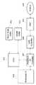
図1は本発明の実施の形態に係るネットワーク対応型デバイスのハードウエアの構成を示すブロック図である。ネットワーク対応型デバイスは、CPU301、フラッシュROM(Flash ROM)302、RAM303、LAN(Local Area Network)コントローラ(LAN Controller)304、LAN物理層制御部(PHY)305、コネクタ306、ペリフェラルインタフェースコントローラ(Peripheral Interface Controller)307、ペリフェラルインタフェース(Peripheral Interface)308を備えている。
【0023】
上記構成を詳述すると、CPU301は、ネットワーク対応型デバイス各部を制御する中央処理装置であり、フラッシュROM302に格納されたプログラムコードに基づき図3・図4のフローチャートに示す処理を実行する。CPU301は、本ネットワーク対応型デバイスのアドレスを決定する決定手段である。本実施の形態では、CPU301は32bitRISC(Reduced Instruction Set Computer)チップを使用している。フラッシュROM302には、プログラムコード及びネットワーク管理情報データベーステーブルが保持されている。また、フラッシュROM302には、自動IPアドレス取得を実現するソフトウエアが格納されている。また、フラッシュROM302の一部領域をNon Volatileメモリ領域として使用し、ユーザが設定したパラメータ、コンフィグレーション(環境設定)情報等を記憶保持するのに利用している。このコンフィグレーション情報には、ネットワークに接続された他の装置のアドレスが含まれる。また、コンフィグレーション情報には、本ネットワーク対応型デバイスのアドレスが含まれる。
【0024】
RAM303は、DRAM(Dynamic RAM)として構成されており、作業領域として使用される。本実施の形態では、フラッシュROM302上に格納されたプログラム実行コード及びネットワーク管理情報データベーステーブルは、起動時にこのRAM303上にコピーされ、該コピー作業が完了した時点で上記プログラムコードの実行を開始する。このネットワーク管理情報データベーステーブルには、ネットワークに接続された他の装置のアドレスが含まれる。また、このネットワーク管理情報データベーステーブルには、本ネットワーク対応型デバイスのアドレスが含まれる。
【0025】
LANコントローラ304、LAN物理層制御部305は、コネクタ306を介して本ネットワーク対応型デバイスをイーサネット(R)に接続する。コネクタ306は、8ピンのモジュラージャック(RJ45−8)として構成されている。
【0026】
LANコントローラ304は、バス マスタ タイプを使用しており、送受信をイベントトリガとしてバス権をCPU301と調停し、CPU301とは独立して、RAM303上に確保されて送受信バッファ上のデータの送信/受信を実行する。LANコントローラ304は、ネットワークを介して他の装置と通信するための通信手段である。
【0027】
ペリフェラルI/Fコントローラ307は、不図示のペリフェラルと接続され、このペリフェラルとの間の通信を制御するASIC(Application Specified IC)であり、32KBのデュアルポートRAMを有する。
【0028】
ペリフェラルとは、前記デュアルポートRAMのメモリ領域を使用してデータを通信する。本実施の形態では、ペリフェラル装置としてプリンタを例に説明しているが、ペリフェラル装置(プリンタ)側のハード構成に関しては、本ネットワーク対応型デバイスと同様にCPU/ROM/RAMから構成されており、通信制御部側の制御系からは独立した構成を持つ(図示は省略する)。
【0029】
図2は本発明の実施の形態に係るネットワーク対応型デバイスのソフトウエアの構成を示すブロック図である。ネットワーク対応型デバイスは、イーサネット(R)ドライバ(Ethernet(R)Driver)1、TCP/UDP/IPプロトコルスタック(Transmission Control Protocol/User Datagram Protocol/Internet Protocol)2、HTTP(Hyper Text Transfer Protocol)3、自動IPアドレス取得処理部(Auto IP)4、ARP(Address Resolution Protocol)5、プリントプロトコルモジュール(Print Protocol Module)6、プリンタコントローラ(Printer Controller)7を備えている。
【0030】
上記構成を詳述すると、本実施の形態では、ネットワーク対応型デバイスはプリンタとして構成されている。ネットワーク対応型デバイスは、通信機能としてイーサネット(R)ドライバ1上に、TCP/UDP/IPプロトコルスタック2を備えており、該TCP/UDP/IPプロトコルスタック2上に、HTTP1.1サーバの機能(HTTP3)を実装し、該HTTP1.1サーバ(HTTP3)を介してデバイスのコンフィグレーション、ステータスの取得などのサービスを提供する。
【0031】
自動IPアドレス取得処理部4は、ネットワークドライバ層の上位層に実装され、更に、自動IPアドレス取得処理部4は、ARP5の上位層に実装されており、後述のARPプローブパケット、ARPパケットの送受信の制御を実行する。
【0032】
また、TCP/UDP/IPプロトコルスタック2上には、プリントプロトコルモジュール6が実装されており、LAN8に接続されたクライアントから発行されるプリント要求を解析し、プリンタコントローラ7に対し該プリント要求を送出する機能を備えている。
【0033】
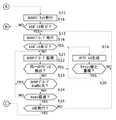
次に、上記の如く構成されたネットワーク対応型デバイスの動作について図3・図4のフローチャートを参照しながら詳細に説明する。図3・図4のフローチャートに示す処理は、ネットワーク対応型デバイスのCPU301がフラッシュROM302に格納されたプログラムコードに基づき実行する。
【0034】
ネットワーク対応型デバイスは、起動後、不揮発メモリ(フラッシュROM302)上のNon Volatile RAM領域に記録された該ネットワーク対応型デバイスのIPアドレスをチェックする(ステップS1)。不揮発メモリ上に記録されたネットワーク対応型デバイスのIPアドレス値が0.0.0.0である場合(即ち、ネットワーク対応型デバイスが以前に使用したIPアドレス値が記録されていない場合)、ネットワーク対応型デバイスが全く新規にネットワークに接続され使用される場合であり(ステップS2でyes)、自動IPアドレス取得手順(draft-ietf-zeroconf-ipv4-linklocal-01.txt)に従い、IANA(Internet Assigned Number Authority:インターネットアドレス管理機構)に登録されている自動IPアドレスレンジ169.254.1.0〜169.254.254.255より、一つのIPアドレスを選択(生成)する。
【0035】
本実施の形態において、上記のIPアドレス生成においては、下位3バイトに対し0〜255までの乱数を生成して、候補となるIPアドレスを生成する(ステップS3)。この場合、乱数の生成においては、ネットワーク対応型デバイス自身のMAC(Media Access Control)アドレスの最下位バイト値と、ネットワーク対応型デバイスの起動時からの積算時間との積を核として使用する。
【0036】
次に、上記ステップS3で生成したIPアドレスが、既にネットワーク上で稼動している他のデバイスに使用されているか否かをチェックするために、ターゲットIPアドレスに上記ステップS3で生成したIPアドレスをセットし、発信元アドレスをネットワーク対応型デバイス自身の物理アドレスにセットし、発信元IPアドレスには0.0.0.0をセットしたARPプローブパケットを発行する(ステップS4)。また、それと同時に内部タイマをゼロクリアする。
【0037】
ARPプローブパケットに対し応答があった場合(ステップS5でyes)、上記ステップS3において生成したIPアドレスは、既にネットワーク上で稼動している他のデバイスに使用されていることを意味するので、再度、上記ステップS3において候補となるIPアドレス生成を実行し、ステップS4以降の処理を実行する。
【0038】
ARPプローブパケットに対し応答が無かった場合は(ステップS5でno)、他のデバイスから発行されるARPプローブパケットの有無を監視する(ステップS6)。ARPプローブパケットを受信し、且つARPプローブパケットのターゲットIPアドレスの値が、上記ステップS3で生成したIPアドレスと同一であった場合は(ステップS7でyes)、ネットワーク上で稼動を開始した他のデバイスとのIPアドレスがコンフリクトする可能性あるので、上記ARPプローブパケットに対しては応答せず、上記ステップ3の手順に戻り、再度、候補となるIPアドレスを生成し、上記ステップ3以降の処理を実行する。
【0039】
本実施の形態においては、上記自動IPアドレス取得手順(draft-ietf-zeroconf-ipv4-linklocal-01.txt)記載の推奨に従い、ステップS4からステップS7までの検証を4秒間隔で3回繰り返すが、本実施の形態では、以下の手順に従い、ネットワーク上のARPプローブパケットのトラフィックに応じ再検証のインターバルを調整する。
【0040】
上記ステップ6においてIPアドレスのコンフリクトが検出されない場合、次に1秒あたりのARPプローブのパケット受信数を計測する。ARPプローブパケットの受信数が50パケット/secを超える場合は、例えば停電後の同時復旧など、ネットワーク上のデバイスが一斉に自動IPアドレス取得のプロセスを実行することによるトラフィック増加を意味するものであり、本実施の形態においては、ARPプローブパケットの受信数が10パケット/sec以下になるまでARPプローブパケットの監視を継続する(ステップS8)。これにより、ネットワーク上のトラフィックの低減を実現する。ARPプローブパケットの受信数が10パケット/sec以下であり、且つネットワーク対応型デバイス自身がARPプローブを発行してから4秒経過した場合は(ステップS9でyes)、上記ステップS4に戻り、再度、ARPプローブを発行する。
【0041】
以上のステップS4〜ステップS7を3回繰り返すことで(ステップS10でyes)、ネットワーク上の他のデバイスとIPアドレスのコンフリクトが無いことが確認されるので、ネットワーク上に送信先/送信元ともに、ネットワーク対応型デバイス自身の物理アドレス、IPアドレスをセットしたGratuitous ARPパケットを発行し、ネットワーク上の他のデバイスに対しARPキャッシュの更新を促す(ステップS11)。以上の処理が完了した後、ネットワーク対応型デバイス自身のIPアドレスを確定し(ステップS12)、確定したネットワーク対応型デバイス自身のIPアドレスを不揮発メモリ(フラッシュROM302)上に記憶する(ステップS13)。
【0042】
また、以降は、ネットワーク上の他のデバイスが発行したGratuitous ARPパケットを受信すると、そのGratuitous ARPパケットにセットされた他のデバイスの物理アドレス、IPアドレスにより、DRAM303のARPキャッシュの内容を常時更新するとともに、該更新内容を同様に不揮発メモリ(フラッシュROM302)上に記憶する(ステップS14)。
【0043】
以後、IPを使用する上位アプリケーションは該IPアドレスを使用し、各サービスの実行を行う。
【0044】
上記ステップS1において不揮発メモリ(フラッシュROM302)上に記録されているIPアドレス値が0.0.0.0以外の場合、即ち、ネットワーク対応型デバイスが以前に使用したIPアドレス値が記録されている場合(ステップS2でno)、まず、ネットワーク対応型デバイスが現在接続されているネットワークセグメントが、前回接続されていたネットワークセグメントと同一か否かを確認するために、不揮発メモリ(フラッシュROM302)上に記録されたARPキャッシュの内容を元に、ARPパケットを発行する。ARPキャッシュには、ネットワークに接続された他のデバイスの物理アドレス、IPアドレスが記憶されている。ARPパケットを発行する際は、IPアドレスの最上位バイトが162以外、即ち、自動IPアドレス取得を使用しておらず、IPアドレスが変更される可能性の低いデバイスに対してARPパケットを発行し、そのIPアドレスを有するデバイスがネットワーク上に存在するか否かを確認する(ステップS15)。
【0045】
ARPパケットに対する応答が得られなかった場合は(ステップS16でno)、ネットワーク対応型デバイスは前回接続されていたネットワークセグメントとは異なるネットワークセグメントに接続されたものと判断し、新規にIPアドレスを取得する必要があるので、上記ステップS3からステップS14までのプロセスを実行する。
【0046】
ARPパケットに対する応答が得られた場合は(ステップS16でyes)、ネットワーク対応型デバイスは前回接続されていたネットワークセグメントと同一のネットワークセグメントに接続されていたものと判断し、この場合は、不揮発メモリ(フラッシュROM302)上に記憶されたIPアドレス、即ち、前回ネットワーク接続されていた際に使用していたIPアドレスを用い、該IPアドレスが既にネットワーク上で稼動している他のデバイスに使用されているか否かをチェックする。このチェックのために、ターゲットIPアドレスに該IPアドレスをセットし、発信元アドレスをネットワーク対応型デバイス自身の物理アドレスにセットし、発信元IPアドレスには0.0.0.0をセットしたARPプローブパケットを発行する。また、それと同時に内部タイマをゼロクリアする(ステップS17)。
【0047】
ARPプローブパケットに対し応答があった場合は(ステップS18でyes)、該IPアドレスは、既にネットワーク上で稼動している他のデバイスに使用されていることを意味する。この場合は、上記ステップS3と同一の手順で候補となるIPアドレスを生成するが(ステップS19)、該生成したIPアドレス値が不揮発メモリ(フラッシュROM302)上に記憶されたARPキャッシュに記憶された内容(ネットワークに接続された他のデバイスIPアドレス)と同一の場合は(ステップS20でyes)、再度、別のIPアドレスを生成し、既にネットワーク上で稼動しているデバイスのIPアドレスとのコンフリクトの可能性を低減させる。
【0048】
ARPプローブパケットに対し応答が無かった場合は(ステップS18でno)、他のデバイスから発行されるARPプローブパケットの有無を監視する(ステップS21)。ARPプローブパケットを受信し、且つARPプローブパケットのターゲットIPアドレスの値がネットワーク対応型デバイス自身のIPアドレスと同一であった場合(ステップS22でyes)、ネットワーク上で稼動を開始した他のデバイスとのIPアドレスがコンフリクトする可能性あるので、ARPプローブパケットに対しては応答せず、再度、候補となるIPアドレスを生成し(ステップS19)、ステップS17以降の処理を実行する。
【0049】
本実施の形態においては、上記自動IPアドレス取得手順(draft-ietf-zeroconf-ipv4-linklocal-01.txt)記載の推奨に従い、ステップS21からステップS22までの検証を4秒間隔で3回繰り返すが、本実施の形態では、以下の手順に従い、ネットワーク上のARPプローブのトラフィックに応じ再検証のインターバルを調整する。
【0050】
上記ステップ21においてIPアドレスのコンフリクトが検出されない場合、次に1秒あたりのARPプローブのパケット受信数を計測する。ARPプローブパケットの受信数が50パケット/secを超える場合は、例えば停電後の同時復旧など、ネットワーク上のデバイスが一斉に自動IPアドレス取得のプロセスを実行することによるトラフィック増加を意味するものであり、本実施の形態においては、ARPプローブパケットの受信数が10パケット/sec以下になるまでARPプローブパケットの監視を継続する(ステップS23)。これにより、ネットワーク上のトラフィックの低減を実現する。ARPプローブパケットの受信数が10パケット/sec以下であり、且つネットワーク対応型デバイス自身の発行したARPプローブが4秒経過した場合は(ステップS24でyes)、ステップS17に戻り、再度、ARPプローブを発行する。
【0051】
以上のステップS17〜ステップS24を3回繰り返した後(ステップS25)、ステップS11へ進む。
【0052】
本実施の形態では、ネットワーク対応型デバイスとしてプリンタを例に挙げた場合を示しているが、ネットワーク対応型デバイスとしては、スキャナ、ファクシミリ、複写機、それらを複合した機能(画像読取機能、ファクシミリ機能、画像形成機能)を備えた複合機、デジタルカメラ等の画像処理装置、或いは画像処理装置に限らず情報を処理する装置に適用することが可能であり、この種の装置であれば、いずれの場合においても本発明を実現することが可能である。
【0053】
また、本実施の形態では、新規IPアドレスを生成する度に乱数生成アルゴリズムを使用しているが、一度IPアドレスを生成した後にコンフリクトを検出し、再度IPアドレスを生成する際は、単純に、最初に生成したIPアドレスに特定値を加算或いは減算するような他の処理手順を採用することでも、本発明を実現することが可能である。
【0054】
また、本実施の形態では、ARPプローブを4秒間隔で3回発行することで、他のデバイスとのIPアドレスのコンフリクトの有無を確認しているが、これらの値は、上記の例に限定されるものではなく、また、これらの値を固定値ではなく、ネットワーク対応型デバイスの操作パネル、或いはネットワーク対応型デバイスに実装されたHTTPサーバ等を介して設定変更することも可能である。
【0055】
同様に、ARPプローブのトラフィックの計測における単位時間あたりのパケット数に関しても、上記の例に限定されるものではなく、設定変更を可能とする実施形態を採ることも可能である。
【0056】
また、本実施の形態では、ネットワークに接続された他のネットワーク対応型デバイスのMACアドレスとIPアドレスの情報としてARPキャッシュの内容を不揮発メモリ(フラッシュROM302)上に記憶しているが、他の実施形態では、Microsoftが主催するUniversal Plug and Play Device Architecture1.0で規定されるGENA(General Event Notification Architecture) Notifyパケットを監視し、該パケットのLOCATIONヘッダから他のネットワーク対応型デバイスのIPアドレスを、UUIDヘッダからMACアドレスを取得し、受信した全てのNotifyパケットからネットワーク上に存在し、且つNotifyパケットの発行が可能なネットワークデバイスのMACアドレスとIPアドレスの情報を不揮発メモリ上に記憶する。
【0057】
また、他の実施形態では、ARPプローブのトラフィックと連動して、他のデバイスから発行される単位時間当たりのプローブパケット数に応じて、自身のARPプローブ発行の間隔/発行回数を変化させる。
【0058】
また、他の実施形態では、フラッシュROM302に、第1のネットワーク用のARPキャッシュ及びネットワーク対応型デバイス自身の第1のIPアドレスと、第2のネットワーク用のARPキャッシュ及びネットワーク対応型デバイス自身の第2のIPアドレスを記憶する。そして、第1のネットワーク用のARPキャッシュに含まれるIPアドレスを有するデバイスがネットワーク上に存在する場合、ネットワーク対応型デバイス自身のIPアドレスとして、第1のIPアドレスを用いる。また、第2のネットワーク用のARPキャッシュに含まれるIPアドレスを有するデバイスがネットワーク上に存在する場合、ネットワーク対応型デバイス自身のIPアドレスとして、第2のIPアドレスを用いる。
【0059】
尚、本発明は、複数の機器から構成されるシステムに適用しても、1つの機器からなる装置に適用してもよい。上述した実施形態の機能を実現するソフトウエアのプログラムコードを記憶した記憶媒体等の媒体をシステム或いは装置に供給し、そのシステム或いは装置のコンピュータ(またはCPUやMPU)が記憶媒体等の媒体に格納されたプログラムコードを読み出し実行することによっても、本発明は実現可能である。
【0060】
この場合、記憶媒体等の媒体から読み出されたプログラムコード自体が上述した実施形態の機能を実現することになり、そのプログラムコードを記憶した記憶媒体等の媒体は本発明を構成することになる。プログラムコードを供給するための記憶媒体等の媒体としては、例えば、フロッピー(登録商標)ディスク、ハードディスク、光ディスク、光磁気ディスク、CD−ROM、CD−R、CD−RW、DVD−ROM、DVD−RAM、DVD−RW、DVD+RW、磁気テープ、不揮発性のメモリカード、ROM、或いはネットワークを介したダウンロードなどを用いることができる。
【0061】
また、コンピュータが読み出したプログラムコードを実行することにより、上述した実施形態の機能が実現されるだけでなく、そのプログラムコードの指示に基づき、コンピュータ上で稼動しているOSなどが実際の処理の一部または全部を行い、その処理によって上述した実施形態の機能が実現される場合も、本発明に含まれる。
【0062】
更に、記憶媒体等の媒体から読み出されたプログラムコードが、コンピュータに挿入された機能拡張ボードやコンピュータに接続された機能拡張ユニットに備わるメモリに書き込まれた後、そのプログラムコードの指示に基づき、その機能拡張ボードや機能拡張ユニットに備わるCPUなどが実際の処理の一部または全部を行い、その処理によって上述した実施形態の機能が実現される場合も、本発明に含まれる。
【0063】
【発明の効果】
以上説明したように、本発明によれば、アドレスが他のデバイスとコンフリクトする可能性を低下させることができる。
【0064】
また、本発明によれば、トラフィックを低減させることができる。
【0065】
また、本発明によれば、デバイスを利用するクライアント側アプリケーションの設定変更の必要性を低減することができる。
【図面の簡単な説明】
【図1】本発明の実施の形態に係るネットワーク対応型デバイスのハードウエアの構成を示すブロック図である。
【図2】図1に示すネットワーク対応型デバイスのソフトウエアの構成を示すブロック図である。
【図3】図1に示すネットワーク対応型デバイスにおける処理を示すフローチャートである。
【図4】図3のフローチャートの続きである。
【符号の説明】
301 CPU(決定手段)
302 フラッシュROM(メモリ手段)
303 RAM
304 LANコントローラ
305 LAN物理層制御部
307 ペリフェラルI/Fコントローラ(通信手段)
308 ペリフェラルI/F[0001]
BACKGROUND OF THE INVENTION
The present invention relates to a device connected to a network, an address determination program, and an address determination method.
[0002]
[Prior art]
2. Description of the Related Art With the rapid spread of communication over the Internet, network-compatible devices have been changed from conventional personal computers to user interactive devices such as PDAs (Personal Digital Assistance) and mobile phones, scanners, printers, copiers, Network support is rapidly progressing from home appliances such as image processing devices such as digital cameras, televisions, air conditioners and refrigerators.
[0003]
Along with this, the network connection procedure of network-compatible devices, which has been conventionally performed under the network administrator, has been simplified. For IP address settings that are particularly important for Internet Protocol (IP) settings, IP addresses are automatically assigned using a DHCP (Dynamic Host Configuration Protocol) server, or SOHO (Small Office / Home). For network environments where server installation cannot be expected, such as an Office environment, automatic IP address acquisition (draft-ietf-zeroconf-ipv4-linklocal-01.txt) has been proposed (for example, Non-Patent Document 1). reference.). The above-mentioned automatic IP address acquisition is also adopted in Universal Plug and Play Device Architecture v1.0 sponsored by Microsoft. As a result, general users can use the network-compatible devices listed above without being bothered by the IP address setting rules and management.
[0004]
[Non-Patent Document 1]
Internet <URL: http://www.upnp.org/download/draft -ietf-zeroconf-ipv4-linklocal-01-Apr.txt>
[0005]
[Problems to be solved by the invention]
However, the above prior art has the following problems.
[0006]
In other words, as recommended in the above automatic IP address acquisition (draft-ietf-zeroconf-ipv4-linklocal-01.txt), if a network compatible device implements an algorithm for IP address acquisition, The device executes a process of obtaining a new IP address every time it is activated. However, when an accident such as a power outage occurs in an environment where network-compatible devices are connected on the network, for example, in the tens of units, or when the devices are started all at once after the start of work, etc. When a large number of devices acquire IP addresses all at once using a specified algorithm, network traffic is generated on the network by ARP (Address Resolution Protocol) packets for address confirmation, and the ARP response wait time Depending on the setting, there may be a conflict (collision) of the IP address.
[0007]
In addition, when there is no dynamic DNS (Domain Name Service: a distributed name list management system for the Internet that associates an IP address and a domain name) on the network, a client using these network-compatible services is not a host name but an IP address. It is necessary to communicate using. Therefore, every time the IP address of the network compatible device changes, it is necessary to change the setting of the client side application.
[0008]
The first object of the present invention is to reduce the possibility of an address conflict with another device.
[0009]
The second object of the present invention is to reduce traffic.
[0010]
A third object of the present invention is to reduce the necessity of changing the setting of a client-side application that uses a device.
[0012]
[Means for Solving the Problems]
In order to achieve the above object, a device connected to the network of the present invention includes a communication means for communicating with another device via the network, a determining means for determining its own address, its own address and other devices. Memory means for storing an address, and the determining means determines whether or not a device using the address of another device stored in the memory means exists on the network, and the device If it exists, it is decided to reuse its own address stored in the memory means.
[0014]
In order to achieve the above object, the address determination program of the present invention uses its own address and the address of another device.MemoryDoMemoryFunction andMemoryIn functionMemoryA determination function for determining whether or not a device using the address of the other device is present on the network, and if the device exists,MemoryIn functionMemoryIt is characterized in that a computer realizes a reuse function for reusing a registered address.
[0016]
In order to achieve the above object, the address determination method of the present invention uses its own address and the address of another device.MemoryDoMemoryStep and saidMemoryIn stepsMemoryA determination step of determining whether or not a device using the address of the other device is present on the network; and if the device is present,MemoryIn stepsMemoryAnd a reuse step for reusing the address of the user.
[0017]
DETAILED DESCRIPTION OF THE INVENTION
First, an outline will be described before describing the details of the embodiment of the present invention.
[0018]
In the embodiment of the present invention, the network compatible device having the configuration shown in FIG. 1 generates an IP address, and whether or not the generated IP address competes with other network compatible devices connected to the network. The IP address is generated until no conflict is recognized, the IP address for which the conflict is not recognized is adopted as the IP address of the network compatible device itself, and the adopted IP address and other network compatible types are used. Store the physical address and IP address of the device.
[0019]
In the embodiment of the present invention, the network compatible device checks whether or not the currently connected network segment is the same network segment as the previously connected network segment. In some cases, the first candidate IP address is the adopted IP address, and the second and subsequent candidate IP addresses are different by excluding the stored IP addresses of other network compatible devices. If it is a network segment, a candidate IP address is generated by random number generation within a predetermined range.
[0020]
In the embodiment of the present invention, the network compatible device issues a packet for confirming whether or not it competes with another network compatible device, and monitors the packet issued by the other network compatible device. If the traffic per unit time of the received packet exceeds a predefined value, the packet for checking whether or not it competes with other network compatible devices until the traffic drops to the predefined value Stop issuing.
[0021]
Hereinafter, embodiments of the present invention will be described in detail with reference to the drawings.
[0022]
FIG. 1 is a block diagram showing a hardware configuration of a network compatible device according to an embodiment of the present invention. The network compatible device includes a
[0023]
In detail, the
[0024]
The
[0025]
The
[0026]
The
[0027]
The peripheral I /
[0028]
The peripheral communicates data using the memory area of the dual port RAM. In this embodiment, a printer is described as an example of the peripheral device. However, the hardware configuration on the peripheral device (printer) side is composed of a CPU / ROM / RAM as in this network-compatible device. It has a configuration independent from the control system on the communication control unit side (not shown).
[0029]
FIG. 2 is a block diagram showing a software configuration of the network compatible device according to the embodiment of the present invention. The network compatible device includes an Ethernet (R)
[0030]
In detail, in the present embodiment, the network-compatible device is configured as a printer. The network-compatible device includes a TCP / UDP /
[0031]
The automatic IP address
[0032]
A
[0033]
Next, the operation of the network-compatible device configured as described above will be described in detail with reference to the flowcharts of FIGS. The processing shown in the flowcharts of FIGS. 3 and 4 is executed by the
[0034]
After starting up, the network compatible device checks the IP address of the network compatible device recorded in the Non Volatile RAM area on the nonvolatile memory (flash ROM 302) (step S1). When the IP address value of the network compatible device recorded on the nonvolatile memory is 0.0.0.0 (that is, when the IP address value previously used by the network compatible device is not recorded), the network This is a case in which a compatible device is newly connected to the network and used (yes in step S2). According to the automatic IP address acquisition procedure (draft-ietf-zeroconf-ipv4-linklocal-01.txt), IANA (Internet Assigned One IP address is selected (generated) from the automatic IP address range 169.254.4.1 to 169.254.254.255 registered in the Number Authority (Internet Address Management Organization).
[0035]
In this embodiment, in the above IP address generation, random numbers from 0 to 255 are generated for the lower 3 bytes, and candidate IP addresses are generated (step S3). In this case, in the generation of random numbers, the product of the least significant byte value of the MAC (Media Access Control) address of the network compatible device itself and the accumulated time from the start of the network compatible device is used as a core.
[0036]
Next, in order to check whether the IP address generated in step S3 is being used by another device already operating on the network, the IP address generated in step S3 is set as the target IP address. The ARP probe packet in which the source address is set to the physical address of the network-compatible device itself and 0.0.0.0 is set to the source IP address is issued (step S4). At the same time, the internal timer is cleared to zero.
[0037]
If there is a response to the ARP probe packet (yes in step S5), it means that the IP address generated in step S3 is already used by another device operating on the network. In step S3, a candidate IP address is generated, and the processes in and after step S4 are executed.
[0038]
If there is no response to the ARP probe packet (no in step S5), the presence or absence of an ARP probe packet issued from another device is monitored (step S6). When the ARP probe packet is received and the value of the target IP address of the ARP probe packet is the same as the IP address generated in the above step S3 (yes in step S7), the other operation started on the network Since there is a possibility that the IP address with the device may conflict, the process does not respond to the ARP probe packet, returns to the procedure of
[0039]
In this embodiment, the verification from step S4 to step S7 is repeated three times at 4-second intervals in accordance with the recommendation described in the automatic IP address acquisition procedure (draft-ietf-zeroconf-ipv4-linklocal-01.txt). In this embodiment, the revalidation interval is adjusted according to the traffic of the ARP probe packet on the network according to the following procedure.
[0040]
If no IP address conflict is detected in
[0041]
By repeating the above steps S4 to S7 three times (yes in step S10), it is confirmed that there is no IP address conflict with other devices on the network. A Gratuitous ARP packet in which the physical address and IP address of the network-compatible device itself are set is issued to prompt other devices on the network to update the ARP cache (step S11). After the above processing is completed, the IP address of the network compatible device itself is determined (step S12), and the determined IP address of the network compatible device itself is stored in the nonvolatile memory (flash ROM 302) (step S13).
[0042]
Further, after that, when a Gratuitous ARP packet issued by another device on the network is received, the contents of the ARP cache of the
[0043]
Thereafter, the host application using the IP uses the IP address to execute each service.
[0044]
When the IP address value recorded on the nonvolatile memory (flash ROM 302) in step S1 is other than 0.0.0.0, that is, the IP address value previously used by the network compatible device is recorded. In the case (no in step S2), first, in order to confirm whether or not the network segment to which the network-compatible device is currently connected is the same as the network segment to which the previous connection was made, it is stored on the nonvolatile memory (flash ROM 302). An ARP packet is issued based on the recorded contents of the ARP cache. The ARP cache stores physical addresses and IP addresses of other devices connected to the network. When issuing the ARP packet, the most significant byte of the IP address is other than 162, that is, the automatic IP address acquisition is not used, and the ARP packet is issued to a device that is unlikely to change the IP address. Then, it is confirmed whether or not a device having the IP address exists on the network (step S15).
[0045]
If no response to the ARP packet is obtained (no in step S16), the network compatible device determines that it is connected to a network segment different from the previously connected network segment, and obtains a new IP address. Therefore, the processes from step S3 to step S14 are executed.
[0046]
When a response to the ARP packet is obtained (yes in step S16), the network compatible device determines that it is connected to the same network segment as the previously connected network segment, and in this case, the nonvolatile memory The IP address stored on the (flash ROM 302), that is, the IP address used when it was connected to the network last time, is used by another device already operating on the network. Check whether it exists. For this check, the target IP address is set to the IP address, the source address is set to the physical address of the network compatible device itself, and the source IP address is set to 0.0.0.0. Issue a probe packet. At the same time, the internal timer is cleared to zero (step S17).
[0047]
If there is a response to the ARP probe packet (yes in step S18), it means that the IP address is already used by another device operating on the network. In this case, a candidate IP address is generated in the same procedure as in step S3 (step S19), but the generated IP address value is stored in the ARP cache stored in the nonvolatile memory (flash ROM 302). If the content (the IP address of another device connected to the network) is the same (yes in step S20), another IP address is generated again, and there is a conflict with the IP address of a device already operating on the network. Reduce the possibility of
[0048]
If there is no response to the ARP probe packet (no in step S18), the presence / absence of an ARP probe packet issued from another device is monitored (step S21). When the ARP probe packet is received and the value of the target IP address of the ARP probe packet is the same as the IP address of the network-compatible device itself (yes in step S22), with other devices that have started operation on the network Therefore, the IP address that is a candidate is generated again (step S19), and the processes after step S17 are executed.
[0049]
In the present embodiment, the verification from step S21 to step S22 is repeated three times at 4-second intervals in accordance with the recommendation described in the automatic IP address acquisition procedure (draft-ietf-zeroconf-ipv4-linklocal-01.txt). In this embodiment, the revalidation interval is adjusted according to the traffic of the ARP probe on the network according to the following procedure.
[0050]
If no IP address conflict is detected in
[0051]
After step S17 to step S24 are repeated three times (step S25), the process proceeds to step S11.
[0052]
In this embodiment, a printer is taken as an example of a network-compatible device. However, the network-compatible device includes a scanner, a facsimile, a copying machine, and a function that combines them (image reading function, facsimile function). , An image processing apparatus such as a multi-function peripheral equipped with an image forming function), a digital camera, or an image processing apparatus, and can be applied to any apparatus that processes information. Even in this case, the present invention can be realized.
[0053]
In this embodiment, a random number generation algorithm is used every time a new IP address is generated. However, when an IP address is generated once and a conflict is detected and an IP address is generated again, simply, The present invention can also be realized by adopting another processing procedure such as adding or subtracting a specific value to the IP address generated first.
[0054]
In this embodiment, the presence or absence of an IP address conflict with another device is confirmed by issuing the ARP probe three times at intervals of 4 seconds. However, these values are limited to the above example. In addition, these values are not fixed values, and it is also possible to change the setting via an operation panel of the network compatible device, an HTTP server mounted on the network compatible device, or the like.
[0055]
Similarly, the number of packets per unit time in the measurement of the traffic of the ARP probe is not limited to the above example, and it is also possible to adopt an embodiment that enables setting change.
[0056]
In this embodiment, the contents of the ARP cache are stored on the nonvolatile memory (flash ROM 302) as the MAC address and IP address information of other network compatible devices connected to the network. In the form, a General Event Notification Architecture (GENA) Notify packet defined by Universal Plug and Play Device Architecture 1.0 sponsored by Microsoft is monitored, and the IP address of another network-compatible device is assigned from the LOCATION header of the packet to the UUID. The MAC address is acquired from the header, and the MAC address and IP address information of the network device that exists on the network from all the received Notify packets and can issue the Notify packet is stored in the nonvolatile memory.
[0057]
In another embodiment, the ARP probe issuance interval / issue count is changed according to the number of probe packets issued from other devices per unit time in conjunction with the ARP probe traffic.
[0058]
In another embodiment, the
[0059]
The present invention may be applied to a system composed of a plurality of devices or an apparatus composed of a single device. A medium such as a storage medium storing software program codes for realizing the functions of the above-described embodiments is supplied to the system or apparatus, and the computer (or CPU or MPU) of the system or apparatus stores the medium in the storage medium or the like. The present invention can also be realized by reading and executing the program code.
[0060]
In this case, the program code itself read from the medium such as a storage medium realizes the functions of the above-described embodiments, and the medium such as the storage medium storing the program code constitutes the present invention. . As a medium such as a storage medium for supplying the program code, for example, a floppy (registered trademark) disk, a hard disk, an optical disk, a magneto-optical disk, a CD-ROM, a CD-R, a CD-RW, a DVD-ROM, a DVD- RAM, DVD-RW, DVD + RW, magnetic tape, nonvolatile memory card, ROM, or download via a network can be used.
[0061]
Further, by executing the program code read out by the computer, not only the functions of the above-described embodiments are realized, but also the OS running on the computer based on the instruction of the program code performs the actual processing. A case where the functions of the above-described embodiment are realized by performing part or all of the processing is also included in the present invention.
[0062]
Furthermore, after the program code read from a medium such as a storage medium is written in a memory provided in a function expansion board inserted in the computer or a function expansion unit connected to the computer, based on the instruction of the program code, The present invention also includes the case where the CPU or the like provided in the function expansion board or function expansion unit performs part or all of the actual processing and the functions of the above-described embodiments are realized by the processing.
[0063]
【The invention's effect】
As described above, according to the present invention, the possibility of an address conflict with another device can be reduced.
[0064]
Further, according to the present invention, traffic can be reduced.
[0065]
Further, according to the present invention, it is possible to reduce the necessity of changing the setting of a client-side application that uses a device.
[Brief description of the drawings]
FIG. 1 is a block diagram showing a hardware configuration of a network-compatible device according to an embodiment of the present invention.
FIG. 2 is a block diagram showing a software configuration of the network compatible device shown in FIG. 1;
FIG. 3 is a flowchart showing processing in the network compatible device shown in FIG. 1;
FIG. 4 is a continuation of the flowchart of FIG.
[Explanation of symbols]
301 CPU (determination means)
302 Flash ROM (memory means)
303 RAM
304 LAN controller
305 LAN physical layer control unit
307 Peripheral I / F controller (communication means)
308 Peripheral I / F
Claims (9)
Translated fromJapanese前記決定手段は、前記メモリ手段に記憶された他の装置のアドレスを使用している装置がネットワーク上に存在するか否かを判断し、その装置が存在すれば、前記メモリ手段に記憶された自分のアドレスを再使用することを決定することを特徴とするネットワークに接続される装置。Communication means for communicating with other devices via a network, determination means for determining its own address, and memory means for storing its own address and the address of the other device,
The determining means determines whether or not a device using the address of another device stored in the memory means exists on the network. If the device exists, the determining means stores the device in the memory means. A device connected to a network characterized by deciding to reuse its own address.
Priority Applications (1)
| Application Number | Priority Date | Filing Date | Title |
|---|---|---|---|
| JP2003008444AJP3780259B2 (en) | 2002-01-22 | 2003-01-16 | Device connected to network, address determination program, and address determination method |
Applications Claiming Priority (3)
| Application Number | Priority Date | Filing Date | Title |
|---|---|---|---|
| JP2002-13088 | 2002-01-22 | ||
| JP2002013088 | 2002-01-22 | ||
| JP2003008444AJP3780259B2 (en) | 2002-01-22 | 2003-01-16 | Device connected to network, address determination program, and address determination method |
Publications (2)
| Publication Number | Publication Date |
|---|---|
| JP2003289317A JP2003289317A (en) | 2003-10-10 |
| JP3780259B2true JP3780259B2 (en) | 2006-05-31 |
Family
ID=29253079
Family Applications (1)
| Application Number | Title | Priority Date | Filing Date |
|---|---|---|---|
| JP2003008444AExpired - Fee RelatedJP3780259B2 (en) | 2002-01-22 | 2003-01-16 | Device connected to network, address determination program, and address determination method |
Country Status (1)
| Country | Link |
|---|---|
| JP (1) | JP3780259B2 (en) |
Families Citing this family (3)
| Publication number | Priority date | Publication date | Assignee | Title |
|---|---|---|---|---|
| CA2544014C (en)* | 2003-11-12 | 2015-07-14 | Nimcat Networks Inc. | Peer discovery |
| JP2006352714A (en)* | 2005-06-17 | 2006-12-28 | Fuji Electric Systems Co Ltd | Asymmetric network line multiplexer |
| JP4367400B2 (en)* | 2005-10-24 | 2009-11-18 | 日本電気株式会社 | Computer system, network device, failure occurrence notification method, and failure occurrence notification program |
- 2003
- 2003-01-16JPJP2003008444Apatent/JP3780259B2/ennot_activeExpired - Fee Related
Also Published As
| Publication number | Publication date |
|---|---|
| JP2003289317A (en) | 2003-10-10 |
Similar Documents
| Publication | Publication Date | Title |
|---|---|---|
| KR100544395B1 (en) | Network connection device, storage medium and address determination method | |
| KR101352852B1 (en) | Method for allocating IP address using DHCP in an image forming apparatus, Image forming apparatus thereof, and System for allocating IP address using DHCP | |
| US20080028071A1 (en) | Communication load reducing method and computer system | |
| US8745176B2 (en) | Method and device to set device configurations | |
| WO2003079642A2 (en) | A ddns server, a ddns client terminal and a ddns system, and a web server terminal, its network system and an access control method | |
| JP2002368763A (en) | Network device, server device, client device, network IP address assigning method and program | |
| US20070239860A1 (en) | Information processing device, network connection method, and program recording medium | |
| CN100576852C (en) | Method and device for obtaining internet protocol address | |
| US7577155B2 (en) | Printer with automatic acquisition and printing of network address | |
| US7827235B2 (en) | Service providing system, service providing method, and program of the same | |
| JP5882855B2 (en) | Method, system and program for protecting a host device | |
| EP2234015B1 (en) | Computer program for installing software | |
| JP3812285B2 (en) | Network system and network equipment | |
| US7916733B2 (en) | Data communication apparatus, data communication method, program, and storage medium | |
| JP5448527B2 (en) | Information processing apparatus, method thereof, and program | |
| JP3780259B2 (en) | Device connected to network, address determination program, and address determination method | |
| US20060047788A1 (en) | Information processing device, information processing method, and program | |
| JP5415354B2 (en) | Server apparatus, communication control method, and communication control program | |
| JP4745008B2 (en) | Client device, server device, and communication system | |
| KR100942719B1 (en) | Devices with Dynamic Host Configuration Protocol Snooping | |
| JP2002237816A (en) | Automatic address assignment method | |
| JP3856310B2 (en) | Device monitoring apparatus and device monitoring system | |
| JP5021001B2 (en) | Server apparatus, client apparatus, communication system, communication control method, and program | |
| JP2000222149A (en) | Printer address management apparatus and method | |
| KR100946162B1 (en) | Dynamic Host Configuration Protocol Server |
Legal Events
| Date | Code | Title | Description |
|---|---|---|---|
| A977 | Report on retrieval | Free format text:JAPANESE INTERMEDIATE CODE: A971007 Effective date:20050107 | |
| A131 | Notification of reasons for refusal | Free format text:JAPANESE INTERMEDIATE CODE: A131 Effective date:20050322 | |
| A521 | Written amendment | Free format text:JAPANESE INTERMEDIATE CODE: A523 Effective date:20050518 | |
| A131 | Notification of reasons for refusal | Free format text:JAPANESE INTERMEDIATE CODE: A131 Effective date:20050712 | |
| A02 | Decision of refusal | Free format text:JAPANESE INTERMEDIATE CODE: A02 Effective date:20051108 | |
| A521 | Written amendment | Free format text:JAPANESE INTERMEDIATE CODE: A523 Effective date:20051208 | |
| A521 | Written amendment | Free format text:JAPANESE INTERMEDIATE CODE: A523 Effective date:20060118 | |
| A911 | Transfer to examiner for re-examination before appeal (zenchi) | Free format text:JAPANESE INTERMEDIATE CODE: A911 Effective date:20060124 | |
| TRDD | Decision of grant or rejection written | ||
| A01 | Written decision to grant a patent or to grant a registration (utility model) | Free format text:JAPANESE INTERMEDIATE CODE: A01 Effective date:20060221 | |
| A61 | First payment of annual fees (during grant procedure) | Free format text:JAPANESE INTERMEDIATE CODE: A61 Effective date:20060306 | |
| R150 | Certificate of patent or registration of utility model | Ref document number:3780259 Country of ref document:JP Free format text:JAPANESE INTERMEDIATE CODE: R150 Free format text:JAPANESE INTERMEDIATE CODE: R150 | |
| FPAY | Renewal fee payment (event date is renewal date of database) | Free format text:PAYMENT UNTIL: 20100310 Year of fee payment:4 | |
| FPAY | Renewal fee payment (event date is renewal date of database) | Free format text:PAYMENT UNTIL: 20100310 Year of fee payment:4 | |
| FPAY | Renewal fee payment (event date is renewal date of database) | Free format text:PAYMENT UNTIL: 20110310 Year of fee payment:5 | |
| FPAY | Renewal fee payment (event date is renewal date of database) | Free format text:PAYMENT UNTIL: 20120310 Year of fee payment:6 | |
| FPAY | Renewal fee payment (event date is renewal date of database) | Free format text:PAYMENT UNTIL: 20130310 Year of fee payment:7 | |
| FPAY | Renewal fee payment (event date is renewal date of database) | Free format text:PAYMENT UNTIL: 20140310 Year of fee payment:8 | |
| LAPS | Cancellation because of no payment of annual fees |