JP3779674B2 - Distal tip for stem positioning of artificial joints - Google Patents
Distal tip for stem positioning of artificial jointsDownload PDFInfo
- Publication number
- JP3779674B2 JP3779674B2JP2002333193AJP2002333193AJP3779674B2JP 3779674 B2JP3779674 B2JP 3779674B2JP 2002333193 AJP2002333193 AJP 2002333193AJP 2002333193 AJP2002333193 AJP 2002333193AJP 3779674 B2JP3779674 B2JP 3779674B2
- Authority
- JP
- Japan
- Prior art keywords
- stem
- distal tip
- distal
- artificial joint
- distal end
- Prior art date
- Legal status (The legal status is an assumption and is not a legal conclusion. Google has not performed a legal analysis and makes no representation as to the accuracy of the status listed.)
- Expired - Fee Related
Links
- 210000000988bone and boneAnatomy0.000claimsdescription22
- 230000002093peripheral effectEffects0.000claimsdescription15
- 239000000463materialSubstances0.000claimsdescription10
- 238000003780insertionMethods0.000claimsdescription6
- 230000037431insertionEffects0.000claimsdescription6
- 239000004568cementSubstances0.000description11
- 208000003076OsteolysisDiseases0.000description9
- 208000029791lytic metastatic bone lesionDiseases0.000description9
- 210000000689upper legAnatomy0.000description8
- 230000000694effectsEffects0.000description5
- 230000000149penetrating effectEffects0.000description5
- 210000001503jointAnatomy0.000description4
- 238000000034methodMethods0.000description3
- 241001227561ValgusSpecies0.000description2
- 230000002745absorbentEffects0.000description2
- 239000002250absorbentSubstances0.000description2
- 210000001185bone marrowAnatomy0.000description2
- 229920001577copolymerPolymers0.000description2
- 210000004394hip jointAnatomy0.000description2
- 239000007769metal materialSubstances0.000description2
- 229920001432poly(L-lactide)Polymers0.000description2
- 238000001356surgical procedureMethods0.000description2
- JVTAAEKCZFNVCJ-REOHCLBHSA-NL-lactic acidChemical compoundC[C@H](O)C(O)=OJVTAAEKCZFNVCJ-REOHCLBHSA-N0.000description1
- 241001646593OsteocephalusSpecies0.000description1
- 229910001069Ti alloyInorganic materials0.000description1
- WAIPAZQMEIHHTJ-UHFFFAOYSA-N[Cr].[Co]Chemical class[Cr].[Co]WAIPAZQMEIHHTJ-UHFFFAOYSA-N0.000description1
- 238000010521absorption reactionMethods0.000description1
- 210000000544articulatio talocruralisAnatomy0.000description1
- 238000000354decomposition reactionMethods0.000description1
- 238000006073displacement reactionMethods0.000description1
- 210000002310elbow jointAnatomy0.000description1
- 210000001145finger jointAnatomy0.000description1
- 239000012530fluidSubstances0.000description1
- 210000002478hand jointAnatomy0.000description1
- 238000007913intrathecal administrationMethods0.000description1
- 210000000629knee jointAnatomy0.000description1
- 238000002156mixingMethods0.000description1
- 229920003023plasticPolymers0.000description1
- 210000000323shoulder jointAnatomy0.000description1
- 229910001220stainless steelInorganic materials0.000description1
- 239000010935stainless steelSubstances0.000description1
- 230000008685targetingEffects0.000description1
- 230000002747voluntary effectEffects0.000description1
Images


Classifications
- A—HUMAN NECESSITIES
- A61—MEDICAL OR VETERINARY SCIENCE; HYGIENE
- A61L—METHODS OR APPARATUS FOR STERILISING MATERIALS OR OBJECTS IN GENERAL; DISINFECTION, STERILISATION OR DEODORISATION OF AIR; CHEMICAL ASPECTS OF BANDAGES, DRESSINGS, ABSORBENT PADS OR SURGICAL ARTICLES; MATERIALS FOR BANDAGES, DRESSINGS, ABSORBENT PADS OR SURGICAL ARTICLES
- A61L27/00—Materials for grafts or prostheses or for coating grafts or prostheses
- A61L27/50—Materials characterised by their function or physical properties, e.g. injectable or lubricating compositions, shape-memory materials, surface modified materials
- A61L27/58—Materials at least partially resorbable by the body
- A—HUMAN NECESSITIES
- A61—MEDICAL OR VETERINARY SCIENCE; HYGIENE
- A61F—FILTERS IMPLANTABLE INTO BLOOD VESSELS; PROSTHESES; DEVICES PROVIDING PATENCY TO, OR PREVENTING COLLAPSING OF, TUBULAR STRUCTURES OF THE BODY, e.g. STENTS; ORTHOPAEDIC, NURSING OR CONTRACEPTIVE DEVICES; FOMENTATION; TREATMENT OR PROTECTION OF EYES OR EARS; BANDAGES, DRESSINGS OR ABSORBENT PADS; FIRST-AID KITS
- A61F2/00—Filters implantable into blood vessels; Prostheses, i.e. artificial substitutes or replacements for parts of the body; Appliances for connecting them with the body; Devices providing patency to, or preventing collapsing of, tubular structures of the body, e.g. stents
- A61F2/02—Prostheses implantable into the body
- A61F2/30—Joints
- A61F2/30721—Accessories
- A61F2/30724—Spacers for centering an implant in a bone cavity, e.g. in a cement-receiving cavity
- A—HUMAN NECESSITIES
- A61—MEDICAL OR VETERINARY SCIENCE; HYGIENE
- A61F—FILTERS IMPLANTABLE INTO BLOOD VESSELS; PROSTHESES; DEVICES PROVIDING PATENCY TO, OR PREVENTING COLLAPSING OF, TUBULAR STRUCTURES OF THE BODY, e.g. STENTS; ORTHOPAEDIC, NURSING OR CONTRACEPTIVE DEVICES; FOMENTATION; TREATMENT OR PROTECTION OF EYES OR EARS; BANDAGES, DRESSINGS OR ABSORBENT PADS; FIRST-AID KITS
- A61F2/00—Filters implantable into blood vessels; Prostheses, i.e. artificial substitutes or replacements for parts of the body; Appliances for connecting them with the body; Devices providing patency to, or preventing collapsing of, tubular structures of the body, e.g. stents
- A61F2/02—Prostheses implantable into the body
- A61F2/30—Joints
- A61F2/32—Joints for the hip
- A61F2/36—Femoral heads ; Femoral endoprostheses
- A61F2/3662—Femoral shafts
- A61F2/3676—Distal or diaphyseal parts of shafts
- A—HUMAN NECESSITIES
- A61—MEDICAL OR VETERINARY SCIENCE; HYGIENE
- A61F—FILTERS IMPLANTABLE INTO BLOOD VESSELS; PROSTHESES; DEVICES PROVIDING PATENCY TO, OR PREVENTING COLLAPSING OF, TUBULAR STRUCTURES OF THE BODY, e.g. STENTS; ORTHOPAEDIC, NURSING OR CONTRACEPTIVE DEVICES; FOMENTATION; TREATMENT OR PROTECTION OF EYES OR EARS; BANDAGES, DRESSINGS OR ABSORBENT PADS; FIRST-AID KITS
- A61F2/00—Filters implantable into blood vessels; Prostheses, i.e. artificial substitutes or replacements for parts of the body; Appliances for connecting them with the body; Devices providing patency to, or preventing collapsing of, tubular structures of the body, e.g. stents
- A61F2/02—Prostheses implantable into the body
- A61F2/30—Joints
- A61F2/32—Joints for the hip
- A61F2/36—Femoral heads ; Femoral endoprostheses
- A61F2/3662—Femoral shafts
- A61F2/367—Proximal or metaphyseal parts of shafts
- A—HUMAN NECESSITIES
- A61—MEDICAL OR VETERINARY SCIENCE; HYGIENE
- A61F—FILTERS IMPLANTABLE INTO BLOOD VESSELS; PROSTHESES; DEVICES PROVIDING PATENCY TO, OR PREVENTING COLLAPSING OF, TUBULAR STRUCTURES OF THE BODY, e.g. STENTS; ORTHOPAEDIC, NURSING OR CONTRACEPTIVE DEVICES; FOMENTATION; TREATMENT OR PROTECTION OF EYES OR EARS; BANDAGES, DRESSINGS OR ABSORBENT PADS; FIRST-AID KITS
- A61F2/00—Filters implantable into blood vessels; Prostheses, i.e. artificial substitutes or replacements for parts of the body; Appliances for connecting them with the body; Devices providing patency to, or preventing collapsing of, tubular structures of the body, e.g. stents
- A61F2/02—Prostheses implantable into the body
- A61F2/30—Joints
- A61F2/38—Joints for elbows or knees
- A61F2/3804—Joints for elbows or knees for elbows
- A—HUMAN NECESSITIES
- A61—MEDICAL OR VETERINARY SCIENCE; HYGIENE
- A61F—FILTERS IMPLANTABLE INTO BLOOD VESSELS; PROSTHESES; DEVICES PROVIDING PATENCY TO, OR PREVENTING COLLAPSING OF, TUBULAR STRUCTURES OF THE BODY, e.g. STENTS; ORTHOPAEDIC, NURSING OR CONTRACEPTIVE DEVICES; FOMENTATION; TREATMENT OR PROTECTION OF EYES OR EARS; BANDAGES, DRESSINGS OR ABSORBENT PADS; FIRST-AID KITS
- A61F2/00—Filters implantable into blood vessels; Prostheses, i.e. artificial substitutes or replacements for parts of the body; Appliances for connecting them with the body; Devices providing patency to, or preventing collapsing of, tubular structures of the body, e.g. stents
- A61F2/02—Prostheses implantable into the body
- A61F2/30—Joints
- A61F2/42—Joints for wrists or ankles; for hands, e.g. fingers; for feet, e.g. toes
- A61F2/4202—Joints for wrists or ankles; for hands, e.g. fingers; for feet, e.g. toes for ankles
- A—HUMAN NECESSITIES
- A61—MEDICAL OR VETERINARY SCIENCE; HYGIENE
- A61F—FILTERS IMPLANTABLE INTO BLOOD VESSELS; PROSTHESES; DEVICES PROVIDING PATENCY TO, OR PREVENTING COLLAPSING OF, TUBULAR STRUCTURES OF THE BODY, e.g. STENTS; ORTHOPAEDIC, NURSING OR CONTRACEPTIVE DEVICES; FOMENTATION; TREATMENT OR PROTECTION OF EYES OR EARS; BANDAGES, DRESSINGS OR ABSORBENT PADS; FIRST-AID KITS
- A61F2/00—Filters implantable into blood vessels; Prostheses, i.e. artificial substitutes or replacements for parts of the body; Appliances for connecting them with the body; Devices providing patency to, or preventing collapsing of, tubular structures of the body, e.g. stents
- A61F2/02—Prostheses implantable into the body
- A61F2/30—Joints
- A61F2/42—Joints for wrists or ankles; for hands, e.g. fingers; for feet, e.g. toes
- A61F2/4241—Joints for wrists or ankles; for hands, e.g. fingers; for feet, e.g. toes for hands, e.g. fingers
- A—HUMAN NECESSITIES
- A61—MEDICAL OR VETERINARY SCIENCE; HYGIENE
- A61F—FILTERS IMPLANTABLE INTO BLOOD VESSELS; PROSTHESES; DEVICES PROVIDING PATENCY TO, OR PREVENTING COLLAPSING OF, TUBULAR STRUCTURES OF THE BODY, e.g. STENTS; ORTHOPAEDIC, NURSING OR CONTRACEPTIVE DEVICES; FOMENTATION; TREATMENT OR PROTECTION OF EYES OR EARS; BANDAGES, DRESSINGS OR ABSORBENT PADS; FIRST-AID KITS
- A61F2/00—Filters implantable into blood vessels; Prostheses, i.e. artificial substitutes or replacements for parts of the body; Appliances for connecting them with the body; Devices providing patency to, or preventing collapsing of, tubular structures of the body, e.g. stents
- A61F2/02—Prostheses implantable into the body
- A61F2/30—Joints
- A61F2/42—Joints for wrists or ankles; for hands, e.g. fingers; for feet, e.g. toes
- A61F2/4261—Joints for wrists or ankles; for hands, e.g. fingers; for feet, e.g. toes for wrists
- A—HUMAN NECESSITIES
- A61—MEDICAL OR VETERINARY SCIENCE; HYGIENE
- A61F—FILTERS IMPLANTABLE INTO BLOOD VESSELS; PROSTHESES; DEVICES PROVIDING PATENCY TO, OR PREVENTING COLLAPSING OF, TUBULAR STRUCTURES OF THE BODY, e.g. STENTS; ORTHOPAEDIC, NURSING OR CONTRACEPTIVE DEVICES; FOMENTATION; TREATMENT OR PROTECTION OF EYES OR EARS; BANDAGES, DRESSINGS OR ABSORBENT PADS; FIRST-AID KITS
- A61F2/00—Filters implantable into blood vessels; Prostheses, i.e. artificial substitutes or replacements for parts of the body; Appliances for connecting them with the body; Devices providing patency to, or preventing collapsing of, tubular structures of the body, e.g. stents
- A61F2/02—Prostheses implantable into the body
- A61F2/30—Joints
- A61F2002/30001—Additional features of subject-matter classified in A61F2/28, A61F2/30 and subgroups thereof
- A61F2002/30003—Material related properties of the prosthesis or of a coating on the prosthesis
- A61F2002/3006—Properties of materials and coating materials
- A61F2002/30062—(bio)absorbable, biodegradable, bioerodable, (bio)resorbable, resorptive
- A—HUMAN NECESSITIES
- A61—MEDICAL OR VETERINARY SCIENCE; HYGIENE
- A61F—FILTERS IMPLANTABLE INTO BLOOD VESSELS; PROSTHESES; DEVICES PROVIDING PATENCY TO, OR PREVENTING COLLAPSING OF, TUBULAR STRUCTURES OF THE BODY, e.g. STENTS; ORTHOPAEDIC, NURSING OR CONTRACEPTIVE DEVICES; FOMENTATION; TREATMENT OR PROTECTION OF EYES OR EARS; BANDAGES, DRESSINGS OR ABSORBENT PADS; FIRST-AID KITS
- A61F2/00—Filters implantable into blood vessels; Prostheses, i.e. artificial substitutes or replacements for parts of the body; Appliances for connecting them with the body; Devices providing patency to, or preventing collapsing of, tubular structures of the body, e.g. stents
- A61F2/02—Prostheses implantable into the body
- A61F2/30—Joints
- A61F2002/30001—Additional features of subject-matter classified in A61F2/28, A61F2/30 and subgroups thereof
- A61F2002/30108—Shapes
- A61F2002/3011—Cross-sections or two-dimensional shapes
- A61F2002/30112—Rounded shapes, e.g. with rounded corners
- A61F2002/30113—Rounded shapes, e.g. with rounded corners circular
- A61F2002/30115—Rounded shapes, e.g. with rounded corners circular circular-O-shaped
- A—HUMAN NECESSITIES
- A61—MEDICAL OR VETERINARY SCIENCE; HYGIENE
- A61F—FILTERS IMPLANTABLE INTO BLOOD VESSELS; PROSTHESES; DEVICES PROVIDING PATENCY TO, OR PREVENTING COLLAPSING OF, TUBULAR STRUCTURES OF THE BODY, e.g. STENTS; ORTHOPAEDIC, NURSING OR CONTRACEPTIVE DEVICES; FOMENTATION; TREATMENT OR PROTECTION OF EYES OR EARS; BANDAGES, DRESSINGS OR ABSORBENT PADS; FIRST-AID KITS
- A61F2/00—Filters implantable into blood vessels; Prostheses, i.e. artificial substitutes or replacements for parts of the body; Appliances for connecting them with the body; Devices providing patency to, or preventing collapsing of, tubular structures of the body, e.g. stents
- A61F2/02—Prostheses implantable into the body
- A61F2/30—Joints
- A61F2002/30001—Additional features of subject-matter classified in A61F2/28, A61F2/30 and subgroups thereof
- A61F2002/30108—Shapes
- A61F2002/3011—Cross-sections or two-dimensional shapes
- A61F2002/30112—Rounded shapes, e.g. with rounded corners
- A61F2002/30113—Rounded shapes, e.g. with rounded corners circular
- A61F2002/30121—Rounded shapes, e.g. with rounded corners circular with lobes
- A—HUMAN NECESSITIES
- A61—MEDICAL OR VETERINARY SCIENCE; HYGIENE
- A61F—FILTERS IMPLANTABLE INTO BLOOD VESSELS; PROSTHESES; DEVICES PROVIDING PATENCY TO, OR PREVENTING COLLAPSING OF, TUBULAR STRUCTURES OF THE BODY, e.g. STENTS; ORTHOPAEDIC, NURSING OR CONTRACEPTIVE DEVICES; FOMENTATION; TREATMENT OR PROTECTION OF EYES OR EARS; BANDAGES, DRESSINGS OR ABSORBENT PADS; FIRST-AID KITS
- A61F2/00—Filters implantable into blood vessels; Prostheses, i.e. artificial substitutes or replacements for parts of the body; Appliances for connecting them with the body; Devices providing patency to, or preventing collapsing of, tubular structures of the body, e.g. stents
- A61F2/02—Prostheses implantable into the body
- A61F2/30—Joints
- A61F2002/30001—Additional features of subject-matter classified in A61F2/28, A61F2/30 and subgroups thereof
- A61F2002/30108—Shapes
- A61F2002/3011—Cross-sections or two-dimensional shapes
- A61F2002/30138—Convex polygonal shapes
- A61F2002/30146—Convex polygonal shapes octagonal
- A—HUMAN NECESSITIES
- A61—MEDICAL OR VETERINARY SCIENCE; HYGIENE
- A61F—FILTERS IMPLANTABLE INTO BLOOD VESSELS; PROSTHESES; DEVICES PROVIDING PATENCY TO, OR PREVENTING COLLAPSING OF, TUBULAR STRUCTURES OF THE BODY, e.g. STENTS; ORTHOPAEDIC, NURSING OR CONTRACEPTIVE DEVICES; FOMENTATION; TREATMENT OR PROTECTION OF EYES OR EARS; BANDAGES, DRESSINGS OR ABSORBENT PADS; FIRST-AID KITS
- A61F2/00—Filters implantable into blood vessels; Prostheses, i.e. artificial substitutes or replacements for parts of the body; Appliances for connecting them with the body; Devices providing patency to, or preventing collapsing of, tubular structures of the body, e.g. stents
- A61F2/02—Prostheses implantable into the body
- A61F2/30—Joints
- A61F2002/30001—Additional features of subject-matter classified in A61F2/28, A61F2/30 and subgroups thereof
- A61F2002/30108—Shapes
- A61F2002/30199—Three-dimensional shapes
- A61F2002/30205—Three-dimensional shapes conical
- A61F2002/3021—Three-dimensional shapes conical frustoconical
- A—HUMAN NECESSITIES
- A61—MEDICAL OR VETERINARY SCIENCE; HYGIENE
- A61F—FILTERS IMPLANTABLE INTO BLOOD VESSELS; PROSTHESES; DEVICES PROVIDING PATENCY TO, OR PREVENTING COLLAPSING OF, TUBULAR STRUCTURES OF THE BODY, e.g. STENTS; ORTHOPAEDIC, NURSING OR CONTRACEPTIVE DEVICES; FOMENTATION; TREATMENT OR PROTECTION OF EYES OR EARS; BANDAGES, DRESSINGS OR ABSORBENT PADS; FIRST-AID KITS
- A61F2/00—Filters implantable into blood vessels; Prostheses, i.e. artificial substitutes or replacements for parts of the body; Appliances for connecting them with the body; Devices providing patency to, or preventing collapsing of, tubular structures of the body, e.g. stents
- A61F2/02—Prostheses implantable into the body
- A61F2/30—Joints
- A61F2002/30001—Additional features of subject-matter classified in A61F2/28, A61F2/30 and subgroups thereof
- A61F2002/30108—Shapes
- A61F2002/30199—Three-dimensional shapes
- A61F2002/30224—Three-dimensional shapes cylindrical
- A61F2002/30235—Three-dimensional shapes cylindrical tubular, e.g. sleeves
- A—HUMAN NECESSITIES
- A61—MEDICAL OR VETERINARY SCIENCE; HYGIENE
- A61F—FILTERS IMPLANTABLE INTO BLOOD VESSELS; PROSTHESES; DEVICES PROVIDING PATENCY TO, OR PREVENTING COLLAPSING OF, TUBULAR STRUCTURES OF THE BODY, e.g. STENTS; ORTHOPAEDIC, NURSING OR CONTRACEPTIVE DEVICES; FOMENTATION; TREATMENT OR PROTECTION OF EYES OR EARS; BANDAGES, DRESSINGS OR ABSORBENT PADS; FIRST-AID KITS
- A61F2/00—Filters implantable into blood vessels; Prostheses, i.e. artificial substitutes or replacements for parts of the body; Appliances for connecting them with the body; Devices providing patency to, or preventing collapsing of, tubular structures of the body, e.g. stents
- A61F2/02—Prostheses implantable into the body
- A61F2/30—Joints
- A61F2002/30001—Additional features of subject-matter classified in A61F2/28, A61F2/30 and subgroups thereof
- A61F2002/30316—The prosthesis having different structural features at different locations within the same prosthesis; Connections between prosthetic parts; Special structural features of bone or joint prostheses not otherwise provided for
- A61F2002/30317—The prosthesis having different structural features at different locations within the same prosthesis
- A61F2002/30322—The prosthesis having different structural features at different locations within the same prosthesis differing in surface structures
- A—HUMAN NECESSITIES
- A61—MEDICAL OR VETERINARY SCIENCE; HYGIENE
- A61F—FILTERS IMPLANTABLE INTO BLOOD VESSELS; PROSTHESES; DEVICES PROVIDING PATENCY TO, OR PREVENTING COLLAPSING OF, TUBULAR STRUCTURES OF THE BODY, e.g. STENTS; ORTHOPAEDIC, NURSING OR CONTRACEPTIVE DEVICES; FOMENTATION; TREATMENT OR PROTECTION OF EYES OR EARS; BANDAGES, DRESSINGS OR ABSORBENT PADS; FIRST-AID KITS
- A61F2/00—Filters implantable into blood vessels; Prostheses, i.e. artificial substitutes or replacements for parts of the body; Appliances for connecting them with the body; Devices providing patency to, or preventing collapsing of, tubular structures of the body, e.g. stents
- A61F2/02—Prostheses implantable into the body
- A61F2/30—Joints
- A61F2002/30001—Additional features of subject-matter classified in A61F2/28, A61F2/30 and subgroups thereof
- A61F2002/30316—The prosthesis having different structural features at different locations within the same prosthesis; Connections between prosthetic parts; Special structural features of bone or joint prostheses not otherwise provided for
- A61F2002/30317—The prosthesis having different structural features at different locations within the same prosthesis
- A61F2002/30326—The prosthesis having different structural features at different locations within the same prosthesis differing in height or in length
- A—HUMAN NECESSITIES
- A61—MEDICAL OR VETERINARY SCIENCE; HYGIENE
- A61F—FILTERS IMPLANTABLE INTO BLOOD VESSELS; PROSTHESES; DEVICES PROVIDING PATENCY TO, OR PREVENTING COLLAPSING OF, TUBULAR STRUCTURES OF THE BODY, e.g. STENTS; ORTHOPAEDIC, NURSING OR CONTRACEPTIVE DEVICES; FOMENTATION; TREATMENT OR PROTECTION OF EYES OR EARS; BANDAGES, DRESSINGS OR ABSORBENT PADS; FIRST-AID KITS
- A61F2/00—Filters implantable into blood vessels; Prostheses, i.e. artificial substitutes or replacements for parts of the body; Appliances for connecting them with the body; Devices providing patency to, or preventing collapsing of, tubular structures of the body, e.g. stents
- A61F2/02—Prostheses implantable into the body
- A61F2/30—Joints
- A61F2002/30001—Additional features of subject-matter classified in A61F2/28, A61F2/30 and subgroups thereof
- A61F2002/30316—The prosthesis having different structural features at different locations within the same prosthesis; Connections between prosthetic parts; Special structural features of bone or joint prostheses not otherwise provided for
- A61F2002/30329—Connections or couplings between prosthetic parts, e.g. between modular parts; Connecting elements
- A61F2002/30331—Connections or couplings between prosthetic parts, e.g. between modular parts; Connecting elements made by longitudinally pushing a protrusion into a complementarily-shaped recess, e.g. held by friction fit
- A61F2002/30332—Conically- or frustoconically-shaped protrusion and recess
- A—HUMAN NECESSITIES
- A61—MEDICAL OR VETERINARY SCIENCE; HYGIENE
- A61F—FILTERS IMPLANTABLE INTO BLOOD VESSELS; PROSTHESES; DEVICES PROVIDING PATENCY TO, OR PREVENTING COLLAPSING OF, TUBULAR STRUCTURES OF THE BODY, e.g. STENTS; ORTHOPAEDIC, NURSING OR CONTRACEPTIVE DEVICES; FOMENTATION; TREATMENT OR PROTECTION OF EYES OR EARS; BANDAGES, DRESSINGS OR ABSORBENT PADS; FIRST-AID KITS
- A61F2/00—Filters implantable into blood vessels; Prostheses, i.e. artificial substitutes or replacements for parts of the body; Appliances for connecting them with the body; Devices providing patency to, or preventing collapsing of, tubular structures of the body, e.g. stents
- A61F2/02—Prostheses implantable into the body
- A61F2/30—Joints
- A61F2002/30001—Additional features of subject-matter classified in A61F2/28, A61F2/30 and subgroups thereof
- A61F2002/30316—The prosthesis having different structural features at different locations within the same prosthesis; Connections between prosthetic parts; Special structural features of bone or joint prostheses not otherwise provided for
- A61F2002/30329—Connections or couplings between prosthetic parts, e.g. between modular parts; Connecting elements
- A61F2002/30331—Connections or couplings between prosthetic parts, e.g. between modular parts; Connecting elements made by longitudinally pushing a protrusion into a complementarily-shaped recess, e.g. held by friction fit
- A61F2002/30354—Cylindrically-shaped protrusion and recess, e.g. cylinder of circular basis
- A—HUMAN NECESSITIES
- A61—MEDICAL OR VETERINARY SCIENCE; HYGIENE
- A61F—FILTERS IMPLANTABLE INTO BLOOD VESSELS; PROSTHESES; DEVICES PROVIDING PATENCY TO, OR PREVENTING COLLAPSING OF, TUBULAR STRUCTURES OF THE BODY, e.g. STENTS; ORTHOPAEDIC, NURSING OR CONTRACEPTIVE DEVICES; FOMENTATION; TREATMENT OR PROTECTION OF EYES OR EARS; BANDAGES, DRESSINGS OR ABSORBENT PADS; FIRST-AID KITS
- A61F2/00—Filters implantable into blood vessels; Prostheses, i.e. artificial substitutes or replacements for parts of the body; Appliances for connecting them with the body; Devices providing patency to, or preventing collapsing of, tubular structures of the body, e.g. stents
- A61F2/02—Prostheses implantable into the body
- A61F2/30—Joints
- A61F2002/30001—Additional features of subject-matter classified in A61F2/28, A61F2/30 and subgroups thereof
- A61F2002/30316—The prosthesis having different structural features at different locations within the same prosthesis; Connections between prosthetic parts; Special structural features of bone or joint prostheses not otherwise provided for
- A61F2002/30329—Connections or couplings between prosthetic parts, e.g. between modular parts; Connecting elements
- A61F2002/30331—Connections or couplings between prosthetic parts, e.g. between modular parts; Connecting elements made by longitudinally pushing a protrusion into a complementarily-shaped recess, e.g. held by friction fit
- A61F2002/30359—Pyramidally- or frustopyramidally-shaped protrusion and recess
- A—HUMAN NECESSITIES
- A61—MEDICAL OR VETERINARY SCIENCE; HYGIENE
- A61F—FILTERS IMPLANTABLE INTO BLOOD VESSELS; PROSTHESES; DEVICES PROVIDING PATENCY TO, OR PREVENTING COLLAPSING OF, TUBULAR STRUCTURES OF THE BODY, e.g. STENTS; ORTHOPAEDIC, NURSING OR CONTRACEPTIVE DEVICES; FOMENTATION; TREATMENT OR PROTECTION OF EYES OR EARS; BANDAGES, DRESSINGS OR ABSORBENT PADS; FIRST-AID KITS
- A61F2/00—Filters implantable into blood vessels; Prostheses, i.e. artificial substitutes or replacements for parts of the body; Appliances for connecting them with the body; Devices providing patency to, or preventing collapsing of, tubular structures of the body, e.g. stents
- A61F2/02—Prostheses implantable into the body
- A61F2/30—Joints
- A61F2002/30001—Additional features of subject-matter classified in A61F2/28, A61F2/30 and subgroups thereof
- A61F2002/30316—The prosthesis having different structural features at different locations within the same prosthesis; Connections between prosthetic parts; Special structural features of bone or joint prostheses not otherwise provided for
- A61F2002/30329—Connections or couplings between prosthetic parts, e.g. between modular parts; Connecting elements
- A61F2002/30331—Connections or couplings between prosthetic parts, e.g. between modular parts; Connecting elements made by longitudinally pushing a protrusion into a complementarily-shaped recess, e.g. held by friction fit
- A61F2002/30362—Connections or couplings between prosthetic parts, e.g. between modular parts; Connecting elements made by longitudinally pushing a protrusion into a complementarily-shaped recess, e.g. held by friction fit with possibility of relative movement between the protrusion and the recess
- A61F2002/30364—Rotation about the common longitudinal axis
- A61F2002/30367—Rotation about the common longitudinal axis with additional means for preventing said rotation
- A—HUMAN NECESSITIES
- A61—MEDICAL OR VETERINARY SCIENCE; HYGIENE
- A61F—FILTERS IMPLANTABLE INTO BLOOD VESSELS; PROSTHESES; DEVICES PROVIDING PATENCY TO, OR PREVENTING COLLAPSING OF, TUBULAR STRUCTURES OF THE BODY, e.g. STENTS; ORTHOPAEDIC, NURSING OR CONTRACEPTIVE DEVICES; FOMENTATION; TREATMENT OR PROTECTION OF EYES OR EARS; BANDAGES, DRESSINGS OR ABSORBENT PADS; FIRST-AID KITS
- A61F2/00—Filters implantable into blood vessels; Prostheses, i.e. artificial substitutes or replacements for parts of the body; Appliances for connecting them with the body; Devices providing patency to, or preventing collapsing of, tubular structures of the body, e.g. stents
- A61F2/02—Prostheses implantable into the body
- A61F2/30—Joints
- A61F2002/30001—Additional features of subject-matter classified in A61F2/28, A61F2/30 and subgroups thereof
- A61F2002/30316—The prosthesis having different structural features at different locations within the same prosthesis; Connections between prosthetic parts; Special structural features of bone or joint prostheses not otherwise provided for
- A61F2002/30329—Connections or couplings between prosthetic parts, e.g. between modular parts; Connecting elements
- A61F2002/30383—Connections or couplings between prosthetic parts, e.g. between modular parts; Connecting elements made by laterally inserting a protrusion, e.g. a rib into a complementarily-shaped groove
- A61F2002/30403—Longitudinally-oriented cooperating ribs and grooves on mating lateral surfaces of a mainly longitudinal connection
- A—HUMAN NECESSITIES
- A61—MEDICAL OR VETERINARY SCIENCE; HYGIENE
- A61F—FILTERS IMPLANTABLE INTO BLOOD VESSELS; PROSTHESES; DEVICES PROVIDING PATENCY TO, OR PREVENTING COLLAPSING OF, TUBULAR STRUCTURES OF THE BODY, e.g. STENTS; ORTHOPAEDIC, NURSING OR CONTRACEPTIVE DEVICES; FOMENTATION; TREATMENT OR PROTECTION OF EYES OR EARS; BANDAGES, DRESSINGS OR ABSORBENT PADS; FIRST-AID KITS
- A61F2/00—Filters implantable into blood vessels; Prostheses, i.e. artificial substitutes or replacements for parts of the body; Appliances for connecting them with the body; Devices providing patency to, or preventing collapsing of, tubular structures of the body, e.g. stents
- A61F2/02—Prostheses implantable into the body
- A61F2/30—Joints
- A61F2002/30001—Additional features of subject-matter classified in A61F2/28, A61F2/30 and subgroups thereof
- A61F2002/30316—The prosthesis having different structural features at different locations within the same prosthesis; Connections between prosthetic parts; Special structural features of bone or joint prostheses not otherwise provided for
- A61F2002/30329—Connections or couplings between prosthetic parts, e.g. between modular parts; Connecting elements
- A61F2002/30405—Connections or couplings between prosthetic parts, e.g. between modular parts; Connecting elements made by screwing complementary threads machined on the parts themselves
- A—HUMAN NECESSITIES
- A61—MEDICAL OR VETERINARY SCIENCE; HYGIENE
- A61F—FILTERS IMPLANTABLE INTO BLOOD VESSELS; PROSTHESES; DEVICES PROVIDING PATENCY TO, OR PREVENTING COLLAPSING OF, TUBULAR STRUCTURES OF THE BODY, e.g. STENTS; ORTHOPAEDIC, NURSING OR CONTRACEPTIVE DEVICES; FOMENTATION; TREATMENT OR PROTECTION OF EYES OR EARS; BANDAGES, DRESSINGS OR ABSORBENT PADS; FIRST-AID KITS
- A61F2/00—Filters implantable into blood vessels; Prostheses, i.e. artificial substitutes or replacements for parts of the body; Appliances for connecting them with the body; Devices providing patency to, or preventing collapsing of, tubular structures of the body, e.g. stents
- A61F2/02—Prostheses implantable into the body
- A61F2/30—Joints
- A61F2002/30001—Additional features of subject-matter classified in A61F2/28, A61F2/30 and subgroups thereof
- A61F2002/30316—The prosthesis having different structural features at different locations within the same prosthesis; Connections between prosthetic parts; Special structural features of bone or joint prostheses not otherwise provided for
- A61F2002/30535—Special structural features of bone or joint prostheses not otherwise provided for
- A61F2002/30537—Special structural features of bone or joint prostheses not otherwise provided for adjustable
- A61F2002/30538—Special structural features of bone or joint prostheses not otherwise provided for adjustable for adjusting angular orientation
- A61F2002/3054—Special structural features of bone or joint prostheses not otherwise provided for adjustable for adjusting angular orientation about a connection axis or implantation axis for selecting any one of a plurality of radial orientations between two modular parts, e.g. Morse taper connections, at discrete positions, angular positions or continuous positions
- A—HUMAN NECESSITIES
- A61—MEDICAL OR VETERINARY SCIENCE; HYGIENE
- A61F—FILTERS IMPLANTABLE INTO BLOOD VESSELS; PROSTHESES; DEVICES PROVIDING PATENCY TO, OR PREVENTING COLLAPSING OF, TUBULAR STRUCTURES OF THE BODY, e.g. STENTS; ORTHOPAEDIC, NURSING OR CONTRACEPTIVE DEVICES; FOMENTATION; TREATMENT OR PROTECTION OF EYES OR EARS; BANDAGES, DRESSINGS OR ABSORBENT PADS; FIRST-AID KITS
- A61F2/00—Filters implantable into blood vessels; Prostheses, i.e. artificial substitutes or replacements for parts of the body; Appliances for connecting them with the body; Devices providing patency to, or preventing collapsing of, tubular structures of the body, e.g. stents
- A61F2/02—Prostheses implantable into the body
- A61F2/30—Joints
- A61F2/30767—Special external or bone-contacting surface, e.g. coating for improving bone ingrowth
- A61F2/30771—Special external or bone-contacting surface, e.g. coating for improving bone ingrowth applied in original prostheses, e.g. holes or grooves
- A61F2002/30772—Apertures or holes, e.g. of circular cross section
- A—HUMAN NECESSITIES
- A61—MEDICAL OR VETERINARY SCIENCE; HYGIENE
- A61F—FILTERS IMPLANTABLE INTO BLOOD VESSELS; PROSTHESES; DEVICES PROVIDING PATENCY TO, OR PREVENTING COLLAPSING OF, TUBULAR STRUCTURES OF THE BODY, e.g. STENTS; ORTHOPAEDIC, NURSING OR CONTRACEPTIVE DEVICES; FOMENTATION; TREATMENT OR PROTECTION OF EYES OR EARS; BANDAGES, DRESSINGS OR ABSORBENT PADS; FIRST-AID KITS
- A61F2/00—Filters implantable into blood vessels; Prostheses, i.e. artificial substitutes or replacements for parts of the body; Appliances for connecting them with the body; Devices providing patency to, or preventing collapsing of, tubular structures of the body, e.g. stents
- A61F2/02—Prostheses implantable into the body
- A61F2/30—Joints
- A61F2/30767—Special external or bone-contacting surface, e.g. coating for improving bone ingrowth
- A61F2/30771—Special external or bone-contacting surface, e.g. coating for improving bone ingrowth applied in original prostheses, e.g. holes or grooves
- A61F2002/30795—Blind bores, e.g. of circular cross-section
- A61F2002/30797—Blind bores, e.g. of circular cross-section internally-threaded
- A—HUMAN NECESSITIES
- A61—MEDICAL OR VETERINARY SCIENCE; HYGIENE
- A61F—FILTERS IMPLANTABLE INTO BLOOD VESSELS; PROSTHESES; DEVICES PROVIDING PATENCY TO, OR PREVENTING COLLAPSING OF, TUBULAR STRUCTURES OF THE BODY, e.g. STENTS; ORTHOPAEDIC, NURSING OR CONTRACEPTIVE DEVICES; FOMENTATION; TREATMENT OR PROTECTION OF EYES OR EARS; BANDAGES, DRESSINGS OR ABSORBENT PADS; FIRST-AID KITS
- A61F2/00—Filters implantable into blood vessels; Prostheses, i.e. artificial substitutes or replacements for parts of the body; Appliances for connecting them with the body; Devices providing patency to, or preventing collapsing of, tubular structures of the body, e.g. stents
- A61F2/02—Prostheses implantable into the body
- A61F2/30—Joints
- A61F2/30767—Special external or bone-contacting surface, e.g. coating for improving bone ingrowth
- A61F2/30771—Special external or bone-contacting surface, e.g. coating for improving bone ingrowth applied in original prostheses, e.g. holes or grooves
- A61F2002/30878—Special external or bone-contacting surface, e.g. coating for improving bone ingrowth applied in original prostheses, e.g. holes or grooves with non-sharp protrusions, for instance contacting the bone for anchoring, e.g. keels, pegs, pins, posts, shanks, stems, struts
- A61F2002/30886—Special external or bone-contacting surface, e.g. coating for improving bone ingrowth applied in original prostheses, e.g. holes or grooves with non-sharp protrusions, for instance contacting the bone for anchoring, e.g. keels, pegs, pins, posts, shanks, stems, struts externally-threaded
- A—HUMAN NECESSITIES
- A61—MEDICAL OR VETERINARY SCIENCE; HYGIENE
- A61F—FILTERS IMPLANTABLE INTO BLOOD VESSELS; PROSTHESES; DEVICES PROVIDING PATENCY TO, OR PREVENTING COLLAPSING OF, TUBULAR STRUCTURES OF THE BODY, e.g. STENTS; ORTHOPAEDIC, NURSING OR CONTRACEPTIVE DEVICES; FOMENTATION; TREATMENT OR PROTECTION OF EYES OR EARS; BANDAGES, DRESSINGS OR ABSORBENT PADS; FIRST-AID KITS
- A61F2/00—Filters implantable into blood vessels; Prostheses, i.e. artificial substitutes or replacements for parts of the body; Appliances for connecting them with the body; Devices providing patency to, or preventing collapsing of, tubular structures of the body, e.g. stents
- A61F2/02—Prostheses implantable into the body
- A61F2/30—Joints
- A61F2/30767—Special external or bone-contacting surface, e.g. coating for improving bone ingrowth
- A61F2/30771—Special external or bone-contacting surface, e.g. coating for improving bone ingrowth applied in original prostheses, e.g. holes or grooves
- A61F2002/30878—Special external or bone-contacting surface, e.g. coating for improving bone ingrowth applied in original prostheses, e.g. holes or grooves with non-sharp protrusions, for instance contacting the bone for anchoring, e.g. keels, pegs, pins, posts, shanks, stems, struts
- A61F2002/30891—Plurality of protrusions
- A61F2002/30894—Plurality of protrusions inclined obliquely with respect to each other
- A—HUMAN NECESSITIES
- A61—MEDICAL OR VETERINARY SCIENCE; HYGIENE
- A61F—FILTERS IMPLANTABLE INTO BLOOD VESSELS; PROSTHESES; DEVICES PROVIDING PATENCY TO, OR PREVENTING COLLAPSING OF, TUBULAR STRUCTURES OF THE BODY, e.g. STENTS; ORTHOPAEDIC, NURSING OR CONTRACEPTIVE DEVICES; FOMENTATION; TREATMENT OR PROTECTION OF EYES OR EARS; BANDAGES, DRESSINGS OR ABSORBENT PADS; FIRST-AID KITS
- A61F2/00—Filters implantable into blood vessels; Prostheses, i.e. artificial substitutes or replacements for parts of the body; Appliances for connecting them with the body; Devices providing patency to, or preventing collapsing of, tubular structures of the body, e.g. stents
- A61F2/02—Prostheses implantable into the body
- A61F2/30—Joints
- A61F2/32—Joints for the hip
- A61F2/36—Femoral heads ; Femoral endoprostheses
- A61F2/3609—Femoral heads or necks; Connections of endoprosthetic heads or necks to endoprosthetic femoral shafts
- A61F2002/3611—Heads or epiphyseal parts of femur
- A—HUMAN NECESSITIES
- A61—MEDICAL OR VETERINARY SCIENCE; HYGIENE
- A61F—FILTERS IMPLANTABLE INTO BLOOD VESSELS; PROSTHESES; DEVICES PROVIDING PATENCY TO, OR PREVENTING COLLAPSING OF, TUBULAR STRUCTURES OF THE BODY, e.g. STENTS; ORTHOPAEDIC, NURSING OR CONTRACEPTIVE DEVICES; FOMENTATION; TREATMENT OR PROTECTION OF EYES OR EARS; BANDAGES, DRESSINGS OR ABSORBENT PADS; FIRST-AID KITS
- A61F2/00—Filters implantable into blood vessels; Prostheses, i.e. artificial substitutes or replacements for parts of the body; Appliances for connecting them with the body; Devices providing patency to, or preventing collapsing of, tubular structures of the body, e.g. stents
- A61F2/02—Prostheses implantable into the body
- A61F2/30—Joints
- A61F2/32—Joints for the hip
- A61F2/36—Femoral heads ; Femoral endoprostheses
- A61F2/3609—Femoral heads or necks; Connections of endoprosthetic heads or necks to endoprosthetic femoral shafts
- A61F2002/3625—Necks
- A—HUMAN NECESSITIES
- A61—MEDICAL OR VETERINARY SCIENCE; HYGIENE
- A61F—FILTERS IMPLANTABLE INTO BLOOD VESSELS; PROSTHESES; DEVICES PROVIDING PATENCY TO, OR PREVENTING COLLAPSING OF, TUBULAR STRUCTURES OF THE BODY, e.g. STENTS; ORTHOPAEDIC, NURSING OR CONTRACEPTIVE DEVICES; FOMENTATION; TREATMENT OR PROTECTION OF EYES OR EARS; BANDAGES, DRESSINGS OR ABSORBENT PADS; FIRST-AID KITS
- A61F2/00—Filters implantable into blood vessels; Prostheses, i.e. artificial substitutes or replacements for parts of the body; Appliances for connecting them with the body; Devices providing patency to, or preventing collapsing of, tubular structures of the body, e.g. stents
- A61F2/02—Prostheses implantable into the body
- A61F2/30—Joints
- A61F2/32—Joints for the hip
- A61F2/36—Femoral heads ; Femoral endoprostheses
- A61F2/3609—Femoral heads or necks; Connections of endoprosthetic heads or necks to endoprosthetic femoral shafts
- A61F2002/365—Connections of heads to necks
- A—HUMAN NECESSITIES
- A61—MEDICAL OR VETERINARY SCIENCE; HYGIENE
- A61F—FILTERS IMPLANTABLE INTO BLOOD VESSELS; PROSTHESES; DEVICES PROVIDING PATENCY TO, OR PREVENTING COLLAPSING OF, TUBULAR STRUCTURES OF THE BODY, e.g. STENTS; ORTHOPAEDIC, NURSING OR CONTRACEPTIVE DEVICES; FOMENTATION; TREATMENT OR PROTECTION OF EYES OR EARS; BANDAGES, DRESSINGS OR ABSORBENT PADS; FIRST-AID KITS
- A61F2/00—Filters implantable into blood vessels; Prostheses, i.e. artificial substitutes or replacements for parts of the body; Appliances for connecting them with the body; Devices providing patency to, or preventing collapsing of, tubular structures of the body, e.g. stents
- A61F2/02—Prostheses implantable into the body
- A61F2/30—Joints
- A61F2/40—Joints for shoulders
- A61F2/4059—Humeral shafts
- A61F2002/4077—Distal or diaphyseal parts of shafts
- A—HUMAN NECESSITIES
- A61—MEDICAL OR VETERINARY SCIENCE; HYGIENE
- A61F—FILTERS IMPLANTABLE INTO BLOOD VESSELS; PROSTHESES; DEVICES PROVIDING PATENCY TO, OR PREVENTING COLLAPSING OF, TUBULAR STRUCTURES OF THE BODY, e.g. STENTS; ORTHOPAEDIC, NURSING OR CONTRACEPTIVE DEVICES; FOMENTATION; TREATMENT OR PROTECTION OF EYES OR EARS; BANDAGES, DRESSINGS OR ABSORBENT PADS; FIRST-AID KITS
- A61F2210/00—Particular material properties of prostheses classified in groups A61F2/00 - A61F2/26 or A61F2/82 or A61F9/00 or A61F11/00 or subgroups thereof
- A61F2210/0004—Particular material properties of prostheses classified in groups A61F2/00 - A61F2/26 or A61F2/82 or A61F9/00 or A61F11/00 or subgroups thereof bioabsorbable
- A—HUMAN NECESSITIES
- A61—MEDICAL OR VETERINARY SCIENCE; HYGIENE
- A61F—FILTERS IMPLANTABLE INTO BLOOD VESSELS; PROSTHESES; DEVICES PROVIDING PATENCY TO, OR PREVENTING COLLAPSING OF, TUBULAR STRUCTURES OF THE BODY, e.g. STENTS; ORTHOPAEDIC, NURSING OR CONTRACEPTIVE DEVICES; FOMENTATION; TREATMENT OR PROTECTION OF EYES OR EARS; BANDAGES, DRESSINGS OR ABSORBENT PADS; FIRST-AID KITS
- A61F2220/00—Fixations or connections for prostheses classified in groups A61F2/00 - A61F2/26 or A61F2/82 or A61F9/00 or A61F11/00 or subgroups thereof
- A61F2220/0025—Connections or couplings between prosthetic parts, e.g. between modular parts; Connecting elements
- A61F2220/0033—Connections or couplings between prosthetic parts, e.g. between modular parts; Connecting elements made by longitudinally pushing a protrusion into a complementary-shaped recess, e.g. held by friction fit
- A—HUMAN NECESSITIES
- A61—MEDICAL OR VETERINARY SCIENCE; HYGIENE
- A61F—FILTERS IMPLANTABLE INTO BLOOD VESSELS; PROSTHESES; DEVICES PROVIDING PATENCY TO, OR PREVENTING COLLAPSING OF, TUBULAR STRUCTURES OF THE BODY, e.g. STENTS; ORTHOPAEDIC, NURSING OR CONTRACEPTIVE DEVICES; FOMENTATION; TREATMENT OR PROTECTION OF EYES OR EARS; BANDAGES, DRESSINGS OR ABSORBENT PADS; FIRST-AID KITS
- A61F2230/00—Geometry of prostheses classified in groups A61F2/00 - A61F2/26 or A61F2/82 or A61F9/00 or A61F11/00 or subgroups thereof
- A61F2230/0002—Two-dimensional shapes, e.g. cross-sections
- A61F2230/0004—Rounded shapes, e.g. with rounded corners
- A61F2230/0006—Rounded shapes, e.g. with rounded corners circular
- A—HUMAN NECESSITIES
- A61—MEDICAL OR VETERINARY SCIENCE; HYGIENE
- A61F—FILTERS IMPLANTABLE INTO BLOOD VESSELS; PROSTHESES; DEVICES PROVIDING PATENCY TO, OR PREVENTING COLLAPSING OF, TUBULAR STRUCTURES OF THE BODY, e.g. STENTS; ORTHOPAEDIC, NURSING OR CONTRACEPTIVE DEVICES; FOMENTATION; TREATMENT OR PROTECTION OF EYES OR EARS; BANDAGES, DRESSINGS OR ABSORBENT PADS; FIRST-AID KITS
- A61F2230/00—Geometry of prostheses classified in groups A61F2/00 - A61F2/26 or A61F2/82 or A61F9/00 or A61F11/00 or subgroups thereof
- A61F2230/0002—Two-dimensional shapes, e.g. cross-sections
- A61F2230/0017—Angular shapes
- A—HUMAN NECESSITIES
- A61—MEDICAL OR VETERINARY SCIENCE; HYGIENE
- A61F—FILTERS IMPLANTABLE INTO BLOOD VESSELS; PROSTHESES; DEVICES PROVIDING PATENCY TO, OR PREVENTING COLLAPSING OF, TUBULAR STRUCTURES OF THE BODY, e.g. STENTS; ORTHOPAEDIC, NURSING OR CONTRACEPTIVE DEVICES; FOMENTATION; TREATMENT OR PROTECTION OF EYES OR EARS; BANDAGES, DRESSINGS OR ABSORBENT PADS; FIRST-AID KITS
- A61F2230/00—Geometry of prostheses classified in groups A61F2/00 - A61F2/26 or A61F2/82 or A61F9/00 or A61F11/00 or subgroups thereof
- A61F2230/0063—Three-dimensional shapes
- A61F2230/0067—Three-dimensional shapes conical
- A—HUMAN NECESSITIES
- A61—MEDICAL OR VETERINARY SCIENCE; HYGIENE
- A61F—FILTERS IMPLANTABLE INTO BLOOD VESSELS; PROSTHESES; DEVICES PROVIDING PATENCY TO, OR PREVENTING COLLAPSING OF, TUBULAR STRUCTURES OF THE BODY, e.g. STENTS; ORTHOPAEDIC, NURSING OR CONTRACEPTIVE DEVICES; FOMENTATION; TREATMENT OR PROTECTION OF EYES OR EARS; BANDAGES, DRESSINGS OR ABSORBENT PADS; FIRST-AID KITS
- A61F2230/00—Geometry of prostheses classified in groups A61F2/00 - A61F2/26 or A61F2/82 or A61F9/00 or A61F11/00 or subgroups thereof
- A61F2230/0063—Three-dimensional shapes
- A61F2230/0069—Three-dimensional shapes cylindrical
- A—HUMAN NECESSITIES
- A61—MEDICAL OR VETERINARY SCIENCE; HYGIENE
- A61F—FILTERS IMPLANTABLE INTO BLOOD VESSELS; PROSTHESES; DEVICES PROVIDING PATENCY TO, OR PREVENTING COLLAPSING OF, TUBULAR STRUCTURES OF THE BODY, e.g. STENTS; ORTHOPAEDIC, NURSING OR CONTRACEPTIVE DEVICES; FOMENTATION; TREATMENT OR PROTECTION OF EYES OR EARS; BANDAGES, DRESSINGS OR ABSORBENT PADS; FIRST-AID KITS
- A61F2250/00—Special features of prostheses classified in groups A61F2/00 - A61F2/26 or A61F2/82 or A61F9/00 or A61F11/00 or subgroups thereof
- A61F2250/0014—Special features of prostheses classified in groups A61F2/00 - A61F2/26 or A61F2/82 or A61F9/00 or A61F11/00 or subgroups thereof having different values of a given property or geometrical feature, e.g. mechanical property or material property, at different locations within the same prosthesis
- A61F2250/0026—Special features of prostheses classified in groups A61F2/00 - A61F2/26 or A61F2/82 or A61F9/00 or A61F11/00 or subgroups thereof having different values of a given property or geometrical feature, e.g. mechanical property or material property, at different locations within the same prosthesis differing in surface structures
- A—HUMAN NECESSITIES
- A61—MEDICAL OR VETERINARY SCIENCE; HYGIENE
- A61F—FILTERS IMPLANTABLE INTO BLOOD VESSELS; PROSTHESES; DEVICES PROVIDING PATENCY TO, OR PREVENTING COLLAPSING OF, TUBULAR STRUCTURES OF THE BODY, e.g. STENTS; ORTHOPAEDIC, NURSING OR CONTRACEPTIVE DEVICES; FOMENTATION; TREATMENT OR PROTECTION OF EYES OR EARS; BANDAGES, DRESSINGS OR ABSORBENT PADS; FIRST-AID KITS
- A61F2250/00—Special features of prostheses classified in groups A61F2/00 - A61F2/26 or A61F2/82 or A61F9/00 or A61F11/00 or subgroups thereof
- A61F2250/0014—Special features of prostheses classified in groups A61F2/00 - A61F2/26 or A61F2/82 or A61F9/00 or A61F11/00 or subgroups thereof having different values of a given property or geometrical feature, e.g. mechanical property or material property, at different locations within the same prosthesis
- A61F2250/0037—Special features of prostheses classified in groups A61F2/00 - A61F2/26 or A61F2/82 or A61F9/00 or A61F11/00 or subgroups thereof having different values of a given property or geometrical feature, e.g. mechanical property or material property, at different locations within the same prosthesis differing in height or in length
- A—HUMAN NECESSITIES
- A61—MEDICAL OR VETERINARY SCIENCE; HYGIENE
- A61F—FILTERS IMPLANTABLE INTO BLOOD VESSELS; PROSTHESES; DEVICES PROVIDING PATENCY TO, OR PREVENTING COLLAPSING OF, TUBULAR STRUCTURES OF THE BODY, e.g. STENTS; ORTHOPAEDIC, NURSING OR CONTRACEPTIVE DEVICES; FOMENTATION; TREATMENT OR PROTECTION OF EYES OR EARS; BANDAGES, DRESSINGS OR ABSORBENT PADS; FIRST-AID KITS
- A61F2310/00—Prostheses classified in A61F2/28 or A61F2/30 - A61F2/44 being constructed from or coated with a particular material
- A61F2310/00005—The prosthesis being constructed from a particular material
- A61F2310/00011—Metals or alloys
- A61F2310/00017—Iron- or Fe-based alloys, e.g. stainless steel
- A—HUMAN NECESSITIES
- A61—MEDICAL OR VETERINARY SCIENCE; HYGIENE
- A61F—FILTERS IMPLANTABLE INTO BLOOD VESSELS; PROSTHESES; DEVICES PROVIDING PATENCY TO, OR PREVENTING COLLAPSING OF, TUBULAR STRUCTURES OF THE BODY, e.g. STENTS; ORTHOPAEDIC, NURSING OR CONTRACEPTIVE DEVICES; FOMENTATION; TREATMENT OR PROTECTION OF EYES OR EARS; BANDAGES, DRESSINGS OR ABSORBENT PADS; FIRST-AID KITS
- A61F2310/00—Prostheses classified in A61F2/28 or A61F2/30 - A61F2/44 being constructed from or coated with a particular material
- A61F2310/00005—The prosthesis being constructed from a particular material
- A61F2310/00011—Metals or alloys
- A61F2310/00023—Titanium or titanium-based alloys, e.g. Ti-Ni alloys
- A—HUMAN NECESSITIES
- A61—MEDICAL OR VETERINARY SCIENCE; HYGIENE
- A61F—FILTERS IMPLANTABLE INTO BLOOD VESSELS; PROSTHESES; DEVICES PROVIDING PATENCY TO, OR PREVENTING COLLAPSING OF, TUBULAR STRUCTURES OF THE BODY, e.g. STENTS; ORTHOPAEDIC, NURSING OR CONTRACEPTIVE DEVICES; FOMENTATION; TREATMENT OR PROTECTION OF EYES OR EARS; BANDAGES, DRESSINGS OR ABSORBENT PADS; FIRST-AID KITS
- A61F2310/00—Prostheses classified in A61F2/28 or A61F2/30 - A61F2/44 being constructed from or coated with a particular material
- A61F2310/00005—The prosthesis being constructed from a particular material
- A61F2310/00011—Metals or alloys
- A61F2310/00029—Cobalt-based alloys, e.g. Co-Cr alloys or Vitallium
- A—HUMAN NECESSITIES
- A61—MEDICAL OR VETERINARY SCIENCE; HYGIENE
- A61F—FILTERS IMPLANTABLE INTO BLOOD VESSELS; PROSTHESES; DEVICES PROVIDING PATENCY TO, OR PREVENTING COLLAPSING OF, TUBULAR STRUCTURES OF THE BODY, e.g. STENTS; ORTHOPAEDIC, NURSING OR CONTRACEPTIVE DEVICES; FOMENTATION; TREATMENT OR PROTECTION OF EYES OR EARS; BANDAGES, DRESSINGS OR ABSORBENT PADS; FIRST-AID KITS
- A61F2310/00—Prostheses classified in A61F2/28 or A61F2/30 - A61F2/44 being constructed from or coated with a particular material
- A61F2310/00005—The prosthesis being constructed from a particular material
- A61F2310/00179—Ceramics or ceramic-like structures
- A61F2310/00293—Ceramics or ceramic-like structures containing a phosphorus-containing compound, e.g. apatite
Landscapes
- Health & Medical Sciences (AREA)
- Public Health (AREA)
- General Health & Medical Sciences (AREA)
- Oral & Maxillofacial Surgery (AREA)
- Transplantation (AREA)
- Veterinary Medicine (AREA)
- Life Sciences & Earth Sciences (AREA)
- Orthopedic Medicine & Surgery (AREA)
- Animal Behavior & Ethology (AREA)
- Biomedical Technology (AREA)
- Cardiology (AREA)
- Vascular Medicine (AREA)
- Heart & Thoracic Surgery (AREA)
- Engineering & Computer Science (AREA)
- Chemical & Material Sciences (AREA)
- Dermatology (AREA)
- Medicinal Chemistry (AREA)
- Epidemiology (AREA)
- Prostheses (AREA)
Description
Translated fromJapanese【0001】
【発明の属する技術分野】
本発明は人工関節のステム位置決め用の遠位チップに関する。より詳細には、セメントレスタイプの人工関節に用いられるステムの位置決め用遠位チップに関する。
【0002】
【従来の技術】
人工関節には、大別して、髄腔内にセメントを充填し、挿入した人工関節のステムと骨との隙間をセメントで埋めて固めるようにしたセメントタイプの人工関節と、セメントを使用せずに人工関節のステムと骨とを直接的に接合させるセメントレスタイプの人工関節とに分けることができる。
セメントレスタイプの人工関節の場合、人工関節と骨との安定な結合は、ステム近位部での海綿骨との結合によって得ることができる。しかし海綿骨の増殖には、早くとも数ヶ月を要する。
セメントレスタイプの人工関節において、例えば股関節を対象とした場合、人工関節の大腿骨ステムの骨髄腔内における占有率を高める為、前記大腿骨ステムは、その近位部は勿論のこと遠位部にまで太くなったステムを用いていた。しかしながら骨髄腔が生理学的に湾曲していることから、人工関節のステム先端部が髄腔内から骨に当り、その部分で応力集中を起こす結果、骨溶解(オステオライシス)を起こし、人工関節のゆるみ、或いは痛みや骨折の原因となっていた。
上記のような問題を解消するため、次に人工関節のステムの遠位側をテーパー状に細くしたものが提供されるようになった。しかしながらステムの遠位側を細くしたものは、そのステムの遠位端部側が細いことから、ステムを髄腔内に装着する際にステム遠位端部を髄空内の中心に挿入するのが難しく、内反位、外反位となりやすく、またこのためステム全体が髄腔内で前傾位、後傾位等になりやすい問題が生じ、その結果としてやはり骨溶解を起こし、また人工関節のゆるみを起こす問題が生じていた。
この問題を更に解決するために、セメントレスタイプの人工関節において、セントラライザーと呼ばれる金属性の遠位チップを用い、これをステムの遠位端部付近に取り付けることで、ステム遠位端部を髄腔の中心に位置決めさせる方法が提供された。しかしこの方法では、今度はステムに取り付けられた遠位チップが骨に当ることとなり、その部分で応力集中を起こす結果、やはり骨溶解、人工関節のゆるみが発生する原因となった。
以上のような経緯により、現状において、セメントレスタイプの人工関節にあっては、挿入に工夫が必要であるが、遠位チップなしのテーパー付きステムを主として使用し、手術を行っている。
【0003】
一方、セメントタイプの人工関節は、髄腔内にセメントを充填し、差し込まれたステムと骨とを固定するタイプある。
このセメントタイプの人工関節においても、プラスチック製や充填セメントと同種のセメント製のセントラライザーを遠位チップとして、ステムの遠位端部付近に取り付けるようにしたものが提供されている。このセメントタイプの人工関節における遠位チップの役割は、主としてステムの遠位端部を髄腔の中心部に位置せしめ、これによって充填セメントを均一化させるところにある。セメントタイプの人工関節においては、挿入されたステムとセメントとが一塊となる。
その他、特開平10−309297号公報には、セメントタイプの人工関節に関して、生体内分解吸収性のプラグを用い、これを髄腔内に予め装着し、その後セメントを髄腔内に充填する際にセメントが必要以上に深く髄腔内に充填されないように塞ぎ止めるようにした発明が開示されている。しかし、この生体内分解吸収性のプラグはセメントタイプの人工関節専用の付属品であり、しかもセメントの落下防止をその目的としているものである。
【0004】
【発明が解決しようとする課題】
上記のようにセメントレスタイプの人工関節においては、遠位チップを人工関節のステムに取り付けることで、ステム遠位端部を髄腔の中心に位置決めさせることが容易になるものの、その遠位チップが長期間にわたって骨に当ることによる応力集中の結果、骨溶解の発生や人工関節のゆるみが発生するという問題があった。
一方、セメントタイプの人工関節ではステムが充填されたセメントと一体となるので、遠位チップを用いることに起因する応力集中やそれに伴う骨溶解、人工関節のゆがみ等の問題は元々大きな問題ではなかった。
【0005】
そこで本発明は上記従来のセメントレス人工関節における欠点、問題点を解消し、セメントレス人工関節におけるステムの髄腔内への挿入を良好にガイドすることができると共に、髄腔内に挿入されたステムの遠位端部の位置を計画通りの位置に位置決めすることができ、これによってステム全体の髄腔内での姿勢を所定の姿勢に保持することができ、且つ遠位チップを用いても従来発生していた骨溶解や人工関節のゆるみを発生させない人工関節のステム位置決め用遠位チップの提供を課題とする。
【0006】
【課題を解決するための手段】
上記課題を達成するため、本発明の人工関節のステム位置決め用遠位チップは、セメントレスの人工関節のステム遠位端部付近に取り付けられ、これによって前記人工関節のステムが髄腔内へ挿入される際にステム遠位端部が骨の髄腔内面に直接には当接しないようにガイドすると共に、ステム挿入完了時におけるステム遠位端部の髄腔内での位置を安定的に位置決めするための人工関節のステム位置決め用遠位チップであって、遠位チップはピン状のものとし、人工関節のステム遠位端部付近の側周面に円周方向に適当な間隔で複数個設けられた取り付け穴に対して差し込んで取り付けるように構成してあることを第1の特徴としている。
【0007】
また本発明の人工関節のステム位置決め用遠位チップは、上記第1の特徴に加えて、遠位チップは長さの異なるものを用意し、ステムの遠位端部付近の側周面に円周方向に適当な間隔で複数個取り付けられた際に、遠位チップの突出長さが円周方向において異なるように構成することを第2の特徴としている。
【0008】
また本発明の人工関節のステム位置決め用遠位チップは、上記第1又は第2の特徴に加えて、遠位チップを生体内分解吸収性材料で構成してあることを第3の特徴としている。
【0009】
上記第1の特徴による人工関節のステム位置決め用遠位チップは、セメントレスの人工関節のステム遠位端部付近に取り付けられることで、人工関節のステムが髄腔内へ挿入される際にステム遠位端部が直接的には骨の髄腔内面に当らないようにしながらガイドすることが可能となる。
そしてステム挿入完了時におけるステム遠位端部の髄腔内での位置を安定的に位置決めすることができる。
【0010】
特に遠位チップをピン状のものとし、これを人工関節のステムの取り付け穴に対して差し込んで取り付けるようにしたので、取り付けを容易に行うことができる。またピン状の遠位チップを、ステムの遠位端部付近の側周面に円周方向に適当な間隔で複数個設けられた取り付け穴のそれぞれに差し込んで取り付けることで、ステムの遠位端部付近を随腔内面から離間した状態で、所定の位置に簡単に且つ安定して位置決めすることができる。
【0011】
上記第2の特徴による人工関節のステム位置決め用遠位チップは、上記第1の特徴による作用効果に加えて、ピン状の遠位チップの長さの異なるものを用意し、これをステムの遠位端部付近の側周面に円周方向に適当な間隔で取り付け、これによってステムからの遠位チップの突出長さが円周方向において異なるように構成することで、長さの異なるピン状の遠位チップを用いて、簡単に且つ安定してステムの遠位端部を髄腔内の所定の偏心位置に位置決め配置することができる。
【0012】
また上記第3の特徴による人工関節のステム位置決め用遠位チップは、上記第1又は第2の特徴による作用効果に加えて、遠位チップを生体内分解吸収性材料で構成してあることにより、ステムの近位部と海面骨とが強固に結合する手術の数ヶ月後には、遠位チップが分解・吸収されてしまうようにすることが可能となり、遠位チップと骨とが長期にわたって当接することに起因する、セメントレス人工関節での骨溶解及び人工関節のゆるみ、痛みや骨折を解消することができる。
【0013】
【発明の実施の形態】
図1は本発明の遠位チップを取り付けた人工関節のステムが大腿骨の髄腔内に挿入された状態を示す断面図、図2の(A)〜(F)はそれぞれ嵌め込み穴を用いた遠位チップの種々の実施形態を示す斜視図、図3の(A)、(B)はそれぞれ螺合式の遠位チップの実施形態を示す斜視図、図4は遠位チップの嵌め込み穴を軸心部から偏心させた実施形態を示す遠位チップの平面図、図5の(A)、(B)は遠位チップの嵌め込み穴を軸心部から偏心させた他の実施形態を示す遠位チップの平面図と遠位チップの縦断面図、図6の(A)、(B)は遠位チップの嵌め込み穴を軸心部から偏心させた更に他の実施形態を示す遠位チップの平面図と遠位チップの縦断面図、図7の(A)、(B)は遠位チップの嵌め込み穴を軸心部から偏心させた更に他の実施形態を示す遠位チップの平面図と遠位チップの縦断面図、図8は遠位チップの嵌め込み穴の内周面に軸心方向に突出する凸条を形成した実施形態を示す平面図、図9は遠位チップの外周に凹凸形状を構成した実施形態を示す平面図、図10の(A)、(B)は遠位チップの更に他の実施形態を示す正面図と水平断面図である。
【0014】
先ず図1を参照して、1は人工関節の骨頭球、2は人工関節のステムである。また3は大腿骨で、4は髄腔である。なお、5は人工関節のステムの近位部の周面に設けたポーラス加工表面である。
前記人工関節のステム2の遠位端部付近に遠位チップ10が取り付けられる。
前記遠位チップ10を取り付けた人工関節のステム2は、手術の際に大腿骨3の上部から髄腔4内に挿入される。
前記遠位チップ10は、人工関節のステム2が髄腔4内へ挿入される際に、ステム2の遠位端部2aが直接的に大腿骨3の髄腔内面に当って傷を付けたり或いはステム2のスムーズな挿入を妨げたりするのを防ぎながら、ステム2の挿入をガイドする。
遠位チップ10の水平断面径はステム2の遠位端部付近の水平断面径よりも大きくしている。
また前記遠位チップ10は、人工関節のステム2が髄腔4内に挿入を完了した時に、遠位チップ10の外周面が大腿骨3の髄腔内周面と対面することで、遠位チップ10の変位するのが僅かな範囲内に規制され、これによってステム2の遠位端部2aもまた安定的に位置決めされる。
【0015】
前記人工関節のステム2は、チタン合金、コバルトクロム合金、ステンレススチール等の金属材料で構成することができる。が、それ以外の強度が大きい金属材料やその他の材料で構成することも可能である。
一方、前記遠位チップ10は、生体内分解吸収性材料で構成する。生体内分解吸収性材料としては、PLLA(ポリ−L−乳酸)、乳酸−グリコール酸共重合体、乳酸−カプロラクトン共重合体を単独若しくは2種以上を混合して用いることができる。勿論、それ以外の現在知られ、或いは将来開発される生体内分解吸収性材料を用いることができる。
生体内分解吸収性材料は、経時的に髄腔4内で加水分解され、吸収される。生体内分解吸収性材料の配合比を調節することにより、生体内での分解、吸収の速度を調整することで、遠位チップ10としての役割を果す期間を調整することができる。遠位チップ10が役割を果す期間とは、ステム2の近位部のポーラス加工表面5に海面骨が増殖して強固に結合し、ステム2と大腿骨3とが十分強固に固定されるまでの期間である。その期間は人によって異なるが、平均的に3〜6ヶ月程度である。
【0016】
図2を参照して、前記遠位チップの10の形状としては、図2の(A)に示すように円柱状で、その軸心部に嵌め込み穴11を貫通させて構成したものとすることができる。この(A)の遠位チップ10の場合は、例えば図1に示すように、遠位チップ10はステム2の遠位端部2aを貫通した形でステム2の遠位端部近傍に取り付くことになる。この場合、ステム2はその遠位端部2aの近傍において適当なテーパーが施され、これによって遠位チップ10を固定できるようになされている。
また前記遠位チップの10の形状は、図2の(B)に示すように円柱状で、その軸心部に嵌め込み穴11を、貫通することなく途中まで設けたものとすることができる。この遠位チップ10の場合は、ステム2の遠位端部2aを下からキャップして覆うようにステム2の遠位端部近傍に取り付けられる。
また前記遠位チップ10の形状は、図2の(C)に示すように円柱状で、その軸心部にテーパー状に細くなる嵌め込み穴11を貫通させて設けたものとすることができる。この遠位チップ10の場合には、ステム2の遠位端部2a付近にテーパーが施されていないようなステム2に対しても十分に取り付けることができる。
また前記遠位チップ10の形状は、図2の(D)に示すように円柱状で、その軸心部にテーパー状に細くなる嵌め込み穴11を、貫通させることなく途中まで設けたものとすることがでできる。この場合には、遠位チップ10はステム2の遠位端部2aを下からキャップして覆うようにステム2の遠位端部近傍に取り付けられる。
また前記遠位チップ10の形状は、図2の(E)、(F)に示すように、遠位チップ10の嵌め込み穴11の上端の口径を遠位チップ10上端の外径に近い寸法にしてある。これによって遠位チップ10をステム2に取り付ける際に、ステム2と遠位チップ10との間に段差が付くことなく略面一状態に連続させることができる。
【0017】
図3を参照して、ステム2の遠位端部近傍への遠位チップ10の取り付けは、螺合によっても行うことができる。図3の(A)は、遠位チップ10の上端に螺合螺子として雄螺子部12を設けたものである。ステム2の遠位端部2aに図示しない雌螺子部を設けることで、遠位チップ10を螺合して取り付ける。また図3の(B)は、遠位チップ10の上端に螺合螺子として雌螺子部13を設けたものである。ステム2の遠位端部2aに図示しない雄螺子部を設けることで、両者を螺合して取り付けることができる。
【0018】
上記図2、図3に示す遠位チップ10の場合は、遠位チップ10の軸心部に嵌め込み穴11や雄螺子部12、雌螺子部13を設けたが、それら嵌め込み穴11、雄螺子部12、雌螺子部13を遠位チップ10の軸心部から偏心した位置に設けることができる。
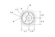
図4に、遠位チップ10の嵌め込み穴11を遠位チップ10の軸心部Pから偏心した位置Qに設けた実施態様を示す。嵌め込み穴11を遠位チップ10の軸心部Pから偏心させて設けることで、前記嵌め込み穴11に嵌め込まれたステム2の前記随腔4内での位置を自由に位置決め調整することができる。
即ち、遠位チップ10が嵌め込まれるステム2の遠位端部近傍においては、そのステム2と大腿骨3の内周面との距離を、仮に内距離L1、外距離L2、右距離L3、左距離L4とすると、それらの各距離L1、L2、L3、L4を自由に変更調整することができる。その変更調整はステム2に遠位チップ10を嵌め込む際に、遠位チップ10の水平方向に360度以下の角度で適当に回転させればよい。
以上のように、偏心した嵌め込み穴11を持つ遠位チップ10を使用することで、ステム2の遠位端部2aの随腔4内での位置を自由に調整して位置決めすることができる。そしてこのことは、個々の人間の骨の湾曲具合に応じて、ステム2を全体としてバランス良く随腔4内に挿入、位置決めする場合に非常に重要となってくる。更に言えば、ステム2の遠位端部2aの随腔4内での位置(随腔4内の水平面上での位置)を好ましい位置に調整して配置できれば、ステム2の近位部の位置調整(視覚できるので比較的容易である)と相俟ってステム2全体を随腔4内でバランスのとれた良好な位置に配置させることができる。
【0019】
上記図4に示す実施形態では、取り付け手段である嵌め込み穴11の位置を遠位チップ10の軸心部Pから偏心して設けているが、嵌め込み穴11の代わりに、取り付け手段として上記遠位チップ10の雄螺子部12や雌螺子部13等の螺合螺子を軸心部Pから偏心して設けるようにすることができる。
また同様に嵌め込み穴11の代わりに、取り付け手段として嵌め込み突起を軸心部Pから偏心して設けるようにすることができる。
【0020】
図5に示す実施形態は、図4に示す実施形態と同様に、遠位チップ10の嵌め込み穴11を遠位チップ10の軸心部Pから偏心した位置Qに設けたものである。が、前記嵌め込み穴11の形状、詳しくは水平断面形状を多角形としている。
このように多角形とした嵌め込み穴11を用いることで、同じ水平断面形状を有するステム2の遠位端部付近に対して、嵌合固定が容易に、確実に行える他、特に遠位チップ10をその多角形の1角の角度を単位として、一角ずつ順次回転させることで、ステム2の回りにおける遠位チップ10の出っ張りの程度の調節を容易に且つ確実に行うことができる。
なお本実施形態では、遠位チップ10の嵌め込み穴11をテーパー状に構成しているが、必ずしもテーパー状でなくてもよく、ストレートな穴であってもよい。
【0021】
図6に示す実施形態では、遠位チップ10の偏心させた嵌め込み穴11を、貫通させることなく設け、且つ嵌め込み穴11の底から嵌め込み突起14を設け、この嵌め込み突起14をステム2の遠位端部2aに形成した嵌め込み穴2bに対して挿嵌することで、遠位チップ10をステム2に取り付けるようにしている。
前記嵌め込み突起14は遠位チップ10の軸心部Pから偏心した位置Qに位置する。この嵌め込み突起14がステム2の嵌め込み穴2aに対して円周方向に回転・調整しながら嵌め込むことで、ステム2の遠位端部2aの位置を随腔4内で調節することができる。
なお前記嵌め込み突起14の場合も多角形の柱としている。多角形とすることによるメリットは既述の通りである。
【0022】
図7に示す実施形態では、遠位チップ10の偏心させた嵌め込み穴11を、貫通させることなく設け、且つ嵌め込み穴11の底に更に嵌め込み小穴15を設け、この嵌め込み小穴15に対してステム2の遠位端部2aに形成した嵌め込み突起2cを挿嵌することで、遠位チップ10をステム2に取り付けるようにしている。
前記嵌め込み小穴15は遠位チップ10の軸心部Pから偏心した位置Qに位置する。この嵌め込み小穴15とステム2の前記嵌め込み突起2cとを円周方向に相互に回転調整しながら嵌め込むことで、ステム2の遠位端部2aの位置を随腔4内で調節することができる。
なお前記嵌め込み小穴15の場合も多角形の穴としている。多角形とすることによるメリットは既述の通りである。
【0023】
図8に示すように、遠位チップ10の嵌め込み穴11には、その内周面から中心方向に向けて突出する縦方向の凸条16を設けることができる。凸条16の代わりに凸部を設けてもよい。
このような凸条16や凸部を遠位チップ10の嵌め込み穴11の内周面から中心方向へ向けて設けることで、嵌め込み穴11の内周面が平坦な遠位チップ10の場合よりも、より確実に強固に遠位チップ10をステム2に取り付けることができる。
【0024】
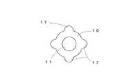
図9に示すように、遠位チップ10の外周は円形である必要はない。遠位チップ10の外周形状を多角形やその他の凹凸形状とすることができる。図9では遠位チップ10の外周に膨出部17を、等間隔で設けている。このように遠位チップ10の外周を凹凸形状にすることで、該凹凸部の隙間を自由に骨随液等が行き来することができる。
【0025】
図10に更に本発明の遠位チップの他の実施形態を示す。本実施形態では遠位チップ10をピン状のものとしている。ピン状の遠位チップ10を複数本用意し、これをステム2の遠位端部2a付近の側周面に円周方向に適当な間隔(この実施形態の場合は60度間隔で設けられた取り付け穴2dに対して差し込んで取り付けるようにしている。ピン状の遠位チップ10がステム2の遠位端部2a付近の側周に複数個、放射状に取り付けられることで、ステム2の遠位端部2aが随腔4内面から離間した状態で安定して位置決めされる。
前記ピン状の遠位チップ10の先端部は丸い曲面とされ、随腔4内面に対して当接した際に軟らかく当接するようにしている。
また前記ピン状の遠位チップ10の基端側を螺子として、ステム2の取り付け穴2dの螺子に対して螺合して差し込んで取り付けるようにしてもよい。
【0026】
更に前記ピン状の遠位チップ10はその用いる複数個を長さの異なるものとし、この長さの異なるピン状の遠位チップ10をステム2の各取り付け穴2dに取り付けることで、各ピン状の遠位チップ10のステム2からの突出長さが円周方向において異なるように構成することができる。このように構成することで、ステム2の遠位端部2aを随腔4内の偏心した位置に安定して位置決めすることができる。その際、ピン状の遠位チップ10の長さを種々選択し、又どの長さのピン状の遠位チップ10をステム2の円周方向のどの位置に取り付けるかを種々選択することで、ステム2の遠位端部2aの髄空4内での偏心位置を自在に調節することができる。
【0027】
本発明の遠位チップ10は、人工股関節の他、人工肩関節、人工肘関節、人工手関節、人工指関節、人工膝関節、人工足関節にも適用することができる。
【0028】
【発明の効果】
本発明は以上の構成、作用よりなり、請求項1に記載の人工関節のステム位置決め用遠位チップによれば、セメントレスの人工関節のステム遠位端部付近に取り付けられ、これによって前記人工関節のステムが髄腔内へ挿入される際にステム遠位端部が骨の髄腔内面に直接には当接しないようにガイドすると共に、ステム挿入完了時におけるステム遠位端部の髄腔内での位置を安定的に位置決めするための人工関節のステム位置決め用遠位チップであって、遠位チップはピン状のものとし、人工関節のステム遠位端部付近の側周面に円周方向に適当な間隔で複数個設けられた取り付け穴に対して差し込んで取り付けるように構成してあるので、
セメントレスの人工関節のステムが髄腔内へ挿入される際にステム遠位端部が直接的に骨の髄腔内面に当らないようにしながらガイドすると共に、前記セメントレスの人工関節のステム遠位端部を随腔内に安定して位置決めすることを可能となる。
特に、ピン状の遠位チップを用いてステムの遠位端部を随腔内に簡単に且つ安定して位置決めすることができる。しかも遠位チップはピン状であるので、これをステムの取り付け穴に対して差し込むことで、簡単に準備完了することができる。
また請求項2に記載の人工関節のステム位置決め用遠位チップによれば、上記請求項1に記載の構成による効果に加えて、遠位チップは長さの異なるものを用意し、ステムの遠位端部付近の側周面に円周方向に適当な間隔で複数個取り付けられた際に、遠位チップの突出長さが円周方向において異なるように構成することにより、
種々の長さのピン状の遠位チップを組み合せることにより、非常に簡単にステムの遠位端部を髄腔内の所定の偏心位置に、自在に且つ確実に位置決め配置することができる。
また請求項3に記載の人工関節のステム位置決め用遠位チップによれば、上記請求項1又は2に記載の構成による効果に加えて、遠位チップを生体内分解吸収性材料で構成してあることにより、
ステムの近位部と海面骨とが強固に結合する手術の数ヶ月後には、遠位チップが分解・吸収されてしまうようにすることが可能となり、遠位チップと骨とが長期にわたって当接することに起因する、セメントレスの人工関節での骨溶解及び人工関節のゆるみ、痛みや骨折を解消することができる。
【図面の簡単な説明】
【図1】 本発明の遠位チップを取り付けた人工関節のステムが大腿骨の髄腔内に挿入された状態を示す断面図である。
【図2】 (A)〜(F)はそれぞれ嵌め込み穴を用いた遠位チップの実施形態を示す斜視図である。
【図3】 (A)、(B)はそれぞれ螺合式の遠位チップの実施形態を示す斜視図である。
【図4】 遠位チップの嵌め込み穴を軸心部から偏心させた実施形態を示す平面図である。
【図5】 (A)、(B)は遠位チップの嵌め込み穴を軸心部から偏心させた他の実施形態を示す遠位チップの平面図と縦断面図である。
【図6】 (A)、(B)は遠位チップの嵌め込み穴を軸心部から偏心させた更に他の実施形態を示す遠位チップの平面図と縦断面図である。
【図7】 (A)、(B)は遠位チップの嵌め込み穴を軸心部から偏心させた更に他の実施形態を示す遠位チップの平面図と縦断面図である。
【図8】 遠位チップの嵌め込み穴の内周面に軸心方向に突出する凸条を形成した実施形態を示す平面図である。
【図9】 遠位チップの外周に凹凸形状を構成した実施形態を示す平面図である。
【図10】 (A)、(B)は遠位チップの更に他の実施形態を示す正面図と水平断面図である。
【符号の説明】
1 骨頭球
2 ステム
2a 遠位端部
2b 嵌め込み穴
2c 嵌め込み突起
2d 取り付け穴
4 随腔
5 ポーラス加工表面
10 遠位チップ
11 嵌め込み穴
12 雄螺子部
13 雌螺子部
14 嵌め込み突起
15 嵌め込み小穴
16 凸条
17 膨出部
P 軸心部
Q 偏心した位置
L1 内距離
L2 外距離
L3 右距離
L4 左距離[0001]
BACKGROUND OF THE INVENTION
The present invention relates to a distal tip for stem positioning of an artificial joint. More particularly, the present invention relates to a distal tip for positioning a stem used in a cementless type artificial joint.
[0002]
[Prior art]
The prosthesis is roughly divided into cement-type prosthesis that is filled with cement in the medullary cavity and the gap between the stem and bone of the inserted prosthesis is filled with cement, and without using cement. It can be divided into cementless artificial joints that directly join the stem and bone of the artificial joint.
In the case of a cementless type artificial joint, a stable bond between the artificial joint and the bone can be obtained by bonding with the cancellous bone at the proximal portion of the stem. However, the cancellous bone takes several months at the earliest.
In a cementless type artificial joint, for example, when targeting a hip joint, in order to increase the occupancy rate of the artificial joint in the bone marrow cavity of the femoral stem, the femoral stem is not only the proximal part but also the distal part. The stem that became thicker was used. However, since the bone marrow cavity is physiologically curved, the stem tip of the prosthetic joint hits the bone from inside the medullary canal, causing stress concentration in that part, resulting inosteolysis (osteolysis ), It was a cause of looseness or pain or fracture.
In order to solve the above-mentioned problems, a device in which the distal side of the stem of the artificial joint is tapered is provided. However, when the distal end of the stem is thin, the distal end of the stem is thin, so when the stem is installed in the medullary cavity, the distal end of the stem is inserted into the center of the medullary canal. Difficult, prone to valgus and valgus, and this causes the problem that the entire stem is prone to anteversion and posterior position in the medullary cavity, resulting inosteolysis as a result. There was a problem of loosening.
In order to further solve this problem, in a cementless type artificial joint, a metallic distal tip called a centralizer is used, and this is attached near the distal end of the stem so that the distal end of the stem is fixed. A method was provided for positioning in the center of the medullary canal. However, with this method, the distal tip attached to the stem now hits the bone, causing stress concentration at that portion, resulting inosteolysis and loosening of the artificial joint.
Due to the above circumstances, in the present situation, in a cementless type artificial joint, a device is necessary for insertion, but a surgical operation is performed mainly using a tapered stem without a distal tip.
[0003]
On the other hand, a cement-type artificial joint is a type in which cement is filled in the medullary cavity and the inserted stem and bone are fixed.
This cement-type artificial joint is also provided with a centralizer made of the same kind of plastic or filled cement as a distal tip and attached near the distal end of the stem. The role of the distal tip in this cement-type prosthesis is primarily to position the distal end of the stem at the center of the medullary cavity, thereby homogenizing the filling cement. In a cement-type artificial joint, the inserted stem and cement form a lump.
In addition, Japanese Patent Laid-Open No. 10-309297 discloses a method of using a biodegradable / absorbable plug for a cement-type artificial joint, pre-installing the plug in the medullary cavity, and then filling the cement into the medullary cavity. An invention is disclosed in which the cement is blocked so as not to fill the medullary cavity more deeply than necessary. However, this biodegradable / absorbable plug is a dedicated accessory for cement-type artificial joints, and is intended to prevent the fall of cement.
[0004]
[Problems to be solved by the invention]
As described above, in a cementless type artificial joint, it is easy to position the distal end of the stem at the center of the medullary cavity by attaching the distal tip to the stem of the artificial joint. As a result of stress concentration caused by striking the bone over a long period of time, there has been a problem thatosteolysis occurs and the artificial joint loosens.
On the other hand, since cement-type prosthetic joints are integrated with the cement filled with the stem, problems such as stress concentration, associatedosteolysis , and distortion of the prosthetic joints due to the use of the distal tip are not serious problems. It was.
[0005]
Therefore, the present invention eliminates the drawbacks and problems of the conventional cementless artificial joint, can guide the insertion of the stem in the cementless artificial joint into the medullary cavity, and is inserted into the medullary cavity. The position of the distal end of the stem can be positioned at a planned position, so that the position of the entire stem in the medullary cavity can be held in a predetermined position, and the distal tip can be used. It is an object of the present invention to provide a distal tip for positioning a stem of an artificial joint that does not causeosteolysis and loosening of the artificial joint, which have conventionally occurred.
[0006]
[Means for Solving the Problems]
To achieve the above object, the distal tip for positioning the stem of the artificial joint of the present invention is attached near the distal end of the stem of the cementless artificial joint, whereby the stem of the artificial joint is inserted into the medullary canal. Guides the distal end of the stem so that it does not directly contact the inner surface of the bone cavity of the bone, and stably positions the distal end of the stem in the medullary cavity when the stem is inserted A distal tip for positioning the stem of the artificial joint, and thedistal tip is pin-shaped, and a plurality of tips are provided on the side peripheral surface near the distal end of the stem of the artificial joint at appropriate intervals in the circumferential direction. The first feature is thatthe mounting hole is configured tobe inserted into the mounting hole .
[0007]
In addition to the first feature described above, the distal tip for positioning the stem of the artificial joint according to the present inventionis provided with a distal tip having a different length. A circular tip is provided on the side surface near the distal end of the stem. The second feature is that when a plurality of peripheral tips are attached at appropriate intervals in the circumferential direction, the protruding length of the distal tip is different in the circumferential direction.
[0008]
In addition tothe first or second feature,the distal tip for stem positioning of an artificial joint of the present invention has athird feature that thedistal tip is made of a biodegradable and absorbable material ..
[0009]
Upper Symbol first prosthesis according to the features of the stem positioning the distal tip, that mounted in the vicinity of the stem distal end portion of the cementless artificial joint, when the prosthesis stem is inserted into the intrathecal It is possible to guide the distal end of the stem while preventing it from directly contacting the inner surface of the medullary cavity of the bone.
And the position in the medullary cavity of a stem distal end part at the time of completion of stem insertioncan be positioned stably.
[0010]
In particular, since the distal tip has a pin shape and is inserted into the mounting hole of the stem of the artificial joint, it can be easily attached. In addition, the distal tip of the stem is attached by inserting a pin-shaped distal tip into each of a plurality of mounting holes provided at appropriate intervals in the circumferential direction on the side surface near the distal end of the stem. It is possible to easily and stably position at a predetermined position in a state where the vicinity of the portion is separated from the inner surface of the continuous cavity.
[0011]
The distal tip for positioning the stem of the prosthesis according to the second featureis provided with a pin-like distal tip having a different length in addition to the function and effect of the first feature. Pins with different lengths are constructed by attaching the distal tip from the stem in the circumferential direction so that the protruding length of the distal tip is different in the circumferential direction. The distal tip of the stem can be easily and stably positioned at a predetermined eccentric position in the medullary canal.
[0012]
Further, the distal tip for positioning the stem of the artificial joint according to the third feature has the distal tip madeof a biodegradable and absorbable material in addition to the function and effect of the firstor second feature.After several months of surgery when the proximal part of the stem and the sea surface bone are tightly coupled, it is possible to allow the distal tip to be disassembled and absorbed, and the distal tip and the bone will be in contact with each other over a long period of time. It is possible to eliminate osteolysis in a cementless artificial joint, loosening of the artificial joint, pain and fracture caused by contact.
[0013]
DETAILED DESCRIPTION OF THE INVENTION
FIG. 1 is a cross-sectional view showing a state where a stem of anartificial joint to which a distal tip of the present invention is attached is inserted into a medullary cavity of a femur, and FIGS. 2A to 2F each use a fitting hole. 3 is a perspective view showing various embodiments of the distal tip, FIGS. 3A and 3B are perspective views showing embodiments of a screw-type distal tip, and FIG. 4 is an axis of a fitting hole of the distal tip. FIG. 5 (A) and FIG. 5 (B) are distal views showing other embodiments in which the fitting hole of the distal tip is eccentric from the axial center. A plan view of the tip and a longitudinal sectional view of the distal tip. FIGS. 6A and 6B are plan views of the distal tip showing still another embodiment in which the fitting hole of the distal tip is eccentric from the axial center. Fig. 7 is a longitudinal sectional view of the distal tip, and Figs. 7A and 7B are views in which the fitting hole of the distal tip is offset from the axial center. FIG. 8 is a plan view of a distal tip and a longitudinal sectional view of the distal tip showing another embodiment, and FIG. 8 shows an embodiment in which a protruding ridge projecting in the axial direction is formed on the inner peripheral surface of the fitting hole of the distal tip. FIG. 9 is a plan view showing an embodiment in which an uneven shape is formed on the outer periphery of the distal tip, and FIGS. 10A and 10B are a front view and a horizontal view showing still another embodiment of the distal tip. It is sectional drawing.
[0014]
First, referring to FIG. 1,
A
The
When the
The horizontal cross-sectional diameter of the
In addition, the
[0015]
The
On the other hand, the
The biodegradable absorbable material is hydrolyzed and absorbed in the
[0016]
Referring to FIG. 2, the shape of the
Further, the shape of the
Moreover, the shape of the
The shape of the
The shape of the
[0017]
Referring to FIG. 3, the
[0018]
In the case of the
FIG. 4 shows an embodiment in which the
That is, in the vicinity of the distal end portion of the
As described above, by using the
[0019]
In the embodiment shown in FIG. 4, the position of the
Similarly, instead of the
[0020]
In the embodiment shown in FIG. 5, as in the embodiment shown in FIG. 4, the
By using the polygonal
In addition, in this embodiment, although the
[0021]
In the embodiment shown in FIG. 6, the eccentric
The
The
[0022]
In the embodiment shown in FIG. 7, the eccentric
The fitting
The fitting
[0023]
As shown in FIG. 8, the
By providing
[0024]
As shown in FIG. 9, the outer periphery of the
[0025]
FIG. 10 further shows another embodiment of the distal tip of the present invention. In this embodiment, the
The tip of the pin-shaped
Alternatively, the proximal end side of the pin-shaped
[0026]
Further, a plurality of the pin-shaped
[0027]
The
[0028]
【The invention's effect】
The present invention has the above-described configuration and action. According to the distal tip for positioning a stem of an artificial joint according to
When the stem of the cementless artificial joint is inserted into the medullary canal, the distal end of the stem is guided not to directly contact the inner surface of the medullary cavity of the bone, It is possible to stably position the distal end in the space.
In particular, the distal end of the stem can be easily and stably positioned in the extracavity using a pin-shaped distal tip. Moreover, since the distal tip is pin-shaped, it can be easily prepared by inserting it into the mounting hole of the stem.
According to the distal tip for positioning of artificial joint stem according to
By combining various lengths of pin-shaped distal tips, the distal end of the stem can be freely and reliably positioned at a predetermined eccentric position in the medullary canal.
According to the distal tip for positioning a stem of an artificial joint according to
After several months of surgery, where the proximal portion of the stem and the sea surface bone are tightly coupled, it is possible to allow the distal tip to be disassembled and absorbed, and the distal tip and the bone abut for a long time It is possible to eliminate osteolysis in a cementless artificial joint, loosening of the artificial joint, pain and fracture caused by the above.
[Brief description of the drawings]
FIG. 1 is a cross-sectional view showing a state where a stem of anartificial joint to which a distal tip of the present invention is attached is inserted into a medullary cavity of a femur.
FIGS. 2A to 2F are perspective views showing an embodiment of a distal tip using a fitting hole, respectively.
3A and 3B are perspective views showing an embodiment of a screw-type distal tip, respectively.
FIG. 4 is a plan view showing an embodiment in which a fitting hole of a distal tip is eccentric from an axial center portion.
FIGS. 5A and 5B are a plan view and a longitudinal sectional view of a distal tip showing another embodiment in which the fitting hole of the distal tip is eccentric from the axial center portion.
FIGS. 6A and 6B are a plan view and a longitudinal sectional view of a distal tip showing still another embodiment in which the fitting hole of the distal tip is eccentric from the axial center portion.
FIGS. 7A and 7B are a plan view and a longitudinal sectional view of a distal tip showing still another embodiment in which the fitting hole of the distal tip is eccentric from the axial center portion.
FIG. 8 is a plan view showing an embodiment in which ridges projecting in the axial direction are formed on the inner peripheral surface of the fitting hole of the distal tip.
FIG. 9 is a plan view showing an embodiment in which an uneven shape is configured on the outer periphery of the distal tip.
10A and 10B are a front view and a horizontal sectional view showing still another embodiment of the distal tip.
[Explanation of symbols]
DESCRIPTION OF
Claims (3)
Translated fromJapanesePriority Applications (3)
| Application Number | Priority Date | Filing Date | Title |
|---|---|---|---|
| JP2002333193AJP3779674B2 (en) | 2002-11-18 | 2002-11-18 | Distal tip for stem positioning of artificial joints |
| EP03026084AEP1419749A1 (en) | 2002-11-18 | 2003-11-12 | Distal tip for the positioning of artificial joint stem |
| US10/713,266US20040107002A1 (en) | 2002-11-18 | 2003-11-17 | Distal tip for the positioning of artificial joint stem |
Applications Claiming Priority (1)
| Application Number | Priority Date | Filing Date | Title |
|---|---|---|---|
| JP2002333193AJP3779674B2 (en) | 2002-11-18 | 2002-11-18 | Distal tip for stem positioning of artificial joints |
Related Child Applications (1)
| Application Number | Title | Priority Date | Filing Date |
|---|---|---|---|
| JP2006011850ADivisionJP2006110383A (en) | 2006-01-20 | 2006-01-20 | Distal chip for positioning stem of artificial joint |
Publications (2)
| Publication Number | Publication Date |
|---|---|
| JP2004166767A JP2004166767A (en) | 2004-06-17 |
| JP3779674B2true JP3779674B2 (en) | 2006-05-31 |
Family
ID=32171432
Family Applications (1)
| Application Number | Title | Priority Date | Filing Date |
|---|---|---|---|
| JP2002333193AExpired - Fee RelatedJP3779674B2 (en) | 2002-11-18 | 2002-11-18 | Distal tip for stem positioning of artificial joints |
Country Status (3)
| Country | Link |
|---|---|
| US (1) | US20040107002A1 (en) |
| EP (1) | EP1419749A1 (en) |
| JP (1) | JP3779674B2 (en) |
Families Citing this family (17)
| Publication number | Priority date | Publication date | Assignee | Title |
|---|---|---|---|---|
| US20040024471A1 (en)* | 2002-06-27 | 2004-02-05 | Ferree Bret A. | Bone cell covered arthroplasty devices |
| JP4095003B2 (en)* | 2003-09-12 | 2008-06-04 | 泉工医科工業株式会社 | Mid- and distal-tips for artificial joints |
| US7763080B2 (en)* | 2004-04-30 | 2010-07-27 | Depuy Products, Inc. | Implant system with migration measurement capacity |
| US20060173424A1 (en)* | 2005-02-01 | 2006-08-03 | Conlon Sean P | Surgically implantable injection port having an absorbable fastener |
| US8007538B2 (en) | 2005-02-25 | 2011-08-30 | Shoulder Innovations, Llc | Shoulder implant for glenoid replacement |
| US8778028B2 (en) | 2005-02-25 | 2014-07-15 | Shoulder Innovations, Inc. | Methods and devices for less invasive glenoid replacement |
| US20230080207A1 (en) | 2005-02-25 | 2023-03-16 | Shoulder Innovations, Inc. | Methods and devices for less invasive glenoid replacement |
| NL1032851C2 (en)* | 2006-11-10 | 2008-05-14 | Fondel Finance B V | Kit and method for fixing a prosthesis or part thereof and / or filling bony defects. |
| US8066770B2 (en)* | 2007-05-31 | 2011-11-29 | Depuy Products, Inc. | Sintered coatings for implantable prostheses |
| US8632603B2 (en)* | 2010-09-21 | 2014-01-21 | Tornier, Inc. | Implant positioning systems for orienting prosthesis |
| US9381086B2 (en) | 2010-11-30 | 2016-07-05 | Shoulder Innovations, Llc | Stem for use in joint arthroplasty |
| US10492926B1 (en) | 2014-09-04 | 2019-12-03 | Shoulder Innovations, Inc. | Alignment guide for humeral or femoral stem replacement prostheses |
| EP4520302A3 (en) | 2017-04-14 | 2025-04-16 | Shoulder Innovations, Inc. | Total shoulder prosthesis having inset glenoid implant convertible from anatomic to reverse |
| US12138172B2 (en) | 2018-04-30 | 2024-11-12 | Shoulder Innovations, Inc. | Inset/onlay glenoid, porous coated convertible glenoid, and humeral heads with textured undersides |
| AU2020237088B2 (en) | 2019-03-11 | 2025-09-04 | Shoulder Innovations, Inc. | Total reverse shoulder systems and methods |
| USD977643S1 (en) | 2019-03-12 | 2023-02-07 | Shoulder Innovations, Inc. | Humeral stem implant |
| CN112386373B (en)* | 2020-11-26 | 2024-08-30 | 北京爱康宜诚医疗器材有限公司 | Intramedullary fusion device and femoral prosthesis component with same |
Family Cites Families (8)
| Publication number | Priority date | Publication date | Assignee | Title |
|---|---|---|---|---|
| FR2651118A1 (en)* | 1989-08-30 | 1991-03-01 | Aubaniac Jean | Cementless hip prosthesis |
| US5201771A (en)* | 1989-09-15 | 1993-04-13 | Belykh Sergei I | Endoprosthesis of the hip joint |
| DE4220216C1 (en)* | 1992-06-20 | 1994-01-13 | S & G Implants Gmbh | Endoprosthesis - has bio-resorbable distance rings to set gap between prosthesis and bone |
| FR2698783B1 (en)* | 1992-12-03 | 1995-02-03 | Jurg Aebi | Centering device for total hip prosthesis. |
| FR2725617B1 (en)* | 1994-10-12 | 1997-09-19 | Prost Didier | FEMALE ROD FOR HIP PROSTHESIS |
| GB9806156D0 (en)* | 1998-03-24 | 1998-05-20 | Depuy Int Ltd | An end cap spacer for a joint prosthesis |
| EP0968690A1 (en)* | 1998-07-02 | 2000-01-05 | Sulzer Orthopädie AG | Plug system for the medullary canal of a tubular bone |
| US6139584A (en)* | 1998-12-22 | 2000-10-31 | Depuy Orthopaedics, Inc. | Proximal femoral sleeve for a revision hip prosthesis |
- 2002
- 2002-11-18JPJP2002333193Apatent/JP3779674B2/ennot_activeExpired - Fee Related
- 2003
- 2003-11-12EPEP03026084Apatent/EP1419749A1/ennot_activeWithdrawn
- 2003-11-17USUS10/713,266patent/US20040107002A1/ennot_activeAbandoned
Also Published As
| Publication number | Publication date |
|---|---|
| JP2004166767A (en) | 2004-06-17 |
| EP1419749A1 (en) | 2004-05-19 |
| US20040107002A1 (en) | 2004-06-03 |
Similar Documents
| Publication | Publication Date | Title |
|---|---|---|
| JP3779674B2 (en) | Distal tip for stem positioning of artificial joints | |
| US7776098B2 (en) | Modular femoral prosthesis with on-axis junction | |
| JP4838731B2 (en) | Femoral hip prosthesis and transplantation method | |
| JP3657240B2 (en) | Oval acetabular cup | |
| US6464728B1 (en) | Modular neck for femur replacement surgery | |
| CA2079256C (en) | Hip prosthesis | |
| EP2400928B1 (en) | Elbow prosthesis | |
| KR101340861B1 (en) | Humeral component of a shoulder joint prosthesis | |
| US5507819A (en) | Apparatus and method for stabilizing a humeral head in a shoulder | |
| US5725595A (en) | Cannulated cementless hip stem prosthesis | |
| US9561110B2 (en) | Elbow prosthesis | |
| EP3042637A1 (en) | Reverse shoulder prosthesis | |
| US20110060417A1 (en) | Shoulder joint prosthesis, especially reverse shoulder joint prosthesis | |
| US7572297B2 (en) | Tapered joint prosthesis | |
| EP2108338A2 (en) | Resurfacing femoral head component | |
| JP2004121850A (en) | Inverted type humerus prosthesis | |
| NZ554377A (en) | Intramedullary pin for insertion into the medullary space of a femur | |
| JP4387146B2 (en) | Adjustable orthopedic instrument | |
| JP2008529613A (en) | Hip prosthesis system | |
| CN114423385A (en) | Modular prosthesis for at least partial replacement of long bones adjacent to a joint | |
| WO2015150347A1 (en) | Endoprosthesis | |
| CN117257529B (en) | Tantalum coating hip joint prosthesis system | |
| JP4095003B2 (en) | Mid- and distal-tips for artificial joints | |
| GB2539219A (en) | Femoral stem prosthesis | |
| JP2006110383A (en) | Distal chip for positioning stem of artificial joint |
Legal Events
| Date | Code | Title | Description |
|---|---|---|---|
| A711 | Notification of change in applicant | Free format text:JAPANESE INTERMEDIATE CODE: A711 Effective date:20050309 | |
| A521 | Written amendment | Free format text:JAPANESE INTERMEDIATE CODE: A821 Effective date:20050309 | |
| A131 | Notification of reasons for refusal | Free format text:JAPANESE INTERMEDIATE CODE: A131 Effective date:20051122 | |
| A521 | Written amendment | Free format text:JAPANESE INTERMEDIATE CODE: A523 Effective date:20060120 | |
| TRDD | Decision of grant or rejection written | ||
| A01 | Written decision to grant a patent or to grant a registration (utility model) | Free format text:JAPANESE INTERMEDIATE CODE: A01 Effective date:20060221 | |
| A61 | First payment of annual fees (during grant procedure) | Free format text:JAPANESE INTERMEDIATE CODE: A61 Effective date:20060302 | |
| R150 | Certificate of patent or registration of utility model | Free format text:JAPANESE INTERMEDIATE CODE: R150 | |
| FPAY | Renewal fee payment (event date is renewal date of database) | Free format text:PAYMENT UNTIL: 20100310 Year of fee payment:4 | |
| FPAY | Renewal fee payment (event date is renewal date of database) | Free format text:PAYMENT UNTIL: 20110310 Year of fee payment:5 | |
| FPAY | Renewal fee payment (event date is renewal date of database) | Free format text:PAYMENT UNTIL: 20120310 Year of fee payment:6 | |
| FPAY | Renewal fee payment (event date is renewal date of database) | Free format text:PAYMENT UNTIL: 20130310 Year of fee payment:7 | |
| FPAY | Renewal fee payment (event date is renewal date of database) | Free format text:PAYMENT UNTIL: 20130310 Year of fee payment:7 | |
| FPAY | Renewal fee payment (event date is renewal date of database) | Free format text:PAYMENT UNTIL: 20140310 Year of fee payment:8 | |
| LAPS | Cancellation because of no payment of annual fees |