JP3779607B2 - Thermal transfer printer - Google Patents
Thermal transfer printerDownload PDFInfo
- Publication number
- JP3779607B2 JP3779607B2JP2001385697AJP2001385697AJP3779607B2JP 3779607 B2JP3779607 B2JP 3779607B2JP 2001385697 AJP2001385697 AJP 2001385697AJP 2001385697 AJP2001385697 AJP 2001385697AJP 3779607 B2JP3779607 B2JP 3779607B2
- Authority
- JP
- Japan
- Prior art keywords
- ribbon
- paper
- ink
- thermal head
- ink ribbon
- Prior art date
- Legal status (The legal status is an assumption and is not a legal conclusion. Google has not performed a legal analysis and makes no representation as to the accuracy of the status listed.)
- Expired - Fee Related
Links
- 239000000976inkSubstances0.000claimsdescription69
- 230000007246mechanismEffects0.000claimsdescription10
- 238000010438heat treatmentMethods0.000claimsdescription9
- 230000007723transport mechanismEffects0.000claimsdescription8
- 239000003086colorantSubstances0.000claimsdescription6
- 238000011144upstream manufacturingMethods0.000claimsdescription2
- 238000004804windingMethods0.000description34
- 230000002093peripheral effectEffects0.000description6
- 238000003780insertionMethods0.000description5
- 230000037431insertionEffects0.000description5
- 229910052751metalInorganic materials0.000description3
- 239000002184metalSubstances0.000description3
- 238000007639printingMethods0.000description3
- 238000000034methodMethods0.000description2
- 239000000853adhesiveSubstances0.000description1
- 230000001070adhesive effectEffects0.000description1
- 229910052782aluminiumInorganic materials0.000description1
- XAGFODPZIPBFFR-UHFFFAOYSA-NaluminiumChemical compound[Al]XAGFODPZIPBFFR-UHFFFAOYSA-N0.000description1
- 238000004512die castingMethods0.000description1
- 230000000694effectsEffects0.000description1
- 230000007613environmental effectEffects0.000description1
- 230000017525heat dissipationEffects0.000description1
- 239000003550markerSubstances0.000description1
- 239000000463materialSubstances0.000description1
- 239000011347resinSubstances0.000description1
- 229920005989resinPolymers0.000description1
- 238000010023transfer printingMethods0.000description1
Images


Landscapes
- Electronic Switches (AREA)
- Impression-Transfer Materials And Handling Thereof (AREA)
Description
Translated fromJapanese【0001】
【発明の属する技術分野】
本発明は熱転写プリンタに係わり、特に、インクリボンの巻取り低トルクで確実に行うことが可能な熱転写プリンタに関する。
【0002】
【従来の技術】
従来から、記録用紙への行ごと、またはページごとの記録を迅速に行う記録装置として、記録用紙の幅方向に沿って発熱素子が整列は位置されたサーマルヘッドでインクリボンのインクを熱転写印刷する熱転写プリンタがある。
このような熱転写プリンタは、静寂性、操作性、低コスト性等の理由により大量出力が可能な業務用だけでなく、小型で安価な家庭用、さらにはバッテリー駆動が可能な携帯用へとその用途が拡大している。
【0003】
従来の熱転写プリンタは、フレームのほぼ中央部に、回転自在に支持された略円柱状のプラテンローラが配設されている。このプラテンローラと対向する位置には、プラテンローラの長手方向に沿って複数の発熱素子が整列形成されたサーマルヘッドが、フレームの一方の側板に、片持ち支持により取り付けられている。
また、プラテンローラは、プラテンローラをサーマルヘッドに対して接離させるプラテンレバーの先端部に取り付けられており、このプラテンレバーは、その基端部がフレームの一方と他方の両側板に両持ち支持されている。
【0004】
また、プラテンローラの手前側には、プラテンローラとサーマルヘッドとの簡易記録用紙を搬送するための搬送ローラが回転可能に配設されている。前記搬送ローラの外周部には、搬送ローラと共に記録用紙を狭持しつつ搬送するための圧接ローラが圧接されている。
また、フレームの一方の側板には、巻取りコアおよび供給コアにインクリボンを巻回して収納してなるリボンカセットを、フレーム内に横から挿入するための切り欠き部が形成されている。
【0005】
前記インクリボンは、異なる複数の色、例えばイエロー、マゼンタ、シアン等のインクを順番に塗布したカラーリボンからなっている。
なお、リボンカセットを切り欠き部に挿入してフレームに装着した装着状態において、インクリボンがプラテンローラとサーマルヘッドとの間に位置して、供給コアから巻取りコアに巻取り可能となっている。
【0006】
また、リボンカセットをフレームに装着状態におけるリボンカセットは、巻取りコアが一方の側板に配設した巻取りボビンに係合し、巻取りボビンの回転駆動力で、インクリボンを巻取りコアに巻取り可能になっている。
そして、巻取りボビンを回転駆動させて、巻取りコアにインクリボンを巻取るときに、巻取りコアの回転トルクが所定値を越えると、巻取りボビンがスリップ回転して、インクリボンが延びたり、切断したりすることを防止するようになっていた。
【0007】
前記カラーリボンからなるインクリボンを用いてカラー画像を印刷する時は、記録用紙を往復搬送して頭出しを行うと共に、インクリボンの各色毎にリボンセンシングを行い、記録用紙にそれぞれの色のインクを重ね印刷して、所望のカラー画像を印刷していた。
前記リボンセンシングを行う時のインクリボンの巻取り方法は、プラテンローラをサーマルヘッドから離間させた状態で、巻取りボビンを回転させて印刷後のインクを巻取りコアに巻取っていた。
このような従来のインクリボンの巻取り方法は、巻取りコアに巻取るインクリボンの巻取り径の変化、あるいは環境変化等により、巻取りコアの巻取りトルクが変化するために、巻取りボビンのスリップ力を大きくして、巻取りコアの回転トルクが変化しても、スリップしないようにしていた。
【0008】
【発明が解決しようとする課題】
しかし、巻取りボビンのスリップ力を大きくするには、駆動源であるモータの駆動トルクを大きくしなければならなかった。そのために、消費電力のアップ、あるいはモータがコストアップになる問題があった。
本発明は前述したような問題点に鑑みてなされたもので、巻取りボビンのスリップ力が小さくても、無理なく確実にインクリボンの巻き取りが可能な熱転写プリンタを提供することを目的とする。
【0009】
【課題を解決するための手段】
前記課題を解決するための第1の手段として本発明の熱転写プリンタは、複数の発熱素子を整列形成したサーマルヘッドと、異なる複数の色のインクを順番に塗布したインクリボンと、このインクリボンの前記インクを前記サーマルヘッドで熱転写印刷可能な記録用紙と、回転可能な紙送りローラと、この紙送りローラに圧接する圧接ローラからなり前記記録用紙を前記紙送りローラと前記圧接ローラとの間に圧接挟持した状態で前記サーマルヘッドの上流側、および下流側の両方向に搬送可能な用紙搬送機構と、前記記録用紙および前記インクリボンを前記サーマルヘッドとの間に圧接狭持可能なプラテンローラとを有し、
前記インクリボンの所望の色の前記インクが塗布された部分を前記サーマルヘッドの前記発熱素子に対して位置合わせを行うリボンセンシング時は、前記プラテンローラを前記記録用紙と前記インクリボンを介して前記サーマルヘッドに圧接し、前記記録用紙を前記用紙搬送機構で牽引して前記搬送することにより、前記記録用紙との間で生じる摩擦抵抗で、前記インクリボンを前記記録用紙の前記牽引方向と同方向に搬送して巻取りコアに巻取るようにし、このリボンセンシング後にさらに前記プラテンローラを前記サーマルヘッドから離間させ、さらに前記用紙搬送機構により前記記録用紙を前記牽引方向と逆方向に搬送させて前記記録用紙の頭出しを行うようにした構成とした。
【0012】
【発明の実施の形態】
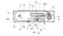
以下、本発明の熱転写プリンタを図1〜図8に基づいて説明する。図1は本発明に係わる熱転写プリンタの側面図であり、図2は図1の下面斜視図であり、図3は図2から底板を取った状態の下面斜視図であり、図4は図1の下面図であり、図5は本発明に係わるプラテンローラ周辺の概略斜視図であり、図6は本発明に係わるプラテンローラの動作を説明する概略図であり、図7は本発明に係わるリボンカセットの側面図であり、図8は本発明に係わる熱転写プリンタの動作を説明する側面図である。
【0013】
本発明の熱転写プリンタは、図1に示すように、内部が空洞の箱状に形成されたフレーム1が配設されている。
このフレーム1は、金属板からなり、手前側に一方の側板部1aと、空洞部を挟んで一方の側板部1aと対向する後方側に他方の側板部1bとが形成され、空洞内部の上部を覆う天板1cと、下部の図示左側の一部を覆う底板1dとにより構成されている。
このようなフレーム1の空洞内部には、カセット装着部2が形成されており、このカセット装着部2は、一方の側板部1aに、図1に示すような開口部2aが形成され、この開口部2aから内部のカセット装着部2に、後述するリボンカセット17を装着可能になっている。
【0014】
また、図2に示すように、フレーム1の一方の側板部1aの外面に沿ってスライド可能な、イジェクト機構3の一部であるスライド板3aが配設されている。(図1ではイジェクト機構3を省略)
また、図3に示すカッセト装着部2の内部の他方の側板部1b近傍には、イジェクト機構3の一部であるバネ部材3bが配設されている。
前記カセット装着部2が形成された部分の他方の側板部1bには、回転可能な巻取りボビン4が配設され、この巻取りボビン4に、後述するリボンカセット17の巻き取りコア20が係合可能になっている。
前記巻取りボビン4は、所定以上の回転トルクが伝達されると、スリップ回転可能になっている。
【0015】
また、フレーム1の両側板部1a、1bには、回転自在の軸部材5が軸支され、この軸部材5の両側板部1a、1bの内側近傍には、それぞれ金属板からなる一対の支持部材6が軸部材5に回転自在に配設されている。
前記軸部材5は、図5に示すように、一対の支持部材6の内側近傍5に、同一方向(図示右方向)に突出する一対の第1と第2のピン5a、5bが、それぞれ圧入等により固着されている。
また、一対の支持部材6は、図5に示す右方向に延出させて互いに対向する方向に略直角のL字状に折り曲げた折り曲げ部6a、6aが、軸部材5の第2ピン5b、5bに当接するようになっている。
また、第1と第2のピン5a、5bに挟まれた部分の軸部材5には、ネジリコイルバネからなる第1のバネ5cが巻回されて配設されており、第1のバネ5cの一端部が支持部材6の折り曲げ部6aに当接し、第1のバネ5cの他端部が第2ピン5bに当接した状態で組み立てられている。
【0016】
このような軸部材5と支持部材6とは、図5に示すように、第1のバネ5cの一端部が当接する支持部材6は、反時計回り方向に付勢され、第1のバネ5cの他端部が第2ピンに当接する軸部材5は、時計回り方向に回転付勢されている。そして、支持部材6の折り曲げ部6aが第1ピン5aに弾接した状態で、軸部材5と支持部材6とが組み立てられている。
また、支持部材6の折り曲げ部6aと反対側の位置で、一対の支持部材6に挟まれた部分には、回転自在のプラテンローラ7が配設されている。このプラテンローラ7は、回転軸7aの外周部にゴムローラ7bが被覆されて構成されている。
このようなプラテンローラ7は、第1のバネ5cの作用で、支持部材6を介して軸部材5と一体的に組み立てられて、軸部材5の正回転、またが逆回転により、プラテンローラ7が矢印C、またはD方向に回動可能になっている。
【0017】
また、図4に示す軸部材5は、フレーム1の図示下方側の他方の側板部1bから外側に突出する部分に、カムレバー8が固着されている。
このカムレバー8は、図5、6に示すように、外周部の一部を図示下方側に突出させてレバー部8aが形成されている。
また、他方の側板部1bから外側に突出する部分で、カムレバ8と他方の側板部1bとの間には、ネジリコイルバネからなる第2のバネ9が巻回されている。この第2のバネ9は、一端部がカムレバー8に、他端部が他方の側板部1bに係止されて、図6に示す軸部材5を常に反時計周り方向に回転付勢している。
そのために、プラテンローラ7は、常に矢印D方向に回動するように弾性付勢されている。
【0018】
また、図6に示すように、カムレバー8のレバー部8aと対向する右側には、カム部材10が配設され、カムレバー8とカム部材10とでカム機構が構成されている。
前記カム部材10は、図6に示すように、右側の一方側が大きな半径で、左側の他方側が小さな半径で形成されて、形状が扇状になっている。
そして、小さな半径の外周部をレバー部材8aに当接させた状態から、カム部材10を回転させて、大きな半径の外周部がレバー部8aを押圧することにより、第2のバネ部材9の付勢力に抗してカムレバー8が回転する。このカムレバー8の回転で軸部材5も回転し、プラテンローラ7が矢印C方向に回動するようになっている。
更にカム部材10を回転させると、小さな半径の外周部がレバー部8aに当接して、第2のバネ9のバネ力で、軸部材5が逆転してプラテンローラ7が矢印D方向に回動するようになっている。
【0019】
また、プラテンローラ7と対向する位置にサーマルヘッド11が配設され、このサーマルヘッド11は、接着剤等でヘッド取付台12に固着されている。このヘッド取付台12は、アルミダイカスト等の放熱性の良い材料からなり、フレーム1の他方の側板部1bにネジ止め等により片持ち支持されて取り付けられている。
前記他方の側板部1bに片持ち支持されたヘッド取付台12は、自由端12a側がカセット装着部2の開口部2aから若干外側に突出した状態になっている。また、フレーム1の天板1cとヘッド取付台12との間のカセット装着部2には、所定寸法の隙間部2cが形成されている。
【0020】
また、図1に示すプラテンローラ7の図示右側には、用紙搬送機構である紙送りローラ13と、この紙送りローラ13に圧接する圧接ローラ14とが配設されている。この用紙搬送機構である紙送りローラ13と圧接ローラ14とは、フレーム1の両側板1a、1bに取り付けた樹脂製の軸受け1gを介して回転自在になっている。
前記紙送りローラ13は、他方の側板部1bから外側に突出する部分に、ギア15が取り付けられており、このギア15に後述するモータ25の回転が伝達されて、紙送りローラ13が正回転、逆回転の両方向に回転可能になっている。
また、図1に示すカセット装着部2の左側には、カセット装着部2を遮蔽する壁部材16が配設され、この壁部材16の下部には、内部のカセット装着部2に通じる用紙搬送口16aが形成されている。
【0021】
また、カセット装着部2に着脱可能なリボンカセット17を図7、8に基づいて説明すると、リボンカセット17は、略楕円状に形成された本体部17aと、この本体部17aから一方側(図示右方向)に延出形成されたリボン案内部17bとで概略構成されている。
前記本体部17aの内部には、インクリボン18が収納され、このインクリボン18は、両端部が本体部17aに収納された供給コア19と巻取りコア20とに巻回されている。
また、リボンカセット17は、リボン案内部17bの先端部に回転自在のローラ17cを取り付けたリボン折り返し部17dが形成されている。
【0022】
また、リボン案内部17bには、所定の隙間寸法から成るリボン走行溝(図示せず)が形成されて、このリボン走行溝内を巻取りコア20に巻取りされるインクリボン18が走行可能になっている。
前記インクリボン18は、一方の面(図示下面側)に、イエロー、マゼンタ、シアン等の異なる色のインクが矢印Fの走行方向に順番に繰り返し塗布されたカラーリボンからなり、それぞれの色の境界部分には、それぞれの色を検出してリボンセンシングするためのマーカ部がそれぞれ形成されている。
【0023】
前記インクリボン18は、巻取りコア20の矢印E方向の回転で、供給ローラ19から外部に一旦引き出しされて、矢印F方向に引き回しされ、リボン折り返し部17dで上方に折り返される。
そして、リボン折り返し部17dから、リボン案内部17bのリボン走行溝内を通過して、再度本体部17a内に引き入れられて、巻取りローラ20に巻き取り可能になっている。
【0024】
また、図示右側に延びるリボン案内部17bと、本体部17aから外部に引き出されるインクリボン18との間には、サーマルヘッド11を取り付けたヘッド取付台12を挿入可能なヘッド挿入部21が形成されている。
そして、カセット装着部2にリボンカセット17を挿入すると、ヘッド取付台12がヘッド挿入部21に位置して、リボンカセット17がカセット装着部2内に位置決めされるようになっている。
【0025】
また、図1に示すカセット装着部2の傾斜部2bの下方には、金属板から成る用紙ガイド22が配設されて、図8に示す用紙搬送口16aから搬送される記録用紙23をサーマルヘッド11とプラテンローラ7との間に案内するようになっている。
また、図3に示すように、フレーム1の開口部2aからカセット装着部2内に挿入したリボンカセット17は、イジェクト機構3に着脱可能になっている。
【0026】
そして、カセット装着部2に挿入したインクリボン17は、イジェクト機構3のスライド板3aにより、カセット装着部2に装着されて抜け止めされるようになっている。
また、スライド板3aの抜け止めを解除すると、リボンカセット17は、カセット装着部2内部のバネ部材3bに弾性付勢されて、カセット装着部2から外部に排出されるようになっている。
また、図3に示すように、他方の側板部1bの外側には、巻取りボビン4、カム部材10、紙送りローラ13等を、ギア群24を介して回転駆動するための駆動源であるモータ25が配設されている。
【0027】
前記記録用紙23は、用紙挿入口12aから矢印G方向に搬送され、リボンカセット17の本体部17a下部を通過し、用紙ガイド22を経て、サーマルヘッド11から離間にしたプラテンローラ7とインクリボン18の間を搬送されて、紙送りローラ3と圧接ローラ14とに狭持可能になっている。
前記紙送りローラ3と圧接ローラ14とに狭持された記録用紙23は、紙送りローラ13の時計回り方向の回転で矢印G方向に搬送、または紙送りローラ13の反時計回り方向の回転で矢印H方向の搬送が可能になっている。
【0028】
このような構成の本発明の熱転写プリンタの動作を説明すると、まず、モータ26を回転させて、カム部材10の駆動により、図1に示すプラテンローラ7を矢印Cの下方に回動させて、サーマルヘッド11から離間させる。
次に、リボンカセット17を開口部2aからカセット装着部2内に挿入すると、イジェクト機構3のスライド板3aによって、リボンカセット17は、カセット装着部2から抜け止めされる。
この時、ヘッド取付台12およびサーマルヘッド11が、ヘッド挿入部21に位置する。
【0029】
そして、本体部17aからリボン折り返し部17d側に引き出されているインクリボン18が、サーマルヘッド11とプラテンローラ7との間に位置すると共に、リボン案内部17bがヘッド取付台12とフレーム1の天板1cとの間の隙間部2cに位置する。
また、他方の側板部1bに配設した巻取りボビン4には、巻き取りコア20が係合する。
次に、図8に示すように、用紙搬送口12aから記録用紙23を給紙して矢印Gの搬送方向に搬送すると、記録用紙23の先端部は、インクリボン18とプラテンローラ7との間を通過して、用紙搬送機構である紙送りローラ13と圧接ローラ14との間に圧接狭持される。
次に、カム部材10を回転させて、プラテンローラ7を矢印D方向に回動させ、インクリボン18と記録用紙23とを、サーマルヘッド11に圧接する。
【0030】
この状態で、紙送りローラ13を時計回り方向に回転させて、記録用紙23を牽引して矢印G方向に搬送することにより、インクリボン18は、記録用紙23との摩擦抵抗で、記録用紙23の牽引方向と同方向の矢印G方向に搬送される。前記記録用紙23の牽引により搬送されるインクリボン18は、所望の色のインク、例えばイエローの色のインクが塗布された部分を、サーマルヘッド11の発熱素子(図示せず)に位置合わするリボンセンシングを行う。
このリボンセンシングは、それぞれの色毎にインクリボン18に形成したマーカ部を、図示を省略したセンサが検出することにより行うようになっている。
【0031】
また、リボンセンシング時に、矢印G方向に搬送されたインクリボン18は、巻取りコア20に巻取りされて、リボン折り返し部17dで折り返され、リボン案内部17bのリボン走行溝(図示せず)から、再度本体部17a内に引き回しされる。
この時、巻取りコア20を回転駆動する巻取りボビン4は、所定のトルク以上の回転トルクが伝達されるとスリップ回転するようになっているので、インクリボン18に無理な張力が加わらず、且つインクリボン18に弛みが発生するのを防止することができる。
【0032】
前記インクリボン18のイエローの色のリボンセンシング後は、カム部材10により、プラテンローラ7を矢印C方向に回動させて、サーマルヘッド11から離間させ、インクリボン18、および記録用紙23の圧接を解除する。
次に、紙送りローラ13を反時計回り方向に逆回転させて、記録用紙23を矢印Hの方向に戻しながら、印刷開始位置をサーマルヘッド11の発熱素子に位置合わせを行う記録用紙23の頭出しを行う。
【0033】
その後、再度プラテンローラ7を矢印D方向に回動させて、頭出し後の記録用紙23と、イエローの色のリボンセンシング後のインクリボン18とをサーマルヘッド11との間に圧接狭持する。
そして、サーマルヘッド11の複数の発熱素子を印刷情報に基づいて選択的に発熱させると共に、紙送りローラ13の回転により記録用紙23を矢印Gの搬送方向に搬送することにより、記録用紙23にインクリボン18の最初の色、例えばイエローの色のインクが転写されて、イエローの色の画像が印刷される。
【0034】
次に、イエローの色の画像を印刷後、プラテンローラ7をサーマルヘッド11に圧接したままで、記録用紙23を更に矢印G方向に牽引して搬送することにより、インクリボン18も記録用紙23と同方向に搬送され、マゼンタの色のインクがサーマルヘッド11の発熱素子に位置合わせされて、マゼンタの色のリボンセンシングが行われる。
そして、イエローの色の画像印刷と同じ動作で、イエローの画像の上からマゼンタの色のインクを重ね印刷する。更に、マゼンタの色の画像の上にシアンの色の画像を重ね印刷することにより、記録用紙23に鮮明なフルカラー画像が印刷される。
【0035】
このような本発明の熱転写プリンタは、リボンセンシング時に、記録用紙23との摩擦抵抗でインクリボン18を確実に搬送することができるので、巻取りボビン4のスリップ力が小さくても、リボンセンシング中のインクリボン18を確実に巻取りコア20に巻取りできる。
【0036】
【発明の効果】
本発明の熱転写プリンタは、リボンセンシング時に、記録用紙を紙送りローラと圧接ローラとからなる用紙搬送機構で牽引しながら搬送することにより、記録用紙との間で生じる摩擦抵抗で、インクリボンを記録用紙の牽引方向と同方向に搬送して巻取りコアに巻取るようにし、このリボンセンシング後にプラテンローラをサーマルヘッドから離間させ、さらに紙送りローラと圧接ローラとからなる用紙搬送機構により記録用紙を牽引方向と逆方向に搬送させて記録用紙の頭出しを行うようにしたので、リボンセンシング中にインクリボンを巻取る巻取りボビンのスリップ力を小さくでき、低トルクのモータでインクリボンの巻き取りが可能な低消費電力の熱転写プリンタを提供できる。
さらに、リボンセンシング後のインクリボンと記録用紙とを離間させた状態で用紙頭出しを行うことができ、インクリボンの複数の色を高精度に重ね印刷して、鮮明なカラー画像を印刷できる。
【図面の簡単な説明】
【図1】本発明に係わる熱転写プリンタの側面図である。
【図2】図1の下面斜視図である。
【図3】図2から底板を取った状態の下面斜視図である。
【図4】図1の下面図である。
【図5】本発明に係わるプラテンローラ周辺の概略斜視図である。
【図6】本発明に係わるプラテンローラの動作を説明する概略図である。
【図7】本発明に係わるリボンカセットの側面図である。
【図8】本発明に係わる熱転写プリンタの動作を説明する側面図である。
【符号の鋭明】
1 フレーム
2 カセット装着部
2a 開口部
3 イジェクト機構
4 巻取りボビン
5 軸部材
6 支持部材
7 プラテンローラ
8 カムレバー
9 第2のバネ
10 カム部材
11 サーマルヘッド
12 ヘッド取付台
13 紙送りローラ
14 圧接ローラ
17 リボンカセット
17a 本体部
17b リボン案内部
18 インクリボン
19 供給コア
20 巻取りコア
21 ヘッド挿入部[0001]
BACKGROUND OF THE INVENTION
The present invention relates to athermal transfer printer , and more particularly, to athermal transfer printer that can reliably perform winding of an ink ribbon with low torque.
[0002]
[Prior art]
2. Description of the Related Art Conventionally, as a recording apparatus that quickly records lines or pages on a recording sheet, the ink on the ink ribbon is thermally transferred and printed by a thermal head in which the heating elements are aligned along the width direction of the recording sheet. There is a thermal transfer printer.
Such thermal transfer printers are not only used for business purposes that can output a large amount due to reasons such as quietness, operability, and low cost, but also for small and inexpensive home use, and portable use that can be driven by a battery. Applications are expanding.
[0003]
In a conventional thermal transfer printer, a substantially cylindrical platen roller that is rotatably supported is disposed at a substantially central portion of a frame. At a position facing the platen roller, a thermal head in which a plurality of heating elements are aligned and formed along the longitudinal direction of the platen roller is attached to one side plate of the frame by cantilever support.
The platen roller is attached to the tip of the platen lever that moves the platen roller to and away from the thermal head. The base end of the platen lever is supported on both sides of the frame by both sides. Has been.
[0004]
In addition, a transport roller for transporting a simple recording sheet between the platen roller and the thermal head is rotatably disposed on the front side of the platen roller. A pressure roller for conveying the recording sheet while nipping the recording sheet is pressed against the outer peripheral portion of the conveyance roller.
In addition, a cutout portion is formed on one side plate of the frame for inserting a ribbon cassette formed by winding and storing an ink ribbon around a winding core and a supply core into the frame from the side.
[0005]
The ink ribbon is composed of a color ribbon in which a plurality of different colors, for example, yellow, magenta, cyan, and the like are applied in order.
When the ribbon cassette is inserted into the notch and attached to the frame, the ink ribbon is positioned between the platen roller and the thermal head and can be wound from the supply core to the winding core. .
[0006]
In the ribbon cassette with the ribbon cassette mounted on the frame, the winding core engages with a winding bobbin disposed on one side plate, and the ink ribbon is wound around the winding core by the rotational driving force of the winding bobbin. It is possible to take.
When the winding bobbin is driven to rotate and the ink ribbon is wound around the winding core, if the rotational torque of the winding core exceeds a predetermined value, the winding bobbin slips and the ink ribbon extends. It was supposed to prevent cutting or cutting.
[0007]
When a color image is printed using the ink ribbon made of the color ribbon, the recording paper is reciprocated to perform cueing, and ribbon sensing is performed for each color of the ink ribbon so that each color ink is printed on the recording paper. Were overprinted to print a desired color image.
In the ribbon sensing method for ribbon sensing, the printing bobbin is rotated while the platen roller is separated from the thermal head, and the printed ink is wound around the winding core.
In such a conventional ink ribbon winding method, the winding core winding torque changes due to a change in the winding diameter of the ink ribbon wound around the winding core or an environmental change. The slip force is increased so that slip does not occur even if the rotational torque of the winding core changes.
[0008]
[Problems to be solved by the invention]
However, in order to increase the slipping force of the winding bobbin, the driving torque of the motor that is the driving source has to be increased. Therefore, there has been a problem that the power consumption is increased or the motor is increased in cost.
The present invention has been made in view of the above-described problems, and an object of the present invention is to provide athermal transfer printer capable of winding an ink ribbon without difficulty even if the slipping force of the winding bobbin is small. .
[0009]
[Means for Solving the Problems]
As a first means for solving the above-described problems, athermal transfer printer according to the present invention includes a thermal head in which a plurality of heating elements are aligned, an ink ribbon in which different colors of ink are applied in order, The ink comprises a recording sheet on which the thermal transfer printing can be performed by the thermal head, arotatable paper feed roller, and a pressure roller in pressure contact with the paper feed roller. The recording paper isinterposed between the paper feed roller and the pressure roller. A paper transport mechanism capable of transporting both the upstream side and the downstream side of the thermal headin a state of being pressed and clamped ; and a platen roller capable of press-clamping the recording paper and the ink ribbon between the thermal head and Have
When the ribbon sensing to alignagainst the heating elements ofthe ink the desired color the thermalhead partfraction the ink has been appliedin ribbons, the platen roller through the ink ribbon and the recording paper The ink ribbon is moved in the same direction as the pulling direction of the recording sheet by a frictional resistance generated between the recording sheet and the thermal recording head by pulling the recording sheet by the sheet transport mechanism and transporting the recording sheet. Theplaten roller is further separated from the thermal head after the ribbon sensing, and the recording paper is transported in the direction opposite to the pulling direction by the paper transport mechanism. The recording paper is cued .
[0012]
DETAILED DESCRIPTION OF THE INVENTION
Thethermal transfer printer of the present invention will be described below with reference to FIGS. 1 is a side view of a thermal transfer printer according to the present invention, FIG. 2 is a bottom perspective view of FIG. 1, FIG. 3 is a bottom perspective view of the bottom plate removed from FIG. 2, and FIG. 5 is a schematic perspective view of the periphery of the platen roller according to the present invention, FIG. 6 is a schematic view for explaining the operation of the platen roller according to the present invention, and FIG. 7 is a ribbon according to the present invention. FIG. 8 is a side view for explaining the operation of the thermal transfer printer according to the present invention.
[0013]
Thermal transfer printer accordingto the present invention, as shown in FIG. 1, frame 1 is provided which inside is formed in a box-shaped cavity.
The frame 1 is made of a metal plate, and is formed with one
A
[0014]
As shown in FIG. 2, a slide plate 3 a, which is a part of the
A
A rotatable winding
The winding
[0015]
In addition, a
As shown in FIG. 5, a pair of first and
Further, the pair of
A
[0016]
As shown in FIG. 5, the
In addition, a
Such a
[0017]
Further, in the
As shown in FIGS. 5 and 6, the
A second spring 9 made of a torsion coil spring is wound between the
Therefore, the
[0018]
As shown in FIG. 6, a
As shown in FIG. 6, the
Then, the
When the
[0019]
Further, a thermal head 11 is disposed at a position facing the
The
[0020]
Further, on the right side of the
The
Further, a
[0021]
The
An
Further, the
[0022]
Further, a ribbon running groove (not shown) having a predetermined gap dimension is formed in the
The
[0023]
The
Then, from the ribbon turn-
[0024]
Further, a
When the
[0025]
Also, a
Further, as shown in FIG. 3, the
[0026]
The
Further, when the retaining of the slide plate 3a is released, the
Further, as shown in FIG. 3, outside the other side plate portion 1b is a drive source for rotationally driving the take-up
[0027]
The
The
[0028]
Theoperation ofthe thermal transfer printerof thepresent invention having such a configuration will be described. First, the motor 26 is rotated, and the
Next, when the
At this time, the
[0029]
The
Further, the winding
Next, as shown in FIG. 8, when the
Next, the
[0030]
In this state, the
This ribbon sensing is performed by detecting a marker portion formed on the
[0031]
Further, at the time of ribbon sensing, the
At this time, the take-up
[0032]
After sensing the yellow ribbon of the
Next, the head of the
[0033]
Thereafter, the
The plurality of heating elements of the thermal head 11 are selectively heated based on the printing information, and the
[0034]
Next, after the yellow color image is printed, the
Then, magenta color ink is overprinted on the yellow image by the same operation as the yellow color image printing. Furthermore, a clear full-color image is printed on the
[0035]
Such athermal transfer printer of the present invention can reliably convey the
[0036]
【The invention's effect】
Thethermal transfer printer of the present invention records an ink ribbon with a frictional resistance generated between the recording sheet and the recording sheet by conveying the recording sheet while being pulled by a sheet conveying mechanism includinga sheetfeeding roller and a pressure roller during ribbon sensing. The paper is transported in the same direction as the paper pulling direction and wound around the take-up core.After this ribbon sensing, the platen roller is separated from the thermal head, and the recording paper is fed by a paper transport mechanism comprising a paper feed roller and a pressure roller. Since the recording paper is fed in the direction opposite to the pulling direction, the slipping force of thetake- up bobbinthat takes up theink ribbon during ribbon sensing can be reduced, and the ink ribbon can be taken up with a low torque motor. Therefore, it ispossible to provide a thermal transfer printer with low power consumption.
Further, the cueing can be performed in a state where the ink ribbon after the ribbon sensing is separated from the recording paper, and a plurality of colors of the ink ribbon can be overprinted with high accuracy to print a clear color image.
[Brief description of the drawings]
FIG. 1 is a side view of a thermal transfer printer according to the present invention.
2 is a bottom perspective view of FIG. 1. FIG.
FIG. 3 is a bottom perspective view of the bottom plate taken from FIG.
4 is a bottom view of FIG. 1. FIG.
FIG. 5 is a schematic perspective view around a platen roller according to the present invention.
FIG. 6 is a schematic view for explaining the operation of the platen roller according to the present invention.
FIG. 7 is a side view of a ribbon cassette according to the present invention.
FIG. 8 is a side view for explaining the operation of the thermal transfer printer according to the present invention.
[Sharpness of sign]
DESCRIPTION OF SYMBOLS 1
Claims (1)
Translated fromJapanese前記インクリボンの所望の色の前記インクが塗布された部分を前記サーマルヘッドの前記発熱素子に対して位置合わせを行うリボンセンシング時は、前記プラテンローラを前記記録用紙と前記インクリボンを介して前記サーマルヘッドに圧接し、前記記録用紙を前記用紙搬送機構で牽引して前記搬送することにより、前記記録用紙との間で生じる摩擦抵抗で、前記インクリボンを前記記録用紙の前記牽引方向と同方向に搬送して巻取りコアに巻取るようにし、このリボンセンシング後に前記プラテンローラを前記サーマルヘッドから離間させ、さらに前記用紙搬送機構により前記記録用紙を前記牽引方向と逆方向に搬送させて前記記録用紙の頭出しを行うようにしたことを特徴とする熱転写プリンタ。A thermal head in which a plurality of heat generating elements are arranged and formed, an ink ribbon on which inks of different colors are applied in order, a recording paper on which the ink of the ink ribbon can be thermally transferred by the thermal head, and arotatable paper Consisting of a feed roller and a pressure roller that is in pressure contact with the paper feed roller, the recording paper is conveyed in both the upstream and downstream directions of the thermal headin a state where the recording paper ispressed between the paper feed roller and the pressure roller. And a platen roller capable of press-clamping the recording paper and the ink ribbon between the thermal head and
When the ribbon sensing to alignagainst the heating elements ofthe ink the desired color the thermalhead partfraction the ink has been appliedin ribbons, the platen roller through the ink ribbon and the recording paper The ink ribbon is moved in the same direction as the pulling direction of the recording sheet by a frictional resistance generated between the recording sheet and the thermal recording head by pulling the recording sheet by the sheet transport mechanism and transporting the recording sheet. Theplaten roller is separated from the thermal head after ribbon sensing, and the recording paper is conveyed in the direction opposite to the pulling direction by the paper conveyance mechanism. Athermal transfer printer characterizedby cueing a recording sheet .
Priority Applications (1)
| Application Number | Priority Date | Filing Date | Title |
|---|---|---|---|
| JP2001385697AJP3779607B2 (en) | 2001-12-19 | 2001-12-19 | Thermal transfer printer |
Applications Claiming Priority (1)
| Application Number | Priority Date | Filing Date | Title |
|---|---|---|---|
| JP2001385697AJP3779607B2 (en) | 2001-12-19 | 2001-12-19 | Thermal transfer printer |
Publications (2)
| Publication Number | Publication Date |
|---|---|
| JP2003182175A JP2003182175A (en) | 2003-07-03 |
| JP3779607B2true JP3779607B2 (en) | 2006-05-31 |
Family
ID=27595046
Family Applications (1)
| Application Number | Title | Priority Date | Filing Date |
|---|---|---|---|
| JP2001385697AExpired - Fee RelatedJP3779607B2 (en) | 2001-12-19 | 2001-12-19 | Thermal transfer printer |
Country Status (1)
| Country | Link |
|---|---|
| JP (1) | JP3779607B2 (en) |
- 2001
- 2001-12-19JPJP2001385697Apatent/JP3779607B2/ennot_activeExpired - Fee Related
Also Published As
| Publication number | Publication date |
|---|---|
| JP2003182175A (en) | 2003-07-03 |
Similar Documents
| Publication | Publication Date | Title |
|---|---|---|
| US7277109B2 (en) | Thermal transfer printer | |
| CA1225871A (en) | Transfer-type thermal printer | |
| US4892425A (en) | Thermal transfer recording apparatus and ink sheet cassette therefor | |
| US7976151B2 (en) | Recording sheet/ink sheet integral cassette and printer apparatus utilizing the same | |
| US20070020010A1 (en) | Ink ribbon cassette | |
| JP2002120446A (en) | Thermal transfer printer | |
| US6328490B1 (en) | Winding shaft and a printer using the same | |
| JPH0444588B2 (en) | ||
| JP3779607B2 (en) | Thermal transfer printer | |
| US20050063754A1 (en) | Reel table and recording device wherein the reel table is used | |
| JP2008068989A (en) | Image forming device | |
| JPH01502175A (en) | Card removal device | |
| JPS60190380A (en) | Heat transfer printer | |
| US20050017445A1 (en) | Paper carrying mechanism | |
| JP3667613B2 (en) | Thermal transfer printer | |
| JPH0839908A (en) | Printing cassette | |
| JP3768759B2 (en) | Thermal transfer printer | |
| JP3015681B2 (en) | Printer | |
| JPS60165278A (en) | image forming device | |
| JP3705424B2 (en) | Thermal transfer printer | |
| JP2001301292A (en) | Thermal transfer printer | |
| JP3993053B2 (en) | Thermal transfer printer | |
| JP3769865B2 (en) | Winding mechanism and printer using the same | |
| JP4018478B2 (en) | Printer | |
| JP3621299B2 (en) | Thermal transfer printer |
Legal Events
| Date | Code | Title | Description |
|---|---|---|---|
| A621 | Written request for application examination | Free format text:JAPANESE INTERMEDIATE CODE: A621 Effective date:20040514 | |
| A977 | Report on retrieval | Free format text:JAPANESE INTERMEDIATE CODE: A971007 Effective date:20041201 | |
| A131 | Notification of reasons for refusal | Free format text:JAPANESE INTERMEDIATE CODE: A131 Effective date:20041214 | |
| A521 | Written amendment | Free format text:JAPANESE INTERMEDIATE CODE: A523 Effective date:20050113 | |
| TRDD | Decision of grant or rejection written | ||
| A01 | Written decision to grant a patent or to grant a registration (utility model) | Free format text:JAPANESE INTERMEDIATE CODE: A01 Effective date:20060221 | |
| A61 | First payment of annual fees (during grant procedure) | Free format text:JAPANESE INTERMEDIATE CODE: A61 Effective date:20060302 | |
| FPAY | Renewal fee payment (event date is renewal date of database) | Free format text:PAYMENT UNTIL: 20090310 Year of fee payment:3 | |
| FPAY | Renewal fee payment (event date is renewal date of database) | Free format text:PAYMENT UNTIL: 20100310 Year of fee payment:4 | |
| FPAY | Renewal fee payment (event date is renewal date of database) | Free format text:PAYMENT UNTIL: 20100310 Year of fee payment:4 | |
| FPAY | Renewal fee payment (event date is renewal date of database) | Free format text:PAYMENT UNTIL: 20110310 Year of fee payment:5 | |
| FPAY | Renewal fee payment (event date is renewal date of database) | Free format text:PAYMENT UNTIL: 20120310 Year of fee payment:6 | |
| LAPS | Cancellation because of no payment of annual fees |