JP3778787B2 - Lower tie plate of boiling water reactor fuel assembly - Google Patents
Lower tie plate of boiling water reactor fuel assemblyDownload PDFInfo
- Publication number
- JP3778787B2 JP3778787B2JP2000249626AJP2000249626AJP3778787B2JP 3778787 B2JP3778787 B2JP 3778787B2JP 2000249626 AJP2000249626 AJP 2000249626AJP 2000249626 AJP2000249626 AJP 2000249626AJP 3778787 B2JP3778787 B2JP 3778787B2
- Authority
- JP
- Japan
- Prior art keywords
- plate
- lower tie
- filter
- foreign matter
- tie plate
- Prior art date
- Legal status (The legal status is an assumption and is not a legal conclusion. Google has not performed a legal analysis and makes no representation as to the accuracy of the status listed.)
- Expired - Fee Related
Links
Images


Classifications
- Y—GENERAL TAGGING OF NEW TECHNOLOGICAL DEVELOPMENTS; GENERAL TAGGING OF CROSS-SECTIONAL TECHNOLOGIES SPANNING OVER SEVERAL SECTIONS OF THE IPC; TECHNICAL SUBJECTS COVERED BY FORMER USPC CROSS-REFERENCE ART COLLECTIONS [XRACs] AND DIGESTS
- Y02—TECHNOLOGIES OR APPLICATIONS FOR MITIGATION OR ADAPTATION AGAINST CLIMATE CHANGE
- Y02E—REDUCTION OF GREENHOUSE GAS [GHG] EMISSIONS, RELATED TO ENERGY GENERATION, TRANSMISSION OR DISTRIBUTION
- Y02E30/00—Energy generation of nuclear origin
- Y02E30/30—Nuclear fission reactors
Landscapes
- Filtration Of Liquid (AREA)
Description
Translated fromJapanese【0001】
【発明の属する技術分野】
本発明は沸騰水型原子炉用燃料集合体の下部タイプレートに関するものであり、詳しくは、異物を捕捉して冷却材を濾過するフィルタ手段を備えた下部タイプレートに関するものである。
【0002】
【従来の技術】
沸騰水型原子炉(BWR)の一般的な燃料集合体は、複数本の燃料棒を正方格子状配列の束として、上下両端が上部タイプレートおよび下部タイプレートで支持された状態で角筒状のチャンネルボックス内に収容されてなるものである。燃料棒の束は、通常、中央部に中空管からなる水管を少数本含んでおり、上下部タイプレート間の複数箇所に所定間隔で配置されたスペーサグリッドによって互いに間隔をあけて正方格子状配列に支持されている。
【0003】
これら燃料集合体が原子炉炉心に装荷された後、冷却材が下部タイプレート下端の冷却材流入口から導入され、燃料棒間を流通して上部タイプレートの上方から流出されることによって、原子炉一次冷却材として炉内を循環することになる。しかしながら、このような冷却材循環の際、プラント内に混入した金属小片等の異物が冷却材と共にチャンネルボックス内に流入し、特に微細な異物がスペーサグリッドと燃料棒との隙間に入り込んで燃料棒表面に異常摩耗による損傷を発生させ、燃料破損の要因となる危険性が考えられている。そこで、下部タイプレートにフィルタ手段を設けることによって冷却材に混入されている異物を捕捉し、燃料棒側への侵入を防ぐことが考えられている。
【0004】
例えば、特開平11−23763号公報には、下部タイプレート上部の各燃料棒下部端栓の支持部であるグリッド部を、従来は単に格子状であったものを平板状として、従来の格子部であった燃料棒挿入孔周辺領域にも細孔を設けたものが開示されている。
【0005】
しかしながらこのような下部タイプレートのグリッド部と異物捕捉部とを一体に設けるという方法では、細孔径よりも大きな異物の捕捉には有効であるが、燃料棒とスペーサとの間に挟まってフレッティングの原因になっていると考えられている細いワイヤー状の異物は、この平板の面上を動いているうちにいずれ細孔内に吸い込まれて直ちに燃料棒領域に侵入してしまう恐れがある。また、燃料棒下部端栓支持部と異物捕捉部が一体となっていることから、平板の強度も考慮に入れると冷却材総流路面積を大幅に増大させて圧力損失の増加を抑えることはある程度以上は困難であると思われる。
【0006】
また、特開平8−240678号公報には、グリッド部の格子はそのままで、ボスとウエッブで形成される流路内に多数の開口を備えた部材からなる異物捕捉機構を設けたものが開示されている。しかしこの場合、燃料棒配列が変わる度に異物捕捉部を新たに作り直す必要があることと、ボスとウエッブで形成される流路内にさらに異物捕捉部が入るので、グリッド部での冷却材流の圧力損失が増大するという問題が生じる。今後、燃料集合体のさらなる高然焼度化に伴って燃料棒の数が増えていくと、さらに流路の断面積が小さくなって行くので、より圧力損失が増大して燃料棒領域へ冷却材が十分に供給されず、燃料体の健全性を阻害する恐れがある。
【0007】
さらに、特開平8−240677号公報には、下部タイプレートグリッド部の直下に2枚のプレートを組み合わせて格子状の流路を形成したものが開示されている。しかしこの方法では、格子状流路という構造そのものは冷却材流の圧力損失を大きくしないと言う利点があるが、少なくとも下流側のプレートには燃料棒下部端栓を挿入する穴を設けていて、結果的にグリッド部下面に接するように設置させており、これは上記特開平8−240678に開示されているものと同様に、リブとウエッブで形成される流路の直下に異物捕捉部を設けることと同じになるので、この部分での圧力損失が大きくなり、やはり燃料棒領域へ冷却材が十分に供給されず、燃料体の健全性を阻害する恐れがある。
【0008】
【発明が解決しようとする課題】
従来の沸騰水型原子炉用燃料集合体の下部タイプレートにおいては、上記の例に限らず、下部タイプレートに設けられた異物捕捉機構は、燃料棒支持部と一体あるいは燃料棒支持部に接するように設けられ、その構造や配置が燃料棒配列に支配されるものであるため、今後さらに高燃焼度化が進んで燃料集合体の燃料棒本数が多<なると、そのたびに燃料棒下部端栓支持部を作り直さなければならなくなる上に、燃料棒本数が増えることでボスとウエッブで形成される冷却材流路がますます小さくなり、流路抵抗も所要値内に調整することが難しくなる。
【0009】
従って、充分な冷却材流量を確保しながらも冷却材中に混入している異物を良好に捕捉し、異物が燃料棒領域侵入してフレッティング等によって燃料棒を破損させるのを防ぐことができ、しかも燃料棒配列の増加変更に容易に対応できるような優れた異物捕捉機構は未だ実現されていないと思われる。
【0010】
本発明の目的は、上記問題点に鑑み、冷却材混入異物の燃料棒領域への侵入を良好に防止できると共に、燃料棒配列の変更に容易に対応でき、常に充分な冷却材流量を確保でき、また圧力損失量の調整が容易にできる異物捕捉手段を備えた沸騰水型原子炉用燃料集合体の下部タイプレートを提供することにある。
【0011】
【課題を解決するための手段】
上記目的を達成するため、請求項1に記載の発明に係る沸騰水型原子炉用燃料集合体の下部タイプレートは、多数本の燃料棒が所定の正方格子状配列の束として上部タイプレートおよび下部タイプレートによって上下両端で支持されてなる沸騰水型原子炉用燃料集合体の下部タイプレートにおいて、平板状の異物捕捉用フィルタ部材を、前記燃料棒の下部端栓を支持する上部支持板に接しないこれより下方位置に内蔵し、前記異物捕捉用フィルタ部材は、下部タイプレート内の冷却材流れの上流側に配置され、略四角形状の枠部材に予め定められた幅および厚さを有する多数の金属細板を所定間隔で平行に横架することによって複数列のスリット状開孔が形成されている第1のフィルタプレートと、該第1のフィルタプレートから下流側に配置され、金属板に多数の細孔を設けてなる第2のフィルタプレートとが、所定間隔を持って互いに平行に対面状態で組み合わされているものである。
【0012】
また請求項2に記載の発明に係る沸騰水型原子炉用燃料集合体の下部タイプレートは、請求項1に記載の沸騰水型原子炉用燃料集合体の下部タイプレートにおいて、前記異物捕捉用フィルタ部材の内蔵位置は、前記下部タイプレート内の冷却材流路断面積が最大である位置としたことを特徴とするものである。
【0013】
また、請求項3に記載の発明に係る沸騰水型原子炉用燃料集合体の下部タイプレートは、多数本の燃料棒が所定の正方格子状配列の束として上部タイプレートおよび下部タイプレートによって上下両端で支持されてなる沸騰水型原子炉用燃料集合体の下部タイプレートにおいて、平板状の異物捕捉用フィルタ部材を、前記燃料棒の下部端栓を支持する上部支持板に接しないこれより下方位置に内蔵し、前記異物捕捉用フィルタ部材は、下部タイプレート内の冷却材流れの上流側に配置され、略四角形状の枠部材に予め定められた幅および厚さを有する多数の金属細板を所定間隔で平行に横架することによって複数列のスリット状開孔が形成されている第1のフィルタプレートと、該第1のフィルタプレートから下流側に配置され、金属板に多数の細孔を設けてなる第2のフィルタプレートとが、互いに密着した対面状態で組み合わされているものである。
【0014】
さらに請求項4に記載の発明に係る沸騰水型原子炉用燃料集合体の下部タイプレートは、請求項3に記載の沸騰水型原子炉用燃料集合体の下部タイプレートにおいて、前記異物捕捉用フィルタ部材の内蔵位置は、前記下部タイプレート内の冷却材流路断面積が最大である位置としたことを特徴とするものである。
【0015】
本発明の下部タイプレートにおいては、異物捕捉用フィルタ部材として、下部タイプレート内の上流側に配置され、複数の金属細板を略四角形状の枠部材に所定間隔で平行に横架することによって複数列のスリット状開孔が形成されている第1のフィルタプレートと、この第1のフィルタプレートより下流側に隔たったところに配置される金属板に多数の細孔を設けてなる第2のフィルタプレートとを組み合わせて構成される異物捕捉用フィルタ部材を、下部タイプレートの燃料棒下部端栓を支持する上部支持板に接しないこれより下方位置に内蔵させたものであるため、冷却材と共に下部タイプレート内に流入してくる異物は、第1のフィルタプレートのスリット状開孔、次に第1と第2のフィルタプレート間隙、さらに第2のフィルタプレートの細孔、と、順次流路の狭くなるフィルタ機構で捕捉されるため、燃料棒領域への侵入は非常に困難である。
【0016】
しかも、本発明のフィルタ部材構成によれば、第1のフィルタプレートの上流側表面に異物が捕捉されて部分的にフィルタが塞がれても、冷却材はこれを迂回して第2のフィルタプレート側へ流入でき、ほぼ全面的に細孔を通過して燃料棒側へスムーズに流れるため、目詰まりによる冷却材流圧力損失の増大を防ぐことができる。
【0017】
さらに、本発明による異物捕捉用フィルタ部材は、下部タイプレート内の上部支持板に接しない下方位置に配置され、上部支持板の燃料棒配列による寸法的および強度的な制約が直接影響せず、第1のフィルタプレートの金属細板の幅や間隔および第2のフィルタプレートの細孔径と数を増減するだけで下部タイプレート部での圧カ損失を容易に調整することができるため、上部支持板のグリッド形状、すなわち燃料棒配列が変更となった場合でも、下部タイプレートが所定の圧力損失となるように容易に調整することができる。
【0018】
また、圧力損失については、第1のフィルタプレートと第2のフィルタプレートとの間隔にも影響される。即ち、両フィルタプレートの間隔を離すと圧力損失は下がり、両フィルタプレートを密着させると圧力損失が上がることから、この両プレート間の間隔を調整することによっても圧力損失の調整ができる。
【0019】
このように、両プレートの間隔調整によっても圧力損失の調整を行う場合には、圧力損失を高めに設定する必要があるなど、場合によっては請求項2に記載したように両プレートを間隔を持たせず密着させても良い。このとき、前述のような両プレートの間隙による異物捕捉機能はなくなるが、本発明においては、第1のフィルタプレートと第2のフィルタプレートとの組合せにより高い異物捕捉性能が発揮されるため、問題ない。
【0020】
なお、本発明における異物捕捉用フィルタ部材の配置位置は、上記のように下部タイプレート内の上部支持板に接しない下方位置であれば良いが、フィルタによる冷却材流の圧力損失増加を考慮すると、通常はこの下部タイプレート流路内の最も流路断面積の大きい位置に配置するのが望ましい。
【0021】
このような異物捕捉用フィルタ部材は、下部タイプレートと別個に製造しておき、後に下部タイプレート内へ組み込めば良い。従って、高い異物捕捉性能を持つだけでなく、燃料棒支持部に影響されることなく容易に高精度に製造でき、前述のように所定圧力損失の変更に対応して容易に設計変更、調整を行うことができるものであり、燃料集合体の高燃焼度化を進める上で設計の自由度が増すと共に新たな異物捕捉機構の開発が低コストで実現できる。
【0022】
また、第2のフィルタプレートの細孔の形状は、一般的な円形や楕円形状に限らず、多角形や一文字スリット形状あるいは十字スリット形状など、種々のものが採用可能である。また、このような第2のフィルタプレートは、金属平板部材を打ち抜いた様に貫通孔を形成する構成が簡便であるが、これに限らず、第1のフィルタプレートと同様に略四角形状の枠部材に金属細板を横架してスリット状開孔を形成したものを用いても良い。この場合、スリットの長手方向が互いに直交するように組合せ、両プレートの格子状の重なりによって網目状の細孔を形成する構成とすれば高い異物捕捉性能が得られる。
【0023】
しかし、異物捕捉性能の点から、第2のフィルタプレートの細孔は第1のフィルタプレートのスリット状開孔より小さいものであることが好ましい。従って、第1と第2のフィルタプレートの重なりで細孔状の流路を形成するより、第2のフィルタプレート自体が多数の細孔、それも第1のフィルタプレートのスリット状開孔より小さい細孔を有するものであることが好ましい。そこで、第2のフィルタプレートを複数の金属細板の横架によって構成する場合、この金属細板を格子状に横架して網目状の流路を形成した構成のものとすれば良い。
【0024】
また、本発明の異物捕捉用フィルタ部材を下部タイプレートの燃料棒支持板の下方に内蔵させる方法としては、例えば、下部タイプレートの側壁面の所定高さ位置に開口窓を形成し、該開口窓から予め組み立てておいた異物捕捉用フィルタ部材を挿入し、内部へスライドさせた後、溶接等により固定する方法や、下部タイプレートを所定高さ位置で上下に切断分割、あるいは予め上下部別個に製造しておき、この上下部間にフィルタ部材を挟んで3部材を溶接等により一体に固定する方法が簡便である。
【0025】
【発明の実施の形態】
本発明の一実施形態として、複数列のスリット状開孔が形成された第1のフィルタプレートと、多数の円形細孔が形成された第2のフィルタプレートとの組合せで構成された異物捕捉用フィルタ部材を内蔵した沸騰水型原子炉用燃料集合体の下部プレートを図1に示す。図1(a)は、本実施形態の下部タイプレートの概略構成図であり、(b)は下部タイプレート内の異物捕捉用フィルタ部材を冷却材流れの上流側から見た平面模式図である。
【0026】
本実施形態による下部タイプレート1は、異物捕捉用フィルタ部材3を、燃料棒株端栓を支持する上部支持板2の下方で、下部タイプレート内の冷却材流路断面積が最大である直立側壁間に挿入したものである。この異物捕捉用フィルタ部材3は、上流側に配置される第1のフィルタプレート4と下流側に配置される第2のフィルタプレート7とがわずかな間隔Xをもって互いに平行な対面状態で組み合わされたものである。
【0027】
第1のフィルタプレート4は、略四角形状の枠部材に予め定められた幅および厚さを有する多数の金属細板5を所定間隔で平行に横架することによって複数列のスリット状開孔7が形成されたものであり、第2のフィルタプレート7は、金属板に多数の貫通孔として細孔8が形成されたものである。
【0028】
本実施形態の異物捕捉用フィルタ部材3は、第2のフィルタプレート7の細孔8の開口面積を、第1のフィルタプレート4のスリット状開孔7の開口面積より格段に小さくしたものであり、異物がその大きさに応じて段階的に捕捉される構成とすることにより、圧力損失を増加させることなく高い異物捕捉性を有するものである。
【0029】
以下に、このような段階的な異物捕捉用フィルタ部材3による異物捕捉状況を示説明する。ここでは、説明の簡便のため、第1のフィルタプレート4のスリット状開孔6がn列、第2のフィルタプレート7の細孔8がn行n列でn2個形成されている場合を示す。また、第1のフィルタプレート4と第2のフィルタプレート7との間隔は、スリット状開孔6の幅(金属細板5同士間の間隙幅)より小さいものである。
【0030】
まず、図2に示すように、スリット状開孔6の個々の流路幅よりも大きな異物11の場合には、上流側の第1のフィルタプレート4の表面部分で捕捉される。このスリット状開孔8は細長い形状をしているので、その流路の一部分が異物11によって塞がれても、冷却材は異物11を迂回して下流の第2のフィルタプレート4側へ流れ込み、細孔8全体に対してスムーズに流入できるため、フィルタ部材としては目詰まりによる圧力損失の増大が生じることはない。
【0031】
次に、図3に示すように、スリット状開孔6の流路幅より細く、かつ第1のフィルタプレート4と第2のフィルタプレート7との間隙幅Xよりも太い異物12の場合には、異物12は上流側の第1のフィルタプレート4において金属細板5と金属細板5との間のスリット状開孔6内に入り込むことができるが、入り込んだスリット状開孔6の中を移動できるだけでそこに留まり、これより下流側へ行くことはできない。
【0032】
ここで異物捕捉用フィルタ部材3装着位置での下部タイプレート1の流路断面積をS1、細孔8の個の開口面積をS2とすると、もし上流側に第1のフィルタプレート4が存在しない場合は、異物は第2のフィルタプレート7の表面を自由に動き回れるので、異物が細孔8に吸い込まれて燃料棒領域に侵入する確率F1は、F1=n2×S2/S1と表せる。
【0033】
一方、本発明のように第2のフィルタプレート7の上流側にスリット状開孔6を備えた第1のフィルタプレート4を設けると、そのスリット状開孔6内に入り込んだ異物は、その一列のスリット状開孔6内の範囲でしか動くことはできなくなる。その時の異物が細孔8に吸い込まれる確率をF2とすると、F2=n×S2/S1と表せる。
【0034】
したがって、上流側に第1のフィルタプレート4がある時とない時とで異物が細孔8に吸い込まれる確率の比は、F2/F1=1/nとなり、第1のフィルタプレート4を上流側に設けることで異物が燃料棒領域に侵入する割合は1/nと、大幅に低減される。
【0035】
なお、スリット状開孔6からなる冷却材流路を、そのスリット状開孔6の長手方向と直交する方向に延びるy本の別の金属細板で区切った場合には、異物が燃料棒側に侵入する割合は1/(y+1)nとさらに小さくすることができる。
【0036】
このように、単一の多細孔フィルタプレートを配置するだけの場合より、上流側にこのようなスリットフィルタを配置することによって異物12の動きが大幅に制限され、異物を捕捉するためのフィルタ部材としてより優れた働きをすることがわかる。
【0037】
次に、図4に示すように、第1のフィルタプレート4のスリット状開孔6の流路幅より細く、さらに第1のフィルタプレート4と第2のフィルタプレート7との間隙幅Xよりも薄い異物13の場合は、異物13はスリット状開孔6内に流入した後、第1のフィルタプレート4と第2のフィルタプレート7との隙間に入り込むことがある。
【0038】
しかし、この異物13が下流側の第2のフィルタプレート7の細孔8内に吸い込まれるのは、異物13の軸線が細孔8の中心軸と平行になった場合である。しかしこの時、上流側に第1のフィルタプレート7が存在することによって、異物13が冷却材の流れによってその軸線が細孔8の軸線と平行になろうとしても、異物13の他端部が第1のフィルタプレート4の金属細板5に抑えられて、細孔8に吸い込まれにくくなる。
【0039】
以上のように、本実施形態による異物捕捉用フィルタ部材3によれば、多数の細孔8が形成されたフィルタプレートの上流側にスリット状開孔が形成されたフィルタプレートを所定間隙をもって配置するという構成によって、異物を段階的に効率よく、しかも圧力損失を所要範囲の値に保って良好に捕捉することが可能である。
【0040】
また、炉内で照射される燃料集合体の圧力損失は、所定の範囲内に収まっていることが要求されるが、沸騰水型原子炉で現在使用されている燃料集合体の燃料棒配列が8行8列および9行9列であるのに対して、今後さらに高燃焼度化を目指した多行多列型の燃料集合体の開発が進められている。
【0041】
燃料棒配列が変われば燃料集合体内の燃料棒領域での圧力損失も変わるので、下部タイプレート部における圧力損失も変更する必要が生じる。ここで、もし従来のように異物捕捉機構が下部タイプレートの燃料棒支持部を含みそれと同一平面上あるいは接するように設けられていれば、燃料棒配列が変わる度に異物捕捉部の構造あるいは寸法も変更する必要があるが、燃料棒支持部の間にそのような機構を設けることは寸法的および強度的に制約が多く、新たな燃料棒配列に対応する異物捕捉部を開発するには多大な時間とコストがかかることになる。
【0042】
ところが、本実施形態の異物捕捉用フィルタ部材3は、上流側に第1のフィルタプレート4を、下流側に第2のフィルタプレート7を配置するという簡単な構造であると共に、下部タイプレート1の燃料棒支持部(上部支持板2)に影響されない位置に内蔵されるので、燃料棒配列が変更になっても孔の大きさや数、また両プレート(4,7)間の間隔の増減だけで容易に所定の圧力損失となるように調整することが可能である。このことは、燃料集合体の高燃焼度化を進める上で設計の自由度を増すと共に新たな異物捕捉機構を開発するためのコスト削減に大きく貢献するものである。
【0043】
なお、本発明の異物捕捉用フィルタ部材を下部タイプレートに内蔵する方法としては、できるだけ工程数および部品点数の少ない方法が望まれる。例えば、最も簡便な手順の一つに、図5に示すような従来の製造方法で形成された下部タイプレートを利用できるものが挙げられる。
【0044】
即ち、従来と同様に、燃料棒支持上板2を一体に鋳造成型してなる下部タイプレート1に、その向かい合う一対の内壁面の所定高さ位置に、異物捕捉用フィルタ部材3が挿入できるだけの開口窓9を形成するものである。これは、機械加工あるいはワイヤー放電加工等によって容易に形成できる。
【0045】
この開口窓9から、予め第1のフィルタプレート4と第2のフィルタプレート7とを組み合わせて構成しておいた異物捕捉用フィルタ部材3を下部タイプレート1内部へ差し込んだ後、窓部においてフィルタ部材3と下部タイプレート1の窓周縁を溶接する。その後従来通り下部タイプレートの外面加工を施す。この方法によれば、従来の工程とさほど変わらずに比較的低コストで異物捕捉用フィルタ部材内蔵の下部タイプレートを供給することが可能である。
【0046】
また、このような開口窓を利用する方法の他に、たとえば、図6(a)に示すようにな、下部タイプレート1を燃料棒支持上板2側とノーズピース側との上下に二分し、その間にフィルタ部材3を挟む方法が簡便である。この場合、従来と同様に鋳造製造した下部タイプレート1を上下に完全に切断分割して、あるいは当初から別体に鋳造製造して上下2部材(1x,1y)を得ておき、これら上下2部材間に異物捕捉用フィルタ部材3を挟んで、図6(b)に示すように、上部材1x、フィルタ部材3、下部材1yと3層に積層し、隣接する部材表面同士を溶接固定したり、あるいは図6(c)に示すように上下部材間に設けた嵌合部にフィルタ部材3をはめ込んで収納した後に上下部材を溶接固定すれば良い。
【0047】
なお前述のように、燃料棒集合体の設計に応じた所定の冷却材流圧力損失となるように、異物捕捉用フィルタ部材の設計を決定する必要があるが、フィルタプレートの孔のサイズや数を調整することによって容易に圧力損失を調整することができる。
【0048】
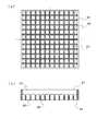
例えば、第2のフィルタプレートの細孔を、図7の(a)および(b)平面模式図に示すように、細孔(28,38)の直径は同じであるが、両プレート(27,37)で数を変えることで圧力損失を変えることができる。ここでは、(a)のフィルタプレート27の高圧損型に対して、細孔数を増やすことで(b)の低圧損型のフィルタプレート37が得られる。
【0049】
なお、第2のフィルタプレートの細孔形状としては、円形が設計、製造上簡便であるが、これに限らず、図8(a)のような楕円形状細孔48、図8(b)のような四角形状細孔58、また図8(c)のような長方形状細孔68、図8(d)のよう多角形状細孔78等いずれの形状であっても良い。
【0050】
図9に示すように、下流側の第2のフィルタプレート87にも、上流側の第1のフィルタプレート84と同様な複数の金属細板85からスリット状開孔86が形成されるをプレートを使用しても良い。この場合、両者の金属細板85は互いにほぼ直角方向をなすように組み合わせれば、見かけ上格子型の流路88が形成される。この場合でも優れた異物捕捉性能が期待できるのは前述の通りである。
【0051】
なお、本発明ではプレートの強度を勘案して、下流側の第2のフィルタプレートには細孔板を使用することを推奨するが、圧力損失調整の観点から第2のフィルタプレートにスリット板を使用することも異物捕捉性能上問題はない。
【0052】
【発明の効果】
以上説明したとおり、本発明の下部タイプレートによれば、原子炉で使用される燃料集合体において、下部タイプレートに内蔵された異物捕捉用フィルタ部材により冷却材中の混入異物が圧力損失の増大を生じることなく良好に捕捉され、燃料集合体の燃料棒領域への異物侵入が非常に困難であるため、フレッティング等による燃料棒の破損を防止できるという効果がある。
【0053】
また、燃料体の燃料棒配列が変更になった場合でも、燃料棒支持部の構造には相互に影響することなく所定の圧力損失を持たせるように容易に異物捕捉用フィルタ部材の調整変更が行える。
【図面の簡単な説明】
【図1】本発明の一実施の形態による沸騰水型原子炉用燃料集合体の下部プレートを示す模式図であり、(a)は下部タイプレートの概略構成図であり、(b)は下部タイプレート内の異物捕捉用フィルタ部材を冷却材流れの上流側から見た平面図である。
【図2】本発明の異物捕捉用フィルタ部材により異物捕捉状況を説明する模式図であり、(a)はフィルタ部材の平面図、(b)は側断面図である。
【図3】本発明の異物捕捉用フィルタ部材により異物捕捉状況を説明する模式図であり、(a)はフィルタ部材の平面図、(b)は側断面図である。
【図4】本発明の異物捕捉用フィルタ部材により異物捕捉状況を説明する模式図であり、(a)はフィルタ部材の平面図、(b)は側断面図である。
【図5】図1の下部タイプレートの製造方法の一例を示す概略工程図である。
【図6】下部タイプレートの製造方法の他の例を示す概略工程図である。
【図7】本発明の第2のフィルタプレートの他の細孔設計を示す平面模式図である。
【図8】本発明の第2のフィルタプレートの他の細孔設計を示す平面模式図である。
【図9】本発明の異物捕捉用フィルタ部材の他の構成例を示す概略構成図であり、(a)は平面模式図、(b)は即断面図である。
【符号の説明】
1:沸騰水型原子炉用燃料集合体の下部タイプレート
1x:下部タイプレート上部材
1y:下部タイプレート下部材
2:上部支持板
3:異物捕捉用フィルタ部材
4,84:第1のフィルタプレート
5,85;金属細板
6,86:スリット状開孔
7,27,37,87:第2のフィルタプレート
8,28,38,48,58,68,78:細孔
9:開口窓
X:第1と第2のフィルタプレートの間隙幅
11,12,13:異物
88:格子状流路[0001]
BACKGROUND OF THE INVENTION
The present invention relates to a lower tie plate of a boiling water reactor fuel assembly, and more particularly to a lower tie plate provided with filter means for trapping foreign matter and filtering a coolant.
[0002]
[Prior art]
A general fuel assembly of a boiling water reactor (BWR) has a rectangular tube shape with a plurality of fuel rods arranged in a bundle of square lattices and upper and lower ends supported by an upper tie plate and a lower tie plate. It is housed in a channel box. A bundle of fuel rods usually contains a small number of water tubes consisting of hollow tubes in the center, and is square-lattice spaced from each other by spacer grids arranged at predetermined intervals at a plurality of locations between the upper and lower tie plates. Supported by the array.
[0003]
After these fuel assemblies are loaded into the reactor core, the coolant is introduced from the coolant inlet at the lower end of the lower tie plate, flows between the fuel rods, and flows out from above the upper tie plate. It will circulate in the furnace as the furnace primary coolant. However, during such coolant circulation, foreign matter such as metal pieces mixed in the plant flows into the channel box together with the coolant, and particularly fine foreign matter enters the gap between the spacer grid and the fuel rods. There is a risk of causing damage due to abnormal wear on the surface and causing fuel failure. Therefore, it is considered to provide a filter means in the lower tie plate to capture foreign matter mixed in the coolant and prevent entry into the fuel rod side.
[0004]
For example, in Japanese Patent Application Laid-Open No. 11-23766, a grid portion that is a support portion for each fuel rod lower end plug at the upper portion of the lower tie plate is replaced with a plate portion that is simply a lattice shape. A fuel rod insertion hole peripheral region that has been provided with pores is disclosed.
[0005]
However, such a method in which the lower tie plate grid portion and the foreign matter catching portion are integrally provided is effective for catching foreign matter larger than the pore diameter, but is fretting between the fuel rod and the spacer. The thin wire-like foreign material considered to be the cause of this may be sucked into the pores while moving on the surface of the flat plate and immediately enter the fuel rod region. In addition, since the fuel rod lower end plug support part and the foreign matter trapping part are integrated, it is possible to greatly increase the total coolant flow area and suppress the increase in pressure loss when the strength of the flat plate is taken into consideration. It seems to be difficult to some extent.
[0006]
Japanese Patent Application Laid-Open No. 8-240678 discloses an apparatus provided with a foreign matter capturing mechanism composed of a member having a large number of openings in a flow path formed by a boss and a web without changing the grid of the grid portion. ing. However, in this case, it is necessary to recreate a foreign matter trapping part every time the fuel rod arrangement changes, and since the foreign matter trapping part further enters the flow path formed by the boss and the web, the coolant flow in the grid part The problem of increased pressure loss occurs. In the future, as the number of fuel rods increases as the fuel assembly becomes more highly burned, the cross-sectional area of the flow path further decreases, so that the pressure loss increases and the fuel rod region cools down. If the material is not supplied sufficiently, the soundness of the fuel body may be hindered.
[0007]
Further, JP-A-8-240677 discloses a structure in which a lattice-like flow path is formed by combining two plates immediately below a lower tie plate grid portion. However, in this method, the lattice channel structure itself has the advantage of not increasing the pressure loss of the coolant flow, but at least the downstream plate has a hole for inserting the fuel rod lower end plug, As a result, it is installed so as to be in contact with the lower surface of the grid portion. This is similar to the one disclosed in JP-A-8-240678 described above, and a foreign matter catching portion is provided immediately below a flow path formed by ribs and webs. As a result, the pressure loss in this portion increases, and the coolant is not sufficiently supplied to the fuel rod region, which may impair the soundness of the fuel body.
[0008]
[Problems to be solved by the invention]
In the lower tie plate of a conventional boiling water nuclear reactor fuel assembly, the foreign matter capturing mechanism provided in the lower tie plate is not limited to the above example, and is integrated with the fuel rod support portion or in contact with the fuel rod support portion. The fuel rod arrangement is governed by the structure and arrangement of the fuel rods. In addition to having to remake the stopper support, the number of fuel rods increases and the coolant flow path formed by the boss and web becomes smaller and the flow resistance becomes difficult to adjust to the required value. .
[0009]
Therefore, it is possible to satisfactorily capture the foreign matter mixed in the coolant while ensuring a sufficient coolant flow rate, and prevent the foreign matter from entering the fuel rod region and damaging the fuel rod due to fretting or the like. Moreover, it seems that an excellent foreign matter trapping mechanism that can easily cope with an increase in the number of fuel rods has not yet been realized.
[0010]
In view of the above problems, the object of the present invention can satisfactorily prevent the entry of foreign substances into the fuel rod area, can easily cope with the change of the fuel rod arrangement, and can always ensure a sufficient coolant flow rate. Another object of the present invention is to provide a lower tie plate of a fuel assembly for a boiling water reactor equipped with a foreign matter trapping means capable of easily adjusting the amount of pressure loss.
[0011]
[Means for Solving the Problems]
In order to achieve the above object, the lower tie plate of the boiling water nuclear reactor fuel assembly according to the first aspect of the present invention includes an upper tie plate and a plurality of fuel rods as a bundle of a predetermined square lattice arrangement, In a lower tie plate of a boiling water nuclear reactor fuel assembly supported at both upper and lower ends by a lower tie plate, a flat foreign matter capturing filter member is used as an upper support plate for supporting a lower end plug of the fuel rod. The foreign matter-capturing filter member is disposed at a position below the non-contacting portion, and is disposed on the upstream side of the coolant flow in the lower tie plate and has a predetermined width and thickness in a substantially rectangular frame member. A first filter plate in which a plurality of rows of slit-shaped apertures are formed by horizontally laying a large number of thin metal plates at predetermined intervals, and a first filter plate disposed downstream from the first filter plate. It is a second filter plate formed by providing a large number of pores in the metal plate, in which are combined in parallel to face each other with a predetermined interval.
[0012]
Further, the lower tie plate of the boiling water reactor fuel assembly according to the invention of
[0013]
Further, the lower tie plate of the boiling water nuclear reactor fuel assembly according to the invention of
[0014]
Furthermore, the lower tie plate of the boiling water reactor fuel assembly according to the invention of
[0015]
In the lower tie plate of the present invention, the filter member for capturing foreign matter is disposed upstream of the lower tie plate, and a plurality of metal thin plates are horizontally mounted in parallel at predetermined intervals on a substantially rectangular frame member. A first filter plate in which a plurality of rows of slit-shaped openings are formed, and a second plate in which a large number of pores are provided in a metal plate disposed at a position downstream of the first filter plate. A filter member for capturing foreign matter, which is configured in combination with a filter plate, is built in a position below the upper support plate that supports the lower end plug of the fuel rod of the lower tie plate. The foreign matter that flows into the lower tie plate is the slit-shaped opening of the first filter plate, then the gap between the first and second filter plates, and the second filter plate. Over bets pores, and, because it is captured in a sequential flow path of narrowing filter arrangement, intrusion into the fuel rod region is very difficult.
[0016]
Moreover, according to the configuration of the filter member of the present invention, even if foreign matter is captured on the upstream surface of the first filter plate and the filter is partially blocked, the coolant bypasses the second filter. Since it can flow into the plate side and pass through the pores almost entirely and flow smoothly to the fuel rod side, an increase in coolant flow pressure loss due to clogging can be prevented.
[0017]
Furthermore, the foreign matter capturing filter member according to the present invention is disposed at a lower position not in contact with the upper support plate in the lower tie plate, and the dimensional and strength restrictions due to the fuel rod arrangement of the upper support plate are not directly affected, Since the pressure loss in the lower tie plate can be easily adjusted by simply increasing or decreasing the width and interval of the metal thin plate of the first filter plate and the pore diameter and number of the second filter plate, the upper support Even when the grid shape of the plate, that is, the fuel rod arrangement is changed, the lower tie plate can be easily adjusted so as to have a predetermined pressure loss.
[0018]
Further, the pressure loss is also affected by the distance between the first filter plate and the second filter plate. That is, when the distance between the two filter plates is increased, the pressure loss decreases. When the two filter plates are brought into close contact with each other, the pressure loss increases. Therefore, the pressure loss can be adjusted by adjusting the distance between the two plates.
[0019]
Thus, when adjusting the pressure loss also by adjusting the distance between the two plates, it is necessary to set the pressure loss to a higher value. You may make it adhere | attach. At this time, the foreign matter trapping function due to the gap between the two plates as described above is lost, but in the present invention, the combination of the first filter plate and the second filter plate provides high foreign matter trapping performance. Absent.
[0020]
Note that the position of the filter member for capturing foreign matter in the present invention may be a lower position that does not contact the upper support plate in the lower tie plate as described above, but considering the increase in the pressure loss of the coolant flow due to the filter. In general, it is desirable to arrange the lower tie plate in a position having the largest channel cross-sectional area in the lower tie plate channel.
[0021]
Such a foreign matter capturing filter member may be manufactured separately from the lower tie plate and later incorporated into the lower tie plate. Therefore, not only has high foreign matter capture performance, but also can be easily manufactured with high accuracy without being affected by the fuel rod support, and as described above, design changes and adjustments can be easily made in response to changes in the predetermined pressure loss. In addition, the degree of freedom in design increases when the burnup of the fuel assembly is increased, and the development of a new foreign matter capturing mechanism can be realized at low cost.
[0022]
Further, the shape of the pores of the second filter plate is not limited to a general circle or ellipse, and various shapes such as a polygon, a single-letter slit shape, or a cross slit shape can be employed. Further, such a second filter plate has a simple structure in which a through hole is formed as if a metal flat plate member is punched out. However, the present invention is not limited to this, and a substantially rectangular frame like the first filter plate. You may use what formed the slit-shaped opening horizontally on the metal thin plate to the member. In this case, if the slits are combined so that the longitudinal directions thereof are orthogonal to each other and a mesh-like pore is formed by the lattice-like overlap of both plates, high foreign matter capturing performance can be obtained.
[0023]
However, from the viewpoint of foreign matter capturing performance, the pores of the second filter plate are preferably smaller than the slit-like openings of the first filter plate. Therefore, the second filter plate itself has a large number of pores, which are smaller than the slit-like openings of the first filter plate, rather than forming the pore-shaped flow path by overlapping the first and second filter plates. It is preferable that it has a pore. Therefore, when the second filter plate is constituted by a plurality of thin metal plates, the metal plate may be horizontally arranged in a lattice shape to form a mesh-like flow path.
[0024]
In addition, as a method for incorporating the foreign matter capturing filter member of the present invention below the fuel rod support plate of the lower tie plate, for example, an opening window is formed at a predetermined height position on the side wall surface of the lower tie plate, and the opening Insert a foreign material capturing filter member that has been assembled in advance from the window, slide it into the interior, and fix it by welding, etc., or divide the lower tie plate vertically at a predetermined height position, or separate the upper and lower parts in advance A method of fixing the three members integrally by welding or the like with the filter member sandwiched between the upper and lower portions is simple.
[0025]
DETAILED DESCRIPTION OF THE INVENTION
As one embodiment of the present invention, for capturing foreign matter, which is composed of a combination of a first filter plate having a plurality of rows of slit-shaped openings and a second filter plate having a large number of circular pores A lower plate of a boiling water reactor fuel assembly incorporating a filter member is shown in FIG. FIG. 1A is a schematic configuration diagram of a lower tie plate of the present embodiment, and FIG. 1B is a schematic plan view of a foreign matter capturing filter member in the lower tie plate as viewed from the upstream side of the coolant flow. .
[0026]
In the
[0027]
The
[0028]
The foreign matter capturing
[0029]
Hereinafter, the foreign matter trapping state by the stepwise foreign matter trapping
[0030]
First, as shown in FIG. 2, in the case of the
[0031]
Next, as shown in FIG. 3, in the case of the
[0032]
Here, if the flow passage cross-sectional area of the
[0033]
On the other hand, when the
[0034]
Therefore, the ratio of the probability that foreign matter is sucked into the
[0035]
In addition, when the coolant flow path composed of the slit-shaped
[0036]
In this way, the movement of the
[0037]
Next, as shown in FIG. 4, the flow path width of the slit-
[0038]
However, the
[0039]
As described above, according to the
[0040]
In addition, the pressure loss of the fuel assembly irradiated in the reactor is required to be within a predetermined range, but the fuel rod array of the fuel assembly currently used in the boiling water reactor is While there are 8 rows and 8 columns and 9 rows and 9 columns, the development of a multi-row, multi-column type fuel assembly aimed at further increasing the burnup is underway.
[0041]
If the fuel rod arrangement changes, the pressure loss in the fuel rod region in the fuel assembly also changes, so that the pressure loss in the lower tie plate portion also needs to be changed. Here, if the foreign matter capturing mechanism includes the lower tie plate fuel rod support portion and is provided so as to be flush with or in contact with the same, the structure or dimensions of the foreign matter capture portion each time the fuel rod arrangement changes. However, the provision of such a mechanism between the fuel rod support portions has many limitations in terms of dimensions and strength, and it is a great deal to develop a foreign matter trapping portion corresponding to a new fuel rod arrangement. Time and cost.
[0042]
However, the foreign matter capturing
[0043]
In addition, as a method of incorporating the filter member for capturing foreign matter of the present invention in the lower tie plate, a method having as few steps and parts as possible is desired. For example, one of the simplest procedures is one that can use a lower tie plate formed by a conventional manufacturing method as shown in FIG.
[0044]
That is, as in the prior art, the foreign matter capturing
[0045]
After the foreign matter-capturing
[0046]
In addition to the method using such an opening window, for example, as shown in FIG. 6A, the
[0047]
As described above, it is necessary to determine the design of the filter member for capturing foreign matter so that the predetermined coolant flow pressure loss according to the design of the fuel rod assembly is obtained. By adjusting the pressure loss, the pressure loss can be easily adjusted.
[0048]
For example, the pores of the second filter plate are the same in the diameter of the pores (28, 38) as shown in the schematic plan views of FIGS. The pressure loss can be changed by changing the number in 37). Here, the low pressure loss
[0049]
The pore shape of the second filter plate is simple in design and manufacture, but is not limited to this, and is not limited to this. The
[0050]
As shown in FIG. 9, the
[0051]
In the present invention, in consideration of the strength of the plate, it is recommended to use a pore plate for the second filter plate on the downstream side, but from the viewpoint of pressure loss adjustment, a slit plate is used for the second filter plate. There is no problem in using the foreign matter.
[0052]
【The invention's effect】
As described above, according to the lower tie plate of the present invention, in the fuel assembly used in the nuclear reactor, the foreign matter trapped in the lower tie plate causes the foreign matter in the coolant to increase the pressure loss. It is possible to prevent the fuel rods from being damaged due to fretting or the like because it is very difficult to capture the foreign matter and it is very difficult to enter the foreign matter into the fuel rod region of the fuel assembly.
[0053]
Even when the fuel rod arrangement of the fuel body is changed, the foreign matter capturing filter member can be easily adjusted and changed so as to have a predetermined pressure loss without affecting the structure of the fuel rod support portion. Yes.
[Brief description of the drawings]
FIG. 1 is a schematic diagram showing a lower plate of a boiling water reactor fuel assembly according to an embodiment of the present invention, (a) is a schematic configuration diagram of a lower tie plate, and (b) is a lower part of the lower tie plate. It is the top view which looked at the filter member for a foreign substance capture in a tie plate from the upstream of a coolant flow.
FIGS. 2A and 2B are schematic views for explaining a foreign matter capturing situation by the foreign matter capturing filter member of the present invention, wherein FIG. 2A is a plan view of the filter member, and FIG.
FIGS. 3A and 3B are schematic views for explaining a foreign matter capturing situation by the foreign matter capturing filter member of the present invention, wherein FIG. 3A is a plan view of the filter member, and FIG.
FIGS. 4A and 4B are schematic diagrams for explaining a foreign matter capturing situation by the foreign matter capturing filter member of the present invention, wherein FIG. 4A is a plan view of the filter member, and FIG.
5 is a schematic process diagram showing an example of a method for manufacturing the lower tie plate in FIG. 1. FIG.
FIG. 6 is a schematic process diagram showing another example of a method for producing a lower tie plate.
FIG. 7 is a schematic plan view showing another pore design of the second filter plate of the present invention.
FIG. 8 is a schematic plan view showing another pore design of the second filter plate of the present invention.
FIGS. 9A and 9B are schematic configuration diagrams showing another configuration example of the foreign matter capturing filter member of the present invention, wherein FIG. 9A is a schematic plan view, and FIG.
[Explanation of symbols]
1: Lower tie plate of boiling water reactor fuel assembly
1x: Lower tie plate upper member
1y: Lower tie plate lower member
2: Upper support plate
3: Filter member for capturing foreign matter
4, 84: first filter plate
5,85; Metal thin plate
6,86: slit-shaped opening
7, 27, 37, 87: second filter plate
8, 28, 38, 48, 58, 68, 78: pores
9: Open window
X: gap width between the first and second filter plates
11, 12, 13: Foreign matter
88: Lattice flow channel
Claims (4)
Translated fromJapanese平板状の異物捕捉用フィルタ部材を、前記燃料棒の下部端栓を支持する上部支持板に接しないこれより下方位置に内蔵し、
前記異物捕捉用フィルタ部材は、下部タイプレート内の冷却材流れの上流側に配置され、略四角形状の枠部材に予め定められた幅および厚さを有する多数の金属細板を所定間隔で平行に横架することによって複数列のスリット状開孔が形成されている第1のフィルタプレートと、該第1のフィルタプレートから下流側に配置され、金属板に多数の細孔を設けてなる第2のフィルタプレートとが、所定間隔を持って互いに平行に対面状態で組み合わされていることを特徴とする沸騰水型原子炉用燃料集合体の下部タイプレート。In the lower tie plate of a boiling water reactor fuel assembly in which a large number of fuel rods are supported at upper and lower ends by upper and lower tie plates as a bundle of a predetermined square lattice arrangement,
A flat plate-like foreign matter capturing filter member is incorporated at a position below the upper support plate that supports the lower end plug of the fuel rod,
The foreign matter trapping filter member is arranged on the upstream side of the coolant flow in the lower tie plate, and a large number of thin metal plates having a predetermined width and thickness are parallel to the substantially rectangular frame member at predetermined intervals. A first filter plate in which a plurality of rows of slit-shaped openings are formed by being horizontally mounted, and a first filter plate disposed downstream from the first filter plate, wherein a plurality of pores are provided in the metal plate. A lower tie plate of a fuel assembly for a boiling water reactor, wherein two filter plates are combined in a face-to-face state with a predetermined distance in parallel.
平板状の異物捕捉用フィルタ部材を、前記燃料棒の下部端栓を支持する上部支持板に接しないこれより下方位置に内蔵し、
前記異物捕捉用フィルタ部材は、下部タイプレート内の冷却材流れの上流側に配置され、略四角形状の枠部材に予め定められた幅および厚さを有する多数の金属細板を所定間隔で平行に横架することによって複数列のスリット状開孔が形成されている第1のフィルタプレートと、該第1のフィルタプレートから下流側に配置され、金属板に多数の細孔を設けてなる第2のフィルタプレートとが、互いに密着した対面状態で組み合わされていることを特徴とする沸騰水型原子炉用燃料集合体の下部タイプレート。In the lower tie plate of a boiling water reactor fuel assembly in which a large number of fuel rods are supported at upper and lower ends by upper and lower tie plates as a bundle of a predetermined square lattice arrangement,
A flat plate-like foreign matter capturing filter member is incorporated at a position below the upper support plate that supports the lower end plug of the fuel rod,
The foreign matter trapping filter member is arranged on the upstream side of the coolant flow in the lower tie plate, and a large number of thin metal plates having a predetermined width and thickness are parallel to the substantially rectangular frame member at predetermined intervals. A first filter plate in which a plurality of rows of slit-shaped openings are formed by being horizontally mounted, and a first filter plate disposed downstream from the first filter plate, wherein a plurality of pores are provided in the metal plate. A lower tie plate of a fuel assembly for a boiling water reactor, wherein two filter plates are combined in a face-to-face contact state.
Priority Applications (1)
| Application Number | Priority Date | Filing Date | Title |
|---|---|---|---|
| JP2000249626AJP3778787B2 (en) | 2000-08-21 | 2000-08-21 | Lower tie plate of boiling water reactor fuel assembly |
Applications Claiming Priority (1)
| Application Number | Priority Date | Filing Date | Title |
|---|---|---|---|
| JP2000249626AJP3778787B2 (en) | 2000-08-21 | 2000-08-21 | Lower tie plate of boiling water reactor fuel assembly |
Publications (2)
| Publication Number | Publication Date |
|---|---|
| JP2002062392A JP2002062392A (en) | 2002-02-28 |
| JP3778787B2true JP3778787B2 (en) | 2006-05-24 |
Family
ID=18739344
Family Applications (1)
| Application Number | Title | Priority Date | Filing Date |
|---|---|---|---|
| JP2000249626AExpired - Fee RelatedJP3778787B2 (en) | 2000-08-21 | 2000-08-21 | Lower tie plate of boiling water reactor fuel assembly |
Country Status (1)
| Country | Link |
|---|---|
| JP (1) | JP3778787B2 (en) |
Families Citing this family (9)
| Publication number | Priority date | Publication date | Assignee | Title |
|---|---|---|---|---|
| JP4006678B2 (en) | 2001-12-25 | 2007-11-14 | 株式会社グローバル・ニュークリア・フュエル・ジャパン | Nuclear fuel assembly lower tie plate and assembly method thereof |
| DE102004059195B3 (en)* | 2004-12-09 | 2006-02-23 | Framatome Anp Gmbh | Fuel element for a boiling water nuclear reactor, comprises a foot, a sieve plate, a fuel element head and a bundle of longitudinal fuel rods |
| US8317035B2 (en)* | 2004-12-30 | 2012-11-27 | Global Nuclear Fuel-Americas, Llc. | Debris filter |
| CN109935362B (en)* | 2017-12-19 | 2024-05-14 | 中国原子能科学研究院 | Fuel assembly, lower tube seat thereof and bottom device of fuel assembly |
| CN109935363B (en)* | 2017-12-19 | 2024-05-10 | 中国原子能科学研究院 | Fuel assembly and bottom device thereof and bottom tube seat applied to bottom device |
| CN109935361B (en)* | 2017-12-19 | 2024-05-31 | 中国原子能科学研究院 | Square double-sided cooling annular fuel assembly |
| CN115171921B (en)* | 2022-05-11 | 2025-03-14 | 中国原子能科学研究院 | A foreign body prevention net and fuel assembly |
| CN115206556B (en)* | 2022-06-10 | 2024-10-18 | 中国原子能科学研究院 | Square box type fuel assembly |
| CN115985530B (en)* | 2022-11-28 | 2025-09-16 | 中国核动力研究设计院 | Single-channel rectangular narrow-slit hydraulic test body for reactor plate type fuel assembly |
- 2000
- 2000-08-21JPJP2000249626Apatent/JP3778787B2/ennot_activeExpired - Fee Related
Also Published As
| Publication number | Publication date |
|---|---|
| JP2002062392A (en) | 2002-02-28 |
Similar Documents
| Publication | Publication Date | Title |
|---|---|---|
| JP5778883B2 (en) | Method for filtering debris shields and debris for upper tie plates in nuclear fuel bundles | |
| KR920000322B1 (en) | Debris Capture Strainer Grid | |
| JPH03205590A (en) | Filter plate associated with lower connector of fuel rod cluster in atomic reactor | |
| EP1868208B1 (en) | Nuclear fuel rod spacer assembly with debris guide | |
| US6901128B2 (en) | Foreign matter filter for fuel assembly in pressurized water reactor | |
| JP3778787B2 (en) | Lower tie plate of boiling water reactor fuel assembly | |
| US4919883A (en) | Lower end fitting debris collector and end cap spacer grid | |
| US8824621B2 (en) | Debris filter for use in a nuclear fuel assembly | |
| JP5599799B2 (en) | A filter for catching small pieces in the reactor coolant | |
| JP7568653B2 (en) | DEBRIS FILTER DEVICE FOR A BOTTOM NOZZLE OF A NUCLEAR FUEL ASSEMBLIES AND BOTTOM NOZZLE COMPRISING THE SAME - Patent application | |
| JP2020511649A (en) | Lower nozzle of nuclear fuel assembly for filtering foreign matter | |
| KR101826045B1 (en) | Bottom nozzle providing with insertable filtering device for nuclear fuel assembly | |
| KR101490968B1 (en) | Nuclear fuel assembly tie plate, upper nozzle and nuclear fuel assembly comprising such a tie plate | |
| JP5322439B2 (en) | Nuclear fuel assembly | |
| JP3977969B2 (en) | Fuel assembly | |
| JP2000284080A (en) | Fuel assemblies for boiling water reactors | |
| ES2992519T3 (en) | Nuclear fuel assembly bottom debris filter and manufacturing process for such debris filter | |
| JPH09101385A (en) | Lower nozzle of PWR fuel assembly | |
| TW201312590A (en) | Nuclear fuel assembly tie plate, upper nozzle and nuclear fuel assembly comprising such a tie plate | |
| JP4090940B2 (en) | Lower tie plate, its assembly method and fuel assembly | |
| ES2992486T3 (en) | Nuclear fuel assembly and method of manufacturing said nuclear fuel assembly | |
| JP2003098284A (en) | Fuel inlet structure and fuel assembly | |
| JP2012117921A (en) | Multistage-type foreign matter filter | |
| JP4282785B2 (en) | Fuel assembly | |
| JP2001004771A (en) | 17x17 type PWR fuel assembly foreign matter countermeasure lower nozzle |
Legal Events
| Date | Code | Title | Description |
|---|---|---|---|
| A977 | Report on retrieval | Free format text:JAPANESE INTERMEDIATE CODE: A971007 Effective date:20050201 | |
| A131 | Notification of reasons for refusal | Free format text:JAPANESE INTERMEDIATE CODE: A131 Effective date:20050302 | |
| RD02 | Notification of acceptance of power of attorney | Free format text:JAPANESE INTERMEDIATE CODE: A7422 Effective date:20050523 | |
| TRDD | Decision of grant or rejection written | ||
| A01 | Written decision to grant a patent or to grant a registration (utility model) | Free format text:JAPANESE INTERMEDIATE CODE: A01 Effective date:20060222 | |
| A61 | First payment of annual fees (during grant procedure) | Free format text:JAPANESE INTERMEDIATE CODE: A61 Effective date:20060228 | |
| R150 | Certificate of patent or registration of utility model | Free format text:JAPANESE INTERMEDIATE CODE: R150 | |
| FPAY | Renewal fee payment (event date is renewal date of database) | Free format text:PAYMENT UNTIL: 20090310 Year of fee payment:3 | |
| FPAY | Renewal fee payment (event date is renewal date of database) | Free format text:PAYMENT UNTIL: 20120310 Year of fee payment:6 | |
| FPAY | Renewal fee payment (event date is renewal date of database) | Free format text:PAYMENT UNTIL: 20150310 Year of fee payment:9 | |
| R250 | Receipt of annual fees | Free format text:JAPANESE INTERMEDIATE CODE: R250 | |
| LAPS | Cancellation because of no payment of annual fees |