JP3777261B2 - Optical network - Google Patents
Optical networkDownload PDFInfo
- Publication number
- JP3777261B2 JP3777261B2JP35480198AJP35480198AJP3777261B2JP 3777261 B2JP3777261 B2JP 3777261B2JP 35480198 AJP35480198 AJP 35480198AJP 35480198 AJP35480198 AJP 35480198AJP 3777261 B2JP3777261 B2JP 3777261B2
- Authority
- JP
- Japan
- Prior art keywords
- node
- switching
- wavelength
- optical
- transmission
- Prior art date
- Legal status (The legal status is an assumption and is not a legal conclusion. Google has not performed a legal analysis and makes no representation as to the accuracy of the status listed.)
- Expired - Fee Related
Links
Images


Landscapes
- Data Exchanges In Wide-Area Networks (AREA)
- Use Of Switch Circuits For Exchanges And Methods Of Control Of Multiplex Exchanges (AREA)
- Optical Communication System (AREA)
Description
Translated fromJapanese【0001】
【発明の属する技術分野】
波長多重および空間多重を用い、ダイナミックな波長切替および空間切替による通信路設定が可能な大容量光ネットワークに関する。
【0002】
【従来の技術】
情報化の進展に応じて、ネットワークの大容量化が求められている。光通信を用いたネットワークでは、波長多重技術を用いての大容量化が研究開発されている。しかし、現状の波長多重技術では、100波程度の多重しかできないため、情報通信の需要の伸びにすぐ対応できなくなると考えられる。
【0003】
また、現在のところは波長可変光源や波長可変フィルタなどの性能に制限があるため、フレキシブルな通信設定ができる光ネットワークを実現しようとすると、さらに利用可能な波長数などが制限されてしまう。そこでこの様なネットワークをさらに多重化することにより将来求められる大容量化に対応することが考えられる。
【0004】
【発明が解決しようとする課題】
例えば、波長多重ネットワークを空間的に多重したネットワークの例を図3に示す。
【0005】
このネットワークの各光リングでは、光波長多重技術を用いて同時に複数の波長の光信号を使える様にすることにより、光リング上で複数の通信が同時に行える。この様な特徴を持つ光リングが空間的に多重されてマルチリングネットワークを構成している。光リングと波長の組合せにより指定される論理的な通信路をチャネルと呼ぶことにすると、このネットワークでは、それぞれのノードが複数あるチャネルの中から一つ選んで、それぞれ通信を行なう。各ノードは、チャネルを選択するために空間的に異なるリングの切替え機能と波長切替え機能を持つ光送受信器を備え、通信の相手先ノードを変える度に前記光送受信器を用いて使用チャネルを切替える。
【0006】
しかし、この様なネットワークを実現するためには、いくつかの問題点がある。
【0007】
第一の問題点は、前記空間切替え手段と波長切替え手段は全く独立した切替え手段であるが、その切替え時間に差がでる。例えば、空間切替を行なう間に、波長切替えは何度も行なえる様な場合、空間切替えの時間により、通信時間に比しての切替えに費やす時間、つまり光送受信器の利用効率が決まり、高速な波長切替えの利点が活かされない。
【0008】
第二の問題点は、各ノードはデータを転送するために、必ず相手ノードとの間で、使用するチャネルを決定するための通信設定を行なう必要があるが、少量のデータの転送等にまで、時間や処理能力をこの設定に費やすことになり、非効率的である。
【0009】
第三の問題点は、大容量化に伴い前記通信設定のために費やす通信が増加し、複数の通信設定通信がノードで衝突したり、処理順序が不適切になることがある。
【0010】
第四の問題点は、各ノードは、通信の相手先ノードを変える度に相手と合わせて使用チャネルを切替えるが、その切替え先チャネルとなる使用可能なチャネルを選択する処理や、当該使用チャネルを相手先と一致して正しく選択するためのノードの制御部での処理が重い。
【0012】
これらの問題は、光ネットワークの多重による大容量化において生じるもので、本発明は、前記第一の問題と第四の問題の解決を図るものである。
【0013】
【課題を解決するための手段】
本発明による光ネットワークは、複数の光伝送路を利用する空間多重および波長多重を併用した空間および波長の組合せで指定されるチャネルを介して通信を行う光ネットワークであって、前記光ネットワークに所属して通信を行うノードは、送信波長切替手段と、この送信波長切替手段からの出力光を変調し信号光を出力する変調手段とを有するバースト光送信手段と、このバースト光送信手段から出力される信号光が送出される光伝送路を設定する送信側空間切替手段と、 前記ノードの受信用に割り当てられた波長が含まれる受信光信号を伝送する一または複数の所定の光伝送路に接続され、前記受信光信号の中から前記ノードの受信に割り当てられた波長をそれぞれ選択的に抜き出す受信波長切替手段と、前記所定の光伝送路が複数であるときに設けられ、前記受信用波長切替手段によりそれぞれ選択的に抜き出された波長の光信号を選択する受信用空間切替手段と、この受信用空間切替手段からの出力、または前記所定の光伝送路が一であるときには前記受信波長切替手段の出力を受信し、電気信号に変換するバースト光受信手段と、通信予定に従って、前記送信波長切替手段と、前記受信波長切替手段と、前記送信空間切替手段と、前記所定の光伝送路が複数であるときは前記受信用空間切替手段とを制御するとともに他ノードの制御情報を交換する制御手段とを有し、
この制御手段は、前記ノードが送信先ノードを時間とともに変えながら行う一連の通信を行うにあたって、
前記送信波長切替手段の波長切替速度と、前記送信空間切替手段の空間切替速度とで、いずれか切替時間が長い第1の切替手段の切替対象のうち、前記送信先ノードで受信可能な状態にあるそれぞれの第1の切替手段の切替対象ごとに前記ノードからの送信データが存在する送信先ノードについて第1の切替手段の切替えスケジュールを作成し、この切替えスケジュールにおける各切替段階について前記ノードからの送信データが存在する送信先ノードについて、切替時間が短い第2の切替手段の切り替えスケジュールを作成することによって、前記通信予定を計画する。
【0014】
ここで、第1の切替手段、第2の切替手段は、空間切替手段または波長切替手段である。また、第1の切替手段の切替対象、第2の切替手段の切替対象は、空間または波長である。
【0015】
また、所定の光伝送路が一であるときは、当該通信の受信側ノードは、接続されるリングが固定されているため、使用可能チャネルの組合せが減り、使用チャネルを決定するための処理が効率化される。
【0016】
さらに、前記第1の切替手段、すなわち切替時間が長い切替手段は前記空間切替手段である。
以上の解決手段により、ノードは要求された特定の通信品質を保ちつつ、遅い切替え時間を持つ切替え手段の利用を最小限に抑えるようにチャネル切替え順序が決定されるので、その結果、稼働時間中のチャネル切替えが占める時間が最適化された光ネットワークが提供することが可能となる。
【0025】
【発明の実施の形態】
以下に、図を用いて本発明の実施例を説明する。
【0026】
図2に、本発明が適用される光ネットワークの例を示す。ノードAからXがネットワークコアに接続されてネットワークを構成している。このネットワークを介して、ノード相互で情報が転送される。各ノードには端末が接続されているかもしれないし、ルータやスイッチが接続されているかもしれないし、さらに他のネットワークが接続されているかもしれない。いずれにしろそれらで生じた情報が図2に示したネットワークを介して、他の場所へ転送される。
【0027】
前記ネットワークの具体的な例の一つが、図3の#1〜#4の複数の光リングのサブネットワークにより構成されているネットワークである。各光リングでは、光波長多重技術を用いて同時に複数の波長の光信号を使える様にすることにより、光リング上で複数の通信が同時に行える。この様な特徴を持つ光リングが空間的に多重されてネットワークを構成している。光リングと波長の組合せにより指定される論理的な通信路をチャネルと呼ぶことにすると、このネットワークでは、それぞれのノードが複数あるチャネルの中から一つ選んで、それぞれ通信を行なっている。
【0028】
各ノードには、あらかじめ割り当てられたリングと波長の組合せ(チャネル)があり、そのチャネルを固定的に受信する光受信器が備えられている。また、ネットワーク内の全ノードに信号を伝送出来るように、接続リングと送信光波長を可変できる光送信器も備える。そして各ノードはこの光送信器を用いて、第一の相手ノード宛に第一の光リングの第一の光周波数であるデータを送出すると、光リングや波長を切替えて第二の相手ノード宛に次のデータを送出する。このように、次々と異なる相手へデータを転送していくので、送信するノードと受信するノードの組合せはダイナミックに変化する。
【0029】
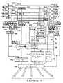
図1にノードの構成例を示す。ノードは、4つの光リングに、4つのカプラ104-1〜4と空間スイッチ110を介して接続された光送信器107と、4つのうちの一つのリングに波長選択器123を介して接続された光受信器106により光信号の入出力を行なう。これら送受信器の入出力と図示されていない前記ノードのローカルへの入出力インターフェースとが、ルーティング部115を介して接続されている。またノードは、これら光送受信器、ルーティング部などを管理する制御部111を持つ。さらに、前記制御部111による情報転送を主な目的としたデフォルトチャネル光送受信器108および109が、WDM(Wavelength Division multiplex)カプラ105-1,2を介して光リング103-1に接続されている。
【0030】
前述したノードの光送信器107は、波長可変光源121を持つ。その光出力は、変調器122により情報が変調されたのち、空間切替型光スイッチ110を介していずれかの光リングに接続される。この波長可変光源121及び空間スイッチ110は制御部111により制御される。光受信部は、データが転送されてくるリングからノードに割り当てられている光周波数を選択する波長選択器123により抜き出された光信号をバースト受信に対応した光受信器106で受信、電気信号に変換する。そののち、ヘッダ処理部117でヘッダ処理などを行ない、取り出された情報を出力する。ノードは、ネットワークの持つ伝送容量をより有効に利用したり、マルチキャスト通信対応を容易にするため、光送信部や光受信部を複数持つ場合もあり、また、その場合に送信部と受信部が同じ個数でなくとも良い。
【0031】
またノードには、以上説明したデータ送受信用のメイン光送受信器の他に、ネットワークの制御・管理情報や小容量のデータ通信の伝送に主に使われるデフォルトチャネル用光送受信器108,109を備える。図1に示す例では、デフォルトチャネル用送信器109が、波長がλ0固定で、光リング#1(103-1)に接続されている。同様にデフォルトチャネル用受信器108も、受信波長がλ0固定で、光リング#1に接続されている。一般にデフォルトチャネルは、ネットワークの状況を把握し、他ノードからの通信設定の要求に応えるために、常に受信しておく必要があるので、少なくともデフォルトチャネル用の光受信部は、メインの光受信器とは兼用しない。また中継する他ノードの通信設定要求のデータを速やかに転送するためには、デフォルトチャネル用の光送信器もメインの光送信器とは兼用しない方が良い。さらに、この周波数λ0をメイン光送受信器の用いる波長とは離れた波長を用いることにより、デフォルトチャネルを分離する波長選択部に低価格の合分波器が使えるメリットがある。例えば、光アンプも多用することになるメイン用のチャネルを1.55μm帯に設定し、一方デフォルトチャネルを1.3μm帯に設定する。また、構内網などファイバ資源が十分にある場合は、デフォルトチャネル用のファイバを独立させると、さらに合分波器さえ不要になり、システムが簡便化される。なおデフォルトチャネルに対して、メインの光送受信器が通信を行なうチャネルをバイパスチャネルとも呼ぶ。
【0032】
バイパスチャネルによる通信は、例えば、Yoo,M.らによる``A High Speed Protocol for Bursty Traffic in Optical Networks'', (SPIEVol.3230,pp.79-90,Nov. 1997)に紹介されている ''tell-and-go''設定方式を用いる。この場合、各通信は図4に示す次の手順で行なわれる。例えば、ノードAがノードJにデータを伝送する場合、まずノードAは、ノードJ宛にデータを転送する旨をノードJおよび途中ノードに知らせる予告パケット140を送出する。予告パケットは、ネットワークのデフォルトチャネルに送出される。デフォルトチャネルは、ネットワークに接続する全ノードが常に送受信できる状態にいる特別なチャネルである。
【0033】
デフォルトチャネルを流れるパケットは必ずリング上の隣のノードに受信され、そこで予告パケットに示されている通信予定が既に予約済みの他の通信を邪魔しないか確認した上で、当該通信予定に必要なそのノードでの予約を行なう。これらの処理後、そのノードが最終ノードでなければ予告パケットを次のノードに転送される。従って、各中継ノードでは、処理時間152が必要となる。ノードAを出た予告パケット140は、ノードBで前記処理を行なったのち予告パケット141として送出され、ノードC、ノードDとこれを繰り返して、最後にノードJに到着する。
【0034】
ノードJは予告パケット149を受けとり、ノードAからの伝送を受信できるかどうかを判断し、受け取れる場合は、バイパスチャネル用光受信器で、ノードAからのデータを待つ。ノードAは、予告パケットを送出後、ある時間t1(153)をおいて、それまでに予告失敗を告げるパケットが戻ってこない限り、バースト状パケット150を一方的に送り出すことになっている。従って、ノードJには、相当時間の経過後、ノードAからのバースト状パケットが届く。また、予告パケットにもt1に関する情報が含まれており、それを基にノードJでパケット到着のタイミングも推測できる。それに合わせて、ノードJは受信準備ができる。例えば、光受信器では送信ノードAからの過去の通信時に保存しておいた受信ゲインの設定やクロックの同期位相情報などを受信器の初期値として設定することにより、バースト受信における初期引き込み時間の短縮を図る。また、必要なバッファ領域の確保やルーティング能力の確保などもこの時点で行なわれると、スムーズなバースト/パケット処理が実現できる。
【0035】
次に、さらに具体的な例と効果について説明する。前記の様にして通信を行なうため、ノードは送信に際して、相手先ノードに合わせて、常にリングと波長を選択することになる。バイパス通信用送信部では、この選択を上述のとおり波長切替と空間切替の2つの独立した切替え手段を用いて行なう。ところが、第一の問題として前記したように、それぞれの手段の切替えに要する時間が著しく異なる。光送信部の波長切替えは、Distributed Bragg Reflector型半導体レーザ(DBR-LD)を光源に用いることにより、その波長制御電極にかける電流の切替えに応じて、マイクロ秒オーダの速さで行なわれる。一方、空間切替えは、ファイバの接続部をピエゾ素子により機械的に動かすスイッチを用いることにより、ピエゾ素子にかける電圧でファイバ出力のポートが決まるが、この切替え速度はミリ秒オーダである。そこで各ノードの制御部は、一度空間切替を行なうと、当該リングネットワークで行なうことができる通信をできるだけやってしまい、その後で初めて、空間切替えを行なう。こうすることにより、空間切替の頻度を減らして時間の有効利用を行なうことができる。
【0037】
各ノードの制御部が行なう通信相手の順番を決定するスケジューリングには、ノード内に蓄積される相手先別データ量や相手先別のサービス予約状況や相手先ノードの負荷の具合が考慮される。ノードはネットワークの外側に接続されている機器や他のネットワークから来るいろいろな通信パケットを受信すると、まず送り先を判定する。次に、メインのバイパスルートで転送するパケットか、デフォルトチャネルで転送するパケットかを判別する。デフォルトチャネルで転送する場合は、パケットは、デフォルトチャネル送信器に接続するバッファに一時蓄えられ、このバッファのパケットは、逐次デフォルトチャネルに送出される。一方バイパスルートで転送する場合は、送り先ノードごとに分類されたキューに貯められる。場合によっては、同一の送り先の中で、更にサービス毎、フロー毎にキューを分類して貯められることもある。これらの分類は、多くのQoS(Quality of Service)の様に通信ユーザからの要求により設定される場合と、IPルータで用いられているタグスイッチングの様にネットワーク内の効率化の目的でノードにより自主的に設定される場合がある。これらの設定の起動/終了は、既存のプロトコルに従った実装を、ルーティング部および制御部に施すことにより、それらのプロトコルがそのまま利用できる。また、複数の受信器を持つノードに対してもキューの数は受信器の数には関係無い。スケジューリングを行なう制御部は、これらのバッファへのパケットの蓄積具合をみて、多く蓄えられているバッファの相手先から順番にバイパスチャネルの通信が行なわれる様に通信設定を行なっていく。
【0038】
この際に、ノードの制御部は、前記切替え方式毎の切替え時間の違いを考慮するので、まず、相手先をその所属リング毎に分類する。そして、リング毎の全ての相手先をまとめたバッファの蓄積状況から、まずリング移動のスケジューリングを行なう。さらに、各リング内での各相手先バッファの蓄積状況から相手切替えつまり波長切替えのスケジューリングを行なう。制御部111は、作成したスケジューリングに従い、デフォルトチャネルに予告パケットを送出し、通信設定を順次行なう。ただ、あるリングで通信を設定している時、そのリング上の全ての相手先と通信を設定する訳ではない。バッファに十分な量のパケット、例えば伝送した際のバースト長が波長切替え時間に対して比較し得る位長くなる量以上のパケット、が蓄積されていない場合、その相手先への送出は先送りするかもしれないし、特定のリング上の相手先ばかりバッファが一杯になっていっても、その中で優先度の高いバッファを送出し終えたら、一度、他リングの通信へ切替えるかもしれない。
【0039】
この様にスケジューリングには、平均的にリーズナブルなサービスが実現される様にするというもう一つのポイントがある。帯域、帯域使用効率、遅延、遅延ゆらぎ、パケット廃棄率などの多種多様なサービスファクタの全てを満たす訳ではなく、ノードあるいはネットワークの運用ポリシに従って、実現すべき品質は異なる。たとえば、最大遅延時間を大事なファクタとした場合について説明する。ここで制御部は、ノードを通過するパケットが受ける最大遅延時間をできるだけ短くする様にバイパスチャネルの通信をスケジューリングする。例えば、「ロード(負荷)の高い相手先には、設定失敗を減らすため、早めにt1を十分にとった予告パケットを送っておいて、定期的に通信権を獲得する」、「一定時間経過してもバイパスチャネルを使用するほどパケットが蓄積されなかったバッファでは、バッファ中のパケットを、デフォルトチャネルバッファに移してデフォルトチャネル経由で送出する」、といったルールを適用して、スケジューリングが行なわれる。
【0040】
図5に制御部111での処理手順例を示す。行き先別キューの状況等から、次のT/2時間のリング切替え順序と各リングでの滞留時間を決定する(ステップ161)。当該リングに属するノードのキューで優先度の高いキューに対して、必要な通信時間等の資源を確保する(ステップ162)。残りリング滞留時間を配分し、当該リングに属するノードの間で、キューの状況から波長切替え順序と各波長での滞留時間を決定する(ステップ163)。当該リングで波長を割り当てられなかったノード行キュー内の待機パケットをデフォルトチャネル送信用バッファに移動する(ステップ164)。続いて、最後のリングであるかどうかが判断され、最後でなければステップ162へ進み、最後であればステップ166へ進む。最後のリングの場合には、時間帯t0〜t0+T/2のスケジューリングが終了となる(ステップ166)。そして、処理161〜166を時間T/2毎に繰り返すことにより、キューにおいてパケットが受け得る遅延を最大でTに抑えることができる。そして、空間切替のスケジュールに関わる処理161の後に波長切替のスケジュールに関わる処理162から処理165を光リングの数だけ繰り返すという独立した2段階の手順で構成されており、これにより前述の効果を持った処理が実施される。
【0041】
以上の様に、バッファでの蓄積状況、必要なサービスの確保に加えて、切替え時間の違いを考慮したスケジューリングを行なうことにより、トータルでの通信効率の向上が図られることが、本発明を用いることの最大の利点である。
【0042】
予告パケットは、制御部111により、生成・中継される。スケジュールに従い、相手ノードとその途中のノードに相手ノードにより決まる光リングと波長の組合せのバイパスチャネル使用の予約を行なう。図6に予告パケットの例を示す。予告パケット170には、発信元アドレス、宛先アドレス、実際のデータ送出タイミングを示すt1(173)、パケット持続時間(174)等がデータとして含まれる。またデフォルトチャネルは、他の通常の通信のパケットも流れるので、ヘッダはそれと共通化を図る。たとえば、IPパケットをサービスするネットワークでは、20バイトのIPヘッダ互換部171を用いる。ただし、予告パケットは重要度が高い情報なので、デフォルトチャネル受信器108で電気信号に変換されたのち、セレクタ119によって直ちに他のデータから選別され制御部111に渡される。これは、通常のデータ同様にバッファ経由でルーティング機能を通過させると、輻輳時には大幅な遅延を被り、最悪のケースではパケットが廃棄されることがあるのを防ぐためである。予告パケットだけでなく、ノード同士の制御情報を交換する制御パケットなども同様の取り扱いをする。このため、予告パケットや制御パケットは、ヘッダ内にそれを示すコードが含まれる。例えば図6に示したIPヘッダ互換部171のversion 4形式では、TOSビットあるいはProtocolフィールドが、version 6形式では、Priority フィールドがそのために使われる。この様に既存のプロトコルの優先機能を用いることにより、既存のヘッダ処理プログラムあるいは素子に少しの改良を加えるだけでセレクタが作成できる。制御部は、予告パケットを処理後、自ノードが最終宛先でなければ、前記予告パケット170を中継して次ノードに送る。この次ノードは、宛先ノードに届くための経路上にいる隣ノードであり、本実施例の様にリングネットワークの場合には、宛先に依らず隣ノードは一つしかない。
【0043】
また関連して、制御部が生成する予告パケットや制御パケットをデフォルトチャネル用光送信器109に入力する際も、デフォルトチャネルキューからくる通常データより優先的に送信される様に制御される。
【0044】
制御部111は作成したスケジュールに従い、行き先別キューからデータをバイパスチャネル用光送信器に転送する制御も行なう。まず、予告パケットにより予告した送出時間にキューの内容をバーストにして光送信器から送り出せるタイミングで、キューの内容をヘッダ処理部へ転送する。もし、ノードに再送機能がある場合、バーストは再送される可能性があるので、前記転送時にバッファ上にもデータを残しておく。そして、当該データは、転送後一定時間t2の間に再送を行なわなかった時に、始めてバッファから消去される。IPフォーマットのパケットを扱うネットワークの場合、このヘッダ処理部117へ転送されるデータは、IPパケットが1つ以上縦続に並んだものになる(図7)。このデータをカプセル化するヘッダ互換部182をこのヘッダ処理部117でつける。バイパスチャネルでの通信は、送信ノードと受信ノードで互いに相手のノードのことがすでに分かっており、また途中ノードでは光信号がそのまま通過するだけなので、いわば専用線を用いた通信と同じで、発信/受信ノードアドレス、バーストのデータ形式/プロトコルの記述はヘッダ中に必要ない。またバーストの誤りについては、データである各IPパケット183〜189はそれぞれ誤り検出が出来るので、IPヘッダ互換部182の誤り制御だけが必要である。従って、受信時にバーストの終了位置を決定するのに使われるバースト長を示すフィールドが、IPヘッダ互換部182では最も重要で、このフィールドに誤り訂正のためのフィールドを付加したものが最低限必要なヘッダである。この形式により効率的なデータ転送を行なうことが出来る。
【0045】
ただし、途中ノードでの光伝送監視のために発信/受信ノードアドレスがあった方が良いことや、将来の拡張性のためにオプションを設定できること、デフォルトチャンネルではIPパケットがそのままやりとりされること等から、バイパスチャネルにおいてもIPヘッダを流用するのも自然で、この場合、図7で示したパケット形式181を用いるIPトンネルを利用するのが良い。他のパケットサービス方式に供されるネットワークの場合も同様にできる。また、例えばIPとATMの様に複数のサービス方式が混在するネットワークの場合は前記条件を満たす独自ヘッダが必要とな
る。
【0046】
ヘッダの付加されたバーストは、バイパスチャネル用のバースト光送信器107に入力される。そこで光伝送路に適したスクランブルをかけられ、受信側での同期引き込みに使われるプリアンブルが付加され、変調器122へ入力され、光バーストへと変換される。
【0047】
予告パケットに対して途中ノードまたは相手ノードから不許可パケットが返ってきた場合、ノードは再設定に挑むか通信ノード先を変更して対応しようとする。不許可パケットを受ける頻度が高い場合は、そのリングの負荷(ロード)を高いと判断して、他のリングへ移動する。あるいは、デフォルトチャネルを通る不許可パケットの頻度を測定することによって、リングのロードを判断するかも知れない。この様に、各ノードは、各リングのロードを直接的あるいは間接的に把握して、空いているリングに優先的に接続するようにする。ただし通信が集中するノードへの予告は、不許可の確率が高くなるので、その度に通信を諦めると当該ノードへの通信ができなくなってしまう。そこで、ランダムにあるいは決められたルールに従って、再設定を繰り返し通信できるまで待つ必要がある。
【0048】
また不許可パケットが返ってきた場合に、既に予告パケットからの遅れ時間t1の設定によっては、当該バーストがすでに送出されている場合がある。この時には、当該バーストを構成するデータが既にバッファから消去され、バーストの再送ができない様なシステム構成もあり得る。通常、上位層プロトコルでも再送などの誤り制御機構が備えられており、光ネットワークのレベルで再送しなくてもアプリケーションは動作可能だからこの構成が可能である。
【0049】
この不許可パケットの受信前にバーストを送出してしまう場合にもう一つ問題点がある。それは、不許可にも関わらず送出されたバーストが他の送信を許可された(正確には、不許可でなかった)バーストと衝突して、受信側で許可されたバーストの受信に失敗することである。同じ状況は、不許可パケットが途中で誤りなどにより廃棄された場合やプロテクション機能によるループバックが働いた場合にも生じる。このため受信ノードでは、予告パケットにより設定された時刻になってもバーストが到達しなかったり、あるいは、届いたバーストが再生できなかった場合、当該バーストを送信したと推測されるノードに、バースト転送の失敗を通知する制御パケットをデフォルトチャネルを介して送信すると良い。ただ、バースト通信主体のネットワークなため、再送はデータに著しい遅延を与える。これを避けるために、各ノードで不許可なバースト伝送を廃棄したり、既に光信号がチャネル上を伝送されている時には、重ねては光信号が送出できない様な機能を備えるとより良い。この機能は、例えばバイパス送信器出力を光リングに多重するための空間スイッチとカプラで構成されている部分を音響光学効果フィルタ(AOTF:Acousto Optic tunable filter)で構成すると実現できる。AOTFは、任意の波長を任意の程度で合分波できる機能がある。このAOTFを送信光信号の合波器として用いて同時に必要なチャネルの光信号の一部を抜き出しモニタすることにより、異常時には、前記の様な対策を行なうことができる。
【0050】
前述の様に、他ノードの通信状況に関する知識も効率の良いスケジューリングに役立つ。従って、制御部は、デフォルトチャネルを通過する予告パケットなどから、通信状況を把握する表を作成・管理しておく。この表には、例えば各相手先ノードに、どのノードがいつ通信を行なうかが記録されている。
【0051】
またランダムに発生する通信予約がパケット衝突により失敗する確率を下げるために、各リングは平均負荷が例えば50%以下という状態で動作出来るように、ネットワークは設計される。例えば各リングで使用可能な波長が25波長あり、ノードの総数が100局の場合、4リングで全ノードが波長をフルに活用して通信ができるわけだが、この様な状態をtell-and-go方式で実現するのは難しい。これが、例えばリングを8以上設け、各ノードにも相当の容量が確保できる様に受信器を増設すると、パケットあるいはバースト廃棄率が急激に改善され、通信がスムーズに行なわれる様になる。
【0052】
さらに高負荷ノードは、例えば、複数受信器により複数のリングに従属することにより、各受信器の負荷を下げ、同時に負荷を各リングに均等に分散させる効果も提供する。これにより、tell-and-go方式を用いた回線設定によっても、著しくリング数を増やす必要はなくなる。
【0053】
以上の例では、ノードに備えられたメインの光受信器は、接続される光リングが固定され、さらに受信波長も固定されていた。このため、前に述べた様に送信側ノードでは、通信設定を行なうにあたり、使用可能なチャネルを探して、アレンジする必要がなくなるため、チャネル設定に要する処理が軽減される。特に、本発明が扱うネットワークは波長や空間という次元を複数用いるため、チャネルを指定する波長や空間の組合せ数が多い。このため、問題点の第4として指摘したように使用可能な波長のアレンジやその打合せの処理が重くなる問題があったが、前記の様に、本発明によりこの問題が解決される。さらに、前述の他ノードの通信状況に関する知識や複数の受信器設置による受信器負荷の低減などにより、より効率的なチャネル設定処理が実現できる。
【0054】
本実施例中で用いた切替え手段は、ピエゾ素子によりファイバを駆動する空間スイッチとDBR-LDによる送信波長切替の組合せであるため、波長切替の頻度を空間切替の頻度より高くした。これは当然使用する切替え手段により種々の場合が考えられ、例えば、DBR-LDによる送信波長切替と半導体光ゲート(SOAG:Semiconductor Optical Amplifier Gate)による空間スイッチを用いた光送受信部を構成すると、波長切替がマイクロ秒のオーダで行なわれるのに対して、空間切替がナノ秒オーダと波長切替より十分速く行なわれるようになる。この場合においても、前記実施例での空間切替と波長切替の使い方を入れ換えることにより、本発明の効果が得られる。また、ノード毎に切替え速度の速い切替と遅い切替の組合せがことなる場合でも、速い切替の方を優先的に使うという本発明を適用することにより、効率的な通信が実現される。
【0055】
本発明の第2の実施例として、前記実施例と同じく図3のネットワークにおいて、各ノードのバイパスチャネル用光受信器もリングおよび波長が可変可能な場合について、以下に説明する。この場合、信号を送信するノードと受信するノード、使用リング、使用波長の組合せが、ダイナミックに変化する。
【0056】
図8にノードの構成例を示す。先の実施例におけるノードと異なるのは、バースト光受信器106が制御部111により制御される空間スイッチ110-2と波長選択部123-1〜4を介して、全ての光リングに接続されている点である。このノードでは、バースト光送信器107は、情報を伝送するバイパス通信用の送信部として波長可変光源を持ちその出力が空間切替型光スイッチ110を介して各リングに接続されている。バースト光受信器106は、データが転送されてくる光周波数を選択する各リングの波長選択部で選択された光信号が光スイッチで一つだけ選択され、バースト受信に対応した光受信器で受信、電気信号に変換する。そののち、ヘッダ処理などを行ない、取り出された情報を出力する。ノードは、ネットワークの持つ伝送容量をより有効に使い、マルチキャスト通信にも容易に対応するために、光送信部と光受信部を複数持つ場合もある。また、その場合に光送受信器が同じ個数であるとは限らない。
【0057】
ノードには、このバイパスチャネル用光送受信器の他に、小容量の通信や制御情報の伝送に主に使われるデフォルトチャネル用の光送受信部を備えるのは、前記実施例と同様である。
各通信は図4に示す手順で前記実施例と同様にして行なわれる。
【0058】
予告パケットを受けとったノードJは、ノードAからの伝送を受信できるかどうかを判断し、受け取れる場合は、ノードAが指定してきた波長にバイパスチャネル用光受信器の受信波長を合わせる。すると、ノードAからのバースト状パケットが届く。ノードAは、予告パケットを送出後、ある時間t1をおいて、それまでに予告失敗を告げるパケットが戻ってこない限り、バースト状パケットを一方的に送り出す。ノードJがt1以内に予告パケットを受け取れば、ノードJは、ノードAからのパケットを最初から受信できる。
【0059】
この様にして通信を行なうため、ノードは送受信に際して、常にリングと波長を選択することになる。バイパス通信用送受信部では、この選択を上述のとおり波長切替と空間切替の2つの独立した切替え手段を用いて行なう。ところが、それぞれの手段の切替えに要する時間が著しく異なる。
【0060】
光送信部の場合、波長切替えは、マイクロ秒オーダの速さで行なわれる。一方、空間切替え速度はミリ秒オーダである。そこで各ノードの制御部は、一度空間切替を行なうと、当該リングネットワークで行なうことができる通信をできるだけやってしまい、その後で初めて、空間切替えを行なう。こうすることにより、空間切替の頻度を減らして時間の有効利用を行なうことができる。
【0061】
前記機能を実現するため、各ノードの制御部は、常にどのノードがどのリングで通信を行なっているか、特にその光受信器がどのリングで使われているかをできるだけ把握するように表を管理している。この表は、デフォルトチャネルを流れる前述の通信予告パケットやそれを基に各ノードが作った表をノード間で交換することにより、常に最新状況を反映する様に管理される。また各ノードが、自ノードが利用するリングを変更する度にその存在情報をデフォルトチャネルにブロードキャストする様にすると、各ノードは状況を把握しやすくなるので、さらに良い。ノードの存在情報は、各ノードの送受信器が接続リングを変更する直前と直後に流される。変更直後の情報には、例えば予定滞在時間なども含まれて、そのノードへ通信したいノードが通信スケジュールを決めるのにも役立てられる。そして、この表により各ノードは予告パケットの送り先を決定する。
【0062】
ただ、デフォルトチャネルを流れる予告パケットは、勿論全ノードには伝わらないし、他のノード間での表の交換や各ノードの流す存在情報も全ノードに正しく伝わるとは限らない。このため、表は全てのノードの状況を把握していないかもしれないし、最新の状況を反映していないかも知れない、制御部は、その点も考慮に入れ表の管理や通信スケジュール決定を行なう。例えば予告パケットから得た情報は信頼できるが、ノード間で交換した情報は、既に古くなっているかも知れないので、その点を考慮して表の更改を行なう。これにより、表に基づく通信設定を行なった場合でも、当該通信の成功率が向上する。
【0063】
ここまでに示した様に各ノードが波長切替を優先して通信していく場合、通信しようとしてもいつも同じリング上にいない相手が生じ、この相手を追いかけ続ける状態になる可能性がある。この様な相手には、予告の予約を行なう、あるいは、リングと周波数の両方を指定し、かつ予告パケットとデータパケットの間を十分にとる様にして、予告パケットを送出することにより、追いかけあい状態を減らすことができる。この様に通信要求をかなり早くから予告すると良いが、それでもすでに通信希望のタイミングにどのリングに居るかが決まっている可能性もあるので、デフォルトチャネルを介して相手のスケジュールをあらかじめ得ておくのも良い。
【0064】
デフォルトチャネルでは、小容量の通信もその上で行なうので、ノード数が増えると1チャネルでは容量が足りなくなる。デフォルトチャネルが低負荷、十分低いパケット廃棄率で運用されていないと、予告パケットなどが相手ノードに届かずに途中で消失して通信に失敗するなど、デフォルトチャネルの容量制限でネットワーク全体の利用効率が低減してしまうという問題が生じる。そこで、デフォルトチャネルの容量が不足する場合には、瞬時的なケースに対しては、予告パケットを優先的に伝送し通常データはバッファリングや廃棄により対応する。一方、平均的に不足する場合には、各リングにデフォルトチャネルを設定するマルチデフォルトチャネルの構成が有効である。この場合のノードの構成を図9に示す。デフォルトチャネル用光送受信器108、109は、WDMカプラ105-1〜8と制御部111によりコントロールされる空間スイッチ124-1、2により、全リングのデフォルトチャネルに対して光信号の入出力が可能になっている。ただし依然、デフォルトチャネル用光送受信器108及び109は一つずつしか備えていない。ノードは、各リングでデフォルトチャネルを介して、リングの負荷をチェックしながら通信順序を検討する。リングを切替えたノードは、直後に、接続したことを伝えると共に前にいたリングの通信状況等の情報を知らせるパケットを新しいリング上に放送すると良い。これにより、あるリングでも他リングのほぼ最新の情報が入手でき、他のノードのリング間切替えなどのスケジューリングの参考になる。
【0065】
またデフォルトチャネルを、各リングに分散させることにより、第一の実施例でも触れたデフォルトチャネルとバイパスチャネルの1.3μm/1.55μmの波長多重が同様に使えるので、デフォルトチャネルが安価に構成できる。
【0066】
マルチデフォルトチャネル構成において、ノードが複数のデフォルトチャネル用光送受信器を持つ場合は、多少ノードの光送受信器が高価になるが、さらに通信効率を上げられる。制御部111が、現在通信を行なっているリングの他に、次に切替を予定しているリング、さらにその次のリングのデフォルトチャネル情報も入手できる様になるからである。ネットワークにこの様なノードが数ノードあるだけでも、そのノードが最新の他リング情報を流すことができ、他のノードがリング切替をスケジューリングするのに参考にできる。また、複数のバイパスチャネル用光送受信器106,107を持つノードは、各光送受信器のための制御を行なうために、複数のデフォルトチャネル用光送受信器108,109を持つ必要がある。そしてこの時、同時に前述したリング間での情報交換を助けることができる。
【0067】
図10に示すような構成により、全ノードがマルチデフォルトチャネルの数だけデフォルトチャネル用光送受信器を備えるとさらに良い。各リング用デフォルトチャネル光送受信器108-1〜4,109-1〜4はそれぞれWDMカプラ105-1〜8を介して、いずれかの光リングに接続されている。各送信部108-1〜4は、行き先ノードごとに後述するマルチリンクコネクション制御を行なうML部125-1,2を介してパケットを入力している。また、通常のデフォルトチャネル用の合流器118の後に、前述のML部との間に行き先毎にパケットを振り分ける振分器127も備える。各受信部出力は、発信ノード毎のML部125-3,4を介して合流器126により合流され、セレクタ119に渡される。
【0068】
この場合に生じる前記第三の問題に対しては、簡易で効率的なデフォルトチャネルの利用が実現できる。まず、複数のデフォルトチャネル間に通信を分岐させ、また、複数のデフォルトチャネル間からの通信を合流する機能を備えることにより、ノード間ごとに複数あるデフォルトチャネルをマルチコネクションにより構成された一つのリンクとみなすことができる様になる。従ってノードの制御部は、どの情報を相手先に接続されているどのデフォルトチャネルに流すかを区別する必要が無くなる。各ノードはロードの低いデフォルトチャネルを選んで予告パケットや情報を送出することにより、各デフォルトチャネル間の負荷が分散し、通信呼損率が十分低く保たれ、デフォルトチャネルの性能不足によるネットワーク全体の効率低下が生じ難くなる。そして、マルチリンクプロトコル等の順序制御プロトコルを分岐/合流機能に適用することにより、通信予約の順序の逆転等がなくなり、確実性の高い処理が実現される。また、あるデフォルトチャネルが障害により使用不可になっても、残りのチャネルを活用することにより、障害の影響が無い、信頼性の高いチャネルを実現できる。
【0069】
前記第一、第二の実施例においては、通信設定方式として、「tell-and-go」を用いた例を示してきた。この方式は、手順が簡単である上に、各ノードが独立に自律的にスケジューリングを行なえるため、各ノードの状況に応じて、通信設定が調整・変更できるため、通信負荷の時間的な変化や地理的な偏りに自在に対応でき、また、分散システムであるところからくる部分的な障害に非常に強い利点もある。しかも全く自由にデータを送り出すALOHA方式に比べるとスループットが高い。しかし、ネットワークの負荷が高くなると、急激に通信の衝突が頻発して、ネットワークの効率的な活用ができなくなる。そのため、通信容量の点で十分余裕のあるネットワーク設計が必要となり、コストがかかる問題点もある。
【0070】
一方、前述した技術は通信設定方式には依らない。例えばネットワークの本来の通信容量をより効率的に利用するという点では、あらかじめ全ノードのスケジュールを決めてしまうプリアサイン型の通信設定方式が有効であるが、この場合にも前述した技術は有効である。この方式を用いる場合、ネットワーク全体のスケジューリングを行なうスケジューラが存在し、スケジューラが各ノードの通信要求を集め、それに基づいた全ノードのスケジューリングを刻々と行なっていく。この場合でも、第1および第2の実施例により説明した構成を採ることにより、依然その効果が得られる。
【0071】
まずスケジューラは、ノード(あるいは、各バイパス用光送受信器。以下同様)をリングの数より多い複数のグループに分ける。そして、次にそのグループをいずれかのリングに割り当てていく。さらに各リングの中で、あるグループのノードAから異なるグループのノードBへの通信。と、異なるグループに属するノード間の通信のスケジューリングを行なう。各リングでグループ間の通信のスケジューリングが終了すると、次のグループの組合せを各リングに設定していき、その中でのグループ間の通信をスケジューリングする。これを順次行なっていくが、適宜相手グループが無い時などに、グループ内での通信のスケジューリングも行ない実施する。この時、このグループの組合せ変更が各ノードにとってはリング切替えとなり、グループ間通信中の相手ノード変更が波長切替えとなる。従って、ここでも前記2種類の切替が区別され、リング切替(=空間切替)の頻度を低減する様にスケジューリングが行なわれており、その結果、ネットワークの利用効率が向上する。
【0072】
また、この様に2段階のスケジューリングを行なうことにより、スケジューラは、ノードの数よりはずっと少ないグループ数、グループ内ノード数という常に少ない数の組合せのスケジューリングをするだけで良いので、スケジューラの処理量が大幅に削減される利点もある。
【0080】
【発明の効果】
以上、いくつかの実施例を用いて示した様に、ダイナミックに通信チャネルを設定する大容量光ネットワークにおいて、生じ易い通信容量の非効率的な利用の問題は、本出願で開示した、ノードでの切替順序の設定、マルチリング構成において受信に使用するリングの数を制限する技術などにより解決され、効率的で高信頼なデータ通信が実現できる。
【図面の簡単な説明】
【図1】本発明を説明する光ノードの第一の例のブロック図である。
【図2】本発明が適用される大容量ネットワークの例を示す図である。
【図3】本発明が解決する問題点を示しているマルチリング光ネットワークの例を示す図である。
【図4】マルチ光リングネットワークにおけるポイント−ポイント通信の手順例を示す図である。
【図5】最大バッファ遅延を制御するスケジューリングアルゴリズムの例を示す図である。
【図6】予告パケットのフレーム構成例を示す図である。
【図7】バーストパケットのフレーム構成例を示す図である。
【図8】本発明を説明する光ノードの第二の例のブロック図である。
【図9】マルチデフォルトチャネル対応の光ノードの第一の例のブロック図である。
【図10】マルチデフォルトチャネル対応の光ノードの第二の例のブロック図である。
【符号の説明】
103-1〜4 光リング
106 バースト光受信器
107 バースト光送信器
108 デフォルトチャネル用光受信器
109 デフォルトチャネル用光送信器
110 空間スイッチ
111 制御部
115 ルーティング部
118 合流部
119 セレクタ
123 波長選択部
140 予告パケット
150 バーストデータパケット
170 予告パケットフォーマット
181 バーストパケットフォーマット
124-1,2 空間光スイッチ
125-1〜4 マルチリンクコネクション制御部[0001]
BACKGROUND OF THE INVENTION
Wavelength multiplexingandDynamic wavelength switching using spatial multiplexingandCommunication path setting by space switching is possibleFor large-capacity optical networksRelated.
[0002]
[Prior art]
Along with the progress of computerization, there is a demand for an increase in network capacity. In a network using optical communication, research and development has been conducted to increase the capacity using wavelength multiplexing technology. However, the current wavelength multiplexing technology can only multiplex about 100 waves, so it is considered that it will not be able to respond immediately to the growing demand for information communication.
[0003]
At present, the performance of wavelength tunable light sources, wavelength tunable filters, and the like is limited. Therefore, when an optical network capable of flexible communication settings is realized, the number of wavelengths that can be used is further limited. In view of this, it is conceivable to further increase the capacity required in the future by further multiplexing such a network.
[0004]
[Problems to be solved by the invention]
For example, FIG. 3 shows an example of a network in which wavelength division multiplexing networks are spatially multiplexed.
[0005]
Of this networkIn each light ringBy making it possible to use optical signals of a plurality of wavelengths at the same time using an optical wavelength multiplexing technique, a plurality of communications can be performed simultaneously on the optical ring. Optical rings having such characteristics are spatially multiplexed to constitute a multi-ring network. In this network, a logical channel specified by a combination of an optical ring and a wavelength is called a channel.Each nodeSelect one channel from multiple channels and perform communication with each channel. Each node is provided with an optical transceiver having a spatially different ring switching function and wavelength switching function to select a channel, and switches the channel to be used by using the optical transceiver each time the communication partner node is changed. .
[0006]
However, there are some problems in realizing such a network.
[0007]
The first problem is that the space switching means and the wavelength switching means are completely independent switching means, but there is a difference in the switching time. For example, when wavelength switching can be performed many times during space switching, the time spent for switching compared to the communication time, that is, the utilization efficiency of the optical transceiver, is determined by the time of space switching. The advantage of simple wavelength switching is not utilized.
[0008]
The second problem is that each node must make communication settings to determine the channel to be used with each other node in order to transfer data. , Spending time and processing power on this setting is inefficient.
[0009]
A third problem is that as the capacity increases, the communication spent for the communication setting increases, and a plurality of communication setting communications may collide with each other in a node or the processing order may become inappropriate.
[0010]
The fourth problem is that each time the node changes the partner channel of communication each time the destination node of communication is changed, the process of selecting a usable channel as the switching destination channel, The processing at the node control unit for making a correct selection in accordance with the other party is heavy.
[0012]
These problems occur when the capacity is increased by multiplexing optical networks.Of the first and fourth problemsIt is a solution.
[0013]
[Means for Solving the Problems]
An optical network according to the present invention is an optical network that performs communication through a channel specified by a combination of space and wavelength using a combination of spatial multiplexing and wavelength multiplexing using a plurality of optical transmission paths, and belongs to the optical network. The node that performs communication in this manner is transmitted from the burst light transmission means having the transmission wavelength switching means, the modulation means for modulating the output light from the transmission wavelength switching means and outputting the signal light, and the burst light transmission means. A transmission-side space switching means for setting an optical transmission path through which signal light to be transmitted is connected, and one or a plurality of predetermined optical transmission paths for transmitting a received optical signal including a wavelength allocated for reception by the node A plurality of reception wavelength switching means for selectively extracting wavelengths assigned to reception of the node from the reception optical signal, and a plurality of the predetermined optical transmission lines. A reception space switching means for selecting an optical signal having a wavelength selectively provided by the reception wavelength switching means, and an output from the reception space switching means, or the predetermined light; Burst light receiving means that receives the output of the reception wavelength switching means when the transmission path is one, and converts it into an electrical signal, the transmission wavelength switching means, the reception wavelength switching means, and the transmission space according to a communication schedule Switching means and control means for controlling the reception space switching means when there are a plurality of the predetermined optical transmission lines and exchanging control information of other nodes;
This control means, when performing a series of communications that the node performs while changing the destination node with time,
Of the switching targets of the first switching means having a long switching time, either the wavelength switching speed of the transmission wavelength switching means or the space switching speed of the transmission space switching means is in a state that can be received by the transmission destination node. A switching schedule of the first switching unit is created for a destination node where transmission data from the node exists for each switching target of each first switching unit, and each switching stage in the switching schedule is determined from the node. For the transmission destination node in which transmission data exists, the communication schedule is planned by creating a switching schedule of the second switching means with a short switching time.
[0014]
Here, the first switching means and the second switching means are space switching means or wavelength switching means. The switching object of the first switching unit and the switching object of the second switching unit are space or wavelength.
[0015]
In addition, when the predetermined optical transmission line is one, the communication receiving side node has a fixed ring to be connected, and therefore, the number of combinations of usable channels is reduced, and processing for determining the used channel is performed. Increased efficiency.
[0016]
Furthermore, the first switching means, that is, the switching means having a long switching time is the space switching means.
With the above solution, the node switches the channel switching order so as to minimize the use of switching means having a slow switching time while maintaining the required specific communication quality. It is possible to provide an optical network in which the time occupied by channel switching is optimized.
[0025]
DETAILED DESCRIPTION OF THE INVENTION
Hereinafter, embodiments of the present invention will be described with reference to the drawings.
[0026]
In FIG.The present invention2 shows an example of an optical network to which is applied.nodeAFromXTo the network coreConnected to form a network. Information is transferred between nodes via this network. A terminal may be connected to each node, a router or a switch may be connected, and another network may be connected. In any case, the information generated by them is transferred to another location via the network shown in FIG.
[0027]
One specific example of the network is a plurality of # 1 to # 4 in FIG.Light ringA network composed of sub-networks. Each optical ring can simultaneously perform a plurality of communications on the optical ring by using an optical wavelength multiplexing technique to simultaneously use optical signals having a plurality of wavelengths. An optical ring having such characteristics is spatially multiplexed to form a network. If a logical communication path designated by a combination of an optical ring and a wavelength is called a channel, in this network, each node selects one from a plurality of channels and performs communication.
[0028]
Each node has a ring and wavelength combination (channel) assigned in advance, and is provided with an optical receiver that receives the channel in a fixed manner. In addition, an optical transmitter capable of varying the connection ring and the transmission optical wavelength is provided so that signals can be transmitted to all nodes in the network. Then, each node transmits data that is the first optical frequency of the first optical ring to the first partner node using this optical transmitter, and switches the optical ring and wavelength to the second partner node. The next data is sent out. In this way, since data is transferred to different parties one after another, the combination of the transmitting node and the receiving node changes dynamically.
[0029]
FIG. 1 shows a configuration example of the node. The node is connected to four optical rings via four couplers 104-1 to 104-4 and a
[0030]
The
[0031]
In addition to the main optical transceiver for data transmission / reception described above, the node includes default channel
[0032]
For example, Yoo, M. et al., `` A High Speed Protocol for Bursty Traffic in Optical Networks '', (SPIEVol. 3230, pp. 79-90, Nov. 1997) Use the 'tell-and-go' configuration method. In this case, each communication is performed according to the following procedure shown in FIG. For example, when the node A transmits data to the node J, the node A first sends a
[0033]
The packet that flows through the default channel is always received by the adjacent node on the ring, and it is necessary to confirm that the communication schedule shown in the notice packet does not interfere with other reserved communications. Make a reservation at that node. After these processes, if the node is not the last node, the notice packet is transferred to the next node. Therefore, each relay node requires processing time 152. The
[0034]
The node J receives the
[0035]
nextMore specific examples and effectsWill be described. Since communication is performed as described above, a node always selects a ring and a wavelength in accordance with a destination node when transmitting. The bypass communication transmitter performs this selection using two independent switching means, wavelength switching and space switching, as described above. However, as described above as the first problem, the time required for switching each means is remarkably different. Wavelength switching of the optical transmitter is performed at a speed on the order of microseconds according to switching of the current applied to the wavelength control electrode by using a distributed Bragg reflector semiconductor laser (DBR-LD) as a light source. On the other hand, in the space switching, a fiber output port is determined by the voltage applied to the piezo element by using a switch that mechanically moves the fiber connection portion by the piezo element. This switching speed is on the order of milliseconds. Therefore, once the control unit of each node performs space switching, it performs communication that can be performed in the ring network as much as possible, and then performs space switching only after that. By doing so, it is possible to effectively use time by reducing the frequency of space switching.
[0037]
The scheduling for determining the order of communication partners performed by the control unit of each node takes into account the data amount for each partner stored in the node, the service reservation status for each partner, and the load of the partner node. When a node receives various communication packets coming from a device connected to the outside of the network or another network, the node first determines the destination. Next, it is determined whether the packet is transferred through the main bypass route or the default channel. When transferring on the default channel, the packet is temporarily stored in a buffer connected to the default channel transmitter, and the packet in this buffer is sequentially sent to the default channel. On the other hand, when transferring by the bypass route, it is stored in a queue classified for each destination node. In some cases, queues may be further classified and stored for each service and each flow within the same destination. These classifications are set according to the request from the communication user like many QoS (Quality of Service), and depending on the node for the purpose of efficiency in the network like the tag switching used in the IP router. May be set voluntarily. The activation / termination of these settings can be used as they are by applying the implementation according to the existing protocol to the routing unit and the control unit. Further, the number of queues is not related to the number of receivers even for a node having a plurality of receivers. The control unit that performs scheduling performs communication settings so that communication of the bypass channel is performed in order from the counterpart of the buffer that has been stored in large numbers, in view of how packets are stored in these buffers.
[0038]
At this time, the control unit of the nodeSince the difference in switching time for each switching method is taken into account, first, the counterpart is classified for each belonging ring. Then, the ring movement is first scheduled from the buffer accumulation state in which all the destinations for each ring are collected. Further, scheduling of partner switching, that is, wavelength switching is performed based on the accumulation status of each partner buffer in each ring. In accordance with the created scheduling,
[0039]
In this way, there is another point in scheduling that an average reasonable service is realized. Not all the various service factors such as bandwidth, bandwidth usage efficiency, delay, delay fluctuation, and packet discard rate are satisfied, and the quality to be realized differs according to the operation policy of the node or network. For example, a case where the maximum delay time is an important factor will be described. Here, the control unit schedules communication of the bypass channel so as to minimize the maximum delay time received by the packet passing through the node. For example, “For a high-load destination, send a notice packet with sufficient t1 early in order to reduce setting failure, and acquire communication right regularly”, “A certain amount of time has passed Even in a buffer in which packets are not accumulated enough to use the bypass channel, the packet in the buffer is transferred to the default channel buffer and sent via the default channel.
[0040]
FIG. 5 shows a processing procedure example in the
[0041]
As described above, it is possible to improve the total communication efficiency by performing scheduling in consideration of the difference in switching time in addition to the buffer storage status and securing of necessary services. The biggest advantage of that.
[0042]
The advance notice packet is generated and relayed by the
[0043]
Relatedly, when a notice packet or control packet generated by the control unit is input to the default channel
[0044]
The
[0045]
However, it is better to have the source / receiver node address for optical transmission monitoring at the midway node, the option can be set for future expandability, the IP packet is exchanged as it is in the default channel, etc. Therefore, it is natural to use the IP header also in the bypass channel, and in this case, it is preferable to use an IP tunnel using the
The
[0046]
The burst to which the header is added is input to the burst
[0047]
When a disapproval packet is returned from a midway node or a partner node in response to the advance notice packet, the node attempts to reset or changes the communication node destination to respond. If the frequency of receiving the non-permission packet is high, it is determined that the load (load) of the ring is high, and moves to another ring. Alternatively, the ring load may be determined by measuring the frequency of unauthorized packets passing through the default channel. In this way, each node grasps the load of each ring directly or indirectly, and preferentially connects to a free ring. However, since the notification of a node to which communication is concentrated has a high probability of disapproval, if communication is given up each time, communication to the node cannot be performed. Therefore, it is necessary to wait until the communication can be repeated repeatedly at random or according to a determined rule.
[0048]
In addition, when the non-permission packet is returned, the burst may already be transmitted depending on the setting of the delay time t1 from the advance notice packet. At this time, there may be a system configuration in which data constituting the burst is already erased from the buffer and the burst cannot be retransmitted. Normally, an upper layer protocol is provided with an error control mechanism such as retransmission, and this configuration is possible because the application can operate without retransmission at the optical network level.
[0049]
There is another problem when a burst is transmitted before reception of the non-permission packet. It is a failure to receive a burst that was allowed on the receiving side, because the burst that was sent out collides with a burst that was allowed to be transmitted (more precisely, it was not disallowed) in spite of the disapproval. It is. The same situation occurs when an unacceptable packet is discarded due to an error or when a loopback by the protection function is activated. For this reason, if the burst does not arrive at the time set by the advance notice packet or the received burst cannot be reproduced, the receiving node performs burst transfer to the node that is assumed to have transmitted the burst. It is preferable to transmit a control packet notifying the failure via the default channel. However, since it is a burst communication network, retransmission gives significant delay to data. In order to avoid this, it is better to provide a function such that an unpermitted burst transmission is discarded at each node or that an optical signal cannot be transmitted again when an optical signal is already transmitted on the channel. This function can be realized, for example, by configuring a portion composed of a spatial switch and a coupler for multiplexing the bypass transmitter output on the optical ring with an acousto-optic filter (AOTF: Acousto Optic tunable filter). AOTF has a function that can multiplex / demultiplex any wavelength to any degree. By using this AOTF as a multiplexer for the transmission optical signal and extracting and monitoring a part of the optical signal of the necessary channel at the same time, it is possible to take the measures as described above in the event of an abnormality.
[0050]
As described above, knowledge about the communication status of other nodes is also useful for efficient scheduling. Therefore, the control unit creates and manages a table for grasping the communication status from the advance notice packet passing through the default channel. In this table, for example, which node communicates with each counterpart node is recorded.
[0051]
The network is designed so that each ring can operate with an average load of 50% or less, for example, in order to reduce the probability that a randomly generated communication reservation will fail due to packet collision. For example, if there are 25 wavelengths that can be used in each ring and the total number of nodes is 100, all nodes can communicate using the full wavelength in 4 rings, but this state is tell-and- It is difficult to achieve with the go method. For example, when eight or more rings are provided and a receiver is added so that a considerable capacity can be secured in each node, the packet or burst discard rate is drastically improved, and communication is smoothly performed.
[0052]
Further, the high load node, for example, is dependent on a plurality of rings by a plurality of receivers, thereby providing an effect of reducing the load on each receiver and at the same time distributing the load evenly on each ring. This eliminates the need for a significant increase in the number of rings even when the line is set up using the tell-and-go method.
[0053]
In the above example, the mainOptical receiver connectedThe optical ring was fixed, and the reception wavelength was also fixed. For this reason, as described above, in the transmission side node, it is not necessary to search for an available channel and arrange it when performing communication setting, so that the processing required for channel setting is reduced. In particular, since the network handled by the present invention uses a plurality of dimensions of wavelength and space, the number of combinations of wavelengths and spaces for specifying channels is large. For this reason, as pointed out as the fourth problem, there has been a problem that the arrangement of usable wavelengths and the process of meeting them become heavy. As described above, this problem is solved by the present invention. Furthermore, more efficient channel setting processing can be realized by the knowledge about the communication status of the other nodes described above and the reduction of receiver load by installing a plurality of receivers.
[0054]
The switching means used in this example is a combination of a spatial switch that drives a fiber by a piezo element and transmission wavelength switching by DBR-LD.Because of the wavelength switchingThe frequency was higher than the frequency of space switching. Naturally, there are various cases depending on the switching means used, for example, transmission wavelength switching by DBR-LD and semiconductor optical gate (SOAG:Semiconductor If an optical transmission / reception unit using a spatial switch by an optical amplifier gate) is configured, wavelength switching is performed on the order of microseconds, whereas spatial switching is performed sufficiently faster than nanosecond order and wavelength switching. Even in this case, this method can be changed by switching the use of space switching and wavelength switching in the above embodiment.inventionThe effect is obtained. Further, even when a combination of fast switching and slow switching is different for each node, efficient communication is realized by applying the present invention in which fast switching is preferentially used.
[0055]
As a second embodiment of the present invention, the case where the ring and wavelength of the bypass channel optical receiver of each node can be varied in the network of FIG. 3 as in the above embodiment will be described below. In this case, the combination of the node that transmits and receives the signal, the ring used, and the wavelength used dynamically changes.
[0056]
FIG. 8 shows a configuration example of the node. The difference from the node in the previous embodiment is that the burst
[0057]
In addition to the bypass channel optical transmitter / receiver, the node includes an optical transmitter / receiver for a default channel that is mainly used for small-capacity communication and control information transmission, as in the above embodiment.
Each communication is performed in the same manner as in the above embodiment according to the procedure shown in FIG.
[0058]
The node J that has received the notice packet determines whether or not the transmission from the node A can be received, and if it can be received, the reception wavelength of the optical receiver for the bypass channel is adjusted to the wavelength designated by the node A. Then, a burst packet from node A arrives. Node A sends a burst packet unilaterally after sending a notice packet, after a certain time t1, unless a packet reporting a notice failure has returned. If node J receives the advance notice packet within t1, node J can receive the packet from node A from the beginning.
[0059]
In order to perform communication in this way, the node always selects a ring and a wavelength when transmitting and receiving. In the bypass communication transceiver, this selection is performed using two independent switching means, wavelength switching and space switching, as described above. However, the time required for switching each means is remarkably different.
[0060]
In the case of an optical transmitter, wavelength switching is performed at a speed on the order of microseconds. On the other hand, the space switching speed is on the order of milliseconds. Therefore, once the control unit of each node performs space switching, it performs communication that can be performed in the ring network as much as possible, and then performs space switching only after that. By doing so, it is possible to effectively use time by reducing the frequency of space switching.
[0061]
In order to realize the above function, the control unit of each node manages a table so as to grasp as much as possible which node is communicating on which ring, in particular, which ring the optical receiver is used on. ing. This table is managed so as to always reflect the latest situation by exchanging the above-described communication announcement packet flowing through the default channel and the table created by each node based on the packet. In addition, each node broadcasts its presence information to the default channel each time the ring used by itself is changed, which is better because each node can easily grasp the situation. The node presence information is transmitted immediately before and after the transceiver of each node changes the connection ring. The information immediately after the change includes, for example, a planned stay time, and is useful for a node that wishes to communicate with the node to determine a communication schedule. Then, each node determines the destination of the notice packet according to this table.
[0062]
However, the advance notice packet flowing through the default channel is not transmitted to all nodes, and the exchange of tables between other nodes and the presence information transmitted by each node are not necessarily transmitted correctly to all nodes. For this reason, the table may not grasp the status of all nodes, and may not reflect the latest status, the control unit takes into account this point and performs management of the table and determination of the communication schedule . For example, the information obtained from the notice packet is reliable, but the information exchanged between the nodes may be out of date, so the table is updated in consideration of this point. Thereby, even when the communication setting based on the table is performed, the success rate of the communication is improved.
[0063]
When each node communicates with priority given to wavelength switching as shown so far, there is a possibility that a partner who is not always on the same ring occurs even if trying to communicate, and that the other party is continuously chased. For such parties, make a reservation for the advance notice, or specify both the ring and frequency, and make sure that there is enough space between the advance notice packet and the data packet, and follow up with each other. The state can be reduced. In this way, it is good to notify the communication request from quite early, but there is a possibility that it is already decided which ring is at the timing of communication request, so it is also possible to obtain the other party's schedule in advance via the default channel good.
[0064]
Since the default channel performs small-capacity communication, the capacity of one channel becomes insufficient as the number of nodes increases. If the default channel is not operated with a low load and a sufficiently low packet discard rate, the use of the entire network is limited by the capacity of the default channel. This causes a problem of reduction. Therefore, when the capacity of the default channel is insufficient, for the instantaneous case, the advance notice packet is preferentially transmitted and the normal data is dealt with by buffering or discarding. On the other hand, when there is an average shortage, a multi-default channel configuration in which a default channel is set for each ring is effective. The configuration of the node in this case is shown in FIG. The
[0065]
In addition, by distributing the default channel to each ring, the default channel and the bypass channel 1.3 μm / 1.55 μm wavelength multiplexing mentioned in the first embodiment can be used in the same manner, so that the default channel can be configured at low cost.
[0066]
In a multi-default channel configuration, when a node has a plurality of default channel optical transceivers, the node optical transceiver is somewhat expensive, but communication efficiency can be further increased. This is because the
[0067]
With the configuration as shown in FIG. 10, it is further preferable that all the nodes have the default channel optical transceivers as many as the number of multi default channels. Each of the ring default channel optical transceivers 108-1 to 10-4 and 109-1 to 4 is connected to one of the optical rings via the WDM couplers 105-1 to 105-8, respectively. Each of the transmission units 108-1 to 10-4 inputs a packet via an ML unit 125-1, 2 that performs multilink connection control described later for each destination node. In addition, after the normal
[0068]
In the third problem that occurs in this caseOn the other hand, it is simpleEfficient use of default channel can be realized. First, the communication is branched between a plurality of default channels, and by providing a function for merging communication from a plurality of default channels, one link in which a plurality of default channels are configured for each node by a multi-connection. Can be considered. Therefore, the control unit of the node does not need to distinguish which information is sent to which default channel connected to the other party. Each node chooses a default channel with a low load and sends a notice packet and information, so that the load among the default channels is distributed, the communication call loss rate is kept low enough, and the efficiency of the entire network is reduced due to insufficient performance of the default channel. Is less likely to occur. Then, by applying an order control protocol such as a multilink protocol to the branching / merging function, the communication reservation order is not reversed, and a highly reliable process is realized. Even if a certain default channel becomes unusable due to a failure, by utilizing the remaining channels, a highly reliable channel that is not affected by the failure can be realized.
[0069]
In the first and second embodiments, the example using “tell-and-go” has been shown as the communication setting method. In this method, the procedure is simple and each node can perform scheduling independently and independently, so the communication settings can be adjusted and changed according to the situation of each node, so the communication load changes over time. It has the advantage of being able to respond to any local or geographical bias, and has a very strong advantage against partial obstacles that come from being a distributed system. In addition, the throughput is higher than the ALOHA method, which sends out data completely freely. However, when the load on the network increases, communication collisions suddenly occur frequently and the network cannot be used efficiently. For this reason, a network design having a sufficient margin in terms of communication capacity is required, and there is a problem that costs increase.
[0070]
on the other hand,The technology mentioned aboveIs the communication setting methodDo not depend. For example, in order to use the original communication capacity of the network more efficiently, a pre-assigned communication setting method that determines the schedule for all nodes in advance is effective.The technology mentioned aboveIs valid. When this method is used, there is a scheduler that performs scheduling of the entire network, and the scheduler collects communication requests of each node and performs scheduling of all the nodes based on it.Even in this case, by adopting the configuration described in the first and second embodiments,The effect is still obtained.
[0071]
First, the scheduler divides the nodes (or each bypass optical transceiver, and so on) into a plurality of groups larger than the number of rings. Then, the group is assigned to one of the rings. In each ring, communication from a group of nodes A to a different group of nodes B. And scheduling of communication between nodes belonging to different groups. When scheduling of communication between groups is completed in each ring, the next combination of groups is set in each ring, and communication between groups in that ring is scheduled. This is performed sequentially, but when there is no partner group as appropriate, communication scheduling within the group is also performed. At this time, this group combination change is ring switching for each node, and the partner node change during inter-group communication is wavelength switching. Accordingly, the two types of switching are also distinguished here, and scheduling is performed so as to reduce the frequency of ring switching (= space switching), and as a result, network utilization efficiency is improved.
[0072]
Further, by performing the two-stage scheduling in this way, the scheduler only needs to schedule a combination of a small number such as the number of groups and the number of nodes in the group which are much smaller than the number of nodes. Is greatly reducedThere are also advantages.
[0080]
【The invention's effect】
As described above with some embodiments, inefficient use of communication capacity that is likely to occur in large-capacity optical networks that dynamically set communication channels.The problem is,BookapplicationThe switching order at the node, disclosed inTechnology that limits the number of rings used for reception in a multi-ring configurationTherefore, efficient and highly reliable data communication can be realized.
[Brief description of the drawings]
[Figure 1]It is a block diagram of the 1st example of the optical node explaining this invention.
[Figure 2]It is a figure which shows the example of the large capacity network to which this invention is applied.
[Fig. 3]It is a figure which shows the example of the multi-ring optical network which has shown the problem which this invention solves.
[Fig. 4]It is a figure which shows the example of a procedure of the point-point communication in a multi-optical ring network.
[Figure 5]It is a figure which shows the example of the scheduling algorithm which controls the maximum buffer delay.
[Fig. 6]It is a figure which shows the example of a frame structure of an announcement packet.
[Fig. 7]It is a figure which shows the frame structural example of a burst packet.
[Fig. 8]It is a block diagram of the 2nd example of the optical node explaining this invention.
FIG. 9It is a block diagram of the 1st example of the optical node corresponding to a multi default channel.
FIG. 10It is a block diagram of the 2nd example of the optical node corresponding to a multi default channel.
[Explanation of symbols]
103-1 ~ 4 light ring
106 burst optical receiver
107 burst optical transmitter
108 Optical receiver for default channel
109 Optical transmitter for default channel
110 Space switch
111 Control unit
115 Routing part
118 Junction
119 selector
123 Wavelength selector
140 Notice packet
150 burst data packets
170 Notice packet format
181 Burst packet format
124-1,2 Spatial optical switch
125-1 to 4 Multilink connection controller
Claims (2)
Translated fromJapanese前記光ネットワークに所属して通信を行うノードは、
送信波長切替手段と、この送信波長切替手段からの出力光を変調し信号光を出力する変調手段とを有するバースト光送信手段と、
このバースト光送信手段から出力される信号光が送出される光伝送路を設定する送信側空間切替手段と、
前記ノードの受信用に割り当てられた波長が含まれる受信光信号を伝送する一または複数の所定の光伝送路に接続され、前記受信光信号の中から前記ノードの受信に割り当てられた波長をそれぞれ選択的に抜き出す受信波長切替手段と、
前記所定の光伝送路が複数であるときに設けられ、前記受信用波長切替手段によりそれぞれ選択的に抜き出された波長の光信号を選択する受信用空間切替手段と、
この受信用空間切替手段からの出力、または前記所定の光伝送路が一であるときには前記受信波長切替手段の出力を受信し、電気信号に変換するバースト光受信手段と、
通信予定に従って、前記送信波長切替手段と、前記受信波長切替手段と、前記送信空間切替手段と、前記所定の光伝送路が複数であるときは前記受信用空間切替手段とを制御するとともに他ノードの制御情報を交換する制御手段とを有し、
この制御手段は、前記ノードが送信先ノードを時間とともに変えながら行う一連の通信を行うにあたって、
前記送信波長切替手段の波長切替速度と、前記送信空間切替手段の空間切替速度とで、いずれか切替時間が長い第1の切替手段の切替対象のうち、
前記送信先ノードで受信可能な状態にあるそれぞれの第1の切替手段の切替対象ごとに前記ノードからの送信データが存在する送信先ノードについて第1の切替手段の切替えスケジュールを作成し、
この切替えスケジュールにおける各切替段階について前記ノードからの送信データが存在する送信先ノードについて、切替時間が短い第2の切替手段の切り替えスケジュールを作成することによって、
前記通信予定を計画することを特徴とする光ネットワーク。An optical network that performs communication through a channel specified by a combination of space and wavelength using both spatial multiplexing and wavelength multiplexing using a plurality of optical transmission paths ,
The node that belongs to the optical network and performs communication is:
Burst light transmission means having transmission wavelength switching means and modulation means for modulating the output light from the transmission wavelength switching means and outputting signal light;
A transmission-side space switching means for setting an optical transmission path through which signal light output from the burst light transmission means is transmitted;
Connected to one or a plurality of predetermined optical transmission lines that transmit a received optical signal including a wavelength allocated for reception by the node, and assigns a wavelength allocated for reception of the node from the received optical signal, respectively. Receiving wavelength switching means for selectively extracting;
A reception space switching unit that is provided when the predetermined optical transmission path is plural, and that selects optical signals of wavelengths that are selectively extracted by the reception wavelength switching unit;
Burst light receiving means for receiving the output from the reception space switching means or the output of the reception wavelength switching means when the predetermined optical transmission line is one, and converting it into an electrical signal;
According to the communication schedule, the transmission wavelength switching means, the reception wavelength switching means, the transmission space switching means, and the reception space switching means when there are a plurality of the predetermined optical transmission lines, and other nodes Control means for exchanging control information of
This control means, when performing a series of communications that the node performs while changing the destination node with time,
Of the switching objects of the first switching means having a long switching time, the wavelength switching speed of the transmission wavelength switching means and the space switching speed of the transmission space switching means,
Create a switching schedule of the first switching means for the transmission destination node for which transmission data from the node exists for each switching target of each first switching means that is in a receivable state at the transmission destination node,
By creating a switching schedule of the second switching means with a short switching time for a destination node where transmission data from the node exists for each switching stage in this switching schedule,
An optical network characterized by planning the communication schedule.
Priority Applications (1)
| Application Number | Priority Date | Filing Date | Title |
|---|---|---|---|
| JP35480198AJP3777261B2 (en) | 1998-12-14 | 1998-12-14 | Optical network |
Applications Claiming Priority (1)
| Application Number | Priority Date | Filing Date | Title |
|---|---|---|---|
| JP35480198AJP3777261B2 (en) | 1998-12-14 | 1998-12-14 | Optical network |
Related Child Applications (1)
| Application Number | Title | Priority Date | Filing Date |
|---|---|---|---|
| JP2005256812ADivisionJP4190528B2 (en) | 2005-09-05 | 2005-09-05 | Optical network |
Publications (2)
| Publication Number | Publication Date |
|---|---|
| JP2000184408A JP2000184408A (en) | 2000-06-30 |
| JP3777261B2true JP3777261B2 (en) | 2006-05-24 |
Family
ID=18440002
Family Applications (1)
| Application Number | Title | Priority Date | Filing Date |
|---|---|---|---|
| JP35480198AExpired - Fee RelatedJP3777261B2 (en) | 1998-12-14 | 1998-12-14 | Optical network |
Country Status (1)
| Country | Link |
|---|---|
| JP (1) | JP3777261B2 (en) |
Families Citing this family (1)
| Publication number | Priority date | Publication date | Assignee | Title |
|---|---|---|---|---|
| US7298974B2 (en) | 2003-02-13 | 2007-11-20 | Nippon Telegraph And Telephone Corporation | Optical communication network system |
- 1998
- 1998-12-14JPJP35480198Apatent/JP3777261B2/ennot_activeExpired - Fee Related
Also Published As
| Publication number | Publication date |
|---|---|
| JP2000184408A (en) | 2000-06-30 |
Similar Documents
| Publication | Publication Date | Title |
|---|---|---|
| JP4899577B2 (en) | Optical network and node | |
| JP3761362B2 (en) | Node control device, node device, optical network system, and optical path setting method | |
| EP1578049B1 (en) | Scheduling token-controlled data transmissions in communication networks | |
| Chlamtac et al. | Scalable WDM access network architecture based on photonic slot routing | |
| EP1578048B1 (en) | Token-controlled data transmissions in communication networks | |
| US7515828B2 (en) | System and method for implementing optical light-trails | |
| US7457540B2 (en) | System and method for shaping traffic in optical light-trails | |
| JP2006262478A (en) | Optical network and node | |
| JP2007068181A (en) | Optical network, node, terminal node, and communication method | |
| US7826747B2 (en) | Optical burst transport using an electro-optic switch | |
| EP1578050B1 (en) | Data transmissions in communication networks using multiple tokens | |
| EP1759558B1 (en) | Method and system for a distributed wavelength (lambda) routed (dlr) network | |
| US20080124081A1 (en) | Predictive scheduling of data path control | |
| US8634430B2 (en) | Multicast transmissions in optical burst transport | |
| Lamba et al. | Survey on contention resolution techniques for optical burst switching networks | |
| JP3777261B2 (en) | Optical network | |
| JP4190528B2 (en) | Optical network | |
| JP3595332B2 (en) | Communications system | |
| JP3595331B2 (en) | Communications system | |
| US7817919B1 (en) | Method for transmission of data packets by means of an optical burst switching network and network nodes for an optical burst switching network | |
| Li et al. | MAC protocol with dynamic priority adjustment for light trail networks | |
| Jin et al. | An integrated architecture enabling different resource sharing schemes for AAPN networks |
Legal Events
| Date | Code | Title | Description |
|---|---|---|---|
| A977 | Report on retrieval | Free format text:JAPANESE INTERMEDIATE CODE: A971007 Effective date:20050627 | |
| A131 | Notification of reasons for refusal | Free format text:JAPANESE INTERMEDIATE CODE: A131 Effective date:20050705 | |
| A521 | Written amendment | Free format text:JAPANESE INTERMEDIATE CODE: A523 Effective date:20050905 | |
| RD04 | Notification of resignation of power of attorney | Free format text:JAPANESE INTERMEDIATE CODE: A7424 Effective date:20050922 | |
| TRDD | Decision of grant or rejection written | ||
| A01 | Written decision to grant a patent or to grant a registration (utility model) | Free format text:JAPANESE INTERMEDIATE CODE: A01 Effective date:20060221 | |
| A61 | First payment of annual fees (during grant procedure) | Free format text:JAPANESE INTERMEDIATE CODE: A61 Effective date:20060227 | |
| FPAY | Renewal fee payment (event date is renewal date of database) | Free format text:PAYMENT UNTIL: 20100303 Year of fee payment:4 | |
| FPAY | Renewal fee payment (event date is renewal date of database) | Free format text:PAYMENT UNTIL: 20100303 Year of fee payment:4 | |
| FPAY | Renewal fee payment (event date is renewal date of database) | Free format text:PAYMENT UNTIL: 20110303 Year of fee payment:5 | |
| FPAY | Renewal fee payment (event date is renewal date of database) | Free format text:PAYMENT UNTIL: 20120303 Year of fee payment:6 | |
| LAPS | Cancellation because of no payment of annual fees |