JP3776078B2 - Sidebar type variable code cylinder lock - Google Patents
Sidebar type variable code cylinder lockDownload PDFInfo
- Publication number
- JP3776078B2 JP3776078B2JP2002300965AJP2002300965AJP3776078B2JP 3776078 B2JP3776078 B2JP 3776078B2JP 2002300965 AJP2002300965 AJP 2002300965AJP 2002300965 AJP2002300965 AJP 2002300965AJP 3776078 B2JP3776078 B2JP 3776078B2
- Authority
- JP
- Japan
- Prior art keywords
- side bar
- tumbler
- engaging
- hole
- variable
- Prior art date
- Legal status (The legal status is an assumption and is not a legal conclusion. Google has not performed a legal analysis and makes no representation as to the accuracy of the status listed.)
- Expired - Fee Related
Links
Images


Classifications
- E—FIXED CONSTRUCTIONS
- E05—LOCKS; KEYS; WINDOW OR DOOR FITTINGS; SAFES
- E05B—LOCKS; ACCESSORIES THEREFOR; HANDCUFFS
- E05B29/00—Cylinder locks and other locks with plate tumblers which are set by pushing the key in
- E—FIXED CONSTRUCTIONS
- E05—LOCKS; KEYS; WINDOW OR DOOR FITTINGS; SAFES
- E05B—LOCKS; ACCESSORIES THEREFOR; HANDCUFFS
- E05B29/00—Cylinder locks and other locks with plate tumblers which are set by pushing the key in
- E05B29/004—Cylinder locks and other locks with plate tumblers which are set by pushing the key in with changeable combinations
- E—FIXED CONSTRUCTIONS
- E05—LOCKS; KEYS; WINDOW OR DOOR FITTINGS; SAFES
- E05B—LOCKS; ACCESSORIES THEREFOR; HANDCUFFS
- E05B29/00—Cylinder locks and other locks with plate tumblers which are set by pushing the key in
- E05B29/0066—Side bar locking
- Y—GENERAL TAGGING OF NEW TECHNOLOGICAL DEVELOPMENTS; GENERAL TAGGING OF CROSS-SECTIONAL TECHNOLOGIES SPANNING OVER SEVERAL SECTIONS OF THE IPC; TECHNICAL SUBJECTS COVERED BY FORMER USPC CROSS-REFERENCE ART COLLECTIONS [XRACs] AND DIGESTS
- Y10—TECHNICAL SUBJECTS COVERED BY FORMER USPC
- Y10T—TECHNICAL SUBJECTS COVERED BY FORMER US CLASSIFICATION
- Y10T70/00—Locks
- Y10T70/70—Operating mechanism
- Y10T70/7441—Key
- Y10T70/7486—Single key
- Y10T70/7508—Tumbler type
- Y10T70/7559—Cylinder type
- Y10T70/7588—Rotary plug
- Y10T70/7593—Sliding tumblers
- Y10T70/7599—Transverse of plug
- Y10T70/7616—Including sidebar
- Y—GENERAL TAGGING OF NEW TECHNOLOGICAL DEVELOPMENTS; GENERAL TAGGING OF CROSS-SECTIONAL TECHNOLOGIES SPANNING OVER SEVERAL SECTIONS OF THE IPC; TECHNICAL SUBJECTS COVERED BY FORMER USPC CROSS-REFERENCE ART COLLECTIONS [XRACs] AND DIGESTS
- Y10—TECHNICAL SUBJECTS COVERED BY FORMER USPC
- Y10T—TECHNICAL SUBJECTS COVERED BY FORMER US CLASSIFICATION
- Y10T70/00—Locks
- Y10T70/70—Operating mechanism
- Y10T70/7441—Key
- Y10T70/7729—Permutation
- Y10T70/7734—Automatically key set combinations
- Y—GENERAL TAGGING OF NEW TECHNOLOGICAL DEVELOPMENTS; GENERAL TAGGING OF CROSS-SECTIONAL TECHNOLOGIES SPANNING OVER SEVERAL SECTIONS OF THE IPC; TECHNICAL SUBJECTS COVERED BY FORMER USPC CROSS-REFERENCE ART COLLECTIONS [XRACs] AND DIGESTS
- Y10—TECHNICAL SUBJECTS COVERED BY FORMER USPC
- Y10T—TECHNICAL SUBJECTS COVERED BY FORMER US CLASSIFICATION
- Y10T70/00—Locks
- Y10T70/70—Operating mechanism
- Y10T70/7441—Key
- Y10T70/7729—Permutation
- Y10T70/774—Adjustable tumblers
Landscapes
- Physics & Mathematics (AREA)
- Electromagnetism (AREA)
- Lock And Its Accessories (AREA)
- Fluid-Damping Devices (AREA)
- Pens And Brushes (AREA)
- Supports Or Holders For Household Use (AREA)
Abstract
Description
Translated fromJapanese【0001】
【発明の属する技術分野】
本発明は、キーコードを変更することができるサイドバー方式の可変コード型シリンダー錠に関するものである。
【0002】
【従来の技術】
特定のキーコードを割り当てられた個別キーが盗難にあったり、紛失してしまったとき、あるいはキーコードを知っている従業員が退職したときには、個別キーを盗んだ者や個別キーを拾得した者、あるいはキーコードに基づいて複製した個別キーを有する者によってシリンダー錠が不正に解錠されてしまい、室内に侵入されたり、管理された機器類にアクセスされる危険性がある。この危険性を除去するには、シリンダー錠を別のキーコードが割り当てられている新しいものと取り替える必要がある。
【0003】
しかしながら、機器や扉に装着されているシリンダー錠を取り替えることは非常に作業が煩雑であり、また、無駄な費用がかかるので望ましくない。この問題を解決するために、キーコードを変更できるサイドバー方式の可変コード型シリンダー錠が従来から知られている(例えば、特許文献1参照)。
【0004】
このシリンダ錠は、筒形に形成され、内周面にサイドバー係入用凹部とレトラクタ係入用凹部が形成されたハウジングと、
前記ハウジングに回転可能に挿入され、前面に鍵孔とリセットキー挿入孔が形成され、該鍵孔と交叉するタンブラ挿入孔の一側にサイドバー収容孔が形成され、他側にレトラクタ収容孔が形成されたロータと、
前記タンブラ挿入孔に摺動可能に挿入され、一方の側面にサイドバー係合凹部が形成され、他方の側面に鋸歯状の係合部が形成されたタンブラプレートと、
前記タンブラ挿入孔に遊嵌され、一方の面に前記係合部と係脱する鋸歯状の被係合部が形成され、前記鍵孔に連通する鍵挿通溝が形成された可変タンブラと、
前記レトラクタ収容孔び挿入され、前記可変タンブラをタンブラ挿入孔に平行に摺動案内する案内部とリセットキー挿通孔が形成され、一端が前記鍵挿通溝に挿入されるキーに係合し、他端には前記レトラクタ係入用凹部に係合可能な係合突起が形成されたレトラクタと、
前記サイドバー収容孔に挿入され、先端が前記サイドバー係入用凹部に係入する方向に付勢され、付勢反対方向に移動したときに後端が前記サイドバー係合凹部に係入するサイドバーと、
前記リセットキー挿入孔及びリセットキー挿通孔に挿入して回動操作されたときに、前記レトラクタの係合突起を前記レトラクタ係入用凹部に係入する方向に押動するリセットキーとから成るものである。
【0005】
このように構成される従来の可変コード型シリンダ錠では、ロータの前面に通常の鍵孔の他にレトラクタを駆動するためのリセットキー挿入孔を形成しているため、外観体裁的に違和感があるだけでなく、このリセットキー挿入孔が弄くりの対象となり、不心得者などによって異物などを詰められたりして、キーコードの変更操作に支障を来たすことがある。また、キーコードの変更操作時には,互いに近接したリセットキーと個別キーがロータに挿入されるため、互いその存在が操作の邪魔となり、作業性が良くない。
また、内部構造が複雑で部品点数が多いため、製作が安価に行えない難点がある。
【0006】
【特許文献1】
平成7年特許出願公開第197705号公報
【0007】
【発明が解決しようとする課題】
本発明の課題は、ロータの前面には通常の鍵孔しか開口していないため、外観体裁が良く、弄くりに対して強いとともに、キーコードの変更操作が容易であり、また、従来の可変コード型シリンダ錠におけるようなリセットキーやレトラクタといった付加部品を必要とせず、内部機構が簡略化されているため、製作が安価に行えるサイドバー方式の可変コード型シリンダ錠を提供することである。
別の課題は、ハウジングに対するロータの回転拘束が2箇所で強固になされるサイドバー方式の可変コード型シリンダ錠を提供することである。
【0008】
【課題を解決するための手段】
添付図面中の参照符号を用いて説明すると、請求項1の発明に係るサイドバー方式の可変コード型シリンダ錠は、筒形に形成され、内周面にサイドバーホルダ係入用凹部2とサイドバー係入用凹部5が形成されたハウジング1と、
前記ハウジング1に回転可能に挿入され、前面に開口する鍵孔7が軸方向に形成され、鍵孔7と交叉するタンブラ挿入孔8の一側にサイドバーホルダ収容孔9が形成され、他側にバネ収容孔10が形成されたロータ6と、
前記タンブラ挿入孔8に摺動可能に挿入され、一方の側面にサイドバー係合凹部12が形成され、他方の側面に係合部13が形成されたタンブラプレート11と、
前記タンブラ挿入孔8に摺動可能に挿入され、一方の面に前記係合部13と係脱する鋸歯状の被係合部15が形成され、中央部分に前記鍵孔7に連通させて鍵挿通溝17が形成された可変タンブラ14と、
前記バネ収容孔10に収容され、可変タンブラ14をハウジング1の内周面に向けて摺動付勢するバネ18と、
前記サイドバーホルダ収容孔9に摺動可能に挿入され、中央部分にサイドバー収容孔20が形成され、ロータ6を回転させたとき、一方の面に形成した隆起部21が前記サイドバーホルダ係入用凹部2に係入するサイドバーホルダ19と、
前記サイドバー収容孔20に摺動可能に挿入され、先端部23が前記サイドバー係入用凹部5に係入する方向に付勢され、ロータ6を回転させたとき、前記付勢とは反対方向に移動して基端部24が前記サイドバー係合凹部12に係入するサイドバー22と、
タンブラプレート11をサイドバーホルダ19に向けて付勢し、ロータ6の回転によって前記隆起部21が前記サイドバーホルダ係入用凹部2に対面したとき、タンブラプレート11の側面端部26を前記サイドバーホルダ収容孔9に進入させて、該隆起部21をサイドバーホルダ係入用凹部2に係入させ、タンブラプレート11の前記係合部13を可変タンブラ14の前記被係合部15から離脱させるバネ25とからなるものである。
【0009】
請求項2の発明に係るサイドバー方式の可変コード型シリンダ錠は、請求項1の発明の前記構成に加えて、ハウジング1の内周面に可変タンブラ係入用凹部3,4を形成し、可変タンブラ14の一方の端部に錠止突起16を形成してあり、サイドバー22の先端部23がハウジング1のサイドバー係入用凹部5に係入する一方、サイドバー22の基端部がタンブラプレート11の側面端部26に当接しているとき、可変タンブラ14の前記錠止突起16がハウジング1の前記可変タンブラ係入用凹部3に係合している。
【0010】
【発明の作用】
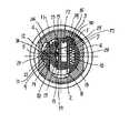
図5に示したように施錠状態においては、可変タンブラ14の錠止突起16はハウジング1の可変タンブラ係入用凹部3に係入しており、バネ18の付勢によってその位置に保持されている。また、サイドバーホルダ19はロータ6のサイドバーホルダ収容孔9内にあり、サイドバー22の先端部23はハウジング1のサイドバー係入用凹部5に係入しており、後端部24がタンブラプレート11の側面端部26に当接していることによって、その位置に保持されている。タンブラプレート11は可変タンブラ14に最も接近した位置にあり、タンブラプレート11の係合部13は可変タンブラ14の鋸歯状被係合部15に係合している。
【0011】
ハウジング1に対するロータ6の回転拘束を解除してロータ6を解錠方向に回転操作するためには、現在のキーコードに対応した個別キーKをロータ6の鍵孔7に挿入する。
この個別キーKの挿入時に、個別キーKの側面エッジ部に加工形成されているキーコード部(いわゆる鍵山部)によって、可変タンブラ14の鍵挿通溝17の内端面が押されるため、可変タンブラ14とタンブラプレート11は一体的に摺動させられ、可変タンブラ14の錠止突起16がハウジング1の可変タンブラ係入用凹部3から脱出する。
【0012】
この段階では、タンブラプレート11のサイドバー係合凹部12は、サイドバー22の後端部24と対面する位置に移動している。そこで、個別キーKによってロータ6を図7において反時計回り方向に回すと、回転当初においてサイドバー22は、先端部23のカム斜面部ないしサイドバー係入用凹部5のカム斜面部の作用によってサイドバー係入用凹部5から押し出され、サイドバー22の後端部24がタンブラプレート11のサイドバー係合凹部12に入り込む。
ロータ6の回転操作は、サイドバーホルダ19がハウジング1のサイドバーホルダ係入用凹部2に対面するキーチェンジ位置の直前位置までなされ、ロータ6は解錠位置に到達する。
【0013】
個別キーKの盗難等によってシリンダ錠のキーコードを変更したいときには、チェンジキーCKをロータ6の鍵孔7に挿入する。
このチェンジキーCKの挿入時にチェンジキーCKのキーコード部によって、可変タンブラ14の鍵挿通溝17の内端面が押されるため、可変タンブラ14とタンブラプレート11は一体的に摺動させられ、可変タンブラ14の錠止突起16がハウジング1の可変タンブラ係入用凹部3から脱出する。
【0014】
この段階では、タンブラプレート11のサイドバー係合凹部12は、サイドバー22の後端部24と対面する位置に移動している。そこで、チェンジキーCKによってロータ6を図5において反時計回り方向に回すと、回転当初においてサイドバー22は、先端部23のカム斜面部ないしサイドバー係入用凹部5のカム斜面部の作用によってサイドバー係入用凹部5から押し出され、サイドバー22の後端部24がタンブラプレート11のサイドバー係合凹部12に入り込む。
このロータ6の回転操作は、サイドバーホルダ19がハウジング1のサイドバーホルダ係入用凹部2に対面するキーチェンジ位置までなされる。
【0015】
このキーチェンジ位置に到達すると、バネ25の付勢によってタンブラプレート11の側面端部26がロータ6のサイドバーホルダ収容孔9に進入させられ、該側面端部26に押動されたサイドバーホルダ19は、その隆起部21をサイドバーホルダ係入用凹部2に係入させる。これによってタンブラプレート11は可変タンブラ14から大きく離反し、タンブラプレート11の係合部13が可変タンブラ14の鋸歯状被係合部15から離脱する。
【0016】
この後、チェンジキーCKをロータ6のタンブラ挿入孔8の長さ方向、すなわちロータ6の横断方向に進退させることによって、可変タンブラ14を押動する。このとき、タンブラプレート11は側面端部26がロータ6のサイドバーホルダ収容孔9に係合しているため固定位置にあり、この固定されたタンブラプレート11に対して可変タンブラ14が移動したため、キーコードが変更されたことになる。
【0017】
この後、鍵孔7からチェンジキーCKを抜き取り、変更後のキーコードを有する別の個別キーKを挿入して逆回転させると、隆起部21の側面がサイドバーホルダ係入用凹部2のエッジ部に押されて、隆起部21がロータ6のサイドバーホルダ収容孔9内に押し戻されるため,タンブラプレート11の側面端部26が該サイドバーホルダ収容孔9から押し出され、タンブラプレート11が可変タンブラ14に接近して、タンブラプレート11の係合部13が可変タンブラ14の鋸歯状被係合部15に係合する。この係合部13と被係合部15の係合位置は、前記可変タンブラ14の押動操作のために変更されている。
【0018】
【発明の実施の形態】
図示の実施例では、図5および図15に示したように可変タンブラ14の他方の側面にはバネ受部27が突設されており、圧縮コイルバネよりなる可変タンブラ付勢用バネ18は、バネ収容孔10の底部と該バネ受部27との間で圧縮されている。図17に示したようにタンブラプレート11の前記他方の側面には、係合部13が両端部に一個ずつ形成されており、図18に示したように該側面中央部にバネ支持部28が背面側にピン状に突設されている。
【0019】
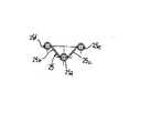
図19に示したようにタンブラプレート付勢用バネ25は捻りコイルバネで構成されており、中央部分のコイル部25aは前記バネ支持部28に嵌合されており、二つの直線部分25b,25cの先端環状曲げ部25d,25eは、図5に示したように可変タンブラ14の前記一方の側面を当接している。二つの環状曲げ部25d,25eの中心を通る直線とコイル部25aの中心間の距離は、タンブラプレート11が可変タンブラ14に接離するのに対応して変動する。
タンブラプレート付勢用バネ25と前記バネ支持部28は、図9、図11、図12に示したようにタンブラ挿入孔8の一側半部の内壁面に形成された逃げ溝29に収容されている。
【0020】
図8、図10に示したように鍵孔7は、ロータ6の中心から一側にずらせて形成されている。図13に示したようにサイドバーホルダ19の前記隆起部21は、低い山形形状に形成されている。図14に示したようにサイドバー22は横断面が略六角形状に形成されており、先端部23と後端部24は山形形状に形成されている。図16に示したように可変タンブラ14の前記バネ受部27の背面にはガイド突起30が突設されており、可変タンブラ14がロータ6の横断方向に摺動するとき、ガイド突起29はバネ収容孔10内を移動する。
ロータ6の後端部には常法に従って回転角度制御板と止め金板が固着される。
【0021】
【発明の効果】
請求項1の発明に係るサイドバー方式の可変コード型シリンダー錠では、キーコードの変更に当たっては、新しい個別キーKをロータ6の鍵孔7に挿入してロータ6を回転させ、サイドバーホルダ19の隆起部21がハウジング1のサイドバーホルダ係入用凹部2に対面したとき、タンブラプレート11の側面端部26をバネ25の付勢によってロータ6のサイドバーホルダ収容孔9に進入させ、これによって隆起部21をサイドバーホルダ係入用凹部2に係入させて、タンブラプレート11の係合部13を可変タンブラ14の鋸歯状被係合部15から離脱させ、この離脱後に可変タンブラ14を所要単位移動させて、最後に係合部13と可変タンブラ14の被係合部15を再係合させるだけでよいので、キーコードの変更操作が容易に行えるとともに、前記した従来の可変コード型シリンダ錠のようにリセットキーやレトラクタといった余分な部品が必要なく、内部機構が簡略化されているため、製作が安価に行える。
ロータ6の前面には通常の鍵孔7しか開口していないため、外観体裁が良く、弄くりに対して強いものとなる。
【0022】
請求項2の発明に係るサイドバー方式の可変コード型シリンダ錠では、タンブラプレート11と可変タンブラ14を、その係合部13を被係合部15に互いに係合させた状態でロータ6のタンブラ挿入孔8に挿入し、可変タンブラ14の錠止突起16をハウジング1の可変タンブラ係入用凹部3に係合させるとともに、サイドバーホルダ19をロータ6のサイドバーホルダ収容孔9に挿入し、サイドバーホルダ19のサイドバー収容孔20に挿入したサイドバー22の先端部23をハウジング1のサイドバー係入用凹部5に係合させ、サイドバー22の基端部24をタンブラプレート11の側面端部26に当接させたので、ハウジング1に対するロータ6の回転拘束が錠止突起16とサイドバー22の2箇所で行われることになり、錠止機能が一段と強化される。
【図面の簡単な説明】
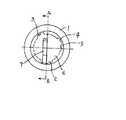
【図1】 本発明の一実施例に係るサイドバー方式の可変コード型シリンダ錠の正面図である。
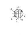
【図2】 図1のシリンダ錠の左側面図である。
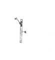
【図3】 図1のシリンダ錠に使用されるキーの右側面図である。
【図4】 図1のA−A線断面図である。
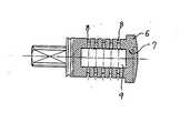
【図5】 図2のB−B線断面図である。
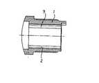
【図6】 図1のシリンダ錠に使用したハウジングの正面図である。
【図7】 図6のC−C線断面図である。
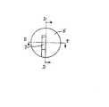
【図8】 図1のシリンダ錠に使用したロータの正面図である。
【図9】 図8のロータの平面図である。
【図10】 図8のD−D線断面図である。
【図11】 図8のE−E線断面図である。
【図12】 図11のF−F線断面図である。
【図13】 図1のシリンダ錠に使用したサイドバーホルダの正面図である。
【図14】 図1のシリンダ錠に使用したサイドバーの右側面図である。
【図15】 図1のシリンダ錠に使用した可変タンブラの拡大正面図である。
【図16】 図15の可変タンブラの左側面図である。
【図17】 図1のシリンダ錠に使用したタンブラプレートの拡大正面図である。
【図18】 図17のタンブラプレートの右側面図である。
【図19】 図1のシリンダ錠に使用したタンブラプレート付勢用バネの拡大正面図である。
【符号の説明】
1 ハウジング
2 サイドバーホルダ係入用凹部
3 可変タンブラ係入用凹部
4 可変タンブラ係入用凹部
5 サイドバー係入用凹部
6 ロータ
7 鍵孔
8 タンブラ挿入孔
9 サイドバーホルダ収容孔
10 バネ収容孔
11 タンブラプレート
12 サイドバー係合凹部
13 係合部
14 可変タンブラ
15 鋸歯状被係合部
16 錠止突起
17 鍵挿通溝
18 可変タンブラ付勢用バネ
19 サイドバーホルダ
20 サイドバー収容孔
21 隆起部
22 サイドバー
23 サイドバーの先端部
24 サイドバーの基端部
25 タンブラプレート付勢用バネ
26 タンブラプレートの側面端部
27 可変タンブラのバネ受部
28 タンブラプレートのバネ支持部
K 個別キー
CK チェンジキー[0001]
BACKGROUND OF THE INVENTION
The present invention relates to a side bar type variable code cylinder lock capable of changing a key code.
[0002]
[Prior art]
Individual key assigned a specific key code is stolen or lost, or when an employee who knows the key code leaves the company Alternatively, there is a risk that the cylinder lock may be illegally unlocked by a person who has an individual key copied based on the key code, and may enter the room or access controlled devices. To remove this risk, the cylinder lock must be replaced with a new one assigned a different key code.
[0003]
However, it is not desirable to replace the cylinder lock mounted on the device or the door because it is very troublesome and wasteful. In order to solve this problem, a side bar type variable code cylinder lock capable of changing a key code is conventionally known (see, for example, Patent Document 1).
[0004]
The cylinder lock is formed in a cylindrical shape, and a housing in which a recess for engaging a side bar and a recess for engaging a retractor are formed on an inner peripheral surface,
A key hole and a reset key insertion hole are formed on the front surface of the housing so as to be rotatable, a side bar accommodation hole is formed on one side of the tumbler insertion hole intersecting the key hole, and a retractor accommodation hole is formed on the other side. A formed rotor;
A tumbler plate that is slidably inserted into the tumbler insertion hole, a side bar engaging recess is formed on one side, and a serrated engaging part is formed on the other side;
A variable tumbler that is loosely fitted into the tumbler insertion hole, has a serrated engaged portion that engages with and disengages from the engaging portion on one surface, and a key insertion groove that communicates with the key hole;
A guide portion and a reset key insertion hole, which are inserted into the retractor receiving hole and slide and guide the variable tumbler in parallel with the tumbler insertion hole, are formed, one end engages with a key inserted into the key insertion groove, and the other A retractor formed with an engagement protrusion engageable with the retractor engaging recess at the end;
Inserted into the sidebar housing hole, the front end is urged in the direction engaging with the sidebar engaging recess, and the rear end engages in the sidebar engaging recess when moved in the opposite direction of urging. Sidebar,
A reset key that pushes the engaging projection of the retractor into the retracting recess for insertion when inserted into the reset key insertion hole and the reset key insertion hole and rotated. It is.
[0005]
In the conventional variable code cylinder lock configured as described above, a reset key insertion hole for driving the retractor is formed in addition to the normal key hole on the front surface of the rotor, so that the appearance is uncomfortable. In addition, the reset key insertion hole becomes a target of tampering, and foreigners may be filled by an unskilled person or the like, which may hinder the key code changing operation. Further, when the key code is changed, a reset key and an individual key that are close to each other are inserted into the rotor. Therefore, their presence interferes with the operation, and workability is not good.
Further, since the internal structure is complicated and the number of parts is large, there is a problem that the manufacturing cannot be performed at a low cost.
[0006]
[Patent Document 1]
1995 Patent Application Publication No. 1977705 [0007]
[Problems to be solved by the invention]
The object of the present invention is that only the normal keyhole is opened on the front surface of the rotor, so that the appearance is good, it is strong against tampering, the key code can be easily changed, and the conventional variable It is an object of the present invention to provide a side-bar type variable code cylinder lock that can be manufactured at low cost because it does not require additional parts such as a reset key and a retractor as in a code cylinder lock and the internal mechanism is simplified.
Another object is to provide a side bar type variable code cylinder lock in which the rotation of the rotor with respect to the housing is firmly restricted at two locations.
[0008]
[Means for Solving the Problems]
Referring to the attached drawings, the sidebar type variable code cylinder lock according to the invention of
A
A
A sawtooth-like engaged
A spring 18 housed in the
The side
It is slidably inserted into the
When the
[0009]
In addition to the structure of the invention of
[0010]
[Effects of the Invention]
As shown in FIG. 5, in the locked state, the
[0011]
In order to release the rotation constraint of the
When the individual key K is inserted, the inner end surface of the
[0012]
At this stage, the side
The
[0013]
When it is desired to change the key code of the cylinder lock due to theft of the individual key K or the like, the change key CK is inserted into the
Since the inner end surface of the
[0014]
At this stage, the side
The rotation operation of the
[0015]
When the key change position is reached, the side end 26 of the
[0016]
Thereafter, the
[0017]
Thereafter, when the change key CK is removed from the
[0018]
DETAILED DESCRIPTION OF THE INVENTION
In the illustrated embodiment, as shown in FIGS. 5 and 15, a
[0019]
As shown in FIG. 19, the tumbler
The tumbler
[0020]
As shown in FIGS. 8 and 10, the
A rotation angle control plate and a clasp plate are fixed to the rear end portion of the
[0021]
【The invention's effect】
In the side bar type variable code cylinder lock according to the first aspect of the invention, when changing the key code, a new individual key K is inserted into the
Since only the
[0022]
In the sidebar type variable cord cylinder lock according to the second aspect of the present invention, the tumbler of the
[Brief description of the drawings]
FIG. 1 is a front view of a side bar type variable code cylinder lock according to an embodiment of the present invention.
FIG. 2 is a left side view of the cylinder lock of FIG.
FIG. 3 is a right side view of a key used for the cylinder lock of FIG. 1;
4 is a cross-sectional view taken along line AA in FIG.
5 is a cross-sectional view taken along line BB in FIG.
6 is a front view of a housing used for the cylinder lock of FIG. 1. FIG.
7 is a cross-sectional view taken along line CC in FIG.
FIG. 8 is a front view of a rotor used in the cylinder lock of FIG. 1;
FIG. 9 is a plan view of the rotor of FIG. 8;
10 is a cross-sectional view taken along the line DD in FIG. 8. FIG.
11 is a cross-sectional view taken along line EE in FIG.
12 is a cross-sectional view taken along line FF in FIG.
13 is a front view of a side bar holder used in the cylinder lock of FIG. 1. FIG.
14 is a right side view of a side bar used in the cylinder lock of FIG. 1. FIG.
15 is an enlarged front view of a variable tumbler used in the cylinder lock of FIG. 1. FIG.
16 is a left side view of the variable tumbler of FIG.
FIG. 17 is an enlarged front view of a tumbler plate used in the cylinder lock of FIG. 1;
FIG. 18 is a right side view of the tumbler plate of FIG.
19 is an enlarged front view of a tumbler plate urging spring used in the cylinder lock of FIG. 1. FIG.
[Explanation of symbols]
DESCRIPTION OF
Claims (2)
Translated fromJapanese前記ハウジング1に回転可能に挿入され、前面に開口する鍵孔7が軸方向に形成され、鍵孔7と交叉するタンブラ挿入孔8の一側にサイドバーホルダ収容孔9が形成され、他側にバネ収容孔10が形成されたロータ6と、
前記タンブラ挿入孔8に摺動可能に挿入され、一方の側面にサイドバー係合凹部12が形成され、他方の側面に係合部13が形成されたタンブラプレート11と、
前記タンブラ挿入孔8に摺動可能に挿入され、一方の面に前記係合部13と係脱する鋸歯状の被係合部15が形成され、中央部分に前記鍵孔7に連通させて鍵挿通溝17が形成された可変タンブラ14と、
前記バネ収容孔10に収容され、可変タンブラ14をハウジング1の内周面に向けて摺動付勢するバネ18と、
前記サイドバーホルダ収容孔9に摺動可能に挿入され、中央部分にサイドバー収容孔20が形成され、ロータ6を回転させたとき、一方の面に形成した隆起部21が前記サイドバーホルダ係入用凹部2に係入するサイドバーホルダ19と、前記サイドバー収容孔20に摺動可能に挿入され、先端部23が前記サイドバー係入用凹部5に係入する方向に付勢され、ロータ6を回転させたとき、前記付勢とは反対方向に移動して基端部24が前記サイドバー係合凹部12に係入するサイドバー22と、
タンブラプレート11をサイドバーホルダ19に向けて付勢し、ロータ6の回転によって前記隆起部21が前記サイドバーホルダ係入用凹部2に対面したとき、タンブラプレート11の側面端部26を前記サイドバーホルダ収容孔9に進入させて、該隆起部21をサイドバーホルダ係入用凹部2に係入させ、タンブラプレート11の前記係合部13を可変タンブラ14の前記被係合部15から離脱させるバネ25とからなるサイドバー方式の可変コード型シリンダ錠。A housing 1 which is formed in a cylindrical shape and has a recess 2 for engaging sidebar holders and a recess 5 for engaging sidebars on an inner peripheral surface;
A key hole 7 that is rotatably inserted into the housing 1 and is opened in the front surface is formed in the axial direction. A side bar holder receiving hole 9 is formed on one side of the tumbler insertion hole 8 that intersects the key hole 7. A rotor 6 having a spring accommodating hole 10 formed therein;
A tumbler plate 11 which is slidably inserted into the tumbler insertion hole 8 and has a sidebar engaging recess 12 formed on one side surface and an engaging portion 13 formed on the other side surface;
A sawtooth-like engaged portion 15 that is slidably inserted into the tumbler insertion hole 8 and is engaged with and disengaged from the engaging portion 13 is formed on one surface, and is connected to the key hole 7 at the center portion to be locked. A variable tumbler 14 in which an insertion groove 17 is formed;
A spring 18 housed in the spring housing hole 10 and slidably biasing the variable tumbler 14 toward the inner peripheral surface of the housing 1;
The side bar holder hole 9 is slidably inserted, a side bar hole 20 is formed at the center, and when the rotor 6 is rotated, a raised portion 21 formed on one surface is associated with the side bar holder. A sidebar holder 19 that engages with the recess 2 for insertion, and is slidably inserted into the sidebar housing hole 20, and the tip 23 is biased in a direction to engage with the recess 5 for engaging the sidebar; When the rotor 6 is rotated, the side bar 22 moves in the direction opposite to the biasing and the base end portion 24 engages with the side bar engaging recess 12;
When the tumbler plate 11 is urged toward the side bar holder 19 and the raised portion 21 faces the side bar holder engaging recess 2 by the rotation of the rotor 6, the side end portion 26 of the tumbler plate 11 is moved to the side bar. The protruding portion 21 is inserted into the bar holder housing hole 9 to engage the side bar holder engaging recess 2, and the engaging portion 13 of the tumbler plate 11 is disengaged from the engaged portion 15 of the variable tumbler 14. A side bar type variable code cylinder lock comprising a spring 25 to be moved.
Priority Applications (9)
| Application Number | Priority Date | Filing Date | Title |
|---|---|---|---|
| JP2002300965AJP3776078B2 (en) | 2002-10-15 | 2002-10-15 | Sidebar type variable code cylinder lock |
| TW92100964ATWI221170B (en) | 2002-10-15 | 2003-01-17 | Side bar type cylinder lock with variable key code |
| KR10-2003-0006517AKR100489987B1 (en) | 2002-10-15 | 2003-02-03 | Side bar type variable code cylinder lock |
| US10/357,915US6755063B2 (en) | 2002-10-15 | 2003-02-04 | Side bar type cylinder lock with variable key code |
| CNB03149451XACN100395423C (en) | 2002-10-15 | 2003-06-16 | Variable coding type cylinder lock with side lever |
| DE2003603099DE60303099T2 (en) | 2002-10-15 | 2003-10-11 | Reversible cylinder lock with side latch |
| AT03256428TATE315149T1 (en) | 2002-10-15 | 2003-10-11 | ADJUSTABLE CYLINDER LOCK WITH SIDE LATCH |
| EP20030256428EP1411192B1 (en) | 2002-10-15 | 2003-10-11 | Side bar type cylinder lock with variable key code |
| HK04106245.6AHK1063497B (en) | 2002-10-15 | 2004-08-20 | Side bar type cylinder lock with variable key code |
Applications Claiming Priority (1)
| Application Number | Priority Date | Filing Date | Title |
|---|---|---|---|
| JP2002300965AJP3776078B2 (en) | 2002-10-15 | 2002-10-15 | Sidebar type variable code cylinder lock |
Publications (2)
| Publication Number | Publication Date |
|---|---|
| JP2004137689A JP2004137689A (en) | 2004-05-13 |
| JP3776078B2true JP3776078B2 (en) | 2006-05-17 |
Family
ID=32040792
Family Applications (1)
| Application Number | Title | Priority Date | Filing Date |
|---|---|---|---|
| JP2002300965AExpired - Fee RelatedJP3776078B2 (en) | 2002-10-15 | 2002-10-15 | Sidebar type variable code cylinder lock |
Country Status (8)
| Country | Link |
|---|---|
| US (1) | US6755063B2 (en) |
| EP (1) | EP1411192B1 (en) |
| JP (1) | JP3776078B2 (en) |
| KR (1) | KR100489987B1 (en) |
| CN (1) | CN100395423C (en) |
| AT (1) | ATE315149T1 (en) |
| DE (1) | DE60303099T2 (en) |
| TW (1) | TWI221170B (en) |
Families Citing this family (41)
| Publication number | Priority date | Publication date | Assignee | Title |
|---|---|---|---|---|
| AUPR838701A0 (en)* | 2001-10-19 | 2001-11-15 | Cylock Pty Ltd | Improved lock |
| US7634930B2 (en) | 2002-01-03 | 2009-12-22 | Strattec Security Corporation | Lock apparatus and method |
| US6862909B2 (en)* | 2002-09-26 | 2005-03-08 | Newfrey Llc | Devices, methods, and systems for keying a lock assembly |
| US6860131B2 (en)* | 2002-09-26 | 2005-03-01 | Newfrey Llc | Rekeying a lock assembly |
| US7114357B2 (en) | 2002-09-26 | 2006-10-03 | Newfrey, Llc | Keying system and method |
| US8347678B2 (en)* | 2002-09-26 | 2013-01-08 | Newfrey, Llc | Rekeyable lock cylinder assembly |
| US6959569B2 (en)* | 2002-09-26 | 2005-11-01 | Newfrey Llc | Re-keyable lock assembly |
| CA2517887C (en)* | 2003-03-04 | 2011-09-13 | Newfrey Llc | Rekeyable lock cylinder assembly with adjustable pin lengths |
| US6951123B2 (en) | 2003-03-05 | 2005-10-04 | Newfrey Llc | Rekeyable lock |
| US6973813B2 (en)* | 2003-12-05 | 2005-12-13 | Newfrey Llc | Re-keyable lock and method |
| US7007528B2 (en) | 2004-04-01 | 2006-03-07 | Newfrey Llc | Re-keyable lock cylinder |
| US20060059965A1 (en)* | 2004-09-17 | 2006-03-23 | Benstead Evan A | Rekeyable lock having 2-piece pin with rotatable member |
| US20060101880A1 (en)* | 2004-11-12 | 2006-05-18 | Ward-Dolkas Paul C | Re-keyable lock cylinder |
| US20060185404A1 (en)* | 2005-02-18 | 2006-08-24 | Hansen Randall C | Codeable padlock |
| CN2818692Y (en) | 2005-09-09 | 2006-09-20 | 玛拉峰电子(苏州)有限公司 | Multifunctional lock |
| US8881567B2 (en)* | 2005-10-21 | 2014-11-11 | Kwikset Corporation | Reset fixture for rekeyable lock assembly |
| JP5008341B2 (en)* | 2006-05-03 | 2012-08-22 | 美和ロック株式会社 | Variable cylinder lock |
| US7392677B1 (en)* | 2007-01-23 | 2008-07-01 | Porter Lock Co., Ltd. | Lock core structure |
| US9719275B1 (en) | 2007-03-12 | 2017-08-01 | Marc W. Tobias | Lock pin rotational position setting key and method of use |
| TW200844314A (en)* | 2007-05-11 | 2008-11-16 | Taiwan Fu Hsing Ind Co Ltd | Lock cylinder fitting to different keys and method for fitting a lock cylinder with different keys |
| TW200900569A (en)* | 2007-06-25 | 2009-01-01 | Taiwan Fu Hsing Ind Co Ltd | A lock core capable of swiftly changing keys and the key changing method thereof |
| US7424815B1 (en)* | 2007-06-12 | 2008-09-16 | Giussani Techniques S.P.A. | Reprogrammable lock |
| CA2691311C (en)* | 2007-06-13 | 2015-11-17 | Schlage Lock Company | Programmable lock cylinder assembly |
| MX2010007820A (en)* | 2008-01-18 | 2010-08-09 | Master Lock Co | Key cylinder lock arrangements. |
| US7980106B2 (en)* | 2008-05-07 | 2011-07-19 | Taiwan Fu Hsing Industrial Co., Ltd. | Rekeyable lock cylinder, plug assembly of the same and method for rekeying the same |
| US8448484B2 (en)* | 2008-05-07 | 2013-05-28 | Taiwan Fu Hsing Industrial Co., Ltd. | Rekeyable lock cylinder |
| TWI372201B (en)* | 2008-05-12 | 2012-09-11 | Taiwan Fu Hsing Ind Co Ltd | Rekeyable lock cylinder, plug assembly of the same and method for rekeying the same |
| AU2009212832A1 (en)* | 2008-08-29 | 2010-03-18 | Tong Lung Metal Industry Co., Ltd. | Re-Keyable Cylinder Lock |
| DE102009030032A1 (en)* | 2009-06-23 | 2010-12-30 | ABUS August Bremicker Söhne KG | Platelet cylinder with lockable platelet tumblers |
| EP2458116B1 (en)* | 2009-07-24 | 2015-12-02 | Pingdingshan Dahan Lock Co., Ltd. | Linkage anti-theft lock head |
| IT1397790B1 (en)* | 2010-01-25 | 2013-01-24 | Rielda Serrature Srl | PROGRAMMABLE CYLINDER LOCK WITH A HIGH NUMBER OF COMBINATIONS. |
| US8099988B1 (en) | 2010-08-09 | 2012-01-24 | Newfrey, Llc | Tool-less rekeyable lock cylinder |
| US8291735B1 (en) | 2011-03-31 | 2012-10-23 | Newfrey, Llc | Rekeyable lock cylinder having rotatable key followers |
| DE102014108355A1 (en)* | 2014-06-13 | 2015-12-17 | ABUS August Bremicker Söhne KG | cylinder lock |
| US9482031B2 (en) | 2014-07-31 | 2016-11-01 | Assa Abloy High Security Group Inc. | Cylinder lock including multiple cooperating sidebars for controlling the lock |
| CN104831997B (en)* | 2015-05-27 | 2017-05-31 | 曹云周 | Anti- reading tooth lockset |
| US10612271B2 (en)* | 2015-06-16 | 2020-04-07 | Spectrum Brands, Inc. | Rekeyable lock cylinder with enhanced torque resistance |
| US11319726B2 (en) | 2018-10-22 | 2022-05-03 | Spectrum Brands, Inc. | Tool-less rekeyable lock cylinder |
| PE20221124A1 (en) | 2019-10-03 | 2022-07-13 | Assa Abloy High Security Group Inc | KEY BLANK WITH MOVABLE ELEMENT, CORRESPONDING KEY AND CORRESPONDING LOCK CAP AND LOCK ASSEMBLY |
| KR102328665B1 (en) | 2020-02-07 | 2021-11-19 | 한울에코텍 주식회사 | Cutting oil tank chip purifier device and control method |
| KR20250084735A (en) | 2023-12-04 | 2025-06-11 | 화천기공 주식회사 | Apparatus for removing cutting fluid using spindle compressed air |
Family Cites Families (16)
| Publication number | Priority date | Publication date | Assignee | Title |
|---|---|---|---|---|
| US3722241A (en)* | 1971-03-03 | 1973-03-27 | Liquidonics Inc | Security cylinder lock |
| US3999413A (en)* | 1975-01-31 | 1976-12-28 | Raymond James W | Lock assembly |
| US3990282A (en)* | 1975-06-24 | 1976-11-09 | Sorum Lorang N | Tumbler type lock |
| FR2367891A1 (en)* | 1976-10-14 | 1978-05-12 | Raymond James | Cylinder lock for vehicles, buildings, furniture - has adjustable locked cams allowing alteration to accept alternative keys while preventing opening with skeleton key |
| US4376382A (en)* | 1980-12-01 | 1983-03-15 | James W. Raymond | Resettable lock assembly |
| US4404824A (en)* | 1981-02-05 | 1983-09-20 | Lori Corporation | Side-bar lock |
| JPS62194374A (en)* | 1986-02-19 | 1987-08-26 | 株式会社クローバー | Lock apparatus |
| US4966021A (en)* | 1988-11-04 | 1990-10-30 | Masco Building Products Corp. | Reprogrammable lock and keys therefor |
| US4942749A (en)* | 1989-06-26 | 1990-07-24 | Jacob Rabinow | Interchangeable key lock with rolling tumblers |
| JP3411358B2 (en)* | 1993-12-28 | 2003-05-26 | 株式会社アルファ | Variable code type cylinder lock |
| DE19544840A1 (en)* | 1995-12-01 | 1997-06-05 | Valeo Deutschland Gmbh & Co | Cylinder lock with turning core containing tumblers in keyhole |
| FR2755173B1 (en)* | 1996-10-31 | 1999-03-05 | Antivols Simplex Sa | SELF-CODE LOCK |
| IT1291177B1 (en)* | 1997-03-10 | 1998-12-29 | Rielda Srl | PROGRAMMABLE CYLINDER LOCK, PROVIDED WITH MASTER KEYS. |
| JP3709146B2 (en)* | 2000-03-09 | 2005-10-19 | 株式会社アルファ | Cylinder lock |
| CN2493701Y (en)* | 2001-07-04 | 2002-05-29 | 陈志和 | Anti-technical opening safety cylinder |
| CA2473531A1 (en)* | 2002-01-03 | 2003-07-17 | Strattec Security Corporation | Vehicular lock apparatus and method |
- 2002
- 2002-10-15JPJP2002300965Apatent/JP3776078B2/ennot_activeExpired - Fee Related
- 2003
- 2003-01-17TWTW92100964Apatent/TWI221170B/ennot_activeIP Right Cessation
- 2003-02-03KRKR10-2003-0006517Apatent/KR100489987B1/ennot_activeExpired - Fee Related
- 2003-02-04USUS10/357,915patent/US6755063B2/ennot_activeExpired - Lifetime
- 2003-06-16CNCNB03149451XApatent/CN100395423C/ennot_activeExpired - Fee Related
- 2003-10-11DEDE2003603099patent/DE60303099T2/ennot_activeExpired - Lifetime
- 2003-10-11EPEP20030256428patent/EP1411192B1/ennot_activeExpired - Lifetime
- 2003-10-11ATAT03256428Tpatent/ATE315149T1/ennot_activeIP Right Cessation
Also Published As
| Publication number | Publication date |
|---|---|
| DE60303099T2 (en) | 2006-08-24 |
| HK1063497A1 (en) | 2004-12-31 |
| KR20040034322A (en) | 2004-04-28 |
| US20040069030A1 (en) | 2004-04-15 |
| EP1411192A1 (en) | 2004-04-21 |
| TW200405918A (en) | 2004-04-16 |
| CN1490487A (en) | 2004-04-21 |
| CN100395423C (en) | 2008-06-18 |
| EP1411192B1 (en) | 2006-01-04 |
| US6755063B2 (en) | 2004-06-29 |
| TWI221170B (en) | 2004-09-21 |
| DE60303099D1 (en) | 2006-03-30 |
| JP2004137689A (en) | 2004-05-13 |
| KR100489987B1 (en) | 2005-05-17 |
| ATE315149T1 (en) | 2006-02-15 |
Similar Documents
| Publication | Publication Date | Title |
|---|---|---|
| JP3776078B2 (en) | Sidebar type variable code cylinder lock | |
| JP4704935B2 (en) | Cylinder lock device and disengagement mechanism | |
| US9003845B2 (en) | Lock apparatus and method | |
| US7131299B1 (en) | Combination lock and padlock combination with opening warning device | |
| US7174756B2 (en) | Padlock | |
| US7370498B1 (en) | Dual-mode padlock | |
| EP1772576B1 (en) | Cylinder lock system and set of keys | |
| JP5385571B2 (en) | Steering lock device | |
| JP5014914B2 (en) | Cylinder lock device | |
| TWI564463B (en) | Lock handle device for door | |
| JP2001500204A (en) | Lever lock device | |
| JP4881843B2 (en) | Steering lock device | |
| JP2881103B2 (en) | Cylinder lock device | |
| US6854307B2 (en) | Lock-picking prevention apparatus | |
| JP7741524B1 (en) | Crescent Tablets | |
| JPH01299968A (en) | Side bar lock device | |
| JP4550637B2 (en) | Thumb turn device | |
| JP2894943B2 (en) | Cylinder lock device | |
| JP2006132107A (en) | Sidebar cylinder lock for replacement of door lock handle device | |
| HK1063497B (en) | Side bar type cylinder lock with variable key code | |
| JP2000087604A (en) | Cylinder lock | |
| JP2002155647A (en) | Cylinder lock | |
| JP3074077U (en) | Double pin tumbler type locking device | |
| JP2553004Y2 (en) | Disk tumbler lock with master device | |
| IT201900001818U1 (en) | LOCKING DEVICE OR PADLOCK FOR FIREARM |
Legal Events
| Date | Code | Title | Description |
|---|---|---|---|
| A977 | Report on retrieval | Free format text:JAPANESE INTERMEDIATE CODE: A971007 Effective date:20051026 | |
| A131 | Notification of reasons for refusal | Free format text:JAPANESE INTERMEDIATE CODE: A131 Effective date:20051216 | |
| A521 | Request for written amendment filed | Free format text:JAPANESE INTERMEDIATE CODE: A523 Effective date:20060110 | |
| TRDD | Decision of grant or rejection written | ||
| A01 | Written decision to grant a patent or to grant a registration (utility model) | Free format text:JAPANESE INTERMEDIATE CODE: A01 Effective date:20060220 | |
| A61 | First payment of annual fees (during grant procedure) | Free format text:JAPANESE INTERMEDIATE CODE: A61 Effective date:20060221 | |
| R150 | Certificate of patent or registration of utility model | Ref document number:3776078 Country of ref document:JP Free format text:JAPANESE INTERMEDIATE CODE: R150 Free format text:JAPANESE INTERMEDIATE CODE: R150 | |
| FPAY | Renewal fee payment (event date is renewal date of database) | Free format text:PAYMENT UNTIL: 20090303 Year of fee payment:3 | |
| FPAY | Renewal fee payment (event date is renewal date of database) | Free format text:PAYMENT UNTIL: 20100303 Year of fee payment:4 | |
| FPAY | Renewal fee payment (event date is renewal date of database) | Free format text:PAYMENT UNTIL: 20110303 Year of fee payment:5 | |
| FPAY | Renewal fee payment (event date is renewal date of database) | Free format text:PAYMENT UNTIL: 20110303 Year of fee payment:5 | |
| FPAY | Renewal fee payment (event date is renewal date of database) | Free format text:PAYMENT UNTIL: 20120303 Year of fee payment:6 | |
| FPAY | Renewal fee payment (event date is renewal date of database) | Free format text:PAYMENT UNTIL: 20130303 Year of fee payment:7 | |
| FPAY | Renewal fee payment (event date is renewal date of database) | Free format text:PAYMENT UNTIL: 20140303 Year of fee payment:8 | |
| LAPS | Cancellation because of no payment of annual fees |