JP3775897B2 - Fertilizer applicator - Google Patents
Fertilizer applicatorDownload PDFInfo
- Publication number
- JP3775897B2 JP3775897B2JP21409097AJP21409097AJP3775897B2JP 3775897 B2JP3775897 B2JP 3775897B2JP 21409097 AJP21409097 AJP 21409097AJP 21409097 AJP21409097 AJP 21409097AJP 3775897 B2JP3775897 B2JP 3775897B2
- Authority
- JP
- Japan
- Prior art keywords
- fertilizer
- fertilization
- nozzle
- power transmission
- transmission unit
- Prior art date
- Legal status (The legal status is an assumption and is not a legal conclusion. Google has not performed a legal analysis and makes no representation as to the accuracy of the status listed.)
- Expired - Fee Related
Links
Images


Landscapes
- Fertilizing (AREA)
Description
Translated fromJapanese【0001】
【発明の属する技術分野】
本発明は、走行機体の両側に設けた上下動する施肥ノズルで、ポンプから圧送される流動性肥料を所定間隔ごとに地中に施肥するようにした施肥機に係るものである。
【0002】
【従来の技術】
一般に畑作用の施肥機には、走行機体の両側に、動力伝導部によつてそれぞれ異なる位相で上下動する施肥ノズルを設け、この施肥ノズルが交互に地中に打込まれたときに、ポンプで圧送された流動性肥料を所定間隔ごとに点状に施肥するようにしたものが知られている。
【0003】
【発明が解決しようとする課題】
ところが、このような従来の施肥機は、上下動する施肥ノズルが機体の重心位置から離れた所に配置されていたので、施肥ノズルが上下動して地中に打込まれるときに、その反力で機体が傾斜して、土の固い圃場では施肥ノズルを深く地中に打込むことができないことがあった。
また、良好な施肥効果を得るため、作物の成育状態あるいは肥料の種類に応じて施肥深さを変える必要があるが、従来は機体の後部にある尾輪を上下動させて施肥深さを変えているので、その都度機体が前後に傾斜して不安定な作業姿勢になってしまい、円滑な施肥作業にも悪影響を及ぼすという問題があった。
【0004】
本発明は、上記の如き実情に鑑み創作されたものであって、その目的とするところは、尾輪を調節することなく施肥ノズルによる地中への施肥深さを容易に調節でき、しかも施肥ノズルが地中へ進入するときの反力により機体が傾斜するのを防止することができる施肥機を提供しようとするものである。
【0005】
【課題を解決するための手段】
上記の課題を解決するため、本発明が講じた技術的手段は、走行車輪を備えた機体フレームの後端部に尾輪を装着し後部上方に操作ハンドルを設けた走行機体の両側に、ポンプから圧送される流動性肥料を上下動する施肥ノズルで地中に施肥する施肥機において、上記施肥ノズルを上下に駆動する動力伝導部を設け、該動力伝導部を覆う伝導ケースに、施肥ノズルおよびポンプを取付けて、動力伝導部と一体的に施肥ノズルおよびポンプを機体に昇降調節可能に取り付けると共に、上記上下動する施肥ノズルを走行車輪の車軸近傍位置で該走行車輪と尾輪の間に配置して、施肥ノズルが地中へ進入するときの反力により機体が傾斜するのを防止することを特徴とし、さらに動力伝導部によって駆動される施肥ノズルが、ガイド板に設けた案内溝に沿って上下動することにより、案内溝の形状を変えて施肥ノズルの打込み角度を調節できるようにしたことを特徴とするものである。
【0006】
【発明の実施の形態】
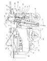
次に本発明の実施の形態を、図面に示された好適な実施例に基づいて詳細に説明する。まず図1〜図4において、1は施肥機の走行機体であって、左右の走行車輪2を備えた機体フレーム3の前部にエンジン4が搭載され、その上方には肥料タンク5、燃料タンク6等が配設されている。7は安全フレーム、8はカバー体、9は肥料受け板である。また機体フレーム3の後端部には尾輪10が装着され、その上方には操作ハンドル11が立設されている。
【0007】
12はエンジン4からの動力伝導部、13は機体の左右両側に設けた施肥ノズルであって、上記動力伝導部12に連動する施肥ノズル13がガイド板14の案内溝15に沿って上下動する。16は上記動力伝導部12を覆う伝導ケースであって、この伝導ケース16に施肥ノズル13が上記動力伝導部12を介して取付けられている。
【0008】
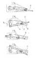
動力伝導部12は、ミッションケース17側の入力軸18と動力伝導部12側の伝導シャフト19とが、ベルト伝動機構20を介して連動連結されており、この伝導シャフト19が伝導ケース16の上部側に設けたクランク軸21に、チェン伝動機構22を介して連結されている。23はクランク軸21に設けたチェンスプロケットである。また、24は上記入力軸18と伝導シャフト19とを連結するリンクアーム、25はベルト伝動機構20のテンションプーリであって、このテンションプーリ25が操作ハンドル11に設けた操作レバー26にワイヤ27で連結されており、操作レバー26の操作により、エンジン4からの動力を断続する。
【0009】
上記クランク軸21の両端には、クランクアーム28の回転軸29がジョイント部30を介して連結され、クランクアーム28に連結した連結ロッド31の先端に前記施肥ノズル13が装着されている。また上記回転軸29にガイド板14が支持されており、ガイド板14の案内溝15に施肥ノズル13の突出杆13aが摺動自在に嵌入して、クランク軸21の回転に伴って図6に示すように施肥ノズル13が案内溝15に沿って上下動するものである。そして上記施肥ノズル13は、機体を支持する走行車輪2の車軸2a近傍に位置するように配置されている。
【0010】
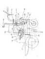
32は伝導ケース16に取付けた上下揺動自在のパイプ、33はパイプ32に挿通された摺動自在のロッドであって、このロッド33の側端がガイド板14に枢着されている。そしてパイプ32とロッド33とを固定する挿通ボルト34の挿通孔33aがロッド33に複数個設けてあって、図2の右半部に示すように、挿通ボルト34の差替えにより、施肥ノズル13による施肥条間隔を調節できるようになっている。なお、この調節は左右の施肥ノズル13について同時に行うものである。
【0011】
35は前記肥料タンク5から肥料繰出しポンプ36を経て連結されたプランジャ型のポンプであって、このポンプ35の肥料送出側がホース37を介して施肥ノズル13の上端に連結されている。また38はクランク軸21に設けたカム、39はカム38の回転により上下揺動するアームであって、このアーム39がポンプ35のプランジャ軸40を押下げて、施肥ノズル13が土中に進入したときに肥料を送出すようになっている。
【0012】
そして上記ポンプ35は動力伝導部12の伝導ケース16の背面に固定されていて、施肥ノズル13とポンプ35とが動力伝導部12と一体的に昇降調節可能となっている。すなわち41は上下方向のネジ棒であって、その下端部がブラケット42を介して機体フレーム3側に支承され、上端にハンドル43が設けられている。44はネジ棒41の中間支持部である。また45は伝導ケース16側に設けた支持ブラケットであって、支持ブラケット45に嵌着した四角状ブロック46に雌ネジ部が設けてあり、この雌ネジ部にネジ棒41が螺入されていて、ハンドル43の操作により、伝導ケース16が一定姿勢を保持したまま上下動して、施肥ノズル13とポンプ35とを伝導ケース16で覆われた動力伝導部12と一体的に昇降調節できるようになっている。
【0013】
また47は上記ネジ棒41のロックプレートであって、レバー48,49の締付け操作によりロックプレート47がネジ棒41を昇降調節位置に固定するものである。50は操作ハンドル11に設けたエンジンスイッチ、51は尾輪10の高さを固定するストッパ、また52は肥料の戻りホース、53は機体のバランスウエイトである。なお、安全フレーム7は、図5に示すようにエンジンフレーム54から突出した支持パイプ55に取付け、この安全フレーム7で肥料タンク5、燃料タンク6、カバー体8等を支持することにより、支持構造が簡素化されている。
【0014】
上記のように構成したので、施肥作業を行うにあたり、走行車輪2を駆動しながらオペレータが操作ハンドル11を把持して畝間を走行すれば、クランク軸21の回転に伴って施肥ノズル13が上下動する。そして施肥ノズル13が地中に進入するときに揺動するアーム39がポンプ35のプランジャ軸40押下げて肥料を送出し、畝に沿って所定間隔ごとに点状に土中施肥してゆく。そして作物の成育状態あるいは肥料の種類に応じて施肥深さを変えるときには、ハンドル43を操作するのみで、施肥ノズル13とポンプ35とを伝導ケース16で覆われた動力伝導部12とともに一体的に昇降調節できるので、従来のように尾輪の調節によって機体を傾斜させることはなく、機体を安定した作業姿勢に保持したまま、適正な施肥深さに調節することができ、また上下方向のネジ棒41に沿って調節範囲を広くすることができる。
【0015】
そして、上下動する施肥ノズル13は、走行車輪2の車軸2a近傍に位置しており、しかも施肥ノズル13の上部に動力伝導部12が位置するので、施肥ノズル13を略機体重量による荷重で地中に打込むことができ、その打込み反力で機体が傾斜するようなことはない。
【0016】
またガイド板14の案内溝15に沿って上下動する施肥ノズル13は、案内溝15の形状をかえれば、上下動軌跡を変えることができるので、走行速度等の作業条件に応じて施肥ノズル13の地中への打込み角度を自由に調整することができる。なお挿通ボルト34の差替えにより、施肥ノズル13の施肥条間隔も簡単に調節することができる。
【0017】
【発明の効果】
これを要するに本発明は、走行車輪を備えた機体フレームの後端部に尾輪を装着し後部上方に操作ハンドルを設けた走行機体の両側に、ポンプから圧送される流動性肥料を上下動する施肥ノズルで地中に施肥する施肥機において、上記施肥ノズルを上下に駆動する動力伝導部を設け、該動力伝導部を覆う伝導ケースに、施肥ノズルおよびポンプを取付けて、動力伝導部と一体的に施肥ノズルおよびポンプを機体に昇降調節可能に取り付けると共に、上記上下動する施肥ノズルを走行車輪の車軸近傍位置で該走行車輪と尾輪の間に配置し、また、動力伝導部によって駆動される施肥ノズルが、ガイド板に設けた案内溝に沿って上下動することから、施肥ノズルおよびポンプを動力伝導部と一体的に昇降調節できるので、施肥ノズルによる地中への施肥深さを容易に調節することができる。
【0018】
そして走行車輪の車軸近傍位置に配置した施肥ノズルは、機体重心の近くで地中に進入するので、略機体重量による荷重のみで容易に地中に進入させることができ、このため施肥ノズルの反力により機体が傾斜するのを防止することができる。
また、施肥ノズルが、ガイド板に設けた案内溝に沿って上下動するものでは、案内溝の形状を変えれば、施肥ノズルの地中への打込み角度を作業条件に応じて自由に調節できるので、円滑に施肥作業を行うことができるものである。
【図面の簡単な説明】
【図1】施肥機の全体側面図である。
【図2】同上背面図である。
【図3】動力伝導部の側面図である。
【図4】同上平面展開図である。
【図5】安全フレームの平面図である。
【図6】施肥ノズルの作動説明図である。
【符号の説明】
1 走行機体
2 走行車輪
2a 車軸
12 動力伝導部
13 施肥ノズル
14 ガイド板
15 案内溝
16 伝導ケース
35 ポンプ[0001]
BACKGROUND OF THE INVENTION
The present invention relates to a fertilizer applicator that is provided with fertilizer nozzles that move up and down on both sides of a traveling machine body so that fluid fertilizer pumped from a pump is fertilized into the ground at predetermined intervals.
[0002]
[Prior art]
Generally, fertilizers for field action are provided with fertilizer nozzles that move up and down at different phases by the power transmission parts on both sides of the traveling machine body, and when these fertilizer nozzles are alternately driven into the ground, the pump There is known a fluid fertilizer that has been fed in a fertilizer at a predetermined interval.
[0003]
[Problems to be solved by the invention]
However, in such a conventional fertilizer application machine, the fertilizer nozzle that moves up and down is arranged away from the center of gravity of the machine body, so when the fertilizer nozzle moves up and down and is driven into the ground, The aircraft tilted by force, and sometimes the fertilizer nozzle could not be driven deep into the ground in fields with hard soil.
In addition, in order to obtain a good fertilization effect, it is necessary to change the fertilization depth according to the growth state of the crop or the type of fertilizer, but conventionally, the tailing wheel at the rear of the aircraft is moved up and down to change the fertilization depth. As a result, the airframe tilts back and forth each time, resulting in an unstable working posture, which has a problem of adversely affecting smooth fertilization work.
[0004]
The present invention was created in view of the above circumstances, and the object of the present invention is to easily adjust the fertilization depth of the fertilizer nozzle into the ground without adjusting the tail wheel, and to apply fertilizer. It is an object of the present invention to provide a fertilizer applicator capable of preventing the airframe from being inclined by a reaction force when a nozzle enters the ground.
[0005]
[Means for Solving the Problems]
In order to solve the above-mentioned problems, the technical means taken by the present invention is that pumpsare installed on both sides ofa traveling machine bodyhaving a tail wheel attached to the rear end of the machine frame equipped with traveling wheels and provided with an operation handle above the rear part. In a fertilizer applying fertilizer into the ground with a fertilizer nozzle that moves fluid fertilizer pumped up and down, a power transmission unit that drives the fertilization nozzle up and down is provided, and in a conduction case that covers the power transmission unit, a fertilizer nozzle and Install the pump, power transmission unit integrally with fertilization nozzles and pumps the lifting adjustablymounted Rutotomonito the body,between the running wheels and tail wheel at axle vicinity of the traveling wheel fertilization nozzle to the aforementioned vertical movement It is arranged to prevent the airframe from tilting due to the reaction force when the fertilizer nozzle enters the ground, and the fertilizer nozzle driven by the power transmission unit is provided on the guide plate By moving up and down along, it is characterized in that to be able to adjust the angle of implant of fertilization nozzles by changing the shape of the guide groove.
[0006]
DETAILED DESCRIPTION OF THE INVENTION
Next, embodiments of the present invention will be described in detail based on preferred examples shown in the drawings. First, in FIGS. 1 to 4, reference numeral 1 denotes a traveling body of a fertilizer applicator, in which an engine 4 is mounted on a front portion of a body frame 3 having left and right traveling
[0007]
12 is a power transmission portion from the
[0008]
In the
[0009]
A rotating
[0010]
[0011]
[0012]
The
[0013]
Reference numeral 47 denotes a lock plate for the screw rod 41. The lock plate 47 fixes the screw rod 41 at the elevation adjustment position by tightening the
[0014]
Since it comprised as mentioned above, if an operator grips the operation handle |
[0015]
The fertilizing
[0016]
Further, since the
[0017]
【The invention's effect】
In short, the present invention moves the fluid fertilizer pumped from the pump up and down on both sides ofthe traveling machine body,which is equipped with a tail wheel at the rear end of the machine frame equipped with traveling wheels and provided with an operating handle above the rear part. In a fertilizer applicator that applies fertilizer into the ground with a fertilizer nozzle, a power transmission unit that drives the fertilization nozzle up and down is provided, and a fertilization nozzle and a pump are attached to a conduction case that covers the power transmission unit, and integrated with the power transmission unit fertilizing nozzle and pump disposedbetween the running wheel and the tail wheel lift adjustablymounted Rutotomonito the body, the fertilization nozzle the vertical movement at the axle vicinity of the running wheels, also driven by the power transmission unit Since the fertilizer nozzle moves up and down along the guide groove provided on the guide plate, the fertilizer nozzle and pump can be adjusted up and down integrally with the power transmission part, so Fertilization depth can be easily adjusted.
[0018]
Since the fertilizer nozzle placed near the axle of the traveling wheel enters the ground near the center of gravity of the aircraft, it can easily enter the ground only with a load due to the weight of the aircraft. It is possible to prevent the aircraft from being tilted by force.
Also, if the fertilizer nozzle moves up and down along the guide groove provided on the guide plate, the angle of driving the fertilizer nozzle into the ground can be adjusted freely according to the working conditions by changing the shape of the guide groove The fertilization work can be performed smoothly.
[Brief description of the drawings]
FIG. 1 is an overall side view of a fertilizer applicator.
FIG. 2 is a rear view of the same.
FIG. 3 is a side view of a power transmission unit.
FIG. 4 is a plan development view of the same.
FIG. 5 is a plan view of a safety frame.
FIG. 6 is an operation explanatory view of a fertilizer application nozzle.
[Explanation of symbols]
DESCRIPTION OF SYMBOLS 1 Traveling
Claims (2)
Translated fromJapanesePriority Applications (1)
| Application Number | Priority Date | Filing Date | Title |
|---|---|---|---|
| JP21409097AJP3775897B2 (en) | 1997-07-23 | 1997-07-23 | Fertilizer applicator |
Applications Claiming Priority (1)
| Application Number | Priority Date | Filing Date | Title |
|---|---|---|---|
| JP21409097AJP3775897B2 (en) | 1997-07-23 | 1997-07-23 | Fertilizer applicator |
Publications (2)
| Publication Number | Publication Date |
|---|---|
| JPH1132535A JPH1132535A (en) | 1999-02-09 |
| JP3775897B2true JP3775897B2 (en) | 2006-05-17 |
Family
ID=16650071
Family Applications (1)
| Application Number | Title | Priority Date | Filing Date |
|---|---|---|---|
| JP21409097AExpired - Fee RelatedJP3775897B2 (en) | 1997-07-23 | 1997-07-23 | Fertilizer applicator |
Country Status (1)
| Country | Link |
|---|---|
| JP (1) | JP3775897B2 (en) |
Families Citing this family (3)
| Publication number | Priority date | Publication date | Assignee | Title |
|---|---|---|---|---|
| US9689615B2 (en) | 2012-08-21 | 2017-06-27 | Uop Llc | Steady state high temperature reactor |
| US9656229B2 (en) | 2012-08-21 | 2017-05-23 | Uop Llc | Methane conversion apparatus and process using a supersonic flow reactor |
| CN115380807A (en)* | 2022-09-05 | 2022-11-25 | 无棣县优程为农服务有限公司 | Cotton multi-layer fertilizer applicator |
- 1997
- 1997-07-23JPJP21409097Apatent/JP3775897B2/ennot_activeExpired - Fee Related
Also Published As
| Publication number | Publication date |
|---|---|
| JPH1132535A (en) | 1999-02-09 |
Similar Documents
| Publication | Publication Date | Title |
|---|---|---|
| CA1243881A (en) | Drive mechanism for turf aerating apparatus | |
| CA1267561A (en) | Turf aerating apparatus | |
| JP3775897B2 (en) | Fertilizer applicator | |
| JP3573611B2 (en) | Fertilizer application nozzle device | |
| US4155408A (en) | Engine driven garden plow for breaking up soil with levers for adjusting plow thereof | |
| JP3377445B2 (en) | Rice transplanter seedling mount | |
| JP3971230B2 (en) | Rice transplanter fertilizer | |
| JPH081603Y2 (en) | Management work vehicle | |
| JPS59143520A (en) | Fertilizer application device in rice transplanter | |
| JP3519915B2 (en) | Fender structure of riding rice transplanter | |
| JP2843423B2 (en) | Fertilizer | |
| JPH0218989Y2 (en) | ||
| JP2536464B2 (en) | Riding rice transplanter with fertilizer application | |
| JP2522558Y2 (en) | Fertilizer application equipment in rice transplanters | |
| JPS6224421Y2 (en) | ||
| JPH0537014U (en) | Stopper body of rolling device in paddy working machine | |
| JPH0427295Y2 (en) | ||
| JPH0733613Y2 (en) | Fertilizer working machine | |
| JP3163080B2 (en) | Planting part transmission structure in riding rice transplanter | |
| JPH05260813A (en) | Rice transplanter with manuring device | |
| JP2001008508A (en) | Potato transplanter | |
| JPH11206212A (en) | Transmission device for fertilizing machine | |
| JP2520993Y2 (en) | Liquid spraying device | |
| JP2004222584A (en) | Fertilizer applicator | |
| JP2508787B2 (en) | Riding type farm work machine |
Legal Events
| Date | Code | Title | Description |
|---|---|---|---|
| A621 | Written request for application examination | Free format text:JAPANESE INTERMEDIATE CODE: A621 Effective date:20040430 | |
| RD04 | Notification of resignation of power of attorney | Free format text:JAPANESE INTERMEDIATE CODE: A7424 Effective date:20040528 | |
| A977 | Report on retrieval | Free format text:JAPANESE INTERMEDIATE CODE: A971007 Effective date:20050908 | |
| A131 | Notification of reasons for refusal | Free format text:JAPANESE INTERMEDIATE CODE: A131 Effective date:20050920 | |
| A521 | Written amendment | Free format text:JAPANESE INTERMEDIATE CODE: A523 Effective date:20051116 | |
| TRDD | Decision of grant or rejection written | ||
| A01 | Written decision to grant a patent or to grant a registration (utility model) | Free format text:JAPANESE INTERMEDIATE CODE: A01 Effective date:20060214 | |
| A61 | First payment of annual fees (during grant procedure) | Free format text:JAPANESE INTERMEDIATE CODE: A61 Effective date:20060221 | |
| FPAY | Renewal fee payment (event date is renewal date of database) | Free format text:PAYMENT UNTIL: 20100303 Year of fee payment:4 | |
| FPAY | Renewal fee payment (event date is renewal date of database) | Free format text:PAYMENT UNTIL: 20110303 Year of fee payment:5 | |
| FPAY | Renewal fee payment (event date is renewal date of database) | Free format text:PAYMENT UNTIL: 20120303 Year of fee payment:6 | |
| FPAY | Renewal fee payment (event date is renewal date of database) | Free format text:PAYMENT UNTIL: 20130303 Year of fee payment:7 | |
| FPAY | Renewal fee payment (event date is renewal date of database) | Free format text:PAYMENT UNTIL: 20140303 Year of fee payment:8 | |
| S533 | Written request for registration of change of name | Free format text:JAPANESE INTERMEDIATE CODE: R313533 | |
| R350 | Written notification of registration of transfer | Free format text:JAPANESE INTERMEDIATE CODE: R350 | |
| LAPS | Cancellation because of no payment of annual fees |