JP3775319B2 - Music waveform time stretching apparatus and method - Google Patents
Music waveform time stretching apparatus and methodDownload PDFInfo
- Publication number
- JP3775319B2 JP3775319B2JP2002078271AJP2002078271AJP3775319B2JP 3775319 B2JP3775319 B2JP 3775319B2JP 2002078271 AJP2002078271 AJP 2002078271AJP 2002078271 AJP2002078271 AJP 2002078271AJP 3775319 B2JP3775319 B2JP 3775319B2
- Authority
- JP
- Japan
- Prior art keywords
- waveform
- time
- start timing
- beat
- sine wave
- Prior art date
- Legal status (The legal status is an assumption and is not a legal conclusion. Google has not performed a legal analysis and makes no representation as to the accuracy of the status listed.)
- Expired - Fee Related
Links
- 238000000034methodMethods0.000titleclaimsdescription26
- 238000001228spectrumMethods0.000claimsdescription18
- 230000008707rearrangementEffects0.000claimsdescription17
- 238000010183spectrum analysisMethods0.000claimsdescription17
- 238000000605extractionMethods0.000claimsdescription15
- 230000015572biosynthetic processEffects0.000claimsdescription12
- 238000003786synthesis reactionMethods0.000claimsdescription12
- 239000002131composite materialSubstances0.000claimsdescription7
- 230000003595spectral effectEffects0.000claims2
- 238000010586diagramMethods0.000description17
- 230000033764rhythmic processEffects0.000description7
- 230000002194synthesizing effectEffects0.000description7
- 230000001755vocal effectEffects0.000description7
- 230000006835compressionEffects0.000description5
- 238000007906compressionMethods0.000description5
- 230000000694effectsEffects0.000description4
- 230000002238attenuated effectEffects0.000description3
- 238000005070samplingMethods0.000description3
- 238000004364calculation methodMethods0.000description2
- 238000004140cleaningMethods0.000description2
- 230000006870functionEffects0.000description2
- 239000000203mixtureSubstances0.000description2
- 230000006837decompressionEffects0.000description1
- 238000001514detection methodMethods0.000description1
- 239000000284extractSubstances0.000description1
- 230000001020rhythmical effectEffects0.000description1
- 238000004904shorteningMethods0.000description1
Images


Landscapes
- Electrophonic Musical Instruments (AREA)
Description
Translated fromJapanese【0001】
【発明の属する技術分野】
本発明は、演奏時間の圧縮伸張を、音楽波形の音色やピッチを変化させることなく行う、音楽波形のタイムストレッチに関するものである。
例えば、コマーシャル用に演奏された所定の音楽波形を、その音色やピッチを変化させることなく、その演奏時間を任意の時間に正確に合わせ込む必要がある場合に用いることができる。
あるいは、演奏テンポの変更を、音楽波形の音色やピッチを変化させることなく自由に行いたい場合に用いることができる。
【0002】
【従来の技術】
従来、音楽波形の再生時間だけを、音色やピッチをほぼそのままに、自由に変化させる技術、言い替えれば、テンポのみを変化させる技術として、音楽波形のタイムストレッチ技術が知られている。
従来のタイムストレッチ技術としては、ビート(拍子)抽出型、ボコーダ型が知られている。
【0003】
ビート抽出型のタイムストレッチは、音楽波形の急峻な立ち上がりを検出して音符に分割し、各音符の時間間隔を縮めたり伸ばしたりすることによって、音楽波形全体の再生時間を変化させるものである。周波数スペクトルの時間変化が大きいリズム系、パーカッシブな音楽のタイムストレッチに関しては、ある程度の品質が得られる。
しかし、この方法は、原音楽波形そのものを音符単位で時間移動しているだけであるので、定常波形部分は途中で打ち切られたり、定常波形部分に無音区間が埋め込まれたりするので、ボーカルやアンサンブル系の音楽に不向きである。
【0004】
一方、ボコーダ型のタイムストレッチは、音楽波形を周波数分析して得られた主要な周波数成分について、時間軸を縮めたり伸ばしたりした後に、各周波数成分を加算するというものである。ボーカルやアンサンブル系の音楽に関しては、ある程度の品質が得られる。
しかし、全ての周波数成分を全て処理することは困難であるので、多数の倍音周波数成分や、非倍音周波数成分などが含まれたリズム系の音楽には不向きである。
ところが、通常の音楽波形は、リズムやメロディ、さらには、ボーカルも含まれる場合もあるので、いずれを用いてタイムストレッチしても、思うような品質を得ることができないという問題があった。
同様に、ソロ楽器であっても、ピアノのように、アタック音(ハンマー音など)の後に緩やかな減衰振動を伴うような楽音の演奏波形を高品位にタイムストレッチすることは困難であった。
【0005】
【発明が解決しようとする課題】
本発明は、上述した問題点を解決するためになされたもので、音楽波形の高品位な時間軸圧縮伸張を実現できる音楽波形のタイムストレッチ装置および音楽波形のタイムストレッチ方法を提供することを目的とするものである。
【0006】
【課題を解決するための手段】
本発明は、請求項1に記載の発明においては、音楽波形のタイムストレッチ装置において、原音楽波形に対して所定の時間間隔で短時間スペクトル分析が行われて得られた、スペクトルのピーク点データと、該スペクトルのピーク点データからは正弦波合成できない残差波形とを入力する短時間スペクトル分析結果の入力手段と、前記残差波形の振幅に基づいて第1のビート開始タイミングを抽出するビート開始タイミング抽出手段と、前記第1のビート開始タイミングを、所定のタイムストレッチ率に応じて再配置して第2のビート開始タイミングを決定するとともに、前記残差波形を、前記第1のビート開始タイミング毎に分割し、分割された前記残差波形を前記第2のビート開始タイミングの位置に再配置する残差波形のタイムストレッチ手段と、前記スペクトルのピーク点データを前記第1のビート開始タイミング毎に分割し、分割された各区間の前記スペクトルのピーク点データを、前記第2のビート開始タイミングで区切られた期間にわたって再配置した上で正弦波合成する正弦波合成波形のタイムストレッチ手段と、前記残差波形のタイムストレッチ手段の出力および前記正弦波合成波形のタイムストレッチ手段の出力とを加算する加算手段を有するものである。
したがって、音楽波形の2種類の音楽成分別にその音楽成分に適した時間軸圧縮伸張を行った上で、両者を同期して合成することが可能となり、音楽波形を高品位に時間軸圧縮伸張することができる。
【0007】
請求項2に記載の発明においては、音楽波形のタイムストレッチ装置において実行されるタイムストレッチ方法であって、原音楽波形に対して所定の時間間隔で短時間スペクトル分析が行われて得られた、スペクトルのピーク点データと、該スペクトルのピーク点データからは正弦波合成できない残差波形とを入力する短時間スペクトル分析結果の入力ステップと、該短時間スペクトル分析結果の入力ステップにより入力された残差波形の振幅に基づいて第1のビート開始タイミングを抽出するビート開始タイミング抽出ステップと、前記第1のビート開始タイミングを、所定のタイムストレッチ率に応じて再配置して第2のビート開始タイミングを決定するとともに、前記短時間スペクトル分析結果の入力ステップにより入力された残差波形を、前記第1のビート開始タイミング毎に分割し、分割された前記残差波形を前記第2のビート開始タイミングの位置に再配置する残差波形のタイムストレッチステップと、前記短時間スペクトル分析結果の入力ステップにより入力されたスペクトルのピーク点データを前記第1のビート開始タイミング毎に分割し、分割された各区間の前記スペクトルのピーク点データを、前記第2のビート開始タイミングで区切られた期間にわたって再配置した上で正弦波合成する正弦波合成波形のタイムストレッチステップと、前記残差波形のタイムストレッチステップの出力および前記正弦波合成波形のタイムストレッチステップの出力とを加算する加算ステップを有するものである。
したがって、請求項1に記載の発明と同様の作用を奏する。CPUやDSPを用いて実現することができる。
【0008】
【発明の実施の形態】
本発明は、原音楽波形を、上述したビート法に適した音楽成分および上述したボコーダ法に適した音楽成分に分離し、後で加算可能な形で個別にタイムストレッチ(時間軸圧縮伸張)を行うものである。
具体的には、音楽波形の分析合成ツールを用いて行う。例えば、音楽波形に含まれる基音周波数成分、倍音周波数成分、非倍音周波数成分に対応する線スペクトル成分を抽出する。
通常、分析窓(ウインドウ)を用いたフーリエ変換(短時間フーリエ変換、STFFT:Short-Time Fast Fourier Transform)による短時間スペクトル分析を行う。この短時間スペクトル分析自体は、特開2000−10567号公報等で知られている。
【0009】
音楽波形の分析としては、音楽波形をサンプリングし、1フレーム(分析フレーム)サイズの複数サンプルポイントに対して窓関数を掛け算し、その出力レベルから周波数成分を分析する。この1回の処理を1フレームの処理単位として、上述した分析窓を1ホップサイズだけ移動させて、順次、次のフレームに対して同様の処理を行う。
1つのフレームと次のフレームとは、ホップサイズ分だけ時間がずれている。ホップサイズは、サンプルポイント数で表現される。これを時間に換算したものをフレームタイムと定義すると、(フレームタイム)=(ホップサイズ)/(サンプリング周波数)である。通常、ホップサイズは、ウインドウサイズよりも小さくするので、フレーム期間および分析窓は複数サンプルポイントにわたってオーバラップすることになる。
【0010】
各フレームにおける分析結果から、周波数成分のピーク点を順次検出する。
ここで、各周波数成分のピーク点は、周波数データ(fx)、位相データ(各周波数成分の基準位相2πfxtに対する位相差px)、および振幅データ、という3つのデータを有している。
各フレーム単位で、各周波数成分の振幅データからピークを成す周波数位置を検出することにより、ピーク点を抽出する。ピークを成すものを全て検出してもよいが、処理量を減らすため、ピークの振幅が所定の閾値以下のものを切り捨ててもよい。あらかじめ複数のフレームにわたってピーク点の軌跡を追跡することにより、所定のフレーム数以上継続するピーク点のみを出力するなど、これらのクリーニング処理をしてピーク点を出力してもよい。
【0011】
次に、各ピーク点軌跡に対応する正弦波信号の周波数、位相、振幅を、各フレーム単位で得られたスペクトルのピーク点データに基づいて設定し、複数フレームにわたって、この正弦波信号の周波数、位相、振幅を制御する。得られた複数の正弦波信号を、複数フレームにわたって加算合成することにより、正弦波合成された合成音楽波形が生成される。
原音楽波形からこの合成音楽波形を減算すれば、ピーク点データSTFDATAからは正弦波合成できない音楽波形が出力される。この波形は、残差波形と呼ばれている。
場合によって、最初のスペクトル分析で得られた残差波形を更にスペクトル分析して、正弦波合成波形の精度を上げることが行われる。この場合でも、前回よりも小さくなるが残差波形が残る。
【0012】
図1は、本発明のタイムストレッチ装置のブロック構成図である。
図中、1はSTFFT分析部、2はビート抽出部、3は正弦波合成できない波形のタイムストレッチ部、4は正弦波合成できる波形のタイムストレッチ部、5は加算器である。
STFFT(Short-Time Fast Fourier Transform)分析部1は、対象とする原音楽波形を短時間高速フーリエ変換し、ピーク点データSTFDATAと、ピーク点データに基づいて正弦波合成できなかった波形(Xesidual:残差波形)とを出力する。
【0013】
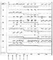
図2は、ピアノ演奏波形の波形図である。
図2(a)は原音楽波形、図2(b)は残差波形、図2(c)は残差波形のエンベロープ波形を示す波形図である。
各波形図において横軸は時間、縦軸は波形振幅である。各波形図の時間軸は同じになるように合わせているが、波形振幅のスケールは異なっている。
ビートに対してA,B,C,……の符号を付している。
図3は、ピアノ演奏波形をSTFFT分析したときのピーク点データを示す分析図である。横軸はフレーム番号で表した時間、縦軸は周波数である。原音楽波形が、図2(a)に示した音楽波形の場合のピーク点データSTFDATAを、クリーニング処理したものを示す。
【0014】
図3に示すように、各フレームにおいて、ピーク点が複数個検出される。これらのピーク点は、元のサンプリング波形の基音周波数成分、倍音周波数成分、非倍音成分、ノイズ成分等に対応して検出されるようになる。このため、ピーク点は、フレーム毎に離散した点状であるが、フレーム間で短い連続性を有するもの、フレーム間で長い連続性を有するものなど、種々のピーク点の態様がある。
図3では、ある程度の長さの軌跡をなすピーク点について図示している。
また、残差波形Xesidualは図2(b)のようになる。図2(a)に示したピアノの演奏波形であれば、残差波形Xesidualは、アタックのカチッという打弦音である。したがって、アタックタイミング毎に大きな残差波形Xesidualがある。残差波形Xesidualは、リズム+ボーカルの音楽波形であれば、パーカッシブなリズム音、ボーカルの子音、あるいは、ノイズである。
【0015】
図1に示したビート抽出部2は、残差波形から、原音楽波形のビート(拍子)開始タイミングを抽出する。抽出方法は任意でよいが、以下の例では、エンベロープレベルを検出する方法を示す。
まず、図2(c)のような残差波形のエンベロープを計算する。次に、所定のスレッショルドレベルVthと残差波形のエンベロープとの交点を、波形のアタックポイントとし、そこから時間の過去側へ数msの所定時間Δだけ戻した時点a,b,c,……をビートの切れ目(ビート開始タイミング)とする。
【0016】
スレッショルドレベルVthは、所定値か、残差波形のエンベロープのピーク値の所定数分の1の値とすればよい。音楽波形の立上りはノイズ成分が多く不確定であるので、スレッショルドレベルVthをあまり下げることはできない。これに対し、上述した方法では、スレッショルドレベルVthをあまり下げなくてもビートの切れ目を精度良く検出できる。
ビート開始タイミングの抽出は、この他にも、残差波形をノイズ除去フィルタを通してからその振幅レベルをゼロクロス検出する方法などがある。
【0017】
正弦波合成できない波形のタイムストレッチ部3は、ビート抽出部2から出力される、原音楽波形(正確には、その残差波形)のビート開始タイミングの情報を入力する。
このビート開始タイミングの間隔(ビート周期)を、ユーザ操作により設定される任意のタイムストレッチ率に比例して変化させることにより、タイムストレッチ後の新たなビート周期を決定し、ビート開始タイミングを再配置する。
同時に、残差波形を、原音楽波形のビート抽出部2から出力されるビート開始タイミング毎に分割し、分割された残差波形の先頭が、再配置後のビート開始タイミングの位置になるように、分割された残差波形を再配置することにより、タイムストレッチされた残差波形を生成する。
なおタイムストレッチ率は、ビート開始タイミングの間隔を単位として、時間的に変化させることができる。
【0018】
図4は、正弦波合成できない残差波形のタイムストレッチ処理の説明図である。
図4(a)はタイムストレッチ前の残差波形、図4(b)はタイムストレッチ後の残差波形である。横軸は時間、縦軸は振幅である。
図示の例では、説明を簡単化するために、タイムストレッチ率を一定値「2倍」とした具体例について説明する。
まず、原音楽波形のビート開始タイミングa,b,c,d,e,f,…を、2倍のタイムストレッチ率に応じて再配置して、再配置後のビート開始タイミングa’,b’,c’,d’,e’,f’,…を決定する。
一方、残差波形Xesidualを、元のビート開始タイミングごとに、ビート周期Ta,Tb,Tc,……の期間に分割し、分割された残差波形を再配置後のビート開始タイミングa,b,c,d,e,f,…で区切られた、ビート周期Ta',Tb',Tc',……の区間の先頭、すなわち、再配置後のビート開始タイミングの位置に再配置する。
【0019】
単に再配置しただけでは、再配置後の隣接する残差波形の間がゼロレベルのままである。ゼロレベルのままでもよいが、この残差波形の間の区間を何らかの方法で埋めることもできる。
埋める方法は何でもよい。例えば、ビート抽出部2において作成されたエンベロープの情報から、あるスレッショルドレベル(上述したスレッショルドレベルVthとは独立して決められる)以下に減衰した区間では、ホワイトノイズ等のノイズ信号にクロスフェードし、かつ、滑らかに減衰させればよい。
あるいは、上述したスレッショルドレベル以下に減衰した区間を繰り返しループさせ、かつ、滑らかに減衰させればよい。
逆に、タイムストレッチ率を1未満にしたときに、そのままでは、切り出された残差波形が重なることになってしまう。この場合は、ビートの切れ目で、前の残差波形を切り捨ててから、後の残差波形につなげばよい。もともと残差波形の振幅レベルは小さいので切り捨ての影響は小さい。
【0020】
一方、正弦波合成できる波形のタイムストレッチ部4は、STFFT分析部1から出力されたピーク点データを、ビート抽出部2から出力される原音楽波形のビート開始タイミングの情報を用いて、残差波形のビート開始タイミング毎に分割する。次に、正弦波合成できない波形のタイムストレッチ部3から出力される再配置後のビート開始タイミングの情報を用いて、分割された各期間のスペクトルのピーク点データを、再配置後のビート開始タイミングで区切られた期間にわたって再配置した上で正弦波合成することにより、再配置された正弦波合成波形を出力する。
【0021】
なお、再配置は、タイムストレッチ率に比例したものであるから、残差波形のビート開始タイミング毎に分割することなく、対象とする原音楽波形全体を一括して再配置することも可能である。しかし、この場合、再配置後の正弦波合成波形と再配置後の残差波形とが、わずかなタイミングの計算誤差によって時間経過とともにずれてゆくおそれがある。
これに対し、原音楽波形のビート開始タイミング毎に分割することによって、再配置後の残差波形と、再配置後のビート開始タイミングごとに正確に同期させることができる。
【0022】
正弦波合成は、処理タイミングにおける正弦波信号の周波数、位相、振幅の値を、再配置されたフレームポイントにおける値に基づいて補間演算する。
まず、ピーク点の周波数データのタイムストレッチについて説明する。
図5は、正弦波合成できる波形のタイムストレッチ処理の第1の説明図である。
図5(a)はタイムストレッチ前のピーク点の軌跡、図5(b)はタイムストレッチ後のピーク点の軌跡を示す線図である。横軸はフレームポイントのフレームで表した時間、縦軸は周波数である。
説明を簡単にするために、3本のピーク点軌跡のみを模式的に示している。また、タイムストレッチ率の値は一定で、「2倍」としている。原音楽波形のビート開始タイミングおよび再配置後のビート開始タイミングは、フレームポイント上にあるものとして説明する。
【0023】
図5(a)に示すように、ピーク点データSTFDATAが計算されたときの原フレームポイントを、各ビート開始タイミングa,b,c,…から、ビート周期Ta,Tb,Tc,……の期間毎に分割し、図5(b)に示すように、再配置後の各ビート開始タイミングa’,b’,…からの再配置後のビート周期Ta’,Tb’,……にわたって再配置する。このようにして得られた新たなピーク点データSTFDATAに基づいて正弦波合成を行う。
再配置後のフレームポイント間は、線形補間(一次補間)する。補間は、前値ホールドや、2次以上の補間公式を用いてもよい。
なお、ピーク開始タイミングa,b,c,…は、残差波形から抽出されたものであるので、必ずしもフレームポイント上にあるとは限らない。しかし、このような場合でも、再配置後のビート周期Ta’,Tb’,……にわたって補間することができる。
再配置後のピーク点の振幅データについても、上述した周波数データと同様に再配置して補間すればよい。
【0024】
位相データについては、位相データの再配置をして、さらに、位相の変化量を補正する。すなわち、ビート開始タイミングa,b,c,…から、ビート開始タイミングで区切られた期間Ta,Tb,Tc,……の位相データを、再配置後のビート開始タイミングa’,b’,…から、再配置後のビート開始タイミングで区切られた期間Ta’,Tb’,……にわたって再配置するとともに、再配置によってタイムストレッチされた割合Ta’/Ta,Tb’/Tb,……(原理的には、タイムストレッチ率に等しいので、以下、タイムストレッチ率というが、両者の間には計算誤差による微差がある)を、初期位相からの位相の変化量に乗算して補正する。
この補正は、期間の増減に比例して、位相変化量が変化するために行う。
【0025】
図6は、正弦波合成できる波形のタイムストレッチ処理の第2の説明図である。図6(a)は原音楽波形のピーク位相を模式的に示し、図6(b)はタイムストレッチ後のピーク位相を模式的に示す説明図である。
図5に示した、3本のピーク点軌跡に対応する位相データを、ビート開始タイミングaからビート開始タイミングbの直前までの期間Taについて、模式的に示している。タイムストレッチ率の値は「2倍」としている。初期位相を各ピーク点軌跡とも0としているが、初期位相が互いに異なっていてもよい。
ここでいう位相データは、各ピーク軌跡に対応する正弦波信号自体の位相を意味する。すなわち、ある周波数fxの周波数成分の軌跡の位相は、(基準位相+位相差)=2πfxt+pxである。時間tの進行とともに正弦波信号の位相が回転する。
【0026】
図6(a)に示す位相データを、ビート開始タイミングa,b,…で区切られた期間Ta,Tb,……毎に、タイムストレッチ率に従って期間Ta’,Tb’,……に再配置する。このままでは、周波数データが1/2になる。
そこで、さらに、初期位相(ビート開始タイミングaにおける位相)からの位相変化量を、縦軸方向にタイムストレッチ率に従い、拡大あるいは縮小することによって、図6(b)に示された位相データが得られる。
このとき、位相は初期位相からの位相変化量がタイムストレッチ率に従い、拡大あるいは縮小している。しかし、位相の微分値に相当する周波数は、図5(b)に示した周波数と一致する。
このように、位相データについては、再配置をし、さらに、位相の変化量をタイムストレッチ率に比例して補正すればよい。
【0027】
上述した説明では、タイムストレッチ率を整数値としたが、補間をするので、整数値でなくても正弦波合成する上で問題とならない。
一方、タイムストレッチ率を1未満にしたときは、再配置後のピーク点同士の間隔がフレームポイントの間隔(ホップサイズ)よりも短くなるが、補間をするので、正弦波合成する上で問題とならない。
図1に示した加算器5は、再配置された残差波形および再配置され正弦波合成波形を加算して所望のタイムストレッチ率の音楽波形を生成する。タイムストレッチ率が1を超えるときは原音楽波形の伸張となり、タイムストレッチ率が1未満のときは原音楽波形の圧縮となる。
【0028】
上述した説明では、ピアノ演奏音楽波形を実例にしたので、音符の開始(ノートオンタイミング)を区切りとして再配置が行われることになる。リズムやボーカルが混在している一般音楽波形については、リズムを演奏する楽器あるいは音声のアタック部分に発生する残差波形からビートが抽出されて、このアタック部分を区切りとして再配置されることになる。
ホップサイズは、楽曲のテンポや構成などに応じて変えてもよい。テンポの速い曲や、短時間に押鍵,離鍵が繰り返されるような楽曲では小さくする。ホップサイズを楽曲の演奏部分毎に変えて、最適化を図ってもよい。
また、ビート抽出のための閾値等の判定基準は、例えば経験的,実験的に定め、対象楽器,楽曲,演奏者,演奏環境などによって調整する。
タイムストレッチの対象とする音楽波形は、マイクロホンで拾ったものがリアルタイムにサンプリングされA/D変換されたものでもよいし、一旦記録装置にアナログ記録された後に読み出され、サンプリングされA/D変換されたものでもよい。また、音楽波形があらかじめサンプリングされA/D変換されて記録装置に一旦デジタル記録された後に、読み出されたものでもよい。
【0029】
図1に示した、各ブロックの機能は、CPU(Central Processing Unit)に記憶装置に記憶されたプログラムを実行させることによって実現できる。あるいは、全部あるいは一部のブロックを、信号処理プロセッサDSP(Digital Signal Processor)にプログラムを実行させることによって実現してもよい。
STFFT部1は、楽音分析や、楽音合成のために使用される汎用性のある処理であるので、本発明のタイムストレッチ装置に対して外付けの処理装置から分析結果を入力してもよい。
ビート抽出部2は、音楽波形のエンベロープ検出技術を用いればよい。
正弦波合成できない波形のタイムストレッチ部3は、バッファメモリを用いて信号処理をすればよい。
正弦波合成できる波形のタイムストレッチ部4は、ピーク点データをバッファメモリに入れて再配置し補間値を計算した後に、正弦波波形サンプル値が記憶されたROM(Read Only Memory)を読み出す。その際、出力正弦波信号の周波数、位相、振幅を再配置後のピーク点データに基づいて制御し、複数のピーク点軌跡に対応した出力正弦波信号を加算合成すればよい。
【0030】
【発明の効果】
本発明は、上述した説明から明らかなように、対象とする音楽波形が、リズムやメロディ、ボーカル等が混在するようなものであっても、高品位な時間軸圧縮伸張を実現できるという効果がある。
音楽波形がどのような楽器音色であるのか、どのようなジャンルの音楽であるのかによる影響を受けにくく、高品位のタイムストレッチを実現できるという効果がある。
【図面の簡単な説明】
【図1】 本発明のタイムストレッチ装置のブロック構成図である。
【図2】 ピアノ演奏波形の波形図である。
【図3】 ピアノ演奏波形のピーク点データを示す分析図である。
【図4】 正弦波合成できない波形のタイムストレッチ処理の説明図である。
【図5】 正弦波合成できる波形のタイムストレッチ処理の第1の説明図である。
【図6】 正弦波合成できる波形のタイムストレッチ処理の第2の説明図である。
【符号の説明】
1…STFFT分析部、2…ビート抽出部、3…正弦波合成できない波形のタイムストレッチ部、4…正弦波合成できる波形のタイムストレッチ部、5…加算器[0001]
BACKGROUND OF THE INVENTION
The present invention relates to music waveform time stretching in which performance time compression / expansion is performed without changing the tone or pitch of the music waveform.
For example, a predetermined music waveform played for commercials can be used when it is necessary to accurately match the performance time with an arbitrary time without changing the tone color or pitch.
Alternatively, it can be used when the performance tempo can be freely changed without changing the tone or pitch of the music waveform.
[0002]
[Prior art]
2. Description of the Related Art Conventionally, a time stretch technique for a music waveform is known as a technique for freely changing only the reproduction time of a music waveform while leaving the timbre and pitch almost unchanged, in other words, as a technique for changing only the tempo.
As a conventional time stretch technique, a beat extraction type and a vocoder type are known.
[0003]
The beat extraction type time stretch is to change the reproduction time of the entire music waveform by detecting a steep rise of the music waveform and dividing it into notes and shortening or extending the time interval of each note. A certain level of quality can be obtained with respect to a rhythm system having a large frequency spectrum change over time and a time stretch of percussive music.
However, since this method only moves the original music waveform by time in units of notes, the steady waveform part is cut off in the middle, or a silent section is embedded in the steady waveform part, so vocal and ensemble Not suitable for music of the type.
[0004]
On the other hand, the vocoder-type time stretch is a method in which each frequency component is added after the time axis is shortened or extended with respect to main frequency components obtained by frequency analysis of a music waveform. For vocal and ensemble music, a certain level of quality can be obtained.
However, since it is difficult to process all frequency components, it is not suitable for rhythmic music including a large number of harmonic frequency components, non-harmonic frequency components, and the like.
However, since a normal music waveform may include rhythm, melody, and even vocals, there is a problem that the desired quality cannot be obtained even if time stretching is performed using any of them.
Similarly, even with a solo instrument, it is difficult to time-stretch a musical performance waveform with a gentle decay vibration after an attack sound (such as a hammer sound) to a high quality like a piano.
[0005]
[Problems to be solved by the invention]
The present invention has been made to solve the above-described problems, and it is an object of the present invention to provide a music waveform time stretch device and a music waveform time stretch method capable of realizing high-quality time axis compression / expansion of a music waveform. It is what.
[0006]
[Means for Solving the Problems]
According to the present invention, spectrum peak point data obtained by performing a short-time spectrum analysis on the original music waveform at a predetermined time interval in the music waveform time stretcher according to the present invention. A short-time spectrum analysis result input means for inputting a residual waveform that cannot be synthesized with a sine wave from the peak point data of the spectrum, and a beat for extracting a first beat start timing based on the amplitude of the residual waveform The start timing extracting means and the first beat start timing are rearranged in accordance with a predetermined time stretch rate to determine a second beat start timing, and the residual waveform is converted to the first beat start A time waveform of the residual waveform is divided for each timing, and the divided residual waveform is rearranged at the position of the second beat start timing. And dividing the spectrum peak point data at each first beat start timing, and dividing the spectrum peak point data of each divided section over a period divided by the second beat start timing. A sine wave synthesis waveform time stretch means for synthesizing a sine wave after rearrangement, and an addition means for adding the output of the time stretch means of the residual waveform and the output of the time stretch means of the sine wave synthesis waveform It is.
Therefore, it is possible to perform time-axis compression / expansion suitable for the two music components of the music waveform, and then synchronize both of them, so that the music waveform is time-compressed / expanded with high quality. be able to.
[0007]
The invention according to claim 2 isa time stretch method executed in a time stretcher for music waveforms, and obtained by performing short-time spectrum analysison the original music waveform at predetermined time intervals. a peak point data of the spectrum, remaining from the peak point data of thespectrum input an input step of short-time spectral analysis for inputting the residual waveform can not be sinusoidal synthesis,the input step of the short time spectrum analysis A beat start timing extraction step for extracting a first beat start timing based on the amplitude of the difference waveform, and a second beat start timing by rearranging the first beat start timing according to a predetermined time stretch rate and it determines the residualwave input by the input step of theshort-time spectral analysis And dividing each said first beat start timing, a time stretch step of the residual waveform to relocate divided the residual waveform to the position of the second beat start timing, theshort-time spectral analysis The peak point data ofthe spectruminput in the input step is divided at each first beat start timing, and the peak point data of the spectrum in each divided section is divided at the second beat start timing. Adding a time stretch step of a sine wave composite waveform that is sine wave synthesized after being rearranged over a period, and an output of the time stretch step of the residual waveform and an output of the time stretch step of the sine wave composite waveform It is what you have.
Therefore, the same effect as that of the first aspect of the invention can be achieved. It can be realized using a CPU or DSP.
[0008]
DETAILED DESCRIPTION OF THE INVENTION
In the present invention, the original music waveform is separated into a music component suitable for the beat method described above and a music component suitable for the vocoder method described above, and time stretch (time axis compression / decompression) is individually performed in a form that can be added later. Is what you do.
Specifically, it is performed using a music waveform analysis and synthesis tool. For example, a line spectrum component corresponding to a fundamental frequency component, a harmonic frequency component, and a non-harmonic frequency component included in the music waveform is extracted.
Usually, short-time spectrum analysis is performed by Fourier transform (short-time Fourier transform, STFFT: Short-Time Fast Fourier Transform) using an analysis window. This short-time spectrum analysis itself is known from JP 2000-10567 A and the like.
[0009]
The music waveform is analyzed by sampling the music waveform, multiplying a plurality of sample points of one frame (analysis frame) size by a window function, and analyzing the frequency component from the output level. Using this one-time processing as a processing unit of one frame, the above-described analysis window is moved by one hop size, and the same processing is sequentially performed on the next frame.
One frame and the next frame are shifted in time by the hop size. The hop size is expressed by the number of sample points. When this is converted into time and defined as frame time, (frame time) = (hop size) / (sampling frequency). Typically, the hop size is smaller than the window size, so the frame period and analysis window will overlap across multiple sample points.
[0010]
From the analysis result in each frame, the peak point of the frequency component is sequentially detected.
Here, the peak point of each frequency component has three data: frequency data (fx ), phase data (phase difference px with respect to the reference phase 2πfx t of each frequency component), and amplitude data. .
A peak point is extracted by detecting a frequency position forming a peak from amplitude data of each frequency component in each frame unit. All of the peaks may be detected, but in order to reduce the amount of processing, the peaks whose amplitude is equal to or smaller than a predetermined threshold may be discarded. By tracking the peak point trajectory over a plurality of frames in advance, the peak points may be output by performing these cleaning processes, such as outputting only peak points that continue for a predetermined number of frames or more.
[0011]
Next, the frequency, phase, and amplitude of the sine wave signal corresponding to each peak point locus are set based on the peak point data of the spectrum obtained for each frame unit, and the frequency of this sine wave signal over a plurality of frames, Control phase and amplitude. By adding and synthesizing the obtained sine wave signals over a plurality of frames, a synthesized music waveform obtained by synthesizing the sine wave is generated.
If this synthesized music waveform is subtracted from the original music waveform, a music waveform that cannot be synthesized with a sine wave is output from the peak point data STFDATA. This waveform is called a residual waveform.
In some cases, the residual waveform obtained in the first spectral analysis is further spectrally analyzed to improve the accuracy of the sinusoidal composite waveform. Even in this case, a residual waveform remains although it is smaller than the previous time.
[0012]
FIG. 1 is a block diagram of a time stretcher according to the present invention.
In the figure, 1 is an STFFT analysis unit, 2 is a beat extraction unit, 3 is a time stretch unit of a waveform that cannot be synthesized with a sine wave, 4 is a time stretch unit of a waveform that can be synthesized with a sine wave, and 5 is an adder.
The STFFT (Short-Time Fast Fourier Transform)
[0013]
FIG. 2 is a waveform diagram of a piano performance waveform.
2A is an original music waveform, FIG. 2B is a residual waveform, and FIG. 2C is a waveform diagram showing an envelope waveform of the residual waveform.
In each waveform diagram, the horizontal axis represents time, and the vertical axis represents waveform amplitude. Although the time axes of the waveform diagrams are the same, the waveform amplitude scales are different.
A, B, C,... Are added to the beats.
FIG. 3 is an analysis diagram showing peak point data when the piano performance waveform is subjected to STFFT analysis. The horizontal axis represents time represented by frame numbers, and the vertical axis represents frequency. The original music waveform obtained by cleaning the peak point data STFDATA in the case of the music waveform shown in FIG.
[0014]
As shown in FIG. 3, a plurality of peak points are detected in each frame. These peak points are detected corresponding to the fundamental frequency component, harmonic frequency component, non-harmonic component, noise component, etc. of the original sampling waveform. For this reason, the peak points are discrete points for each frame, but there are various types of peak points such as those having short continuity between frames and those having long continuity between frames.
FIG. 3 illustrates peak points that form a trajectory of a certain length.
The residual waveform Xesidual is as shown in FIG. In the case of the piano performance waveform shown in FIG. 2A, the residual waveform Xesidual is a stringed sound of an attack click. Therefore, there is a large residual waveform Xesidual for each attack timing. If the residual waveform Xesidual is a rhythm + vocal music waveform, it is a percussive rhythm sound, vocal consonant, or noise.
[0015]
The beat extraction unit 2 shown in FIG. 1 extracts the beat (time signature) start timing of the original music waveform from the residual waveform. The extraction method may be arbitrary, but the following example shows a method for detecting the envelope level.
First, the envelope of the residual waveform as shown in FIG. Next, the intersection of the predetermined threshold level Vth and the envelope of the residual waveform is set as the attack point of the waveform, and the time points a, b, c,... Is a beat break (beat start timing).
[0016]
The threshold level Vth may be a predetermined value or a value that is a predetermined number of the peak value of the envelope of the residual waveform. Since the rise of the music waveform has many noise components and is uncertain, the threshold level Vth cannot be lowered much. On the other hand, with the above-described method, beat breaks can be detected with high accuracy without lowering the threshold level Vth too much.
In addition to the extraction of the beat start timing, there is a method of detecting the zero level of the amplitude level after passing the residual waveform through the noise removal filter.
[0017]
The
This beat start timing interval (beat cycle) is changed in proportion to the arbitrary time stretch rate set by the user operation to determine a new beat cycle after time stretch and rearrange the beat start timing To do.
At the same time, the residual waveform is divided at each beat start timing output from the beat extraction unit 2 of the original music waveform, and the head of the divided residual waveform is positioned at the beat start timing after rearrangement. The time-stretched residual waveform is generated by rearranging the divided residual waveforms.
The time stretch rate can be changed with time in units of beat start timing intervals.
[0018]
FIG. 4 is an explanatory diagram of a time stretch process of a residual waveform that cannot be combined with a sine wave.
4A shows a residual waveform before time stretching, and FIG. 4B shows a residual waveform after time stretching. The horizontal axis is time, and the vertical axis is amplitude.
In the illustrated example, in order to simplify the description, a specific example in which the time stretch rate is set to a constant value “2 times” will be described.
First, the beat start timings a, b, c, d, e, f,... Of the original music waveform are rearranged according to the double time stretch rate, and the beat start timings a ′, b ′ after the rearrangement are performed. , C ′, d ′, e ′, f ′,.
On the other hand, the residual waveform Xesidual is divided into beat periods Ta, Tb, Tc,... At each original beat start timing, and the divided residual waveforms are beat-started timings a, b, .., divided by c, d, e, f,..., rearranged at the beginning of the section of beat cycles Ta ′, Tb ′, Tc ′,.
[0019]
Simply rearranging leaves the zero level between adjacent residual waveforms after rearrangement. Although the zero level may remain, the interval between the residual waveforms can be filled in some way.
Any method can be used. For example, in the section attenuated below a certain threshold level (determined independently of the above-described threshold level Vth) from the envelope information created in the beat extraction unit 2, the signal is crossfade to a noise signal such as white noise, And what is necessary is just to attenuate | dampen smoothly.
Alternatively, the section attenuated below the threshold level may be repeatedly looped and attenuated smoothly.
On the other hand, when the time stretch rate is less than 1, the residual waveforms that are cut out will overlap. In this case, the previous residual waveform may be cut off at the beat break and connected to the subsequent residual waveform. Since the amplitude level of the residual waveform is originally small, the influence of truncation is small.
[0020]
On the other hand, the time stretcher 4 of the waveform capable of synthesizing the sine wave uses the peak point data output from the
[0021]
Since the rearrangement is proportional to the time stretch ratio, it is also possible to rearrange the entire original music waveform as a target without dividing it at every beat start timing of the residual waveform. . However, in this case, the rearranged sine wave composite waveform and the rearranged residual waveform may be shifted over time due to a slight timing calculation error.
On the other hand, by dividing each beat start timing of the original music waveform, it is possible to accurately synchronize the residual waveform after the rearrangement and the beat start timing after the rearrangement.
[0022]
In the sine wave synthesis, the frequency, phase, and amplitude values of the sine wave signal at the processing timing are interpolated based on the values at the rearranged frame points.
First, time stretching of peak point frequency data will be described.
FIG. 5 is a first explanatory diagram of a time stretch process of waveforms that can be combined with a sine wave.
FIG. 5 (a) is a locus of peak points before time stretching, and FIG. 5 (b) is a diagram showing the locus of peak points after time stretching. The horizontal axis is the time represented by the frame point frame, and the vertical axis is the frequency.
In order to simplify the description, only three peak point trajectories are schematically shown. In addition, the value of the time stretch rate is constant and is “double”. The beat start timing of the original music waveform and the beat start timing after rearrangement will be described as being on the frame point.
[0023]
As shown in FIG. 5 (a), the original frame point when the peak point data STFDATA is calculated is determined from the beat start timings a, b, c,... To the beat periods Ta , Tb , Tc ,. .., And as shown in FIG. 5 (b), beat cycles Ta ′, Tb ′,... After rearrangement from the respective beat start timings a ′,b ′,. Relocate over ... Sine wave synthesis is performed based on the new peak point data STFDATA thus obtained.
Linear interpolation (primary interpolation) is performed between frame points after rearrangement. For interpolation, a previous value hold or a quadratic or higher interpolation formula may be used.
Note that the peak start timings a, b, c,... Are extracted from the residual waveform, and are not necessarily on the frame points. However, even in such a case, it is possible to interpolate over the rearranged beat periods Ta ′, Tb ′,.
The amplitude data of the peak points after rearrangement may be rearranged and interpolated in the same manner as the frequency data described above.
[0024]
For the phase data, the phase data is rearranged, and the phase change amount is further corrected. That is, the phase data of periods Ta , Tb , Tc ,... Divided from the beat start timings a, b, c,. ,..., The ratios Ta ′ / Ta , Tb ′ that are rearranged over time periods Ta ′, Tb ′,. / Tb , ... (in principle, it is equal to the time stretch rate, so the time stretch rate, but there is a slight difference between them due to calculation error) is the amount of phase change from the initial phase Multiply by to correct.
This correction is performed because the amount of phase change changes in proportion to the increase or decrease of the period.
[0025]
FIG. 6 is a second explanatory diagram of a time stretch process for waveforms that can be combined with a sine wave. 6A schematically shows the peak phase of the original music waveform, and FIG. 6B is an explanatory diagram schematically showing the peak phase after time stretching.
Shown in FIG. 5, the phase data corresponding to the three peaks point trajectory, for the period Ta from the beat start timing a just before the beat start timing b, is schematically shown. The value of the time stretch rate is “double”. Although the initial phase is 0 for each peak point locus, the initial phases may be different from each other.
The phase data here means the phase of the sine wave signal itself corresponding to each peak locus. That is, the phase of the locus of the frequency component of a certain frequency fx is (reference phase + phase difference) = 2πfx t + px . As the time t advances, the phase of the sine wave signal rotates.
[0026]
Phase data shown in FIG. 6 (a), the beat start timing a, b, the period Ta, separated by ..., Tb, every ......, period Ta according to the time stretch ratio ', Tb', .... Rearrange to In this state, the frequency data is halved.
Therefore, the phase data shown in FIG. 6B is obtained by further expanding or reducing the phase change amount from the initial phase (phase at the beat start timing a) in accordance with the time stretch rate in the vertical axis direction. It is done.
At this time, the phase is enlarged or reduced in accordance with the time stretch ratio of the phase change amount from the initial phase. However, the frequency corresponding to the differential value of the phase matches the frequency shown in FIG.
As described above, the phase data may be rearranged, and the phase change amount may be corrected in proportion to the time stretch rate.
[0027]
In the above description, the time stretch rate is an integer value, but since interpolation is performed, there is no problem in synthesizing a sine wave even if it is not an integer value.
On the other hand, when the time stretch rate is less than 1, the interval between peak points after rearrangement is shorter than the interval between frame points (hop size), but since interpolation is performed, there is a problem in synthesizing a sine wave. Don't be.
The adder 5 shown in FIG. 1 adds the rearranged residual waveform and the rearranged sine wave composite waveform to generate a music waveform having a desired time stretch rate. When the time stretch ratio exceeds 1, the original music waveform is expanded. When the time stretch ratio is less than 1, the original music waveform is compressed.
[0028]
In the above description, since the piano performance music waveform is taken as an example, the rearrangement is performed with the start of a note (note-on timing) as a break. For general music waveforms with mixed rhythms and vocals, beats are extracted from the residual waveform generated in the attack part of the musical instrument or voice that plays the rhythm, and are rearranged with this attack part as a delimiter. .
The hop size may be changed according to the tempo or composition of the music. Decrease the size of songs with fast tempos or songs that are repeatedly pressed and released in a short time. You may optimize by changing a hop size for every performance part of a music.
In addition, determination criteria such as a threshold for beat extraction are determined empirically and experimentally, and are adjusted according to the target musical instrument, music, performer, performance environment, and the like.
The music waveform to be time-stretched may be the one picked up by the microphone and sampled and A / D converted in real time, or once analog-recorded in the recording device, read out, sampled and A / D converted It may be done. Alternatively, a music waveform may be sampled and A / D converted and digitally recorded in a recording device and then read out.
[0029]
The function of each block shown in FIG. 1 can be realized by causing a CPU (Central Processing Unit) to execute a program stored in a storage device. Alternatively, all or some of the blocks may be realized by causing a signal processor DSP (Digital Signal Processor) to execute a program.
Since the
The beat extraction unit 2 may use a music waveform envelope detection technique.
The
The waveform time stretcher 4 capable of synthesizing a sine wave reads the ROM (Read Only Memory) in which the sine wave waveform sample values are stored after the peak point data is placed in the buffer memory and rearranged to calculate the interpolation value. At that time, the frequency, phase and amplitude of the output sine wave signal may be controlled based on the rearranged peak point data, and the output sine wave signals corresponding to a plurality of peak point trajectories may be added and synthesized.
[0030]
【The invention's effect】
As is apparent from the above description, the present invention has the effect of realizing high-quality time-axis compression / expansion even if the target music waveform is a mixture of rhythms, melodies, vocals, and the like. is there.
There is an effect that it is difficult to be influenced by what kind of musical instrument tone the music waveform is, and what kind of music the music waveform is, and that high-quality time stretching can be realized.
[Brief description of the drawings]
FIG. 1 is a block diagram of a time stretcher according to the present invention.
FIG. 2 is a waveform diagram of a piano performance waveform.
FIG. 3 is an analysis diagram showing peak point data of a piano performance waveform.
FIG. 4 is an explanatory diagram of a time stretch process for waveforms that cannot be combined with a sine wave;
FIG. 5 is a first explanatory diagram of a time stretch process for waveforms that can be combined with a sine wave;
FIG. 6 is a second explanatory diagram of a time stretch process of a waveform that can be combined with a sine wave.
[Explanation of symbols]
DESCRIPTION OF
Claims (2)
Translated fromJapanese前記残差波形の振幅に基づいて第1のビート開始タイミングを抽出するビート開始タイミング抽出手段と、
前記第1のビート開始タイミングを、所定のタイムストレッチ率に応じて再配置して第2のビート開始タイミングを決定するとともに、前記残差波形を、前記第1のビート開始タイミング毎に分割し、分割された前記残差波形を前記第2のビート開始タイミングの位置に再配置する残差波形のタイムストレッチ手段と、
前記スペクトルのピーク点データを前記第1のビート開始タイミング毎に分割し、分割された各区間の前記スペクトルのピーク点データを、前記第2のビート開始タイミングで区切られた期間にわたって再配置した上で正弦波合成する正弦波合成波形のタイムストレッチ手段と、
前記残差波形のタイムストレッチ手段の出力および前記正弦波合成波形のタイムストレッチ手段の出力とを加算する加算手段、
を有することを特徴とする音楽波形のタイムストレッチ装置。A short-term input of spectral peak point data obtained by performing short-term spectral analysis on the original music waveform at a predetermined time interval and a residual waveform that cannot be synthesized with a sine wave from the peak point data of the spectrum. Means for inputting time spectrum analysis results;
Beat start timing extraction means for extracting a first beat start timing based on the amplitude of the residual waveform;
The first beat start timing is rearranged according to a predetermined time stretch ratio to determine a second beat start timing, and the residual waveform is divided for each first beat start timing, Time stretching means of a residual waveform for rearranging the divided residual waveform at the position of the second beat start timing;
The peak point data of the spectrum is divided at each first beat start timing, and the peak point data of the spectrum in each divided section is rearranged over a period divided by the second beat start timing. Time stretching means for sine wave synthesis waveform to sine wave synthesis with,
An adding means for adding the output of the time stretch means of the residual waveform and the output of the time stretch means of the sine wave composite waveform;
A time stretcher for a music waveform, comprising:
原音楽波形に対して所定の時間間隔で短時間スペクトル分析が行われて得られた、スペクトルのピーク点データと、該スペクトルのピーク点データからは正弦波合成できない残差波形とを入力する短時間スペクトル分析結果の入力ステップと、
該短時間スペクトル分析結果の入力ステップにより入力された残差波形の振幅に基づいて第1のビート開始タイミングを抽出するビート開始タイミング抽出ステップと、
前記第1のビート開始タイミングを、所定のタイムストレッチ率に応じて再配置して第2のビート開始タイミングを決定するとともに、前記短時間スペクトル分析結果の入力ステップにより入力された残差波形を、前記第1のビート開始タイミング毎に分割し、分割された前記残差波形を前記第2のビート開始タイミングの位置に再配置する残差波形のタイムストレッチステップと、
前記短時間スペクトル分析結果の入力ステップにより入力されたスペクトルのピーク点データを前記第1のビート開始タイミング毎に分割し、分割された各区間の前記スペクトルのピーク点データを、前記第2のビート開始タイミングで区切られた期間にわたって再配置した上で正弦波合成する正弦波合成波形のタイムストレッチステップと、
前記残差波形のタイムストレッチステップの出力および前記正弦波合成波形のタイムストレッチステップの出力とを加算する加算ステップ、
を有することを特徴とする音楽波形のタイムストレッチ方法。A time stretching method executed in a time stretcher for a music waveform,
A short-term input of spectral peak point data obtained by performing short-term spectral analysis on the original music waveform at a predetermined time interval and a residual waveform that cannot be synthesized with a sine wave from the peak point data of the spectrum. Input step of time spectrum analysis result,
A beat start timing extraction step for extracting a first beat start timing based on the amplitude of the residual waveforminput in the short-time spectrum analysis result input step ;
The first beat start timing is rearranged according to a predetermined time stretch ratio to determine the second beat start timing,and the residual waveforminput in the short-time spectrum analysis result input step is A time-stretching step of a residual waveform that divides at each first beat start timing and rearranges the divided residual waveform at the position of the second beat start timing;
The peak point data ofthe spectruminput in the step of inputting the short-time spectrum analysis result is divided at each first beat start timing, and the peak point data of the spectrum in each divided section is divided into the second beat data. A time stretch step of a sine wave synthesis waveform that sine wave synthesizes after rearrangement over a period delimited by the start timing,
An addition step of adding the output of the time stretch step of the residual waveform and the output of the time stretch step of the sine wave composite waveform;
A method for time stretching a music waveform, comprising:
Priority Applications (1)
| Application Number | Priority Date | Filing Date | Title |
|---|---|---|---|
| JP2002078271AJP3775319B2 (en) | 2002-03-20 | 2002-03-20 | Music waveform time stretching apparatus and method |
Applications Claiming Priority (1)
| Application Number | Priority Date | Filing Date | Title |
|---|---|---|---|
| JP2002078271AJP3775319B2 (en) | 2002-03-20 | 2002-03-20 | Music waveform time stretching apparatus and method |
Publications (2)
| Publication Number | Publication Date |
|---|---|
| JP2003280664A JP2003280664A (en) | 2003-10-02 |
| JP3775319B2true JP3775319B2 (en) | 2006-05-17 |
Family
ID=29228313
Family Applications (1)
| Application Number | Title | Priority Date | Filing Date |
|---|---|---|---|
| JP2002078271AExpired - Fee RelatedJP3775319B2 (en) | 2002-03-20 | 2002-03-20 | Music waveform time stretching apparatus and method |
Country Status (1)
| Country | Link |
|---|---|
| JP (1) | JP3775319B2 (en) |
Families Citing this family (9)
| Publication number | Priority date | Publication date | Assignee | Title |
|---|---|---|---|---|
| JP5181685B2 (en) | 2008-01-15 | 2013-04-10 | ティアック株式会社 | Multiple recording device |
| JP5125527B2 (en) | 2008-01-15 | 2013-01-23 | ティアック株式会社 | Multiple recording device |
| EP2261896B1 (en) | 2008-07-29 | 2017-12-06 | Yamaha Corporation | Performance-related information output device, system provided with performance-related information output device, and electronic musical instrument |
| US8737638B2 (en) | 2008-07-30 | 2014-05-27 | Yamaha Corporation | Audio signal processing device, audio signal processing system, and audio signal processing method |
| JP5359203B2 (en)* | 2008-11-10 | 2013-12-04 | ヤマハ株式会社 | Music processing apparatus and program |
| JP5782677B2 (en) | 2010-03-31 | 2015-09-24 | ヤマハ株式会社 | Content reproduction apparatus and audio processing system |
| EP2573761B1 (en) | 2011-09-25 | 2018-02-14 | Yamaha Corporation | Displaying content in relation to music reproduction by means of information processing apparatus independent of music reproduction apparatus |
| JP5494677B2 (en) | 2012-01-06 | 2014-05-21 | ヤマハ株式会社 | Performance device and performance program |
| WO2017112770A1 (en)* | 2015-12-23 | 2017-06-29 | Harmonix Music Systems, Inc. | Apparatus, systems, and methods for music generation |
- 2002
- 2002-03-20JPJP2002078271Apatent/JP3775319B2/ennot_activeExpired - Fee Related
Also Published As
| Publication number | Publication date |
|---|---|
| JP2003280664A (en) | 2003-10-02 |
Similar Documents
| Publication | Publication Date | Title |
|---|---|---|
| EP2680255B1 (en) | Automatic performance technique using audio waveform data | |
| EP1688912A2 (en) | Voice synthesizer of multi sounds | |
| EP2682939B1 (en) | Automatic performance technique using audio waveform data | |
| US7396992B2 (en) | Tone synthesis apparatus and method | |
| JP4293712B2 (en) | Audio waveform playback device | |
| JP2008250008A (en) | Musical sound processing apparatus and program | |
| JP3775319B2 (en) | Music waveform time stretching apparatus and method | |
| Jensen | The timbre model | |
| JP3654079B2 (en) | Waveform generation method and apparatus | |
| JP3654083B2 (en) | Waveform generation method and apparatus | |
| JP4645241B2 (en) | Voice processing apparatus and program | |
| JP3797283B2 (en) | Performance sound control method and apparatus | |
| JP3654080B2 (en) | Waveform generation method and apparatus | |
| JP3654082B2 (en) | Waveform generation method and apparatus | |
| JP3654084B2 (en) | Waveform generation method and apparatus | |
| JP2003162282A (en) | Performance information generation method and device, and program | |
| JP3804522B2 (en) | Waveform compression method and waveform generation method | |
| JP3613191B2 (en) | Waveform generation method and apparatus | |
| JP3788096B2 (en) | Waveform compression method and waveform generation method | |
| JP2004287350A (en) | Voice conversion device, voice effect imparting device, and program | |
| JP3674527B2 (en) | Waveform generation method and apparatus | |
| JP3933161B2 (en) | Waveform generation method and apparatus | |
| JP3829707B2 (en) | Waveform generating apparatus and method | |
| JP3829733B2 (en) | Waveform generating apparatus and method | |
| JP3933162B2 (en) | Waveform generation method and apparatus |
Legal Events
| Date | Code | Title | Description |
|---|---|---|---|
| A621 | Written request for application examination | Free format text:JAPANESE INTERMEDIATE CODE: A621 Effective date:20040421 | |
| A977 | Report on retrieval | Free format text:JAPANESE INTERMEDIATE CODE: A971007 Effective date:20050808 | |
| A131 | Notification of reasons for refusal | Free format text:JAPANESE INTERMEDIATE CODE: A131 Effective date:20050823 | |
| A521 | Written amendment | Free format text:JAPANESE INTERMEDIATE CODE: A523 Effective date:20050930 | |
| TRDD | Decision of grant or rejection written | ||
| A01 | Written decision to grant a patent or to grant a registration (utility model) | Free format text:JAPANESE INTERMEDIATE CODE: A01 Effective date:20060131 | |
| A61 | First payment of annual fees (during grant procedure) | Free format text:JAPANESE INTERMEDIATE CODE: A61 Effective date:20060213 | |
| R150 | Certificate of patent or registration of utility model | Ref document number:3775319 Country of ref document:JP Free format text:JAPANESE INTERMEDIATE CODE: R150 Free format text:JAPANESE INTERMEDIATE CODE: R150 | |
| S531 | Written request for registration of change of domicile | Free format text:JAPANESE INTERMEDIATE CODE: R313532 | |
| R350 | Written notification of registration of transfer | Free format text:JAPANESE INTERMEDIATE CODE: R350 | |
| FPAY | Renewal fee payment (event date is renewal date of database) | Free format text:PAYMENT UNTIL: 20090303 Year of fee payment:3 | |
| FPAY | Renewal fee payment (event date is renewal date of database) | Free format text:PAYMENT UNTIL: 20100303 Year of fee payment:4 | |
| FPAY | Renewal fee payment (event date is renewal date of database) | Free format text:PAYMENT UNTIL: 20110303 Year of fee payment:5 | |
| FPAY | Renewal fee payment (event date is renewal date of database) | Free format text:PAYMENT UNTIL: 20110303 Year of fee payment:5 | |
| FPAY | Renewal fee payment (event date is renewal date of database) | Free format text:PAYMENT UNTIL: 20120303 Year of fee payment:6 | |
| FPAY | Renewal fee payment (event date is renewal date of database) | Free format text:PAYMENT UNTIL: 20130303 Year of fee payment:7 | |
| FPAY | Renewal fee payment (event date is renewal date of database) | Free format text:PAYMENT UNTIL: 20140303 Year of fee payment:8 | |
| LAPS | Cancellation because of no payment of annual fees |