JP3774901B2 - Balloon for endoscopic device - Google Patents
Balloon for endoscopic deviceDownload PDFInfo
- Publication number
- JP3774901B2 JP3774901B2JP2003358085AJP2003358085AJP3774901B2JP 3774901 B2JP3774901 B2JP 3774901B2JP 2003358085 AJP2003358085 AJP 2003358085AJP 2003358085 AJP2003358085 AJP 2003358085AJP 3774901 B2JP3774901 B2JP 3774901B2
- Authority
- JP
- Japan
- Prior art keywords
- balloon
- air
- tube
- insertion portion
- endoscope
- Prior art date
- Legal status (The legal status is an assumption and is not a legal conclusion. Google has not performed a legal analysis and makes no representation as to the accuracy of the status listed.)
- Expired - Fee Related
Links
- 238000003780insertionMethods0.000claimsdescription98
- 230000037431insertionEffects0.000claimsdescription98
- 229920001971elastomerPolymers0.000claimsdescription19
- 239000000463materialSubstances0.000claimsdescription15
- 239000012530fluidSubstances0.000claimsdescription9
- 230000002093peripheral effectEffects0.000description20
- 235000019589hardnessNutrition0.000description19
- XLYOFNOQVPJJNP-UHFFFAOYSA-NwaterSubstancesOXLYOFNOQVPJJNP-UHFFFAOYSA-N0.000description16
- 230000003287optical effectEffects0.000description12
- 210000001035gastrointestinal tractAnatomy0.000description10
- 238000005452bendingMethods0.000description6
- 238000005286illuminationMethods0.000description6
- 238000010586diagramMethods0.000description4
- 238000011282treatmentMethods0.000description4
- 239000000314lubricantSubstances0.000description3
- 229920002379silicone rubberPolymers0.000description3
- 238000000034methodMethods0.000description2
- JOYRKODLDBILNP-UHFFFAOYSA-NEthyl urethaneChemical compoundCCOC(N)=OJOYRKODLDBILNP-UHFFFAOYSA-N0.000description1
- YCKRFDGAMUMZLT-UHFFFAOYSA-NFluorine atomChemical compound[F]YCKRFDGAMUMZLT-UHFFFAOYSA-N0.000description1
- 244000043261Hevea brasiliensisSpecies0.000description1
- 230000007423decreaseEffects0.000description1
- 229910052731fluorineInorganic materials0.000description1
- 239000011737fluorineSubstances0.000description1
- 238000002594fluoroscopyMethods0.000description1
- 239000011261inert gasSubstances0.000description1
- 238000005461lubricationMethods0.000description1
- 239000002184metalSubstances0.000description1
- 229920003052natural elastomerPolymers0.000description1
- 229920001194natural rubberPolymers0.000description1
- 239000011148porous materialSubstances0.000description1
- 239000011347resinSubstances0.000description1
- 229920005989resinPolymers0.000description1
- 239000000126substanceSubstances0.000description1
- 239000000758substrateSubstances0.000description1
- 238000009423ventilationMethods0.000description1
Images


Landscapes
- Endoscopes (AREA)
Description
Translated fromJapanese本発明は内視鏡装置用のバルーンに係り、特に内視鏡の挿入部、または挿入部に被せられる挿入補助具に装着されるバルーンに関する。 The present invention relates to a balloon for an endoscope apparatus, and more particularly to a balloon attached to an insertion portion of an endoscope or an insertion assisting tool that covers the insertion portion.
内視鏡は、体腔内に挿入される挿入部を有し、この挿入部の先端部に観察光学系が設けられている。また、挿入部には湾曲部が設けられており、この湾曲部を湾曲操作することによって、先端部の観察光学系を所望する方向に向けることができる。これにより、体腔内の所望する位置を観察することができる。 The endoscope has an insertion portion to be inserted into a body cavity, and an observation optical system is provided at the distal end portion of the insertion portion. In addition, the insertion portion is provided with a bending portion, and by operating the bending portion, the observation optical system at the distal end portion can be directed in a desired direction. Thereby, a desired position in the body cavity can be observed.
特許文献1には、挿入部の外周面にバルーンが装着された内視鏡が記載されている。この内視鏡によれば、バルーンを膨張させることによって挿入部を体腔内の腸管に固定することができる。よって、挿入部が腸管に固定された状態で、観察や各種の処置を行うことができる。
ところで、特許文献1は、バルーンの両端部を糸で挿入部の外周面に緊縛することによってバルーンを挿入部に固定している。このため、バルーンの取付作業が煩わしいという問題があった。 By the way, in Patent Document 1, the balloon is fixed to the insertion portion by binding both ends of the balloon to the outer peripheral surface of the insertion portion with a thread. For this reason, there has been a problem that the work of attaching the balloon is troublesome.
この問題を解消するために、バルーンの両端部にゴム製の固定リングを外嵌させてバルーンの両端部を挿入部に固定する方法が提案されている。しかし、この方法は、バルーンが収縮した際に固定リングが挿入部の外周面から突出した状態になり、挿入部を腸管や挿入補助具に挿脱する際に固定リングが邪魔になるという問題があった。 In order to solve this problem, a method has been proposed in which rubber fixing rings are fitted on both ends of the balloon to fix both ends of the balloon to the insertion portion. However, this method has a problem that the fixing ring protrudes from the outer peripheral surface of the insertion portion when the balloon is deflated, and the fixing ring becomes an obstacle when the insertion portion is inserted into and removed from the intestinal tract or insertion aid. there were.
このような問題は、挿入補助具の外周面にバルーンを装着した場合も同様に発生し、バルーンの取付作業が煩わしいという問題や、固定リングが外周面から突出して挿脱時の邪魔になるという問題があった。 Such a problem also occurs when a balloon is mounted on the outer peripheral surface of the insertion assisting tool, and the mounting work of the balloon is troublesome, and the fixing ring protrudes from the outer peripheral surface and interferes with insertion / removal. There was a problem.
本発明はこのような事情に鑑みて成されたもので、内視鏡の挿入部または挿入補助具に容易に取り付けることができるとともに、挿入部や挿入補助具の外周面に突出部分を形成しない内視鏡装置用のバルーンを提供することを目的とする。 The present invention has been made in view of such circumstances, and can be easily attached to an insertion portion or an insertion aid of an endoscope, and does not form a protruding portion on the outer peripheral surface of the insertion portion or the insertion aid. An object of the present invention is to provide a balloon for an endoscope apparatus.
請求項1に記載の発明は前記目的を達成するために、内視鏡の挿入部、または、前記挿入部に被せられる挿入補助具に装着され、流体が供給されることによって膨張する内視鏡装置用のバルーンにおいて、前記バルーンは、均一な厚みを有する筒状に形成され、前記挿入部または前記挿入補助具に嵌挿されるとともに、両端部が中央部よりも高い硬度のゴム材によって構成されることを特徴としている。 In order to achieve the above object, the invention according to claim 1 is mounted on an insertion portion of an endoscope or an insertion assisting tool that covers the insertion portion and expands when a fluid is supplied. In the balloon for an apparatus, the balloon is formed in a cylindrical shape having a uniform thickness, is fitted into the insertion portion or the insertion assisting tool, and both ends are made of a rubber material having a hardness higher than that of the central portion. It is characterized by that.
請求項1の発明によれば、バルーンが均一な厚みを有する筒状に形成されるので、バルーンに挿入部や挿入補助具を嵌挿するだけで、バルーンを容易に装着できる。 According to the first aspect of the present invention, since the balloon is formed in a cylindrical shape having a uniform thickness, the balloon can be easily mounted only by inserting the insertion portion or the insertion assisting tool into the balloon.
また、請求項1の発明によれば、均一な厚みを有する筒状のバルーンを挿入部や挿入補助具に嵌挿するので、バルーンは、挿入部や挿入補助具の外周面に密着した状態で装着される。したがって、外周面には突出部分がないので、挿入部や挿入補助具を腸管等に対してスムーズに挿脱することができる。 According to the invention of claim 1, since the cylindrical balloon having a uniform thickness is inserted into the insertion portion or the insertion aid, the balloon is in close contact with the outer peripheral surface of the insertion portion or the insertion aid. Installed. Therefore, since there is no projecting portion on the outer peripheral surface, the insertion portion and the insertion aid can be smoothly inserted and removed from the intestinal tract and the like.
さらに、請求項1の発明によれば、バルーンの両端部の硬度がバルーンの中央部の硬度よりも高いので、バルーンの内部に流体を供給すると、バルーンの中央部のみが膨張する。したがって、バルーンの両端部を外周面に密着させたまま、バルーンの中央部のみを膨張させることができ、バルーンの外部に流体が漏れることを防止できる。 Further, according to the invention of claim 1, since the hardness of both ends of the balloon is higher than the hardness of the central portion of the balloon, when a fluid is supplied to the inside of the balloon, only the central portion of the balloon is inflated. Accordingly, it is possible to inflate only the central portion of the balloon while keeping both ends of the balloon in close contact with the outer peripheral surface, and it is possible to prevent fluid from leaking to the outside of the balloon.
本発明に係る内視鏡装置用のバルーンによれば、内視鏡の挿入部や挿入補助具に簡単に装着できるとともに、装着後の挿入部や挿入補助具をスムーズに挿脱することができ、且つ、流体が漏れることなく膨張することができる。 According to the balloon for an endoscope apparatus according to the present invention, it can be easily attached to the insertion portion or insertion aid of the endoscope, and the insertion portion or insertion aid after attachment can be smoothly inserted and removed. In addition, the fluid can expand without leaking.
以下添付図面に従って本発明に係る内視鏡装置用のバルーンの好ましい実施形態について説明する。 A preferred embodiment of a balloon for an endoscope apparatus according to the present invention will be described below with reference to the accompanying drawings.
図1は、本発明に係るバルーンが適用された内視鏡装置のシステム構成図である。 FIG. 1 is a system configuration diagram of an endoscope apparatus to which a balloon according to the present invention is applied.
図1に示すように内視鏡装置は主として、内視鏡10、光源装置20、及びプロセッサ30で構成される。 As shown in FIG. 1, the endoscope apparatus mainly includes an
内視鏡10は、体腔内に挿入される挿入部12と、この挿入部12に連設される手元操作部14とを備え、手元操作部14には、ユニバーサルケーブル16が接続されている。ユニバーサルケーブル16の先端にはLGコネクタ18が設けられ、このLGコネクタ18が光源装置20に連結されている。また、LGコネクタ18にはケーブル22を介して電気コネクタ24が接続され、この電気コネクタ24がプロセッサ30に連結されている。なお、LGコネクタ18には、エアや水を供給する送気・送水チューブ26や、水等を吸引する吸引チューブ28が接続されている。 The
手元操作部14には、送気・送水ボタン32、吸引ボタン34、シャッターボタン36が並設されるとともに、一対のアングルノブ38、38、及び鉗子挿入部40が設けられる。さらに、手元操作部14には、後述するバルーン42に流体を供給したり、バルーン42から流体を吸引したりするための供給・吸引口44が設けられる。以下、流体としてエアを用いた例で説明するが、他の流体、例えば不活性ガスや水を用いてもよい。 The
挿入部12は、先端部46、湾曲部48、及び軟性部50で構成され、湾曲部48は、手元操作部14に設けられた一対のアングルノブ38、38を回動することによって遠隔的に湾曲操作される。これにより、先端部46の先端面47を所望の方向に向けることができる。 The
図2に示すように、先端部46の先端面47には、観察光学系52、照明光学系54、54、送気・送水ノズル56、鉗子口58等が設けられる。観察光学系52の後方にはCCD(不図示)が配設されており、このCCDを支持する基板には信号ケーブル(不図示)が接続されている。信号ケーブルは図1の挿入部12、手元操作部14、ユニバーサルケーブル16に挿通されて電気コネクタ24まで延設され、プロセッサ30に接続されている。したがって、観察光学系52で取り込まれた観察像は、CCDの受光面に結像されて電気信号に変換され、そして、この電気信号が信号ケーブルを介してプロセッサ30に出力され、映像信号に変換される。これにより、プロセッサ30に接続されたモニタ60に観察画像が表示される。 As shown in FIG. 2, an observation
図2の照明光学系54、54の後方にはライトガイド(不図示)の出射端が配設されている。このライトガイドは、図1の挿入部12、手元操作部14、ユニバーサルケーブル16に挿通され、入射端がLGコネクタ18に配設されている。これにより、光源装置20から照射された照明光がライトガイドを介して照明光学系54、54に伝送され、照明光学系54、54から照射される。 An exit end of a light guide (not shown) is disposed behind the illumination
送気・送水ノズル56(図2参照)は、挿入部12に挿通されたチューブ(不図示)を介して送気・送水ボタン32のバルブ(不図示)に連通され、さらに、ユニバーサルケーブル16に挿通されたチューブ(不図示)を介して送気・送水チューブ26に連通される。したがって、送気・送水ボタン32を操作することによって、送気・送水ノズル56からエアまたは水が観察光学系52に向けて噴射される。 The air / water supply nozzle 56 (see FIG. 2) communicates with a valve (not shown) of the air /
鉗子孔58(図2参照)は、挿入部12に挿通された鉗子チューブ(不図示)を介して鉗子挿入部40に連通されるとともに、鉗子チューブからの分岐チューブ(不図示)を介して吸引ボタン34のバルブ(不図示)に連通される。さらに、このバルブに接続されたチューブがユニバーサルケーブル16に挿通されて、吸引チューブ28に連通される。したがって、吸引ボタン34を操作することによって、鉗子孔58から病変部等が吸引され、鉗子挿入部40から処置具を挿入することによって、この処置具が鉗子孔58から導出される。 The forceps hole 58 (see FIG. 2) communicates with the
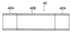
図2に示すように、軟性部50には湾曲部48のすぐ基端側にゴム製のバルーン42が着脱自在に装着されている。バルーン42は、図3に示すように、均一な厚みを有する筒状に形成されており、その内径は軟性部50(図2参照)の外径よりも若干小さく形成されている。そして、挿入部12をバルーン42に押し込むことによって、バルーン42が僅かに膨張されながら軟性部50に嵌挿される。これにより、バルーン42が軟性部50の外周面に密着した状態で装着される。 As shown in FIG. 2, a
バルーン42は、両端部42A、42Aと中央部42Bとで性質の異なるゴム材が使用されており、両端部42A、42Aは、中央部42Bよりも硬度の高いゴム材が使用されている。例えば。両端部42A、42Aのゴム材としてフッ素ゴムやシリコンゴム等が用いられ、中央部42Bのゴム材として天然ゴム等が使用される。なお、両端部42A、42Aと中央部42Bは、別々に成形して接着してもよいし、同時に二層成形してもよい。また、両端部42A、42Aと中央部42Bの硬度が異なるのであれば、同じ種類のゴム材を使用してもよい。例えば、両端部42A、42Aとして硬度が80°Hs程度のシリコンゴムを用い、中央部42Bとして硬度が40°Hs程度のシリコンゴムを用いてもよい。 The
図2に示すように、軟性部50には、バルーン42の中央部42Bの取付位置に通気孔62が形成されている。この通気孔62は、挿入部12内に挿通されたチューブ(不図示)を介して図1の手元操作部14の供給・吸引口44に連通されている。供給・吸引口44にはチューブ64が接続され、このチューブ64がエア圧制御ユニット66に接続される。エア圧制御ユニット66は、チューブ64にエアを供給したり、或いはチューブ64からエアを吸引したりするとともに、その際のエア圧を制御する装置であり、前面に設けられた操作ボタン68によって操作される。したがって、エア圧制御ユニット66を操作することによって、チューブ64を介してバルーン42にエアを供給したり、チューブ64を介してバルーン42からエアを吸引したりすることができる。 As shown in FIG. 2, a
バルーン42にエアを供給すると、図4に示す如く、硬度の低い中央部42Bのみが膨張する。すなわち、硬度の高い端部42A、42Aは膨張せずに軟性部50の外周面に密着した状態のまま、硬度の低い中央部42Bが略球状に膨張する。これにより、通気孔62から供給されたエアがバルーン42の外部に漏れることなく、バルーン42を膨張させることができる。したがって、挿入部12を体腔内の腸管に挿入し、バルーン42を腸管内で膨張させると、バルーン42によって軟性部50を腸管に固定することができる。よって、軟性部50が腸管に固定された状態で、先端部46の先端面47を所望する位置に向けて、観察や各種の処置を行うことができる。その際、バルーン42が軟性部50に装着されているので、バルーン42を膨張させた状態であっても湾曲部48を良好に湾曲操作することができる。なお、バルーン42を装着する位置は、軟性部50に限らず、湾曲部48にかかってもよい。また、先端部46に通気孔62を設けて先端部46にバルーン42を装着するようにしてもよい。 When air is supplied to the
膨張したバルーン42からエアを吸引すると、図4に二点鎖線で示す如く、中央部42Bが収縮し、バルーン42全体が軟性部50の外周面に密着する。バルーン42の厚みは非常に薄いので、軟性部50の外周面には突出部分がなくなる。したがって、挿入部12を体腔内の腸管に挿脱した際に、挿入部12が引っ掛かることがなくなり、挿入部12をスムーズに挿脱することができる。 When air is sucked from the
以上説明したように本実施の形態の内視鏡装置によれば、バルーン42が、均一の厚みを有する筒状に形成されているので、バルーン42に挿入部12を嵌挿させることによって、バルーン42を簡単に挿入部12に装着することができる。 As described above, according to the endoscope apparatus of the present embodiment, since the
また、本実施の形態によれば、バルーン42が挿入部12の外周面に密着した状態で装着されるので、挿入部12の外周面に突出部分がなくなり、体腔内の狭い場所であっても挿入部12をスムーズに挿脱することができる。 Further, according to the present embodiment, since the
さらに、本実施の形態によれば、バルーン42の両端部42A、42Aが中央部42Bよりも硬度の高いゴム材によって構成されるので、バルーン42内にエアを供給することによって中央部42Bのみが膨張し、エアが外部に漏れることを防止できる。 Furthermore, according to the present embodiment, since both
なお、上述した実施の形態では、バルーン42を硬度の異なる二種類のゴム材(すなわち両端部42A、42Aと中央部42B)によって構成したが、硬度の異なる三種類以上のゴム材によって構成してもよく、その場合には、バルーン42の中央に位置するゴム材ほど、硬度が低くなるようにするとよい。例えば、図5(A)に示すバルーン42は、中央部42B、中間部42C、42C、及び両端部42A、42Aで構成されており、これらを構成するゴム材の硬度は、中央部42B<中間部42C、42C<両端部42A、42Aになっている。したがって、通気孔62からエアが供給されると、まず、図5(B)に示すように中央部42Bが膨張し、続いて図5(C)に示すように中間部42C、42Cが膨張する。したがって、バルーン42をその中央位置から順番に膨張させることができるので、両端部42A、42Aでの膨張を防止することができ、両端部42A、42Aにおけるエアの漏れを確実に防止することができる。また、膨張時の大きさを二段階で制御することも可能となる。 In the above-described embodiment, the
また、上述した実施の形態では、バルーン42を硬度の異なる複数のゴム材によって構成したが、バルーン42の両端部から中央部にかけて硬度が徐々に低くなるようなゴム材を用いてもよい。 In the above-described embodiment, the
さらに、上述した実施の形態は、内視鏡10の挿入部12を挿入補助具なしで挿入する例で説明したがこれに限定するものではなく、オーバーチューブ、スライディングチューブ、トラカール等の挿入補助具を用いて挿入してもよい。上述したように本実施の形態の内視鏡10は挿入部12の外周面に突出部分がないので、挿入部12を挿入補助具に対してスムーズに挿脱することができる。 Furthermore, although embodiment mentioned above demonstrated by the example which inserts the
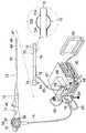
図6は、本発明に係るバルーンを挿入補助具に装着した内視鏡装置のシステム構成図である。 FIG. 6 is a system configuration diagram of an endoscope apparatus in which a balloon according to the present invention is mounted on an insertion aid.
同図に示す挿入補助具70は、ウレタン等からなる樹脂チューブの外側を耐薬コートで被覆するとともに、内側を潤滑コートで保護することによって構成されており、外周面から外力を加えると復元力を発揮するようになっている。また、挿入補助具70の内径は、内視鏡10の挿入部12の外径よりも大きく形成されており、挿入部12を挿入補助具70に挿通できるようになっている。 The
挿入補助具70の先端部には、金属等のX線不透過部材から成るリング(不図示)が設けられており、X線透視で観察した際に、挿入補助具70の先端位置を把握できるようになっている。 A ring (not shown) made of an X-ray opaque member such as metal is provided at the distal end portion of the
また、挿入補助具70の先端外周には、ゴム製のバルーン72が装着されている。バルーン72は、図3に示したバルーン42と同様に、均一な厚みを有する筒状に形成されるとともに、その両端部72A、72Aを構成するゴム材の硬度が、中央部72Bのゴム材の硬度よりも高くなっている。また、バルーン72は、その内径が挿入補助具70の外径よりも若干小さく形成されており、このバルーン72に挿入補助具70を押し込むことによって、バルーン72が挿入補助具70に嵌挿され、挿入補助具70の外周面にバルーン72が密着した状態で装着されるようになっている。 A
バルーン72には、挿入補助具70の外表面に貼着されたチューブ76が連通されており、このチューブ76はコネクタ78を介してチューブ80に接続されている。チューブ80の先端は、前述したエア圧制御ユニット66に接続されており、このエア圧制御ユニット66によって、チューブ80にエアを供給したり、チューブ80からエアを吸引したり、その際のエア圧を制御できるようになっている。これにより、バルーン72にエアを供給したり、バルーン72からエアを吸引したりすることができる。 The
なお、図6の符号84は、水等の潤滑剤を供給するための供給口であり、この供給口84から潤滑材を供給することによって、挿入補助具70と挿入部12との摩擦を減少させることができる。 In addition, the code |
上記の如く構成された内視鏡装置では、バルーン72が、均一の厚みを有する筒状に形成されているので、バルーン72に挿入補助具70を嵌挿させることによって、簡単にバルーン72を装着することができる。また、均一な厚みを有するバルーン72が挿入補助具70の外周面に密着した状態に装着されるので、挿入補助具70の外周面に突出部分がなくなり、体腔内の狭い場所であっても挿入補助具70をスムーズに挿脱することができる。さらに、本実施の形態によれば、バルーン72の両端部72A、72Aが中央部72Bよりもゴム材の硬度が高いので、中央部72Bのみを膨張させることができ、挿入補助具70を体腔内の腸管の所望する位置で固定することができる。 In the endoscope apparatus configured as described above, since the
なお、図6に示す内視鏡10は、挿入部12にバルーンが装着されてないが、これに限定するものではなく、挿入部12にバルーン42(図1参照)を装着してもよい。 In the
10…内視鏡、12…挿入部、14…手元操作部、16…ユニバーサルケーブル、18…LGコネクタ、20…光源装置、22…ケーブル、24…電気コネクタ、26…送気・送水チューブ、28…吸引チューブ、30…プロセッサ、32…送気・送水ボタン、34…吸引ボタン、36…シャッターボタン、38…アングルノブ、40…鉗子挿入部、42…バルーン、44…供給・吸引口、46…先端部、47…先端面、48…湾曲部、50…軟性部、52…観察光学系、54…照明光学系、56…送気・送水ノズル、58…鉗子孔、60…モニタ、62…通気孔、64…チューブ、66…エア圧制御ユニット、68…操作ボタン、70…挿入補助具、72…バルーン、74…把持部、76…チューブ、78…コネクタ、80…チューブ、84…潤滑剤の供給口 DESCRIPTION OF
Claims (1)
Translated fromJapanese前記バルーンは、均一な厚みを有する筒状に形成され、前記挿入部または前記挿入補助具に嵌挿されるとともに、
両端部が中央部よりも高い硬度のゴム材によって構成されることを特徴とする内視鏡装置用のバルーン。In a balloon for an endoscope apparatus that is attached to an insertion portion of an endoscope or an insertion assisting tool that covers the insertion portion, and expands when supplied with fluid,
The balloon is formed in a cylindrical shape having a uniform thickness, and is inserted into the insertion portion or the insertion aid,
A balloon for an endoscope apparatus, characterized in that both end portions are made of a rubber material having a hardness higher than that of the central portion.
Priority Applications (1)
| Application Number | Priority Date | Filing Date | Title |
|---|---|---|---|
| JP2003358085AJP3774901B2 (en) | 2003-10-17 | 2003-10-17 | Balloon for endoscopic device |
Applications Claiming Priority (1)
| Application Number | Priority Date | Filing Date | Title |
|---|---|---|---|
| JP2003358085AJP3774901B2 (en) | 2003-10-17 | 2003-10-17 | Balloon for endoscopic device |
Publications (2)
| Publication Number | Publication Date |
|---|---|
| JP2005118375A JP2005118375A (en) | 2005-05-12 |
| JP3774901B2true JP3774901B2 (en) | 2006-05-17 |
Family
ID=34614779
Family Applications (1)
| Application Number | Title | Priority Date | Filing Date |
|---|---|---|---|
| JP2003358085AExpired - Fee RelatedJP3774901B2 (en) | 2003-10-17 | 2003-10-17 | Balloon for endoscopic device |
Country Status (1)
| Country | Link |
|---|---|
| JP (1) | JP3774901B2 (en) |
Families Citing this family (4)
| Publication number | Priority date | Publication date | Assignee | Title |
|---|---|---|---|---|
| JP4505345B2 (en) | 2004-03-31 | 2010-07-21 | オリンパス株式会社 | Endoscope insertion assisting probe and endoscope apparatus to which the probe is applied |
| JP4836653B2 (en)* | 2006-04-28 | 2011-12-14 | 富士フイルム株式会社 | Endoscope device |
| JP6461852B2 (en)* | 2016-04-28 | 2019-01-30 | スマート・メディカル・システムズ・リミテッド | Endoscopy tools |
| JP7170599B2 (en) | 2019-08-09 | 2022-11-14 | 富士フイルム株式会社 | Endoscope device and balloon |
- 2003
- 2003-10-17JPJP2003358085Apatent/JP3774901B2/ennot_activeExpired - Fee Related
Also Published As
| Publication number | Publication date |
|---|---|
| JP2005118375A (en) | 2005-05-12 |
Similar Documents
| Publication | Publication Date | Title |
|---|---|---|
| JP5095124B2 (en) | Endoscope | |
| EP1759627B1 (en) | Hood for endoscope, endoscope and method of fixing balloon for endoscope | |
| JP3877075B2 (en) | Endoscope device | |
| JP3804068B2 (en) | Endoscope insertion aid | |
| JP4836653B2 (en) | Endoscope device | |
| JP2005312904A (en) | Endoscope apparatus | |
| JP2006230950A (en) | Endoscope apparatus | |
| JP5116985B2 (en) | Endoscope | |
| JP2008220775A (en) | Endoscope apparatus | |
| JP2007268137A (en) | Endoscopic equipment for large intestine | |
| JP2006271992A (en) | Double balloon type endoscope device | |
| JP6147710B2 (en) | Endoscope hood and endoscope system | |
| JP3826928B2 (en) | Endoscope insertion aid | |
| JP3774901B2 (en) | Balloon for endoscopic device | |
| JP3804069B1 (en) | Balloon, endoscope equipped with the same, insertion aid, and endoscope apparatus | |
| JP3873968B2 (en) | Endoscope overtube | |
| JP3794492B2 (en) | Endoscope | |
| JP3753327B2 (en) | Endoscope | |
| JP3787724B2 (en) | Endoscope device | |
| JP4776312B2 (en) | Endoscope device | |
| JP3812675B2 (en) | Endoscope balloon fixing method and structure | |
| JP3864345B2 (en) | Endoscope insertion aid | |
| JP4786985B2 (en) | Endoscope | |
| JP2007330468A (en) | Cover for endoscope and endoscope device furnished with it | |
| JP3888379B2 (en) | Insertion aid and endoscope device |
Legal Events
| Date | Code | Title | Description |
|---|---|---|---|
| A621 | Written request for application examination | Free format text:JAPANESE INTERMEDIATE CODE: A621 Effective date:20051005 | |
| A871 | Explanation of circumstances concerning accelerated examination | Free format text:JAPANESE INTERMEDIATE CODE: A871 Effective date:20051226 | |
| A975 | Report on accelerated examination | Free format text:JAPANESE INTERMEDIATE CODE: A971005 Effective date:20060118 | |
| TRDD | Decision of grant or rejection written | ||
| A01 | Written decision to grant a patent or to grant a registration (utility model) | Free format text:JAPANESE INTERMEDIATE CODE: A01 Effective date:20060130 | |
| A61 | First payment of annual fees (during grant procedure) | Free format text:JAPANESE INTERMEDIATE CODE: A61 Effective date:20060212 | |
| R150 | Certificate of patent or registration of utility model | Free format text:JAPANESE INTERMEDIATE CODE: R150 | |
| FPAY | Renewal fee payment (event date is renewal date of database) | Free format text:PAYMENT UNTIL: 20090303 Year of fee payment:3 | |
| FPAY | Renewal fee payment (event date is renewal date of database) | Free format text:PAYMENT UNTIL: 20100303 Year of fee payment:4 | |
| FPAY | Renewal fee payment (event date is renewal date of database) | Free format text:PAYMENT UNTIL: 20100303 Year of fee payment:4 | |
| S111 | Request for change of ownership or part of ownership | Free format text:JAPANESE INTERMEDIATE CODE: R313113 | |
| R371 | Transfer withdrawn | Free format text:JAPANESE INTERMEDIATE CODE: R371 | |
| S111 | Request for change of ownership or part of ownership | Free format text:JAPANESE INTERMEDIATE CODE: R313113 | |
| FPAY | Renewal fee payment (event date is renewal date of database) | Free format text:PAYMENT UNTIL: 20100303 Year of fee payment:4 | |
| R350 | Written notification of registration of transfer | Free format text:JAPANESE INTERMEDIATE CODE: R350 | |
| FPAY | Renewal fee payment (event date is renewal date of database) | Free format text:PAYMENT UNTIL: 20100303 Year of fee payment:4 | |
| FPAY | Renewal fee payment (event date is renewal date of database) | Free format text:PAYMENT UNTIL: 20110303 Year of fee payment:5 | |
| FPAY | Renewal fee payment (event date is renewal date of database) | Free format text:PAYMENT UNTIL: 20110303 Year of fee payment:5 | |
| FPAY | Renewal fee payment (event date is renewal date of database) | Free format text:PAYMENT UNTIL: 20120303 Year of fee payment:6 | |
| FPAY | Renewal fee payment (event date is renewal date of database) | Free format text:PAYMENT UNTIL: 20120303 Year of fee payment:6 | |
| FPAY | Renewal fee payment (event date is renewal date of database) | Free format text:PAYMENT UNTIL: 20130303 Year of fee payment:7 | |
| FPAY | Renewal fee payment (event date is renewal date of database) | Free format text:PAYMENT UNTIL: 20130303 Year of fee payment:7 | |
| FPAY | Renewal fee payment (event date is renewal date of database) | Free format text:PAYMENT UNTIL: 20140303 Year of fee payment:8 | |
| R250 | Receipt of annual fees | Free format text:JAPANESE INTERMEDIATE CODE: R250 | |
| LAPS | Cancellation because of no payment of annual fees |