JP3773094B2 - Rear body structure of the vehicle - Google Patents
Rear body structure of the vehicleDownload PDFInfo
- Publication number
- JP3773094B2 JP3773094B2JP2000143896AJP2000143896AJP3773094B2JP 3773094 B2JP3773094 B2JP 3773094B2JP 2000143896 AJP2000143896 AJP 2000143896AJP 2000143896 AJP2000143896 AJP 2000143896AJP 3773094 B2JP3773094 B2JP 3773094B2
- Authority
- JP
- Japan
- Prior art keywords
- vehicle
- package tray
- hollow member
- body structure
- vicinity
- Prior art date
- Legal status (The legal status is an assumption and is not a legal conclusion. Google has not performed a legal analysis and makes no representation as to the accuracy of the status listed.)
- Expired - Fee Related
Links
- 238000000465mouldingMethods0.000claimsdescription12
- 239000000725suspensionSubstances0.000claimsdescription8
- 238000005192partitionMethods0.000claimsdescription5
- 230000004048modificationEffects0.000description10
- 238000012986modificationMethods0.000description10
- 229910000831SteelInorganic materials0.000description9
- 238000000034methodMethods0.000description9
- 239000010959steelSubstances0.000description9
- 238000010586diagramMethods0.000description5
- 230000002787reinforcementEffects0.000description3
- 230000000694effectsEffects0.000description2
- 239000007788liquidSubstances0.000description2
- 239000003381stabilizerSubstances0.000description2
- 239000000853adhesiveSubstances0.000description1
- 230000001070adhesive effectEffects0.000description1
- 238000007796conventional methodMethods0.000description1
- 238000005516engineering processMethods0.000description1
- 239000002184metalSubstances0.000description1
- XLYOFNOQVPJJNP-UHFFFAOYSA-NwaterSubstancesOXLYOFNOQVPJJNP-UHFFFAOYSA-N0.000description1
- 238000003466weldingMethods0.000description1
Images


Landscapes
- Body Structure For Vehicles (AREA)
- Shaping Metal By Deep-Drawing, Or The Like (AREA)
Description
Translated fromJapanese【0001】
【発明の属する技術分野】
本発明は、車両の後部車体構造に関し、例えば代表的な車両であるセダンタイプの自動車に採用して好適な後部車体構造に関する。
【0002】
【従来の技術】
近年、所謂ハイドロフォームによる金属部材の成型方法が自動車の分野において各種提案されており、この技術を利用した部材の成型方法としては、例えば、ハイドロフォームにより形成されたレインフォースメントを、車体のピラー内部に接合する技術が特開平10−218017号に提案されている。また、特開平11−235963号には、ハイドロフォームにより形成されたレインフォースメントを、車体のサイドフレーム内部に接合する技術が提案されており、この他にも、ハイドロフォームによって車体各部の金属部材が成型されつつある。
【0003】
ハイドロフォームは、金型に入れた高張力鋼管の内部に液体(油や水等)を満たし、その状態において液体に加える圧力を高めることにより、高張力鋼管を所望の形状に成型する(膨らませる)手法であり、係る手法によれば、鋼板をプレスした複数の部材を溶接することによって所望の部材形状を得る従来の手法よりも軽量且つ高剛性の部材を得ることができる。
【0004】
【発明が解決しようとする課題】
ここで、代表的な車両である一般的なセダンタイプの自動車において、車室と荷室とを仕切るリアパッケージトレイ周辺の一般的な構造について概説する。
【0005】
図12は、自動車のリアパッケージトレイ周辺の一般的な構造を示す要部断面図である。
【0006】
セダンタイプの自動車には、同図に示すように、リアウインド15に近接した位置において、車室と荷室とを仕切るリアパッケージトレイ11が設けられている。このリアパッケージトレイ11は、リアウィンドウ15が接合されると共に、後輪のサスペンション及びリアピラーの近傍でもあり、更にリアシートバックへの乗員の荷重も加えられるため、確かな剛性を要求される部分である。このため、リアパッケージトレイ11には、補強用のフロントメンバ13やリアメンバ12等が車幅方向に接合される。
【0007】
このように、リアパッケージトレイ周辺は、車体剛性にも寄与すべき部分であるが、周囲にはリアウィンドウ、タイヤハウス、リアピラー等が接合される狭い空間であるため、例えばハイドロフォームを適用することにより、支持剛性を低下させることなく、部品点数の削減や軽量化等が望まれる。
【0008】
そこで本発明は、軽量で支持剛性に優れる車両の後部車体構造の提供を目的とする。
【0009】
【課題を解決するための手段】
上記の目的を達成するため、本発明に係る車両の後部車体構造は、以下の構成を特徴とする。
【0010】
即ち、車体後部の開口を塞ぐリアウインドに近接して設けられ、車室と荷室とを仕切るリアパッケージトレイを備える車両の後部車体構造であって、前記リアパッケージトレイには、管状部材より成型された、一体成型品である第1及び第2中空部材が接合されており、前記第1中空部材は、中間部が、前記リアパッケージトレイの車両後方側の縁部外側において車幅方向に延設されると共に、両端が、前記車体後部のリアピラー内側において、前記リアパッケージトレイの成型形状に沿って、その成型形状の上部を車両前方方向に向かって延設され、前記第2中空部材は、前記リアパッケージトレイの車両前方側の縁部内側において、車幅方向に延設され、前記第1中空部材には前記リアウインドが直接接合され、前記リアパッケージトレイには、前記後輪のタイヤハウス近傍において切り欠き部を有し、前記第2中空部材の両端は、前記リアパッケージトレイの縁部内側から前記切り欠き部を通って車室側に露出すると共に、前記第1中空部材の両端近傍に直接接合されていることを特徴とする。
【0011】
好適な実施形態において、前記第1中空部材の両端は、前記車両の後輪を支持するサスペンションタワーの頂上部近傍まで延設すると良い。
【0013】
【発明の効果】
上記の本発明によれば、軽量で支持剛性に優れる車両の後部車体構造の提供が実現する。
【0014】
即ち、請求項1の発明によれば、2つの中空部材によって十分な剛性を確保することができるため、その剛性に応じて、リアパッケージトレイに採用すべき鋼板の厚さを薄くすることができ、軽量化を図ることができると共に、車体全体の剛性を向上することができる。また、リアパッケージトレイの縁部に沿って第1及び第2中空部材がロの字状の構造をなすことにより、車体全体の剛性の向上に更に寄与することができる。
【0015】
また、請求項2の発明によれば、第1中空部材がスタビライザーとして機能するため、サスペンションの支持剛性を向上することができる。
【0017】
【発明の実施の形態】
以下、本発明に係る車両の後部車体構造の一実施形態を、図面を参照して詳細に説明する。
【0018】
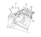
図1は、本実施形態における車両の後部車体構造を示す斜視図であり、理解を容易にすべく一部を断面にて示している。
【0019】
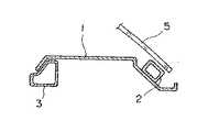
また、図3は、図1のB−B断面を示す要部断面図、そして図5は、図1のC−C断面を示す要部断面図であり、何れの図も車体前後方向に切断した場合を示している。また、図4は、図1のA−A断面を示す要部断面図であり、車幅方向に切断した場合を示している。
【0020】
これらの図において、1は、例えばセダンタイプの車体後部の開口を塞ぐリアウインド5に近接して設けられ、車室と荷室とを仕切るリアパッケージトレイである。
【0021】
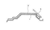
リアパッケージトレイ1には、図2に示す形状に成型されたリア中空部材2とフロント中空部材3とが接合されている。
【0022】
即ち、リア中空部材2は、その中間部が、図1及び図3に示すように、リアパッケージトレイ1の車両後方側の縁部外側において車幅方向に延設されると共に、その両端は、図4及び図5に示すように、リアピラー(Cピラー)インナ4近傍におけるリアパッケージトレイ1の成型形状に沿って、その上部を車両前方方向に向かって、車両の後輪を支持するサスペンションタワーの頂上部近傍(トリム8の内側のホイルハウスインナ6の頂上部分)まで延設されている。また、リア中空部材2には、図3に示すようにリアウィンドウ5が接着剤によって直接接合される。
【0023】
一方、フロント中空部材3は、図1及び図3に示すように、リアパッケージトレイ1の車両前方側の縁部内側に、車幅方向に接合されている。
【0024】
尚、リア中空部材2とフロント中空部材3とは、後述するハイドロフォームによって管状部材より成型した部材である。
【0025】
本実施形態によれば、リア中空部材2とフロント中空部材3とによって十分な剛性を確保することができるため、その剛性に応じて、リアパッケージトレイ1に採用すべき鋼板の厚さを薄くすることができ、軽量化を図ることができると共に、車体全体の剛性を向上することができる。
【0026】
また、リア中空部材2の両端がサスペンションタワーの頂上部近傍まで延設されているため、リア中空部材2をスタビライザーとして機能させることができ、サスペンションの支持剛性を向上することができる。このため、サスペンションを支持する部材を削減及び/または軽量化することも可能となる。
【0027】
<実施形態の変形例>
次に、上述した実施形態においては、リアパッケージトレイ1に接合されたリア中空部材2とフロント中空部材3とは別体であったが、本変形例においては、これらの中空部材を一体に接合する場合について説明する。
【0028】
図6は、本実施形態の変形例における車両の後部車体構造を示す斜視図であり、図1の場合と同様に一部を断面にて示している。図7は、本実施形態の変形例における中空部材の接合構造を示す斜視図である。そして図8は、図6のD−D断面を示す要部断面図であり、車体前後方向に切断した場合を示している。
【0029】
図6において、本変形例に係るリアパッケージトレイ1A、フロント中空部材3A、並びにリア中空部材2Aの形状は、断面A−A,断面B−B,断面C−Cにおいて、上述した実施形態で参照した図3乃至図5と同じ形状である。
【0030】
但し、フロント中空部材3Aとリア中空部材2Aとは、図7に示すように、ロの字状の構造を含む形状に一体に接合されている。即ち、本変形例において、リアパッケージトレイ1Aには、図6及び図8に示すように、後輪のタイヤハウス近傍において切り欠き部が設けられており、フロント中空部材3Aの両端は、リアパッケージトレイ1Aの縁部内側から当該切り欠き部を通って車室側に露出すると共に、リア中空部材2Aの両端近傍において接合されている。
【0031】
本変形例によれば、上述した実施形態と同様な効果を享受することができると共に、フロント中空部材3Aとリア中空部材2Aとが一体に接合されて、リアパッケージトレイ1Aの縁部に沿ってロの字状の構造を含むため、車体全体の剛性の向上に更に寄与することができる。
【0032】
ここで、上述した第1の実施形態及びその変形例において採用したハイドロフォームによるリア中空部材2,2Aと、フロント中空部材3,3Aの成型方法について概説する。
【0033】
図9は、ハイドロフォーム成型設備を説明する図である。また、図10及び図11は、ハイドロフォームによる成型方法を説明する図である。
【0034】
油圧プレス機102の下方に配置される上型103及び下型104は、予め所望の形状(上述したリア中空部材2,2Aと、フロント中空部材3,3Aの外形形状)に成型する。
【0035】
次に、上型103及び下型104の間に、図11に示す如く高張力鋼管106をセットし、上方から油圧プレス機102によって押圧すると共に、高張力鋼管106の内部に、図12に示すように油圧ユニット101から油圧ライン105を介して油を充填させ、その状態において油圧を高める。この高圧な油圧により、高張力鋼管106は、上型103及び下型104に沿って所望の形状(上述したリア中空部材2,2Aと、フロント中空部材3,3A)に成型される(膨らまされる)。
【0036】
以上説明したように、上述した実施形態及びぞの変形例によれば、軽量で支持剛性に優れる車両の後部車体構造の提供が実現する。
【図面の簡単な説明】
【図1】本実施形態における車両の後部車体構造を示す斜視図である。
【図2】本実施形態における2つの中空部材の形状を示す斜視図である。
【図3】図1のB−B断面を示す要部断面図である。
【図4】図1のA−A断面を示す要部断面図である。
【図5】図1のC−C断面を示す要部断面図である。
【図6】本実施形態の変形例における車両の後部車体構造を示す斜視図である。
【図7】本実施形態の変形例における中空部材の接合構造を示す斜視図である。
【図8】図6のD−D断面を示す要部断面図である。
【図9】ハイドロフォーム成型設備を説明する図である。
【図10】ハイドロフォームによる成型方法を説明する図である。
【図11】ハイドロフォームによる成型方法を説明する図である。
【図12】自動車のリアパッケージトレイ周辺の一般的な構造を示す要部断面図である。
【符号の説明】
1,1A,11:リアパッケージトレイ,
2,2A:リア中空部材,
3,3A:フロント中空部材,
4:リアピラーインナ,
5,15A:リアウィンドウ,
6:ホイルハウスインナ,
7:アウターパネル,
8:トリム,
12:フロントメンバ,
13:リアメンバ,
101:油圧ユニット,
102:油圧プレス機,
103:上型,
104:下型,
105:油圧ライン,
106:高張力鋼管,[0001]
BACKGROUND OF THE INVENTION
The present invention relates to a rear vehicle body structure of a vehicle, for example, a rear vehicle body structure suitable for use in a sedan type automobile which is a typical vehicle.
[0002]
[Prior art]
In recent years, various so-called hydroforming molding methods for metal members have been proposed in the field of automobiles. Examples of molding methods using this technology include, for example, a reinforcement formed by hydroforming, a pillar of a vehicle body. A technique for joining inside is proposed in Japanese Patent Laid-Open No. 10-218017. Japanese Patent Application Laid-Open No. 11-235963 proposes a technique for joining a reinforcement formed by hydroforming to the inside of a side frame of the vehicle body. Is being molded.
[0003]
Hydroform fills a liquid (oil, water, etc.) inside a high-tensile steel pipe placed in a mold and increases the pressure applied to the liquid in that state, thereby forming (expanding) the high-tensile steel pipe into a desired shape. According to this method, a lighter and more rigid member can be obtained than the conventional method of obtaining a desired member shape by welding a plurality of members pressed on a steel plate.
[0004]
[Problems to be solved by the invention]
Here, the general structure around the rear package tray that partitions the compartment and the luggage compartment in a typical sedan type automobile that is a typical vehicle will be outlined.
[0005]
FIG. 12 is a cross-sectional view of a main part showing a general structure around the rear package tray of an automobile.
[0006]
As shown in the figure, the sedan type automobile is provided with a rear package tray 11 that partitions the vehicle compartment and the cargo compartment at a position close to the
[0007]
In this way, the periphery of the rear package tray is a part that should also contribute to the rigidity of the vehicle body, but since the periphery is a narrow space where the rear window, tire house, rear pillar, etc. are joined, for example, hydroform should be applied Therefore, it is desired to reduce the number of parts and reduce the weight without reducing the support rigidity.
[0008]
Therefore, an object of the present invention is to provide a rear body structure of a vehicle that is lightweight and excellent in support rigidity.
[0009]
[Means for Solving the Problems]
In order to achieve the above object, a vehicle rear body structure according to the present invention is characterized by the following configuration.
[0010]
That is, a rear vehicle body structure of a vehicle including a rear package tray that is provided in the vicinity of a rear window that closes an opening at a rear portion of the vehicle body and partitions a vehicle compartment and a cargo compartment. The rear package tray is molded from a tubular member. The first and second hollow members, which are integrally molded products, are joined, and the intermediate portion of the first hollow member extends in the vehicle width direction outside the edge of the rear package tray on the vehicle rear side. And both ends are extended along the molding shape of the rear package tray along the molding shape of the rear package tray toward the front side of the vehicle inside the rear pillar at the rear of the vehicle body, and the second hollow member is the rear package tray of the vehicle front-side edgeOite inwardlyextends in the vehicle width direction, wherein the rear window is bonded directly to the first hollowmember, the rear package tray And having a notch in the vicinity of the tire house of the rear wheel, and both ends of the second hollow member are exposed from the inner side of the edge of the rear package tray to the vehicle compartment side through the notch. The first hollow member is directly joined in the vicinity of both ends .
[0011]
In a preferred embodiment, both ends of the first hollow member may extend to the vicinity of the top of a suspension tower that supports a rear wheel of the vehicle.
[0013]
【The invention's effect】
According to the present invention described above, it is possible to provide a rear vehicle body structure that is lightweight and has excellent support rigidity.
[0014]
That is, according to the invention of
[0015]
According to the invention of
[0017]
DETAILED DESCRIPTION OF THE INVENTION
Hereinafter, an embodiment of a rear body structure of a vehicle according to the present invention will be described in detail with reference to the drawings.
[0018]
FIG. 1 is a perspective view showing a rear body structure of a vehicle in the present embodiment, and a part thereof is shown in cross section for easy understanding.
[0019]
3 is a cross-sectional view of the main part showing the cross section BB of FIG. 1, and FIG. 5 is a cross-sectional view of the main part showing the cross section CC of FIG. Shows the case. FIG. 4 is a cross-sectional view of the main part showing the AA cross section of FIG. 1, and shows a case of cutting in the vehicle width direction.
[0020]
In these drawings,
[0021]
A rear
[0022]
That is, as shown in FIGS. 1 and 3, the rear
[0023]
On the other hand, as shown in FIGS. 1 and 3, the front
[0024]
The rear
[0025]
According to the present embodiment, sufficient rigidity can be ensured by the rear
[0026]
Further, since both ends of the rear
[0027]
<Modification of Embodiment>
Next, in the above-described embodiment, the rear
[0028]
FIG. 6 is a perspective view showing a rear body structure of a vehicle according to a modified example of the present embodiment, and shows a part in a cross section as in the case of FIG. FIG. 7 is a perspective view showing a joining structure of hollow members in a modification of the present embodiment. FIG. 8 is a cross-sectional view of the main part showing the DD cross section of FIG. 6 and shows a case where it is cut in the longitudinal direction of the vehicle body.
[0029]
In FIG. 6, the shapes of the
[0030]
However, as shown in FIG. 7, the front
[0031]
According to this modification, the same effect as that of the above-described embodiment can be enjoyed, and the front
[0032]
Here, an outline of the molding method of the rear
[0033]
FIG. 9 is a diagram illustrating a hydroform molding facility. 10 and 11 are diagrams for explaining a molding method using hydroform.
[0034]
The
[0035]
Next, a high-
[0036]
As described above, according to the above-described embodiment and each modification, it is possible to provide a rear vehicle body structure that is lightweight and has excellent support rigidity.
[Brief description of the drawings]
FIG. 1 is a perspective view showing a rear body structure of a vehicle according to an embodiment.
FIG. 2 is a perspective view showing the shapes of two hollow members in the present embodiment.
3 is a cross-sectional view of a principal part showing a cross section taken along the line BB of FIG. 1;
4 is a cross-sectional view of the main part showing the AA cross section of FIG. 1. FIG.
FIG. 5 is a cross-sectional view of a principal part showing a cross section taken along the line CC of FIG. 1;
FIG. 6 is a perspective view showing a rear body structure of a vehicle according to a modification of the embodiment.
FIG. 7 is a perspective view showing a joining structure of hollow members in a modification of the present embodiment.
8 is a cross-sectional view of a principal part showing a DD cross section of FIG. 6;
FIG. 9 is a diagram illustrating a hydroform molding facility.
FIG. 10 is a diagram illustrating a molding method using hydroform.
FIG. 11 is a diagram illustrating a molding method using hydroform.
FIG. 12 is a cross-sectional view of a main part showing a general structure around a rear package tray of an automobile.
[Explanation of symbols]
1, 1A, 11: Rear package tray,
2, 2A: Rear hollow member,
3, 3A: Front hollow member,
4: Rear pillar inner,
5, 15A: Rear window,
6: Wheelhouse Inner,
7: Outer panel,
8: Trim,
12: Front member,
13: Rear member,
101: Hydraulic unit,
102: Hydraulic press machine,
103: Upper mold,
104: Lower mold,
105: Hydraulic line,
106: High tensile steel pipe,
Claims (3)
Translated fromJapanese前記リアパッケージトレイには、管状部材より成型された、一体成型品である第1及び第2中空部材が接合されており、
前記第1中空部材は、中間部が、前記リアパッケージトレイの車両後方側の縁部外側において車幅方向に延設されると共に、両端が、前記車体後部のリアピラー内側において、前記リアパッケージトレイの成型形状に沿って、その成型形状の上部を車両前方方向に向かって延設され、
前記第2中空部材は、前記リアパッケージトレイの車両前方側の縁部内側において、車幅方向に延設され、
前記第1中空部材には前記リアウインドが直接接合され、
前記リアパッケージトレイには、前記後輪のタイヤハウス近傍において切り欠き部を有し、
前記第2中空部材の両端は、前記リアパッケージトレイの縁部内側から前記切り欠き部を通って車室側に露出すると共に、前記第1中空部材の両端近傍に直接接合されていることを特徴とする車両の後部車体構造。A rear vehicle body structure of a vehicle provided with a rear package tray that is provided in the vicinity of a rear window that closes an opening at the rear of the vehicle body and partitions a vehicle compartment and a cargo compartment,
The rear package tray is joined with the first and second hollow members that are molded from a tubular member and are integrally molded,
The first hollow member has an intermediate portion extending in the vehicle width direction outside the edge of the rear package tray on the vehicle rear side, and both ends inside the rear pillar at the rear of the vehicle body, Along the molding shape, the upper part of the molding shape is extended toward the front of the vehicle,
Said second hollow member, the rear package tray of the vehicle front-side edgeOite inwardlyextends in the vehicle width direction,
The rear window is directly joined to the first hollow member,
The rear package tray has a notch in the vicinity of the tire house of the rear wheel,
Both ends of the second hollow member are exposed from the inner side of the edge of the rear package tray through the notch to the passenger compartment side, and are directly joined to the vicinity of both ends of the first hollow member. The rear body structure of the vehicle.
Priority Applications (1)
| Application Number | Priority Date | Filing Date | Title |
|---|---|---|---|
| JP2000143896AJP3773094B2 (en) | 2000-05-16 | 2000-05-16 | Rear body structure of the vehicle |
Applications Claiming Priority (1)
| Application Number | Priority Date | Filing Date | Title |
|---|---|---|---|
| JP2000143896AJP3773094B2 (en) | 2000-05-16 | 2000-05-16 | Rear body structure of the vehicle |
Publications (2)
| Publication Number | Publication Date |
|---|---|
| JP2001322564A JP2001322564A (en) | 2001-11-20 |
| JP3773094B2true JP3773094B2 (en) | 2006-05-10 |
Family
ID=18650643
Family Applications (1)
| Application Number | Title | Priority Date | Filing Date |
|---|---|---|---|
| JP2000143896AExpired - Fee RelatedJP3773094B2 (en) | 2000-05-16 | 2000-05-16 | Rear body structure of the vehicle |
Country Status (1)
| Country | Link |
|---|---|
| JP (1) | JP3773094B2 (en) |
Families Citing this family (3)
| Publication number | Priority date | Publication date | Assignee | Title |
|---|---|---|---|---|
| JP4114002B2 (en)* | 2002-04-23 | 2008-07-09 | マツダ株式会社 | Rear body structure of automobile |
| FR3030433B1 (en)* | 2014-12-19 | 2017-02-10 | Plastic Omnium Cie | REAR SHELF OF A MOTOR VEHICLE OF COMPOSITE MATERIAL |
| JP6973001B2 (en)* | 2017-12-08 | 2021-11-24 | トヨタ自動車株式会社 | Vehicle composite parts, vehicles, vehicle manufacturing methods, and mixed flow production methods |
Family Cites Families (10)
| Publication number | Priority date | Publication date | Assignee | Title |
|---|---|---|---|---|
| JPS6116175A (en)* | 1984-07-04 | 1986-01-24 | Nissan Motor Co Ltd | car body structure |
| JPS61117066U (en)* | 1985-01-09 | 1986-07-24 | ||
| JPH0352614Y2 (en)* | 1985-03-30 | 1991-11-14 | ||
| JPH0416778Y2 (en)* | 1986-10-07 | 1992-04-15 | ||
| JPS63168169U (en)* | 1987-04-23 | 1988-11-01 | ||
| JPH0245884U (en)* | 1988-09-26 | 1990-03-29 | ||
| JPH0736871Y2 (en)* | 1988-11-25 | 1995-08-23 | トヨタ自動車株式会社 | Car body structure |
| JP3143999B2 (en)* | 1991-11-15 | 2001-03-07 | トヨタ自動車株式会社 | Car upper back structure |
| DE19630647A1 (en)* | 1996-07-30 | 1998-02-05 | Porsche Ag | Suspension strut mount for a motor vehicle, especially a passenger car |
| JPH11235963A (en)* | 1998-02-20 | 1999-08-31 | Isuzu Motors Ltd | Side sill reinforcing structure of cab |
- 2000
- 2000-05-16JPJP2000143896Apatent/JP3773094B2/ennot_activeExpired - Fee Related
Also Published As
| Publication number | Publication date |
|---|---|
| JP2001322564A (en) | 2001-11-20 |
Similar Documents
| Publication | Publication Date | Title |
|---|---|---|
| JP3976198B2 (en) | Body front structure | |
| JP5550367B2 (en) | Vehicle roof column assembly | |
| JP3074643B2 (en) | Car body side wall | |
| US9616935B2 (en) | Vehicle structures and methods of assembling the same | |
| US6705667B1 (en) | Supporting structure for a motor vehicle | |
| JP4636799B2 (en) | Support structure made of hollow steel long section material for automobile | |
| US8517458B2 (en) | Hydroformed automotive pillar | |
| JP6460135B2 (en) | Vehicle side body structure | |
| JP3632903B2 (en) | Front body structure of the vehicle | |
| JP2005532207A5 (en) | ||
| KR20080011316A (en) | Tubular member of piece with integral welding flange and manufacturing method thereof | |
| US20020057004A1 (en) | Frame assembly for a motor vehicle | |
| US7032958B2 (en) | Body and frame assembly for a vehicle and method of assembling a vehicle | |
| JP2010023661A (en) | Vehicle body front structure | |
| JP4556320B2 (en) | Lower body structure of the vehicle | |
| JP3773094B2 (en) | Rear body structure of the vehicle | |
| US7540558B2 (en) | Door pillar for a supporting structure | |
| JP7307043B2 (en) | car body | |
| US7789429B2 (en) | Bodywork structure of a motor vehicle with a suspension strut dome | |
| JP4277187B2 (en) | Rear body structure of the vehicle | |
| JP3889741B2 (en) | Body structure | |
| JP3707283B2 (en) | Auto body structure | |
| JP4118004B2 (en) | Hydroform molded product, hydroform molding method of the molded product, and vehicle body member using hydroform molded product | |
| JP3330703B2 (en) | Car side body structure | |
| JPH06321138A (en) | Vehicle body structure of automobile |
Legal Events
| Date | Code | Title | Description |
|---|---|---|---|
| A977 | Report on retrieval | Free format text:JAPANESE INTERMEDIATE CODE: A971007 Effective date:20050119 | |
| A131 | Notification of reasons for refusal | Free format text:JAPANESE INTERMEDIATE CODE: A131 Effective date:20050207 | |
| A521 | Written amendment | Free format text:JAPANESE INTERMEDIATE CODE: A523 Effective date:20050323 | |
| A131 | Notification of reasons for refusal | Free format text:JAPANESE INTERMEDIATE CODE: A131 Effective date:20050704 | |
| A521 | Written amendment | Free format text:JAPANESE INTERMEDIATE CODE: A523 Effective date:20050825 | |
| TRDD | Decision of grant or rejection written | ||
| A01 | Written decision to grant a patent or to grant a registration (utility model) | Free format text:JAPANESE INTERMEDIATE CODE: A01 Effective date:20060127 | |
| A61 | First payment of annual fees (during grant procedure) | Free format text:JAPANESE INTERMEDIATE CODE: A61 Effective date:20060209 | |
| R150 | Certificate of patent or registration of utility model | Free format text:JAPANESE INTERMEDIATE CODE: R150 | |
| FPAY | Renewal fee payment (event date is renewal date of database) | Free format text:PAYMENT UNTIL: 20100224 Year of fee payment:4 | |
| FPAY | Renewal fee payment (event date is renewal date of database) | Free format text:PAYMENT UNTIL: 20100224 Year of fee payment:4 | |
| FPAY | Renewal fee payment (event date is renewal date of database) | Free format text:PAYMENT UNTIL: 20110224 Year of fee payment:5 | |
| FPAY | Renewal fee payment (event date is renewal date of database) | Free format text:PAYMENT UNTIL: 20120224 Year of fee payment:6 | |
| FPAY | Renewal fee payment (event date is renewal date of database) | Free format text:PAYMENT UNTIL: 20130224 Year of fee payment:7 | |
| FPAY | Renewal fee payment (event date is renewal date of database) | Free format text:PAYMENT UNTIL: 20140224 Year of fee payment:8 | |
| LAPS | Cancellation because of no payment of annual fees |