JP3772617B2 - Health care guideline advice device - Google Patents
Health care guideline advice deviceDownload PDFInfo
- Publication number
- JP3772617B2 JP3772617B2JP34149099AJP34149099AJP3772617B2JP 3772617 B2JP3772617 B2JP 3772617B2JP 34149099 AJP34149099 AJP 34149099AJP 34149099 AJP34149099 AJP 34149099AJP 3772617 B2JP3772617 B2JP 3772617B2
- Authority
- JP
- Japan
- Prior art keywords
- angle
- health management
- guideline advice
- measurement
- advice device
- Prior art date
- Legal status (The legal status is an assumption and is not a legal conclusion. Google has not performed a legal analysis and makes no representation as to the accuracy of the status listed.)
- Expired - Fee Related
Links
- 238000002847impedance measurementMethods0.000claimsdescription15
- 238000001514detection methodMethods0.000claimsdescription8
- 210000000577adipose tissueAnatomy0.000description97
- 238000005259measurementMethods0.000description95
- 238000000034methodMethods0.000description19
- 238000010586diagramMethods0.000description12
- 230000001133accelerationEffects0.000description11
- 238000003825pressingMethods0.000description9
- 239000000758substrateSubstances0.000description7
- 235000019577caloric intakeNutrition0.000description3
- 239000004020conductorSubstances0.000description3
- 210000004247handAnatomy0.000description3
- 235000001916dietingNutrition0.000description2
- 230000037228dieting effectEffects0.000description2
- 230000000694effectsEffects0.000description2
- 210000003813thumbAnatomy0.000description2
- 125000002066L-histidyl groupChemical group[H]N1C([H])=NC(C([H])([H])[C@](C(=O)[*])([H])N([H])[H])=C1[H]0.000description1
- 208000008589ObesityDiseases0.000description1
- 241000232219PlatanistaSpecies0.000description1
- 210000000476body waterAnatomy0.000description1
- 230000005489elastic deformationEffects0.000description1
- 238000012423maintenanceMethods0.000description1
- 210000003205muscleAnatomy0.000description1
- 235000020824obesityNutrition0.000description1
- 230000002093peripheral effectEffects0.000description1
- 230000004044responseEffects0.000description1
- 230000006641stabilisationEffects0.000description1
- 238000011105stabilizationMethods0.000description1
Images


Landscapes
- Measurement Of Distances Traversed OnThe Ground (AREA)
- Measurement And Recording Of Electrical Phenomena And Electrical Characteristics Of The Living Body (AREA)
Description
Translated fromJapanese【0001】
【発明の属する技術分野】
本発明は、インピーダンス測定に基づき体脂肪率等の健康管理に有益な指針情報を提供する体脂肪計等の健康管理指針アドバイス装置に関する。
【0002】
【従来の技術】
従来、この種の健康管理指針アドバイス装置としては、グリップ部にインピーダンス測定用の電極を備えた体脂肪計201のように被検者が手で持って測定を行う体脂肪計があった。
【0003】
【発明が解決しようとする課題】
しかしながら、上記のような従来技術の場合には、図22に示すように、両手でグリップ部203,204を握り、両腕と胴体とのなす角度がほぼ90度となるように両腕をまっすぐ前に伸ばして体脂肪計201を保持した姿勢で測定することが望ましいとされ、取扱説明書等によってそのように指導がなされていた。このような測定姿勢が要求される場合には、測定時に腕が下がると腋に腕が接触し身体に印加された電流の経路が変わってしまい、測定値に影響が生じる可能性があった。
【0004】
また、図22のように両腕をまっすぐ前方に伸ばした姿勢をとっていたとしても、図23に示すように親指をグリップ部204の軸方向に伸ばし、グリップ部を傾けた状態で握ると、図24に示すように親指をしっかりグリップ部204にまわして、グリップ部の軸を鉛直方向にして握る場合に比べて電極表面と掌との接触面積が変化してしまうので、同様に測定値に影響が生じる可能性があった。
【0005】
このように測定時の被検者の姿勢が変化すると、測定値に影響が生じる可能性があったため、ダイエットを目的として長期にわたって体脂肪の測定を継続的に行う場合においては、確実に一定の姿勢で測定ができるようにすることが望まれていた。
【0006】
本発明は上記の従来技術の課題を解決するためになされたもので、その目的とするところは、測定時に被検者が常時同じ姿勢となるようにして測定姿勢の安定化を図り測定精度の高い健康管理指針アドバイス装置を提供することにある。
【0007】
【課題を解決するための手段】
上記目的を達成するために本発明は、少なくともいずれか一方の手で保持する保持部と、インピーダンス測定用電極を備え、いずれかのインピーダンス測定用電極を前記保持部に設け、測定されたインピーダンスに基づいて健康管理に有益な指針情報を提供する健康管理指針アドバイス装置であって、保持された前記保持部の傾斜角度を検出する角度検出手段を備える。
【0008】
また、前記保持部は前記健康管理指針アドバイス装置本体に対して別体に設けられているようにしてもよい。
【0009】
また、前記角度検出手段によって検出された角度を記憶する記憶手段を備えるようにしてもよい。
【0010】
また、前記角度検出手段によって検出された角度と前記記憶手段に記憶された角度を比較する角度比較手段と、前記角度比較手段による比較結果を報知する報知手段を備えるようにしてもよい。
【0011】
また、前記報知手段は音声によって報知する手段であってもよい。
【0012】
また、前記報知手段は情報を視覚的に表示して報知する手段であってもよい。
【0013】
また、前記記憶手段に記憶させるべき前記保持部の角度情報の取得を指示する取得指示手段を所定の保持姿勢における手の位置又はその近傍に配置してもよい。
【0014】
また、前記角度検出手段によって検出された角度と前記記憶手段に記憶された角度を比較する角度比較手段を備え、前記角度比較手段による比較結果に基づいてインピーダンス測定を開始するようにしてもよい。
【0015】
本発明は、重りを内蔵し、重りの移動量に基づいて歩数を計数する歩数計数装置と、前記歩数計数装置が着脱可能に装着される装着部を備え、前記装着部に前記歩数計数装置が装着された状態で、前記歩数計数装置に内蔵された重りの移動量に基づいて前記保持部の傾斜角度を算出する傾斜角度検出手段を前記歩数計数装置及び健康管理指針アドバイス装置本体の少なくともいずれかに設けた健康管理指針アドバイス装置。
【0016】
保持部の傾斜角度の算出は歩数計数装置内で行ってもよいし、装着部に装着した状態で健康管理指針アドバイス装置本体内で行ってもよい。
【0017】
また、前記インピーダンス測定から健康管理に有益な指針情報の提供に至る処理のうちの少なくともいずれかの処理を行う処理手段を前記歩数計数装置に設けてもよい。
【0018】
また、前記保持部の角度と所定の角度とを比較する角度比較手段を備えるようにしてもよい。
【0019】
また、前記角度比較手段による比較結果を報知する報知手段を備えるようにしてもよい。
【0020】
また、前記報知手段は音声によって報知する手段であってもよい。
【0021】
また、前記報知手段は情報を視覚的に表示して報知する手段であってもよい。
【0022】
また、被検者の身体的特性を特定する身体特定化情報を入力する身体特定化情報入力手段と、前記入力された身体特定化情報を保持する身体特定化情報保持手段を備え、前記身体特定化情報保持手段を前記歩数計数装置に設けるようにしてもよい。
【0023】
【発明の実施の形態】
以下に図面を参照して、この発明の好適な実施の形態を説明する。
(第1の実施形態)
図1は、本発明の第1の実施形態に係る体脂肪計の全体構成を示す外観図である。
【0024】
体脂肪計1の筐体は略直方体をなす。体脂肪計1の長手方向両側端部には円柱形状のグリップ部(保持部)2,3が設けられている。グリップ部2,3の表面にはそれぞれ電流印加用電極4,5及び電圧測定用電極6,7が設けられている。体脂肪計1の正面の上方には、設定値,想定経過あるいは測定結果を表示するLCDパネルの表示部8が設けられている。体脂肪計の正面の表示部下方には、スイッチ類が配置されている。スイッチ類は、呼出スイッチ9,期間スイッチ10,記録スイッチ11,電源スイッチ12,設定スイッチ13,加算スイッチ14,減算スイッチ15及び測定開始スイッチ16からなる。また、体脂肪計1の正面の右側上縁には姿勢記録スイッチ17が、左側上縁には測定開始スイッチ18がそれぞれ設けられている。ここでは、インピーダンス測定用電極は、電流印加用電極4,5及び電圧測定用電極6,7から構成される。
【0025】
図2は、体脂肪計の内部構成の概略を示すブロック図である。
プログラムを記憶したROM,データを記憶するRAM(記憶手段)9,測定,演算処理を行うCPUを備えた測定・演算制御部20には、電源部21が電源スイッチ22を介して接続され、さらに電流印加用電極4,5,電圧測定用電極6,7,センサ部23,測定開始スイッチ16,18,入力部24,ブザー(報知手段)25及び表示部(報知手段)8がそれぞれ接続されている。入力部24は、呼出スイッチ9,期間スイッチ10,記録スイッチ11,設定スイッチ13,加算スイッチ14,減算スイッチ15及び姿勢記録スイッチ(取得指示手段)17からなる。ここで、測定・演算制御部20が角度比較手段を構成する。
【0026】
体脂肪計1では、左右のグリップ部2,3に設けられた電流印加用電極4,5から被検者の身体に高周波電流を印加し、印加された電流によって生じる身体抵抗電位を左右のグリップ部2,3に設けられた電圧測定用電極6,7によって測定する。このようにして、印加された電流及び身体抵抗電位から身体インピーダンスを測定し、予め入力された身長,体重,年齢,性別等の身体特定化情報と前記身体インピーダンスとから体脂肪率,体脂肪量,除脂肪量,筋肉量,体水分量,肥満度等を算出する。
【0027】
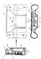
図3(a)は体脂肪計1の縦断面図、図3(b)は一部破断背面図、図3(c)は同横断面図である。
LCDパネル30等が取り付けられている基板31の裏面にセンサ32及びブザー25が取り付けられている。センサは図3のように基板に平行に配置されている場合に限らず、図4(a),(b),(c)に示すようにLCDパネルが取り付けられた基板に直交するセンサ基板33にセンサ32を取り付けるようにしてもよい。また、複数のセンサを異なる方向に配置してもよい。図3及び図4に示されているセンサ32上の矢印は、後述する可動電極の移動方向を示す。
【0028】
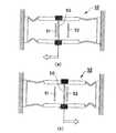
図5はセンサ32の概略構成を模式的に示す図である。
センサ32は、概略、弾性変形部41〜44を介してハウジング45に長手方向両端部を支持され、重り46,47が取り付けられた2本のビーム48,49と2本のビームの中央部に架設された可動電極50と可動電極50を挟む2つの固定電極51,52とからなる。センサ32に(図上)左方向加速度及び右方向加速度が加わった状態を図6(a),(b)にそれぞれ示す。まず、センサ32を含むセンサ部23が傾斜したり加速度を生じたりすると、その傾斜角度あるいはセンサ部23に生じる加速度の大きさに応じて重り46,47がセンサ部23内を移動する。弾性変形部41=44が弾性変形するので、重り46,47は2本のビーム48,49とともに移動し、可動電極50も移動する。可動電極50が移動すると2つの固定電極51,52と可動電極50との距離が変化する。センサ32では、単位時間当たりの静電容量変化から加速度を算出し、あるいは静電容量の値そのものから傾斜角度を算出する。センサ部23では、このようにしてセンサ32によって検出された加速度あるいは傾斜角度を、測定・演算制御部20に出力する。
【0029】
図7は、予め姿勢調整のための角度が設定されている場合の体脂肪計による測定手順を示すフローチャートである。
まず、電源スイッチがオンとなるのを待機する(ステップ1)。次に、身長,体重,年齢,性別等の身体特定化情報の各項目を入力し(ステップ2)、全項目が入力されるのを待機する(ステップ3)。設定スイッチ13によって各身体特定化情報の項目を選択し、加算スイッチ14又は減算スイッチ15によって数値を設定する。また、記録スイッチ11によって測定された体脂肪率等を記録することができ、個人データを加算スイッチ14等で選択した後に呼出スイッチ9によって記録された体脂肪率等のデータを表示することができる。また期間スイッチ10を押すことにより7日前等の過去の体脂肪率等のデータを表示し現在のデータと比較することができる。
【0030】
次に、センサ32によって体脂肪計1の本体の傾斜角度を検知し(ステップ4)、被検者の姿勢の調整を促す報知を行う(ステップ5)。体脂肪計1の現在の角度と設定角度とが一致するか否かを判定する(ステップ6)。体脂肪計1の現在の角度と設定角度が一致しない場合にはステップ5に戻り、一致する場合には測定を開始する(ステップ7)。測定終了を待って(ステップ8)、体脂肪率及び体脂肪量等の測定結果の表示を行う(ステップ9)。測定結果の表示から1分経過した後(ステップ10)、測定手順を終了する。
【0031】
ステップ7において、角度調整の完了によって自動的に測定を開始するようにしてもよいし、角度調整の完了後の測定開始スイッチ16又は18の押下によって測定を開始するようにしてもよい。
【0032】
上述の測定処理においては、体脂肪計1本体又はグリップ部2,3が水平に保たれた状態の角度が設定角度となっている。このように体脂肪計1本体又はグリップ部2,3が水平に保たれた状態でグリップ部2,3を握れば、電極部と掌との接触状態を常に一定に保持することができる。従って、測定姿勢が安定化し、測定精度を向上させることができる。姿勢調整のための設定角度は、上述のような水平の場合に限られず、適宜設定することもできる。
【0033】
図8は、被検者が自ら姿勢調整のための角度を設定する場合の測定手順を示すフローチャートである。
まず、電源スイッチ12がオンとなるのを待機する(ステップ11)。次に、身長,体重,年齢,性別等の身体特定化情報の各項目を入力し(ステップ12)、全項目が入力されるのを待機する(ステップ13)。
【0034】
次に、初めての測定であるか否か(すなわち測定記録が記憶されているか否か)を判定する(ステップ14)。
初めての測定である場合には、表示部8に正しい測定姿勢の説明を表示する(ステップ15)。このとき、「姿勢登録ボタンを押して、正しい測定姿勢をとってください。」との表示を行い、測定姿勢の設定方法を案内する(ステップ15)。
【0035】
次に、姿勢登録ボタン17の押下によって、体脂肪計1の角度計測を開始する(ステップ16,17)。姿勢調整状態の間はその旨を表示し(ステップ18)、正しい測定になるのを待つ(ステップ19)。正しい測定姿勢となったときに再び姿勢登録ボタン17を押下する(ステップ20)。
【0036】
姿勢登録ボタン17の押下に応答して押下時の姿勢情報(角度情報)を記録し(ステップ21)、ステップ23に進む。
ステップ14で測定記録がメモリされていれば、設定済みの姿勢情報を呼び出す(ステップ22)。
【0037】
次に、センサ32によって体脂肪計1の本体の傾斜角度の検知を行う(ステップ23)。傾斜角度の検知を行っている間に姿勢調整を促す旨の報知及び姿勢調整状態の表示を表示部8等において行う(ステップ24)。
【0038】
次に、体脂肪計1の現在の角度と設定角度とが一致するか否かを判定する(ステップ25)。体脂肪計1の現在の角度と設定角度が一致しない場合にはステップ24に戻り、一致する場合には測定を開始する(ステップ26)。
【0039】
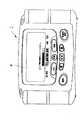
図9は、体脂肪計1の表示部8の姿勢調整状態における表示を示す。「正しい測定姿勢をとってください」とのメッセージを表示するとともに、バーを構成する全てのブロックが点灯するように測定姿勢を調整し、バーが全点灯した瞬間に親指近くの測定開始ボタン16,18を押して、測定を開始する。測定中はそのまま正しい測定姿勢を保っておく。図10も同様に体脂肪計1の表示部8の姿勢調整中の表示である。体脂肪計1本体の左右の傾きに応じて表示されるドットが左右に移動し、手前方向または奥方向の傾きに応じてドットが上下に移動する。ドットが円内に入るように姿勢を調整し、円内にドットが入っているときに自動的に測定が開始されるか又は測定開始ボタン16,18を押下することにより、測定を開始する。また、正しい測定姿勢になっていない場合はブザーが「ピッピッピッ」と鳴り続け、正しい測定姿勢になると「ピーッ」と鳴って報知するようにしてもよい。測定開始ボタン16,18を押した後に、「正しい測定姿勢をとって下さい。」と音声で報知し、正しい測定姿勢が実現されると「測定を開始します。そのままの姿勢で動かないで下さい。」と報知するようにしてもよい。
【0040】
測定終了を待って(ステップ27)、体脂肪率及び体脂肪量等の測定結果の表示を行う(ステップ28)。測定結果の表示から1分経過した後(ステップ29)、測定手順を終了する。
【0041】
このように被検者が正しい測定姿勢の範囲内で好みの測定姿勢を設定登録しておくことにより、次回の測定から被検者が設定された姿勢となるように調整するので、測定姿勢が安定化し、測定精度を向上させることができる。
【0042】
(第2の実施形態)
図11には、第2の実施形態に係る体脂肪計61が示されている。図11に示すように体脂肪計61は、グリップ部(保持部)62,基台部63及びこれらを接続するケーブル64からなる。略円柱形状のグリップ62部には軸方向に電流印加用電極65,電圧測定用電極66及びスイッチ67が設けられ、基台部63の表面には左右にそれぞれ電流印加用電極68,69と電圧測定用電極70,71とが配置されている。
【0043】
図12に示すように、被検者は一つのグリップ部62をいずれか一方の手で握り、基台部63上に載り、左右の足の裏をそれぞれ基台部63表面に設けられた電流印加用電極68,69及び電圧測定用電極70,71に接触させる。
【0044】
基台部63に設けられた4つの電極68〜71はそれぞれ電気的に独立している。グリップ部62及び基台部63の電極間の接続状態は切替可能であり、グリップ部62の電流印加用電極65及び電圧測定用電極66と、基台部63の左側又は右側の電流印加用電極68,69及び電圧測定用電極70,71のうちからいずれか一組(4つ)の電流印加用電極68(69)及び電圧測定用電極70(71)を選択することができる。選択された2つの電流印加用電極間に高周波電流を印加し、選択された電圧測定用電極によって印加電流による身体抵抗電位を測定することにより、異なる電流経路における身体インピーダンスの測定及び体脂肪率等の算出を行うことができるようになっている。ここでは、インピーダンス測定用電極は、電流印加用電極65,電圧測定用電極66並びに電流印加用電極68,69及び電圧測定用電極70,71から構成される。
【0045】
図13(a)はグリップ部62の側面図、図13(b)はグリップ部62の軸方向断面図である。体脂肪計 61のグリップ部62には基板72の裏面に基板72に平行に第1の実施形態で説明したセンサ32を取り付けている。このように構成することにより、本実施形態においても測定時の姿勢を安定化させ、測定精度の向上を図ることができる。
【0046】
(第3の実施形態)
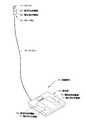
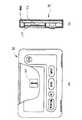
図14は本発明の第3の実施形態に係る歩数計付き体脂肪計81の全体構成を示す正面図である。図15(a)は歩数計部(歩数計数装置)82の全体構成を示す正面図、図15(b)は同側面図である。図16(a)は体脂肪計部83の全体構成を示す正面図、図16(b)は同平面図である。
【0047】
図15に示すように歩数計部82は扁平な略直方体のカード形状をなす。歩数計部82の前面の上方やや左寄りにLCDパネルの表示部84が設けられ、表示部84の下方及び右方にボタン類が配置されている。ボタン類としては、RESET/▲ボタン85、SETボタン86、MODEボタン87、INPUTボタン88、電源ONボタン89が設けられている。また、歩数計部82の底面の左右両端部には、SUS等の導電体からなる接点部90,91が設けられている。MODEボタン87によって時計→歩数→距離→カロリーの各表示を切り替える。SETボタン86によって時計・歩幅・体重の各項目を設定する。また、RESET▲ボタン85によって表示を「0」に戻しあるいは、時刻・歩幅・体重の数値の変更を行う。INPUTボタン88は積極的に歩行を行った場合に押して計測された歩数を記憶しておき、その後の日常生活における歩行については敢えて記憶しないようにしたり、MODEボタン87によって「歩行」か「走行」かを選択し、その上でカウントした分だけ記憶させることにより、「歩行」と「走行」の歩数を別々に積算したりすることができる。上記の各ボタンを用いて歩幅や体重を設定しておき、歩行やジョギングを行うことにより歩数をカウントするとともに距離や消費カロリーをも算出表示することができる。
【0048】
図16に示すように体脂肪計部83は2つの略円柱形状のグリップ部(保持部)101,102の間に板状の本体部103を配置した構造となっている。本体部103は、歩数計部82の形状に対応する形状にえぐられた凹部からなる装着部104を備える。装着部104の前面側104aは、歩数計部82の表示部84が前面側から視認できかつボタン類が操作できるように露出させ、装着された歩数計部82の前面の左右両縁及び下縁部分のみを保持するように上方に開口するコの字形状をなす。装着部104の背面側104bは、歩数計部82の背面を支持する板形状をなし、歩数計部を容易に取り出せるように中央上端部がU字状に切り欠かれている。装着部104の底面には、歩数計82底面の接点部90,91に対応する位置にSUSU等の導電体からなる2つの接点部105,106が設けられている。また、本体部103の前面の下方には、電源ボタン107、設定ボタン108、加算ボタン108、減算ボタン109、測定開始ボタン110が配置されている。グリップ部101,102の周面にはSUS等の導電体からなる電流印加用電極111,112及び電圧測定用電極113,114が軸方向に分割されて配置されている。また、左側のグリップ部101の上面には測定開始ボタン115が、右側のグリップ102部の上面には、姿勢登録ボタン116が配置されている。ここでは、インピーダンス測定用電極は、電流印加用電極111,112及び電圧測定用電極113,114から構成される。また、身体特定化情報入力手段は、設定ボタン108、加算ボタン108、減算ボタン109から構成される。
【0049】
図17に示されているように歩数計部82を表示部84側を前面にして体脂肪計部83の装着部104の凹部に上方から挿入して装着する。
図18は歩数計部82及び体脂肪計部83の内部構造の概略を示すブロック図である。
【0050】
歩数計部82は、測定,演算及び制御を行うCPU120に対してプログラムやデータ等を記憶するメモリ121,操作情報を入力する入力部122,センサ123からの情報に基づいて歩数をカウントする歩数カウンタ124,CPU120の指令に基づいて表示器125を駆動する表示器ドライバ126,体脂肪計部83との間を接続して情報の送受信を行う接点部90,91が接続された構成をなす。図19(a)は歩数計部82の一部を破断してセンサ123の配置状態を示した正面図であり、図19(b)は同断面図である。図19(a),(b)に示すようにセンサ123は基板127に平行に配置されている。センサ123は、被検者の歩行によって生じる加速度変化を検出する加速度センサであり、検出された加速度変化を歩数情報に変換している。センサ123は図5に示すものと同様の構成を有し、図19(a)上の矢印は可動電極の移動方向を示す。
【0051】
体脂肪計部83の構成は、センサを有しない点と歩数計部82との情報の送受信を行う接点部105,106を有する点を除いて第1の実施形態と同様の構成を有するので、同様の符号を用いて詳細な説明は省略する。ここで、CPU120又は測定・演算制御装置20が傾斜角度算出手段を構成する。
【0052】
歩数計部82は単体では歩数計として利用でき、体脂肪計部83に装着することにより体脂肪計として利用することができる。また、歩数計部82と体脂肪計部83との間でデータの送受信を行うことができる。歩数計部82を体脂肪計部83に装着し、体脂肪計として使用する場合には、測定姿勢を調整するためにセンサとして歩数計部82のセンサ123を利用することができる。このようなセンサ123を第1の実施形態における体脂肪計と同様に利用することにより、測定時の被検者の姿勢を安定化させ、測定精度を向上させることができる。
【0053】
図20(a),(b)に姿勢調整時の体脂肪計81を示す。姿勢調整の手順は第1の実施形態と同様であるが、本実施形態では歩数計部の表示部84に調整のための表示が行われる。
【0054】
図21は、歩数計部82の情報を体脂肪計部83に入力する場合の手順を示すフローチャートである。
まず、体脂肪計部から歩数計部を取り外すのを待機する(ステップ31)。
【0055】
歩数計部を体脂肪計部から取り外したところで歩数計の電源を自動的にONにする(ステップ32)。
次に、歩数の計数を開始する(ステップ33)。歩数計部を体脂肪計部から取り外したときから歩数の計数を開始するようにしてもよいし、被検者が身体に装着するまでの時間を考慮して取り外してから一定時間経過後に歩数の計数を開始するようにしてもよい。
【0056】
歩数の計数が終了するのを待って(ステップ34)、歩数計部を体脂肪計部に装着する(ステップ35)。
次に、体脂肪計部側のメモリエリアから対応する個人データを呼び出し(ステップ36)、表示部に表示する(ステップ37)。
【0057】
ここで、本人か否かを確認し(ステップ38)、本人でなければ個人データを再度入力する(ステップ39)。
ステップ9で、本人であれば、「設定ボタン」の押下によって(ステップ40)、歩数データが歩数計部側から体脂肪計部側のメモリエリアに転送される(ステップ41)。
【0058】
次に、体脂肪測定を行うか否かを判定する(ステップ42)。体脂肪測定を行う場合には、図7のステップ7〜10に示す体脂肪測定処理を行い(ステップ43)、電源をOFFして(ステップ44)、処理を終了する。体脂肪測定を行わない場合にはステップ44に進む。
【0059】
このように、歩数計部によって計数された歩数を体脂肪計に取り込むことによって消費カロリー等の情報を体脂肪率等の情報とともに蓄積し、継続的な健康管理に利用することができる。また、体脂肪率等から必要な運動量あるいは消費カロリーあるいは当該カロリーを消費するために必要な歩数を算出して、歩数計部に送信し、目標値の設定に利用することもできる。また、体脂肪率等の情報を歩数計部に転送してメモリに記憶させ、持ち歩く際に表示できるようにしておけば、常に体脂肪について意識し、ダイエット継続のきっかけとして利用することができる。
【0060】
体脂肪率等を測定する際に、算出に必要な身長,体重,年齢,性別等の身体特定化情報を入力するが、入力されたこれらのデータを歩数計部のメモリに記憶させておくようにしてもよい。歩数計部を個人がそれぞれ持ち歩き、複数の歩数計部を1台の体脂肪計部に装着して使用する場合に、個人データを歩数計部に保持しておくことにより、他人に見られることがなく、プライバシーを確保することができる。
【0061】
図19には明示していないが、体脂肪計部に装着されている時には歩数計部の電源を自動的にオフとし、あるいは体脂肪計部側の電源から充電できるようにしてもよい。
【0062】
また、本実施形態では、体脂肪計側にもCPU等を含む測定・演算制御部が設けられているが、歩数計部側にのみCPUを設け、測定・演算制御を歩数計部側のCPUで処理するようにしてもよい。
【0063】
【発明の効果】
以上説明したように、本発明によれば、健康管理指針アドバイス装置による測定時の姿勢を安定させることができるので、体脂肪率等の健康管理指針情報の測定精度を向上させることができる。
【図面の簡単な説明】
【図1】図1は本発明の第1の実施形態に係る体脂肪計の全体構成を示す外観図である。
【図2】図2は、本発明の第1の実施形態に係る体脂肪計の内部構成の概略を示すブロック図である。
【図3】図3(a)は本発明の第1の実施形態に係る体脂肪計の縦断面図、図3(b)は同一部破断背面図、図3(c)は同横断面図である。
【図4】図4(a)は本発明の第1の実施形態に係る体脂肪計の縦断面図、図4(b)は同一部破断背面図、図4(c)は同横断面図である。
【図5】図5はセンサの概略構成を模式的に示す図である。
【図6】図6(a)及び(b)はセンサに左方向加速度及び右方向加速度が加わった状態を示す図である。
【図7】図7は予め姿勢調整のための角度が設定されている場合の体脂肪計による測定手順を示すフローチャートである。
【図8】図8は被検者が自ら姿勢調整のための角度を設定する場合の測定手順を示すフローチャートである。
【図9】図9は体脂肪計の表示部の姿勢調整状態における表示を示す図である。
【図10】図10は体脂肪計の表示部の姿勢調整状態における表示を示す図である。
【図11】図11は本発明の第2の実施形態にかかる体脂肪計の全体構成を示す斜視図である。
【図12】図12は被検者が体脂肪計を使用する状態を示す図である。
【図13】図13(a)はグリップ部の側面図、図13(b)はグリップ部の軸方向断面図である。
【図14】図14は本発明の第3の実施形態に係る歩数計付き体脂肪計の全体構成を示す正面図である。
【図15】図15(a)は歩数計部の全体構成を示す正面図、図15(b)は同側面図である。
【図16】図16(a)は体脂肪計部の全体構成を示す正面図、図16(b)は同平面図である。
【図17】図17は歩数計部を体脂肪計部に装着する方法を説明する図である。
【図18】図18は歩数計部及び体脂肪計部の内部構造の概略を示すブロック図である。
【図19】図19(a)は歩数計部の一部を破断してセンサの配置状態を示した正面図であり、図19(b)は同断面図である。
【図20】図20(a),(b)は姿勢調整時の体脂肪計を示す図である。
【図21】図21は歩数計部の情報を体脂肪計部に入力する場合の手順を示すフローチャートである。
【図22】図22は従来の体脂肪計の使用時の姿勢を示す図である。
【図23】図23は従来の体脂肪計のグリップ部の握り方の例を示す図である。
【図24】図24は従来の体脂肪計のグリップ部の握り方の例を示す図である。
【符号の説明】
1,61,81 体脂肪計
2,3,62 グリップ部
4,5,65,111,112 電流印加用電極
6,7,66,113,114 電圧測定用電極
17,116 姿勢登録ボタン
32,123 センサ[0001]
BACKGROUND OF THE INVENTION
The present invention relates to a health management guideline advice device such as a body fat scale that provides guideline information useful for health management such as body fat percentage based on impedance measurement.
[0002]
[Prior art]
Conventionally, as this type of health management guideline advice device, there has been a body fat scale that is measured by a subject by hand, such as a body fat scale 201 provided with an electrode for impedance measurement in a grip portion.
[0003]
[Problems to be solved by the invention]
However, in the case of the prior art as described above, as shown in FIG. 22, the
[0004]
Further, even if the arms are straight and forward as shown in FIG. 22, if the thumb is extended in the axial direction of the
[0005]
If the posture of the subject at the time of measurement changes in this way, there is a possibility that the measurement value may be affected.Therefore, when measuring body fat continuously for a long time for the purpose of dieting, it must be surely fixed. It was desired to be able to measure with posture.
[0006]
The present invention has been made to solve the above-described problems of the prior art, and the object of the present invention is to stabilize the measurement posture so that the subject always has the same posture at the time of measurement. It is to provide a high health management guideline advice device.
[0007]
[Means for Solving the Problems]
In order to achieve the above object, the present invention includes a holding unit that is held by at least one of the hands, and an impedance measurement electrode. The impedance measurement electrode is provided in the holding unit, and the measured impedance is obtained. A health management guideline advice device that provides guideline information useful for health management based on an angle detection unit that detects an inclination angle of the held portion.
[0008]
The holding unit may be provided separately from the main body of the health management guideline advice device.
[0009]
Moreover, you may make it provide the memory | storage means to memorize | store the angle detected by the said angle detection means.
[0010]
In addition, an angle comparison unit that compares an angle detected by the angle detection unit with an angle stored in the storage unit, and a notification unit that notifies a comparison result by the angle comparison unit may be provided.
[0011]
Further, the notification means may be a notification means by voice.
[0012]
Further, the notifying means may be means for visually displaying and notifying information.
[0013]
Further, an acquisition instruction unit that instructs acquisition of angle information of the holding unit to be stored in the storage unit may be arranged at or near the position of the hand in a predetermined holding posture.
[0014]
Further, an angle comparison unit that compares an angle detected by the angle detection unit with an angle stored in the storage unit may be provided, and impedance measurement may be started based on a comparison result by the angle comparison unit.
[0015]
The present invention includes a weight counting device that includes a weight and counts the number of steps based on a moving amount of the weight, and a mounting portion to which the step counting device is detachably mounted, and the step counting device is installed in the mounting portion. In the mounted state, the inclination angle detecting means for calculating the inclination angle of the holding unit based on the movement amount of the weight built in the step counting apparatus is at least one of the step counting apparatus and the health management guideline advice apparatus main body. Health management guideline advice device provided in
[0016]
The calculation of the inclination angle of the holding unit may be performed in the step counting device, or may be performed in the health management guideline advice device main body while being mounted on the mounting unit.
[0017]
Further, the step counting device may be provided with processing means for performing at least one of processing from impedance measurement to provision of guide information useful for health care.
[0018]
Moreover, you may make it provide the angle comparison means which compares the angle of the said holding | maintenance part with a predetermined angle.
[0019]
Moreover, you may make it provide the alerting | reporting means which alert | reports the comparison result by the said angle comparison means.
[0020]
Further, the notification means may be a notification means by voice.
[0021]
Further, the notifying means may be means for visually displaying and notifying information.
[0022]
The body specifying information input means for inputting the body specifying information for specifying the physical characteristics of the subject and the body specifying information holding means for holding the input body specifying information, the body specifying A digitization information holding means may be provided in the step counting device.
[0023]
DETAILED DESCRIPTION OF THE INVENTION
Hereinafter, preferred embodiments of the present invention will be described with reference to the drawings.
(First embodiment)
FIG. 1 is an external view showing an overall configuration of a body fat scale according to the first embodiment of the present invention.
[0024]
The housing of the
[0025]
FIG. 2 is a block diagram showing an outline of the internal configuration of the body fat scale.
A
[0026]
In the
[0027]
3A is a longitudinal sectional view of the
The
[0028]
FIG. 5 is a diagram schematically showing a schematic configuration of the
The
[0029]
FIG. 7 is a flowchart showing a measurement procedure using a body fat scale when an angle for posture adjustment is set in advance.
First, it waits for the power switch to be turned on (step 1). Next, each item of body specifying information such as height, weight, age, and sex is input (step 2), and it waits for all items to be input (step 3). Each setting item is selected by the setting switch 13, and a numerical value is set by the addition switch 14 or the
[0030]
Next, the inclination angle of the main body of the
[0031]
In
[0032]
In the measurement process described above, the angle in a state where the
[0033]
FIG. 8 is a flowchart showing the measurement procedure when the subject himself / herself sets an angle for posture adjustment.
First, it waits for the power switch 12 to be turned on (step 11). Next, each item of body specifying information such as height, weight, age, and sex is input (step 12), and it waits for all items to be input (step 13).
[0034]
Next, it is determined whether or not it is the first measurement (that is, whether or not a measurement record is stored) (step 14).
If it is the first measurement, a description of the correct measurement posture is displayed on the display unit 8 (step 15). At this time, the message “Press the posture registration button to take the correct measurement posture” is displayed, and the method for setting the measurement posture is guided (step 15).
[0035]
Next, angle measurement of the
[0036]
In response to the pressing of the
If the measurement record is stored in step 14, the set posture information is called (step 22).
[0037]
Next, the
[0038]
Next, it is determined whether or not the current angle of the
[0039]
FIG. 9 shows a display in the posture adjustment state of the
[0040]
Waiting for the end of measurement (step 27), measurement results such as body fat percentage and body fat amount are displayed (step 28). After 1 minute has elapsed from the display of the measurement result (step 29), the measurement procedure is terminated.
[0041]
In this way, the subject is set and registered with his / her preferred measurement posture within the range of the correct measurement posture, so that the subject is adjusted so that the posture is set from the next measurement. Stabilization and measurement accuracy can be improved.
[0042]
(Second Embodiment)
FIG. 11 shows a body fat scale 61 according to the second embodiment. As shown in FIG. 11, the body fat scale 61 includes a grip part (holding part) 62, a
[0043]
As shown in FIG. 12, the subject holds one
[0044]
The four electrodes 68 to 71 provided on the
[0045]
FIG. 13A is a side view of the
[0046]
(Third embodiment)
FIG. 14 is a front view showing the overall configuration of a
[0047]
As shown in FIG. 15, the
[0048]
As shown in FIG. 16, the body
[0049]
As shown in FIG. 17, the
FIG. 18 is a block diagram showing an outline of the internal structure of the
[0050]
The
[0051]
Since the configuration of the body
[0052]
The
[0053]
FIGS. 20A and 20B show a
[0054]
FIG. 21 is a flowchart showing a procedure for inputting information from the
First, it waits to remove the pedometer from the body fat meter (step 31).
[0055]
When the pedometer is removed from the body fat scale, the pedometer is automatically turned on (step 32).
Next, the step count is started (step 33). It may be possible to start counting the number of steps from the time when the pedometer unit is removed from the body fat meter unit, or the number of steps after a certain period of time has elapsed after removing the pedometer in consideration of the time until the subject wears on the body. The counting may be started.
[0056]
Waiting for the counting of the number of steps to be completed (step 34), the pedometer is attached to the body fat meter (step 35).
Next, the corresponding personal data is called from the memory area on the body fat scale unit side (step 36) and displayed on the display unit (step 37).
[0057]
Here, it is confirmed whether or not the person is the person (step 38). If the person is not the person, the personal data is input again (step 39).
In
[0058]
Next, it is determined whether or not to perform body fat measurement (step 42). When performing body fat measurement, the body fat measurement process shown in
[0059]
In this way, by taking the number of steps counted by the pedometer unit into the body fat scale, information such as calorie consumption can be accumulated together with information such as body fat percentage, and can be used for continuous health management. It is also possible to calculate the amount of exercise required, calorie consumption or the number of steps required to consume the calorie from the body fat percentage, etc., and send it to the pedometer unit for use in setting the target value. In addition, if information such as body fat percentage is transferred to the pedometer and stored in the memory so that it can be displayed when carried, it can be always conscious of body fat and used as an opportunity to continue dieting.
[0060]
When measuring body fat percentage, etc., body specific information such as height, weight, age, sex, etc. necessary for calculation is input, but these input data are stored in the memory of the pedometer unit. It may be. When individuals carry their own pedometer units and use multiple pedometer units attached to a single body fat meter unit, they can be seen by others by holding personal data in the pedometer unit There is no, and privacy can be secured.
[0061]
Although not explicitly shown in FIG. 19, the pedometer unit may be automatically turned off when it is attached to the body fat scale unit, or may be charged from the power source on the body fat scale unit side.
[0062]
In the present embodiment, the measurement / calculation control unit including a CPU or the like is also provided on the body fat meter side, but the CPU is provided only on the pedometer unit side, and the measurement / calculation control is performed on the CPU on the pedometer unit side. You may make it process by.
[0063]
【The invention's effect】
As described above, according to the present invention, the posture at the time of measurement by the health management guideline advice device can be stabilized, so that the measurement accuracy of health management guideline information such as body fat percentage can be improved.
[Brief description of the drawings]
FIG. 1 is an external view showing an overall configuration of a body fat scale according to a first embodiment of the present invention.
FIG. 2 is a block diagram showing an outline of the internal configuration of the body fat scale according to the first embodiment of the present invention.
FIG. 3 (a) is a longitudinal sectional view of a body fat scale according to the first embodiment of the present invention, FIG. 3 (b) is a rear sectional view of the same part, and FIG. 3 (c) is a transverse sectional view thereof. It is.
4 (a) is a longitudinal sectional view of a body fat scale according to the first embodiment of the present invention, FIG. 4 (b) is a rear sectional view of the same part, and FIG. 4 (c) is a transverse sectional view thereof. It is.
FIG. 5 is a diagram schematically illustrating a schematic configuration of a sensor.
FIGS. 6A and 6B are diagrams showing a state in which leftward acceleration and rightward acceleration are applied to the sensor.
FIG. 7 is a flowchart showing a measurement procedure using a body fat scale when an angle for posture adjustment is set in advance.
FIG. 8 is a flowchart showing a measurement procedure when the subject himself / herself sets an angle for posture adjustment.
FIG. 9 is a diagram showing a display in the posture adjustment state of the display unit of the body fat scale.
FIG. 10 is a diagram showing a display in the posture adjustment state of the display unit of the body fat scale.
FIG. 11 is a perspective view showing an overall configuration of a body fat scale according to a second embodiment of the present invention.
FIG. 12 is a view showing a state in which a subject uses a body fat scale.
13A is a side view of the grip portion, and FIG. 13B is an axial sectional view of the grip portion.
FIG. 14 is a front view showing an overall configuration of a body fat scale with a pedometer according to a third embodiment of the present invention.
FIG. 15 (a) is a front view showing the overall configuration of the pedometer, and FIG. 15 (b) is a side view thereof.
FIG. 16 (a) is a front view showing the entire configuration of the body fat scale unit, and FIG. 16 (b) is a plan view of the same.
FIG. 17 is a diagram for explaining a method of attaching the pedometer unit to the body fat meter unit.
FIG. 18 is a block diagram showing an outline of the internal structure of a pedometer unit and a body fat meter unit.
FIG. 19 (a) is a front view showing a sensor arrangement state with a part of the pedometer section broken, and FIG. 19 (b) is a cross-sectional view thereof.
20 (a) and 20 (b) are views showing a body fat scale at the time of posture adjustment.
FIG. 21 is a flowchart showing a procedure for inputting information from the pedometer unit to the body fat meter unit.
FIG. 22 is a view showing a posture during use of a conventional body fat scale.
FIG. 23 is a diagram showing an example of how to grip a grip portion of a conventional body fat scale.
FIG. 24 is a diagram showing an example of how to grip a grip portion of a conventional body fat scale.
[Explanation of symbols]
1,61,81 Body fat scale
2, 3, 62 Grip part
4,5,65,111,112 Current application electrode
6, 7, 66, 113, 114 Voltage measurement electrode
17,116 Posture registration button
32,123 sensors
Claims (15)
Translated fromJapaneseインピーダンス測定用電極を備え、
いずれかのインピーダンス測定用電極を前記保持部に設け、
測定されたインピーダンスに基づいて健康管理に有益な指針情報を提供する健康管理指針アドバイス装置であって、
保持された前記保持部の傾斜角度を検出する角度検出手段を備えた健康管理指針アドバイス装置。A holding part that is held by at least one of the hands;
It has an electrode for impedance measurement,
Any one electrode for impedance measurement is provided in the holding part,
A health care guideline advice device that provides useful guideline information for health care based on measured impedance,
A health management guideline advice device comprising angle detection means for detecting an inclination angle of the held portion.
前記角度比較手段による比較結果を報知する報知手段を備えた請求項3記載の健康管理指針アドバイス装置。An angle comparison means for comparing the angle detected by the angle detection means with the angle stored in the storage means;
The health management guideline advice device according to claim 3, further comprising notification means for notifying a comparison result by the angle comparison means.
前記角度比較手段による比較結果に基づいてインピーダンス測定を開始する請求項3記載の健康管理指針アドバイス装置。An angle comparison means for comparing the angle detected by the angle detection means with the angle stored in the storage means;
The health management guideline advice device according to claim 3, wherein impedance measurement is started based on a comparison result by the angle comparison means.
インピーダンス測定用電極を備え、
いずれかのインピーダンス測定用電極を前記保持部に設け、
測定されたインピーダンスに基づいて健康管理に有益な指針情報を提供する健康管理指針アドバイス装置であって、
重りを内蔵し、重りの移動量に基づいて歩数を計数する歩数計数装置と、
前記歩数計数装置が着脱可能に装着される装着部を備え、
前記装着部に前記歩数計数装置が装着された状態で、前記歩数計数装置に内蔵された重りの移動量に基づいて前記保持部の傾斜角度を算出する傾斜角度検出手段を前記歩数計数装置及び健康管理指針アドバイス装置本体の少なくともいずれかに設けた健康管理指針アドバイス装置。A holding part that is held by at least one of the hands;
It has an electrode for impedance measurement,
Any one electrode for impedance measurement is provided in the holding part,
A health care guideline advice device that provides useful guideline information for health care based on measured impedance,
A step counting device that incorporates a weight and counts the number of steps based on the amount of movement of the weight;
A mounting portion on which the step counting device is detachably mounted;
An inclination angle detecting means for calculating an inclination angle of the holding unit based on a movement amount of a weight built in the step counting device in a state where the step counting device is mounted on the mounting unit. A health management guideline advice device provided in at least one of the management guideline advice devices.
前記入力された身体特定化情報を保持する身体特定化情報保持手段を備え、
前記身体特定化情報保持手段を前記歩数計数装置に設けた請求項9乃至14のいずれかに記載の健康管理指針アドバイス装置。Body specifying information input means for inputting body specifying information for specifying the physical characteristics of the subject;
Comprising body specifying information holding means for holding the inputted body specifying information;
The health management guideline advice device according to any one of claims 9 to 14, wherein the body specifying information holding means is provided in the step counting device.
Priority Applications (1)
| Application Number | Priority Date | Filing Date | Title |
|---|---|---|---|
| JP34149099AJP3772617B2 (en) | 1999-11-30 | 1999-11-30 | Health care guideline advice device |
Applications Claiming Priority (1)
| Application Number | Priority Date | Filing Date | Title |
|---|---|---|---|
| JP34149099AJP3772617B2 (en) | 1999-11-30 | 1999-11-30 | Health care guideline advice device |
Publications (2)
| Publication Number | Publication Date |
|---|---|
| JP2001149328A JP2001149328A (en) | 2001-06-05 |
| JP3772617B2true JP3772617B2 (en) | 2006-05-10 |
Family
ID=18346467
Family Applications (1)
| Application Number | Title | Priority Date | Filing Date |
|---|---|---|---|
| JP34149099AExpired - Fee RelatedJP3772617B2 (en) | 1999-11-30 | 1999-11-30 | Health care guideline advice device |
Country Status (1)
| Country | Link |
|---|---|
| JP (1) | JP3772617B2 (en) |
Families Citing this family (11)
| Publication number | Priority date | Publication date | Assignee | Title |
|---|---|---|---|---|
| JP4155889B2 (en)* | 2003-07-14 | 2008-09-24 | ホシデン株式会社 | Body motion detection device |
| JP2004041819A (en)* | 2003-11-26 | 2004-02-12 | Ya Man Ltd | Adipometer |
| JP2005211196A (en)* | 2004-01-28 | 2005-08-11 | Matsushita Electric Ind Co Ltd | Biological information measuring device |
| JP2006239237A (en)* | 2005-03-04 | 2006-09-14 | Tanita Corp | Biometric device |
| JP4830765B2 (en)* | 2006-09-29 | 2011-12-07 | パナソニック電工株式会社 | Activity measurement system |
| JP5493198B2 (en)* | 2007-08-25 | 2014-05-14 | 株式会社タニタ | Biometric data measuring instrument |
| JP5163197B2 (en) | 2008-03-14 | 2013-03-13 | オムロンヘルスケア株式会社 | Posture evaluation device |
| JP5340644B2 (en)* | 2008-06-04 | 2013-11-13 | 株式会社タニタ | Abdominal circumference measuring device |
| JP2016097237A (en)* | 2014-11-26 | 2016-05-30 | 株式会社デンソー | Biomedical signal detection apparatus |
| JP7233692B2 (en)* | 2019-03-29 | 2023-03-07 | 株式会社タニタ | BIOLOGICAL DATA MEASURING DEVICE, BIOLOGICAL DATA MEASURING METHOD, AND PROGRAM |
| JP7273407B2 (en)* | 2019-06-26 | 2023-05-15 | 株式会社タニタ | activity meter |
- 1999
- 1999-11-30JPJP34149099Apatent/JP3772617B2/ennot_activeExpired - Fee Related
Also Published As
| Publication number | Publication date |
|---|---|
| JP2001149328A (en) | 2001-06-05 |
Similar Documents
| Publication | Publication Date | Title |
|---|---|---|
| CN107693020B (en) | Spinal physiological curvature monitoring device and spinal physiological curvature monitoring method | |
| EP1166716B1 (en) | Bioelectrical impedance measuring apparatus | |
| EP0998875B1 (en) | Body fat meter with stature measuring instrument | |
| JP3772617B2 (en) | Health care guideline advice device | |
| US6360124B1 (en) | Handheld bioelectric impedance measuring apparatus | |
| JP2002345774A5 (en) | ||
| EP1095614B1 (en) | Dividable type apparatus for measuring living body impedance | |
| WO2015063765A1 (en) | Walker-assist device | |
| JP2001161670A (en) | Calculator for calorie | |
| JP2001276012A (en) | Portable instrument for measuring biological electric impedance | |
| JP2020163015A (en) | Biometric data measuring device, biometric data measuring method and program | |
| JP2004081621A (en) | Physique and physical strength determination method and physique and physical strength determination device | |
| EP1092388B1 (en) | Body composition measuring apparatus with built-in weight meter | |
| JP5470575B2 (en) | Exercise state measuring apparatus and biometric apparatus | |
| JP3795363B2 (en) | Basal metabolism measuring device | |
| JP4369855B2 (en) | Flexible exercise equipment | |
| JP2001078978A (en) | Health management guide advice device | |
| JP2001252258A (en) | Adipose display controller and stature display controller | |
| JP2003159227A (en) | Apparatus for advising guide to health care | |
| JP2003070762A (en) | Health management index advising device | |
| JP2001012997A (en) | Scale | |
| JPH11299752A (en) | Body fat meter | |
| JP4069500B2 (en) | Body fat measuring device | |
| KR20060028230A (en) | Body composition measuring instrument and measuring method | |
| JP4686308B2 (en) | Lower limb training device |
Legal Events
| Date | Code | Title | Description |
|---|---|---|---|
| A977 | Report on retrieval | Free format text:JAPANESE INTERMEDIATE CODE: A971007 Effective date:20050117 | |
| TRDD | Decision of grant or rejection written | ||
| A01 | Written decision to grant a patent or to grant a registration (utility model) | Free format text:JAPANESE INTERMEDIATE CODE: A01 Effective date:20060124 | |
| A61 | First payment of annual fees (during grant procedure) | Free format text:JAPANESE INTERMEDIATE CODE: A61 Effective date:20060206 | |
| R150 | Certificate of patent or registration of utility model | Free format text:JAPANESE INTERMEDIATE CODE: R150 | |
| FPAY | Renewal fee payment (event date is renewal date of database) | Free format text:PAYMENT UNTIL: 20100224 Year of fee payment:4 | |
| FPAY | Renewal fee payment (event date is renewal date of database) | Free format text:PAYMENT UNTIL: 20110224 Year of fee payment:5 | |
| FPAY | Renewal fee payment (event date is renewal date of database) | Free format text:PAYMENT UNTIL: 20110224 Year of fee payment:5 | |
| FPAY | Renewal fee payment (event date is renewal date of database) | Free format text:PAYMENT UNTIL: 20120224 Year of fee payment:6 | |
| FPAY | Renewal fee payment (event date is renewal date of database) | Free format text:PAYMENT UNTIL: 20120224 Year of fee payment:6 | |
| FPAY | Renewal fee payment (event date is renewal date of database) | Free format text:PAYMENT UNTIL: 20130224 Year of fee payment:7 | |
| FPAY | Renewal fee payment (event date is renewal date of database) | Free format text:PAYMENT UNTIL: 20140224 Year of fee payment:8 | |
| LAPS | Cancellation because of no payment of annual fees |