JP3771252B1 - Dot pattern - Google Patents
Dot patternDownload PDFInfo
- Publication number
- JP3771252B1 JP3771252B1JP2005194295AJP2005194295AJP3771252B1JP 3771252 B1JP3771252 B1JP 3771252B1JP 2005194295 AJP2005194295 AJP 2005194295AJP 2005194295 AJP2005194295 AJP 2005194295AJP 3771252 B1JP3771252 B1JP 3771252B1
- Authority
- JP
- Japan
- Prior art keywords
- dot
- information
- block
- dots
- virtual
- Prior art date
- Legal status (The legal status is an assumption and is not a legal conclusion. Google has not performed a legal analysis and makes no representation as to the accuracy of the status listed.)
- Expired - Lifetime
Links
Images


Classifications
- G—PHYSICS
- G06—COMPUTING OR CALCULATING; COUNTING
- G06K—GRAPHICAL DATA READING; PRESENTATION OF DATA; RECORD CARRIERS; HANDLING RECORD CARRIERS
- G06K19/00—Record carriers for use with machines and with at least a part designed to carry digital markings
- G06K19/06—Record carriers for use with machines and with at least a part designed to carry digital markings characterised by the kind of the digital marking, e.g. shape, nature, code
- G06K19/06009—Record carriers for use with machines and with at least a part designed to carry digital markings characterised by the kind of the digital marking, e.g. shape, nature, code with optically detectable marking
- G06K19/06037—Record carriers for use with machines and with at least a part designed to carry digital markings characterised by the kind of the digital marking, e.g. shape, nature, code with optically detectable marking multi-dimensional coding
- G—PHYSICS
- G06—COMPUTING OR CALCULATING; COUNTING
- G06F—ELECTRIC DIGITAL DATA PROCESSING
- G06F3/00—Input arrangements for transferring data to be processed into a form capable of being handled by the computer; Output arrangements for transferring data from processing unit to output unit, e.g. interface arrangements
- G06F3/01—Input arrangements or combined input and output arrangements for interaction between user and computer
- G06F3/03—Arrangements for converting the position or the displacement of a member into a coded form
- G06F3/033—Pointing devices displaced or positioned by the user, e.g. mice, trackballs, pens or joysticks; Accessories therefor
- G06F3/0354—Pointing devices displaced or positioned by the user, e.g. mice, trackballs, pens or joysticks; Accessories therefor with detection of 2D relative movements between the device, or an operating part thereof, and a plane or surface, e.g. 2D mice, trackballs, pens or pucks
- G06F3/03545—Pens or stylus
- G—PHYSICS
- G06—COMPUTING OR CALCULATING; COUNTING
- G06K—GRAPHICAL DATA READING; PRESENTATION OF DATA; RECORD CARRIERS; HANDLING RECORD CARRIERS
- G06K19/00—Record carriers for use with machines and with at least a part designed to carry digital markings
- G06K19/06—Record carriers for use with machines and with at least a part designed to carry digital markings characterised by the kind of the digital marking, e.g. shape, nature, code
- G—PHYSICS
- G06—COMPUTING OR CALCULATING; COUNTING
- G06K—GRAPHICAL DATA READING; PRESENTATION OF DATA; RECORD CARRIERS; HANDLING RECORD CARRIERS
- G06K7/00—Methods or arrangements for sensing record carriers, e.g. for reading patterns
- G06K7/10—Methods or arrangements for sensing record carriers, e.g. for reading patterns by electromagnetic radiation, e.g. optical sensing; by corpuscular radiation
Landscapes
- Engineering & Computer Science (AREA)
- Theoretical Computer Science (AREA)
- Physics & Mathematics (AREA)
- General Physics & Mathematics (AREA)
- General Engineering & Computer Science (AREA)
- Human Computer Interaction (AREA)
- General Health & Medical Sciences (AREA)
- Electromagnetism (AREA)
- Health & Medical Sciences (AREA)
- Toxicology (AREA)
- Artificial Intelligence (AREA)
- Computer Vision & Pattern Recognition (AREA)
- Image Processing (AREA)
- Editing Of Facsimile Originals (AREA)
- Image Analysis (AREA)
- Processing Or Creating Images (AREA)
Abstract
Translated fromJapaneseDescription
Translated fromJapanese本発明は、印刷物等に形成したドットパターン情報を光学的に読み取ることにより、様々な情報やプログラムを入出力させるドットパターンを用いた情報入出力方法に関するものであり、特にドットで構成されるブロックの向きを判定できる技術に関する。 The present invention relates to an information input / output method using a dot pattern for inputting / outputting various information and programs by optically reading dot pattern information formed on a printed material or the like, and in particular, a block composed of dots. It is related with the technique which can judge the direction of the.
従来より、印刷物等に印刷されたバーコードを読み取り、音声等の情報を出力させる情報出力方法が提案されている。たとえば、あらかじめ記憶手段に与えられたキー情報に一致する情報を記憶させておき、バーコードリーダで読み込まれたキーから検索して情報等を出力する方法が提案されている。 また、多くの情報やプログラムを出力できるように、微細なドットを所定の法則で並べたドットパターンを生成し、印刷物等に印刷したドットパターンをカメラにより画像データとして取り込み、デジタル化して音声情報を出力させる技術も提案されている。 Conventionally, an information output method for reading a barcode printed on a printed matter and outputting information such as voice has been proposed. For example, a method has been proposed in which information matching key information given in advance to a storage means is stored, information is retrieved by searching from a key read by a bar code reader. In addition, a dot pattern in which fine dots are arranged according to a predetermined rule is generated so that a large amount of information and programs can be output, and the dot pattern printed on a printed material is captured as image data by a camera and digitized to obtain audio information. A technique for outputting is also proposed.
しかし、上記従来のバーコードにより音声等を出力させる方法は、印刷物等に印刷されたバーコードが目障りであるという問題を有していた。また、バーコードが大きく、紙面の一部を占有するため、このようにバーコードが大きいと、一部分の文章やセンテンスまたは、写真、絵、グラフィックの画像の中に登場する意味を有するキャラクターや対象物毎に分り易く数多くのバーコードを割り当てることはレイアウト上不可能であるという問題を有していた。 However, the conventional method of outputting sound or the like using the barcode has a problem that the barcode printed on the printed matter is annoying. In addition, since the barcode is large and occupies a part of the paper surface, if the barcode is large in this way, characters and objects that have the meaning of appearing in a part of text or sentence, or in a picture, picture, or graphic image There is a problem in that it is difficult to assign a large number of barcodes for each object because of the layout.
そこで、本発明者は、下記の特許文献に示すように、印刷面に影響を与えることなく多くのデータを格納できる全く新しいドットパターンを提案してきている。
これらの本発明者による先行技術(特許文献1、2)において、本発明者はキードットを設けてデータの方向(ブロックの方向)とブロックの領域を定義することを提案している。このようにブロックの方向が把握できることにより、ブロックで定義された情報をその方向毎に異なる意味とすることができるため、多様な情報を格納できるという本発明者独自の独創的なドットパターンを提案している。 In these prior arts (
しかし、このキードットによりブロックの方向を定義する技術は、キードットを配置するための箇所には情報ドットが配置できないために、ブロックの情報量が制限されることになり、かつ、キードットを探索するためのアルゴリズムが複雑化して計算時間を要し、かつキードットの周辺領域の着目量が大きいため、フレームバッファの解像度も必要であるという克服すべき課題のあることが本発明者によって新たに指摘された。 However, the technology for defining the direction of the block with this key dot limits the amount of information in the block because the information dot cannot be placed at the location where the key dot is placed, and the key dot The inventor newly found that there is a problem to be overcome that the algorithm for searching is complicated and requires calculation time, and because the amount of attention in the peripheral area of the key dot is large, the resolution of the frame buffer is also necessary. Pointed out.
本発明は、このような点に鑑みてなされたもので、ブロックの方向を定義するために情報ドットを犠牲にすることなく、その探索のアルゴリズムが簡易でかつ低解像度のフレームバッファでも読み取りが可能な、キードットに代わるディレクションドットの技術を実現することを課題とする。 The present invention has been made in view of these points, and the search algorithm is simple and can be read by a low-resolution frame buffer without sacrificing information dots to define the direction of the block. The challenge is to realize direction dot technology to replace key dots.
前記課題を解決するために、本発明では、以下の手段を採用した。 In order to solve the above problems, the present invention employs the following means.
すなわち、本発明の請求項1は、所定の情報ドットを配置するブロックの領域内に複数の基準点を設け、該基準点から定義される複数の仮想基準点(たとえば格子領域の中心点)を配置し、前記仮想基準点からの距離と方向とで情報が定義される情報ドットを配置し、前記少なくとも所定の位置の情報ドットを、前記仮想基準点からの方向で前記ブロックの向きを示すディレクションドットとしたドットパターンである。 That is, according to
すなわち、本発明では、紙面等の媒体面上に所定の規則(たとえば三角形や四角形さらにはそれ以上の多角形の頂点や、それらの辺の所定間隔毎等)に基づいて基準点を配置する。そしてその配置された複数の基準点からある規則に基づいて仮想基準点を設定する。ここである規則とは、たとえば、前記多角形の頂点同士を結んだ線の交点を仮想基準点とするような場合である。そして、この仮想基準点を始点にしたベクトルの終点にドットを配置する。このドットは情報を定義する情報ドットとして機能するが、少なくともブロック中の1つの情報ドットの向きを他とは異なるものとすることによって当該ブロックの向きや大きさを示すディレクションドットとすることができる。ここで向きとは当該ディレクションドットが前記仮想基準点から上方向のベクトル終点に配置されている場合には、このディレクションドットが所属するブロックは上向きであることが識別できる。 That is, in the present invention, the reference points are arranged on a medium surface such as a paper surface based on a predetermined rule (for example, a vertex of a triangle, a quadrangle or more polygons, or a predetermined interval between these sides). A virtual reference point is set based on a certain rule from the plurality of reference points arranged. The rule here is, for example, a case where an intersection of lines connecting the vertices of the polygon is used as a virtual reference point. Then, a dot is arranged at the end point of the vector starting from this virtual reference point. This dot functions as an information dot that defines information, but at least one information dot in a block can be a direction dot that indicates the direction and size of the block by making the direction different from the others. . Here, when the direction dot is arranged at the vector end point upward from the virtual reference point, it can be identified that the block to which the direction dot belongs is upward.
また、大きさについては、複数のブロックが連結されている場合に、前記ディレクションドットの配置位置の繰り返しパターンによってブロックの大きさが識別できる。たとえば、ディレクションドットがブロック中心に配置されている場合、当該ディレクションドットが上下左右方向に3格子領域毎に現れていれば、当該ブロックは3×3格子領域の大きさを有することが識別できる。 As for the size, when a plurality of blocks are connected, the size of the block can be identified by a repetitive pattern of the direction dot arrangement positions. For example, when the direction dot is arranged at the center of the block, if the direction dot appears in every three grid areas in the vertical and horizontal directions, it can be identified that the block has a size of 3 × 3 grid area.
このように、情報ドットをブロックの向きを示すディレクションドットと兼用することによって、このディレクションドット自体にも情報を意味づけつつ、ブロックの方向を定義することができるため、情報ドットを犠牲にすることなく、ブロックの向きを定義することができる。 In this way, by combining the information dot with the direction dot that indicates the direction of the block, the direction of the block can be defined while meaning the information in the direction dot itself, so the information dot is sacrificed. Without defining the direction of the block.
また、このようなブロック内のディレクションドットを配置する矩形領域を、いずれかの基準点を中心に90度ずつ回転させたとき、すなわち、90度、180度、270度回転させたときに同一の位置関係が再現されることのないように配置することで、探索のアルゴリズムが簡易でかつ低解像度のフレームバッファでも読み取りが可能となる。 In addition, when the rectangular area in which the direction dots in such a block are arranged is rotated by 90 degrees around any reference point, that is, the same when rotated by 90 degrees, 180 degrees, or 270 degrees. By arranging so that the positional relationship is not reproduced, the search algorithm is simple, and even a low-resolution frame buffer can be read.
なお、このようなドットパターンは、コンピュータ等の情報処理装置にプログラミングすることによって、当該プログラムに基づいてプリンタ等で印刷出力することによって紙面などの媒体面上に生成することができる。 Note that such a dot pattern can be generated on a medium surface such as a paper surface by programming an information processing apparatus such as a computer and printing it out with a printer or the like based on the program.
また、このような媒体面上のドットパターンは、光学読取手段を用いて画像データとして読み取って、当該画像データを解析してドット相互間の位置と距離とを解析することによって基準点、仮想基準点、ディレクションドット、情報ドットとして認識可能である。 Further, such a dot pattern on the medium surface is read as image data by using an optical reading unit, and the image data is analyzed to analyze the position and distance between the dots, thereby generating a reference point and a virtual reference. It can be recognized as dots, direction dots, and information dots.
本発明の請求項2は、前記基準点は、前記ブロックの領域内で、上下または左右方向に等間隔に配置された格子点であり、前記4個の格子点の中心を前記仮想ベクトル始点とし、この仮想ベクトル始点を基準として、前記情報ドットは前記ディレクションドットを定義させるために必要な方向を除外した方向で情報が定義されている請求項1記載のドットパターンである。 According to a second aspect of the present invention, the reference points are lattice points arranged at equal intervals in the vertical and horizontal directions in the block region, and the center of the four lattice points is the virtual vector start point. 2. The dot pattern according to
ディレクションドットは情報ドットと兼用されているが、情報を定義する方向とブロックの向きを定義する方向が混乱する可能性がある。そこで、ブロック内のディレクション
ドットを配置する位置では、ドットは4個の格子点の中心である仮想ベクトル始点から縦横方向への距離で情報とブロックの方向の両者を定義し、それ以外のブロック内の情報ドットは仮想ベクトル始点から斜め方向の距離で情報を定義すればよい。Although the direction dot is also used as the information dot, there is a possibility that the direction for defining the information and the direction for defining the direction of the block may be confused. Therefore, at the position where the direction dot is placed in the block, the dot defines both information and the direction of the block by the distance in the vertical and horizontal directions from the virtual vector start point which is the center of the four grid points, and the other dots in the block The information dots may be defined by the distance in the oblique direction from the virtual vector starting point.
本発明の請求項3は、前記基準点は、前記ブロックの領域内に縦方向および横方向の基準格子線を設け、縦方向または横方向の基準格子線上に所定間隔毎に設けられた仮想格子点を前記仮想ベクトル始点とし、この仮想ベクトル始点を基準として、前記情報ドットが配置されているか否かで情報の意味づけがされている請求項1記載のドットパターンである。 According to a third aspect of the present invention, the reference points are provided with vertical and horizontal reference grid lines in the block region, and virtual grids provided at predetermined intervals on the vertical or horizontal reference grid lines. The dot pattern according to
このように、情報ドットの有無によって情報の意味づけがなされているドットパターンにおいても、情報ドットを兼用するディレクションドットを配置することができる。 As described above, even in a dot pattern in which information is given meaning by the presence or absence of information dots, direction dots that also serve as information dots can be arranged.
ここで、仮想格子点は、縦方向または横方向の基準格子線上に設けられた場合の他に、斜め方向の格子線を設定し、その交点を仮想格子点としてもよい。 Here, in addition to the case where the virtual grid points are provided on the vertical or horizontal reference grid lines, diagonal grid lines may be set, and the intersections thereof may be set as virtual grid points.
本発明の請求項4は、前記ブロック内において所定の位置の情報ドットをディレクションドットとし、前記ブロック中心を軸として、当該ディレクションドットの所属する矩形領域を90度ずつ回動させた位置、すなわち90度、180度、270度の位置にあるそれぞれの矩形領域に配置される情報ドットは、前ディレクションドットを定義させるために必要な方向を除外した方向または距離で情報が定義されている請求項3記載のドットパターンである。 According to a fourth aspect of the present invention, the information dot at a predetermined position in the block is a direction dot, and the rectangular region to which the direction dot belongs is rotated 90 degrees around the block center, that is, 90 The information dots arranged in the respective rectangular regions at the positions of 180 degrees, 180 degrees, and 270 degrees are defined by information in a direction or distance excluding the direction necessary for defining the previous direction dot. It is a dot pattern of description.
このように、ブロック内のディレクションドットとして用いる矩形領域を、90度ずつ回転させたときに同一の位置関係が再現されることのないように配置することで、探索のアルゴリズムが簡易でかつ低解像度のフレームバッファでも読み取りが可能となる。 In this way, the rectangular area used as the direction dot in the block is arranged so that the same positional relationship is not reproduced when rotated by 90 degrees, thereby simplifying the search algorithm and reducing the resolution. It is possible to read even the frame buffer.
本発明の請求項5は、前記基準点は、前記ブロックの領域内に縦方向および横方向の基準格子線を設け、該基準格子線上の所定間隔毎に仮想格子点を設け、横方向の該基準格子線上に設けられた仮想格子点上に基準格子点ドットを配置し、前記基準格子点ドット同士および前記仮想格子点同士を結んだ直線を格子線として、格子線同士の交点を仮想ベクトル始点とし、この仮想ベクトル始点を基準として、前記情報ドットは前記ディレクションドットを定義させるために必要な方向を除外した方向で情報が定義されている請求項1記載のドットパターンである。
According to a fifth aspect of the present invention, the reference point is provided with vertical and horizontal reference grid lines in the block area, virtual grid points are provided at predetermined intervals on the reference grid line, and the horizontal direction the reference grid point dots arranged on the virtual grid point which is provided on the reference grid line, the reference grid point dots and a line connectingthe virtual grid points to each other as a grid line, the virtual vector start point intersection of grid lines between 2. The dot pattern according to
このように、横方向の該基準格子線上に設けられた仮想格子点上に基準格子点ドットを配置し、前記基準格子点ドット同士および前記仮想格子点同士を結んだ直線を格子線として、格子線同士の交点を仮想ベクトル始点としたドットパターンにおいても、情報ドットを兼用するディレクションドットを配置することができる。
Thus, the reference grid point dots arranged in the horizontal direction of the reference grid line on the virtual grid point which is provided on, the reference grid point dots and a line connectingthe virtual grid points to each other as a grid line, the grid Even in a dot pattern in which the intersection of lines is a virtual vector start point, direction dots that also serve as information dots can be arranged.
このようなドットパターンでは、横方向の基準格子線が基準格子点ドットを配置する基準となっているため、ディレクションドットは、仮想ベクトル始点から上下いずれかの方向に配置すればドットパターンの向きがわかることになる。したがって、情報ドットは前記ディレクションドットを定義させるために必要な方向(上下方向)を除外した方向、たとえば斜め方向で情報を定義すればよい。 In such a dot pattern, since the reference grid line in the horizontal direction is a reference for arranging the reference grid point dots, if the direction dots are arranged in either the upper or lower direction from the virtual vector start point, the direction of the dot pattern is You will understand. Therefore, the information dot may be defined in a direction excluding a direction (vertical direction) necessary for defining the direction dot, for example, an oblique direction.
本発明の請求項6は、前記ブロック内において、所定の位置の情報ドットをディレクションドットとし、前記ディレクションドットが配置されている横方向の格子線上にあるディレクションドット以外の情報ドット、および前記ブロックの中央横方向の格子線を対称軸として前記ディレクションドットと対称位置にある情報ドットは、前記ディレクションドットを定義させるために必要な方向を除外した方向または距離で情報が定義されている請求項5記載のドットパターンである。
According to a sixth aspect of the present invention, in the block, an information dot at a predetermined position is set as a direction dot, information dots other than the direction dot on a horizontal grid line in which the direction dot is arranged, and the
この特例として、ディレクションドットをブロックの中央に配置した場合には、中央線となる格子線上における情報ドットは、前記ディレクションドットで方向を定義させるために必要な方向を除外して配置する必要があるが、その他の格子線上では情報ドットを縦横斜め方向のいずれにも配置することができ、かつその長さも自由に定義できる。 As a special example, when the direction dot is arranged at the center of the block, the information dot on the grid line serving as the center line needs to be arranged excluding the direction necessary for defining the direction by the direction dot. However, on other grid lines, the information dots can be arranged in any of the vertical and horizontal directions, and the length thereof can be freely defined.
本発明によれば、ブロックの方向の定義が容易なドットパターンを実現することができる。 According to the present invention, it is possible to realize a dot pattern in which the definition of the block direction is easy.
次に、本発明を図面に基づいて説明する。 Next, the present invention will be described with reference to the drawings.
まず本発明で用いるドットパターンの基本原理を説明し、その後、これらのドットパターンのディレクションドットの具体例について説明する。 First, the basic principle of the dot pattern used in the present invention will be described, and then specific examples of direction dots of these dot patterns will be described.
(ドットパターンの説明:GRID1)
図1〜図20は、本発明の前提となるドットパターンの原理を説明するための図である。これらの図1〜図20では、GRID1によるドットパターンを説明するためのものであり、キードット2が含まれているが、。(Description of dot pattern: GRID1)
FIGS. 1-20 is a figure for demonstrating the principle of the dot pattern used as the premise of this invention. In these FIGS. 1-20, although it is for demonstrating the dot pattern by GRID1, and the
このキードット2は本発明のディレクションドットとは異なるものであり、本願発明の特徴的なものであはない。なおこの図1〜図20に記載されたキードット2と本発明によるディレクションドットとの違いは図21以下で詳細に説明する。 This
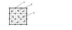
図1は本発明のドットパターンの一例であるGRID1を示す説明図である。図2はドットパターンの情報ドットおよびそれに定義されたデータのビット表示の一例を示す拡大図である。図3(a)、(b)はキードット(このキードットは本発明のディレクションドットとは異なる)を中心に配置した情報ドットを示す説明図である。 FIG. 1 is an explanatory diagram showing GRID1, which is an example of the dot pattern of the present invention. FIG. 2 is an enlarged view showing an example of a dot pattern information dot and a bit display of data defined therein. FIGS. 3A and 3B are explanatory diagrams showing information dots arranged around a key dot (this key dot is different from the direction dot of the present invention).
本発明のドットパターンを用いた情報入出力方法は、ドットパターン1の生成と、そのドットパターン1の認識と、このドットパターン1から情報およびプログラムを出力する手段とからなる。すなわち、ドットパターン1をカメラにより画像データとして取り込み、まず、基準格子点ドット4を抽出し、次に本来基準格子点ドット4がある位置にドットが打たれていないことによってキードット2(ここでのキードット2は本発明のディレクションドットとは異なる)を抽出し、次に情報ドット3を抽出することによりデジタル化して情報領域を抽出して情報の数値化を図り、その数値情報より、このドットパターン1から情報およびプログラムを出力させる。たとえば、このドットパターン1から音声等の情報やプログラムを、情報出力装置、パーソナルコンピュータ、PDAまたは携帯電話等に出力させる。 The information input / output method using a dot pattern according to the present invention includes generation of a
本発明のドットパターン1の生成は、ドットコード生成アルゴリズムにより、音声等の情報を認識させるために微細なドット、すなわち、キードット、情報ドット、基準格子点ドット4を所定の規則に則って配列する。図1に示すように、情報を表すドットパターン1のブロックは、キードット2を中心に5×5の基準格子点ドット4を配置し、4点の基準格子点ドット4に囲まれた中心の仮想格子点5の周囲に情報ドット3を配置する。このブロックには任意の数値情報が定義される。なお、図1の図示例では、ドットパターン1のブロック(太線枠内)を4個並列させた状態を示している。ただし、ドットパターン1は4ブロックに限定されないことはもちろんである。 The
1つのブロックに1つの対応した情報およびプログラムを出力させ、または、複数のブロックに1つの対応した情報およびプログラムを出力させることができる。 One corresponding information and program can be output to one block, or one corresponding information and program can be output to a plurality of blocks.
基準格子点ドット4は、カメラでこのドットパターン1を画像データとして取り込む際に、そのカメラのレンズの歪みや斜めからの撮像、紙面の伸縮、媒体表面の湾曲、印刷時の歪みを矯正することができる。具体的には歪んだ4点の基準格子点ドット4を元の正方形に変換する補正用の関数(Xn,Yn)=f(Xn’,Yn’)を求め、その同一の関数で情報ドット3を補正して、正しい情報ドット3のベクトルを求める。When the
ドットパターン1に基準格子点ドット4を配置してあると、このドットパターン1をカ
メラで取り込んだ画像データは、カメラが原因する歪みを補正するので、歪み率の高いレンズを付けた普及型のカメラでドットパターン1の画像データを取り込むときにも正確に認識することができる。また、ドットパターン1の面に対してカメラを傾けて読み取っても、そのドットパターン1を正確に認識することができる。If the
キードット2は、図1に示すように、矩形状に配置した基準格子点ドット4の略中心位置にある1個の基準格子点ドット4を一定方向にずらして配置したドットである。このキードット2は、情報ドット3を表す1ブロック分のドットパターン1の代表点である。たとえば、ドットパターン1のブロックの中心の基準格子点ドット4を上方に0.2mmずらしたものである。情報ドット3がX,Y座標値を表す場合に、キードット2を下方に0.2mmずらした位置が座標点となる。ただし、この数値はこれに限定されずに、ドットパターン1のブロックの大小に応じて可変し得るものである。 As shown in FIG. 1, the
情報ドット3は種々の情報を認識させるドットである。この情報ドット3は、キードット2を代表点にして、その周辺に配置すると共に、4点の基準格子点ドット4で囲まれた中心を仮想格子点5にして、これを始点としてベクトルにより表現した終点に配置したものである。たとえば、この情報ドット3は、基準格子点ドット4に囲まれ、図2に示すように、その仮想格子点5から0.2mm離れたドットは、ベクトルで表現される方向と長さを有するために、時計方向に45度ずつ回転させて8方向に配置し、3ビットを表現する。したがって、1ブロックのドットパターン1で3ビット×16個=48ビットを表現することができる。 The information dot 3 is a dot for recognizing various information. The information dot 3 is arranged around the
なお、図示例では8方向に配置して3ビットを表現しているが、これに限定されずに、16方向に配置して4ビットを表現することも可能であり、種々変更できることはもちろんである。 In the illustrated example, 3 bits are expressed by arranging in 8 directions. However, the present invention is not limited to this, and 4 bits can be expressed by arranging in 16 directions. Of course, various changes can be made. is there.
キードット2、情報ドット3または基準格子点ドット4のドットの径は、見栄えと、紙質に対する印刷の精度、カメラの解像度および最適なデジタル化を考慮して、0.1mm程度が望ましい。 The diameter of the
また、撮像面積に対する必要な情報量と、各種ドット2,3,4の誤認を考慮して基準格子点ドット4の間隔は縦・横1mm前後が望ましい。基準格子点ドット4および情報ドット3との誤認を考慮して、キードット2のずれは格子間隔の20%前後が望ましい。 In addition, in consideration of a necessary amount of information with respect to the imaging area and misidentification of the
この情報ドット3と、4点の基準格子点ドット4で囲まれた仮想格子点との間隔は、隣接する仮想格子点5間の距離の15〜30%程度の間隔であることが望ましい。情報ドット3と仮想格子点5間の距離がこの間隔より近い?と、ドット同士が大きな塊と視認されやすく、ドットパターン1として見苦しくなるからである。逆に、情報ドット3と仮想格子点5間の距離がこの間隔より遠い?と、隣接するいずれの仮想格子点5を中心にしてベクトル方向性を持たせた情報ドット3であるかの認定が困難になるためである。 The distance between the
たとえば,情報ドット3は、図3(a)に示すように、キードット2を中心に時計回りでI1からI16を配置する格子間隔は1mmであり、4mm×4mmで3ビット×16=48ビットを表現する。For example, the
なお、ブロック内に個々に独立した情報内容を有し、かつ他の情報内容に影響されないサブブロックをさらに設けることができる。図3(b)はこれを図示したものであり、4つの情報ドット3で構成されるサブブロック[I1、I2、I3、I4]、[I5、I6、
I7、I8]、[I9、I10、I11、I12]、[I13、I14、I15、I16]は
各々独立したデータ(3ビット×4=12ビット)が情報ドット3に展開されるようにな
っている。このようにサブブロックを設けることにより、エラーチェックをサブブロック単位で容易に行うことができる。In addition, it is possible to further provide sub-blocks having independent information contents in the block and not affected by other information contents. FIG. 3B illustrates this, and sub-blocks [I1 , I2 , I3 , I4 ], [I5 , I6 ,
I 7, I 8], [ I 9, I 10, I 11, I 12], [I 13, I 14, I 15, I 16] Each independent data (3 bits × 4 = 12 bits) information The
情報ドット3のベクトル方向(回転方向)は、30度〜90度毎に均等に定めるのが望ましい。 It is desirable that the vector direction (rotation direction) of the
図4は情報ドット3およびそこに定義されたデータのビット表示の例であり、他の形態を示すものである。 FIG. 4 shows an example of the bit display of the
また、情報ドット3について基準格子点ドット4で囲まれた仮想格子点5から長・短の2種類を使用し、ベクトル方向を8方向とすると、4ビットを表現することができる。このとき、長い方が隣接する仮想格子点5間の距離の25〜30%程度、短い方は15〜20%程度が望ましい。ただし、長・短の情報ドット3の中心間隔は、これらのドットの径より長くなることが望ましい。 In addition, using two types of
4点の基準格子点ドット4で囲まれた情報ドット3は、見栄えを考慮し、1ドットが望ましい。しかし、見栄えを無視し、情報量を多くしたい場合は、1ベクトル毎に、1ビットを割り当て情報ドット3を複数のドットで表現することにより、多量の情報を有することができる。たとえば、同心円8方向のベクトルでは、4点の格子ドット4に囲まれた情報ドット3で28の情報を表現でき、1ブロックの情報ドット16個で2128となる。The information dot 3 surrounded by the four reference
図5は情報ドットおよびそこに定義されたデータのビット表示の例であり、(a)はドットを2個、(b)はドットを4個および(c)はドットを5個配置したものを示すものである。 FIG. 5 shows an example of information dot and bit display of data defined therein. (A) shows two dots, (b) shows four dots, and (c) shows five dots arranged. It is shown.
図6はドットパターンの変形例を示すものであり、(a)は情報ドット6個配置型、(b)は情報ドット9個配置型、(c)は情報ドット12個配置型、(d)は情報ドット36個配置型の概略図である。 FIG. 6 shows a modification of the dot pattern, where (a) is a six information dot arrangement type, (b) is a nine information dot arrangement type, (c) is a 12 information dot arrangement type, and (d). Is a schematic diagram of a 36 information dot arrangement type.
図1と図3に示すドットパターン1は、1ブロックに16(4×4)の情報ドット3を配置した例を示している。しかし、この情報ドット3は1ブロックに16個配置することに限定されずに、種々変更することができる。たとえば、必要とする情報量の大小またはカメラの解像度に応じて、情報ドット3を1ブロックに6個(2×3)配置したもの(a)、情報ドット3を1ブロックに9個(3×3)配置したもの(b)、情報ドット3を1ブロックに12個(3×4)配置したもの(c)、または情報ドット3を1ブロックに36個配置したもの(d)がある。 The
(ドットパターンの説明:GRID3)
次にGRID3について説明する。(Description of dot pattern: GRID3)
Next, GRID3 will be described.
図7は本発明のドットパターンの一例を示す説明図、図8はドットパターンの情報ドットおよびそれに定義されたデータのビット表示の一例を示す拡大図、図9(a)、(b)、(c)はキードットと情報ドットとの配置状態を示す説明図である。 FIG. 7 is an explanatory diagram showing an example of the dot pattern of the present invention, FIG. 8 is an enlarged view showing an example of the bit display of the information dot of the dot pattern and the data defined in the dot pattern, and FIGS. c) is an explanatory diagram showing an arrangement state of key dots and information dots.
本発明のドットパターンを用いた情報入出力方法は、ドットパターン1の認識と、このドットパターン1から情報およびプログラムを出力する手段とからなる。 The information input / output method using the dot pattern of the present invention includes recognition of the
すなわち、ドットパターン1をカメラにより画像データとして取り込み、まず、基準格子点ドット4を抽出し、これを仮想基準格子点6の位置であると判定し、これらの仮想基準格子点6を結ぶ直線を基準格子線7とする。そして、この基準格子線7上で、本来基準
格子点ドット4があるべき仮想基準格子点6の位置にドットが配置されていない場合、この仮想基準格子点6の周辺のドットを抽出し、これをキードット2(ブロックの四隅の角部)とする。そして、次に前記仮想基準格子点6同士を結ぶ縦横の格子線8a、8bを設定し、その格子線同士の交点を仮想格子点11(第1の仮想格子点)とする。そしてこの仮想格子点11の周囲のドットを探索し、その仮想格子点11からの距離と方向とで定義される情報ドット3を抽出する。That is, the
また、仮想基準格子点6同士を斜め方向に結ぶ斜め格子線8cを想定し、この斜め格子線8c同士の交点も仮想格子点12(第2の仮想格子点)とする。そしてこの仮想格子点12の周囲のドットも探索し、その仮想格子点12からの距離と方向とで定義される情報ドット3を抽出する。 Further, an
次に、キードット2の仮想基準格子点6または仮想格子点11からの方向によって当該ブロックの向きが決定される。たとえば、キードット2が仮想格子点から+y方向にずれていた場合には縦方向を正位としてブロック内の情報ドット3を認識すればよい。 Next, the direction of the block is determined by the direction of the
また、キードット2が仮想基準格子点6または仮想格子点11から−y方向にずれていれば当該ブロックをブロック中心を軸に180度回転させた方向を正位としてブロック内の情報ドット3を認識すればよい。 If the
また、キードット2が仮想基準格子点6または仮想格子点11から−x方向にずれていれば当該ブロックをブロック中心を軸に時計方向に90度回転させた方向を正位としてブロック内の情報ドット3を認識すればよい。 Further, if the
また、キードット2が仮想基準格子点6または仮想格子点11から+x方向にずれていれば当該ブロックをブロック中心を軸に反時計方向に90度回転させた方向を正位としてブロック内の情報ドット3を認識すればよい。 If the
光学読取手段で読み取られたドットパターン1の画像がフレームバッファに蓄積されると、当該光学読取手段の中央処理装置(CPU)は、フレームバッファのドットを解析して、各情報ドット3の仮想格子点11、12からの距離と方向によって情報ドット3毎に定義された数値を復号する。そしてこれらの数値はxy座標またはコードとして光学読取手段またはパーソナルコンピュータのメモリに格納された情報と照合されて、前記xy座標またはコードに対応する音声、画像、動画、文字、プログラム等が読み出されて、表示手段、音声・画像出力手段とから出力される。 When the image of the
本発明のドットパターン1の生成は、ドットコード生成アルゴリズムにより、音声等の情報を認識させるために微細なドット、すなわち、キードット2、情報ドット3、基準格子点ドット4を所定の規則に則って配列する。 The
図7に示すように、印刷物等の媒体面の、正方形または長方形の矩形領域をブロックとする。そして、該ブロックの枠を構成する縦方向および横方向の直線を基準格子線7(図1で太枠で示した線)として、該基準格子線7上の所定間隔毎に仮想基準格子点6を設け、仮想基準格子点6上に基準格子点ドット4を配置する。次に、該仮想基準格子点6同士を結びかつ前記基準格子線7と平行な直線を格子線8a、8bとし、格子線8a、8b同士の交点を仮想格子点11(第1の仮想格子点)とする。 As shown in FIG. 7, a rectangular area of a square or a rectangle on the surface of a medium such as a printed material is a block. Then, the vertical and horizontal straight lines constituting the frame of the block are set as reference grid lines 7 (lines indicated by thick frames in FIG. 1), and virtual reference grid points 6 are provided at predetermined intervals on the reference grid lines 7. And the reference
そしてさらに、前記仮想基準格子点6同士を斜め方向に結ぶ斜め格子線8cを設定し、この斜め格子線8c同士の交点も仮想格子点12(第2の仮想格子点)とする。 Further, an
このように設定された仮想格子点11、12を基準に距離と方向を有する1または複数の情報ドット3をそれぞれ配置してドットパターンを生成する。 A dot pattern is generated by arranging one or a plurality of
カメラでこのドットパターン1を画像データとして取り込む際に、そのカメラのレンズの歪みや斜めからの撮像、紙面の伸縮、媒体表面の湾曲、印刷時の歪みを前記基準格子点ドット4によって矯正することができる。具体的には歪んだ4点の仮想格子点を元の正方形に変換する補正用の関数(Xn,Yn)=f(Xn’,Yn’)を求め、その同一の関数で情報ドットを補正して、正しい情報ドット3のベクトルを求める。When the
ドットパターン1に基準格子点ドット4を配置してあると、このドットパターン1をカメラで取り込んだ画像データは、カメラが原因する歪みを補正するので、歪み率の高いレンズを付けた普及型のカメラでドットパターン1の画像データを取り込むときにも正確に認識することができる。また、ドットパターン1の面に対してカメラを傾けて読み取っても、そのドットパターン1を正確に認識することができる。 If the
キードット2は、図7に示すように、矩形状に配置した仮想格子点の略中心位置にある1個の仮想格子点11を基準に距離と方向によって配置されたドットである。このキードット2は、ひとまとまりの情報ドット群を表す1ブロック分のドットパターン1の代表点である。たとえば、ドットパターン1のブロックの中心の仮想格子点11から上方に0.2mmずれた位置に配置されているものである。したがって、情報ドット3が仮想格子点からのX、Y座標値で定義される場合には、キードット2から下方に0.2mmの距離の位置が仮想格子点(座標点)となる。ただし、この数値(0.2mm)はこれに限定されずに、ドットパターン1のブロックの大小に応じて可変し得るものである。 As shown in FIG. 7, the
情報ドット3は種々の情報を認識させるドットである。この情報ドット3は、図12の場合、キードット2を代表点にして、その周辺に配置すると共に、4点の仮想格子点11(第1の仮想格子点)で囲まれた中心を仮想格子点12(第2の仮想格子点)にして、これを始点としてベクトルにより表現した終点に配置したものである。たとえば、この情報ドット3は、仮想格子点11、12に囲まれ、図8に示すように、その仮想格子点11,12から0.2mm離れたドットは、ベクトルで表現される方向と長さを有するために、時計方向に45度ずつ回転させて8方向に配置し、3ビットを表現している。 The information dot 3 is a dot for recognizing various information. In the case of FIG. 12, the information dot 3 is arranged around the
この図によれば、1ブロックのドットパターン1で3ビット×16個=48ビットを表現することができる。 According to this figure, 3 bits × 16 = 48 bits can be expressed by one block of
なお、図示例では8方向に配置して3ビットを表現しているが、これに限定されずに、16方向に配置して4ビットを表現することも可能であり、種々変更できることはもちろんである。 In the illustrated example, 3 bits are expressed by arranging in 8 directions. However, the present invention is not limited to this, and 4 bits can be expressed by arranging in 16 directions. Of course, various changes can be made. is there.
さらに、図7では全ての仮想格子点において、この仮想格子点を始点としてその終点位置に情報ドットを配置したが、これに限定されることなく、仮想格子点上にドットが配置されているか否かで情報を定義するようにしてもよい。たとえば仮想格子点上にドットが配置されていれば「1」、配置されていなければ「0」というように情報を定義することができる。 Further, in FIG. 7, information dots are arranged at the end positions of the virtual grid points starting from the virtual grid points. However, the present invention is not limited to this, and whether or not dots are arranged on the virtual grid points. You may make it define information. For example, information can be defined as “1” if dots are arranged on virtual grid points, and “0” if dots are not arranged.
キードット2、情報ドット3または基準格子点ドット4のドットの径は、見栄えと、紙質に対する印刷の精度、カメラの解像度および最適なデジタル化を考慮して、0.1mm程度が望ましい。 The diameter of the
また、撮像面積に対する必要な情報量と、各種ドット2,3,4の誤認を考慮して基準
格子点ドット4の間隔は縦・横1mm前後が望ましい。基準格子点ドット4および情報ドット3との誤認を考慮して、キードット2のずれは格子間隔の20%前後が望ましい。In addition, in consideration of a necessary amount of information with respect to the imaging area and misidentification of the
この情報ドット3と、仮想格子点11または12との間隔は、隣接する仮想格子点11,12間の距離の15〜30%程度の間隔であることが望ましい。情報ドット3と仮想格子点11,12間の距離がこの間隔より近いと、ドット同士が大きな塊と視認されやすく、ドットパターン1として見苦しくなるからである。逆に、情報ドット3と仮想格子点間の距離がこの間隔より遠いと、隣接するいずれかの仮想格子点11,12を中心にしてベクトル方向性を持たせた情報ドット3であるかの認定が困難になるためである。 The distance between the
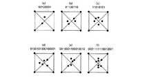
図9は、ブロック内における情報ドット3の読取順を示したものであり、同図中の丸付き数字は、それぞれ仮想格子点11,12毎に配置された情報ドット3の配置領域を意味しているものとする。 FIG. 9 shows the reading order of the
たとえば、図9(a)の場合、ブロック中心の(1)(図中で丸で囲まれた数字の「1」を意味している、以下同じ)を中心として、そこから時計回りで(1)から(25)が配置されている。このときの格子間隔はたとえば1mmであり、4mm×4mmで3ビット×1625=4875ビットを表現する。 For example, in the case of FIG. 9A, the block center (1) (meaning the number “1” circled in the figure, the same shall apply hereinafter) is used as the center and clockwise (1 ) To (25) are arranged. The lattice spacing at this time is 1 mm, for example, and 4 bits × 4 mm represents 3 bits × 1625 = 4875 bits.
図9(b)は、ブロックの左上の矩形領域の情報ドット(1)から縦方向に順番に(4)まで配置した後、縦横方向の格子線同士の交点に配置された情報ドット(5)〜(7)を配置している。 FIG. 9B shows information dots (5) arranged at the intersections of vertical and horizontal grid lines after being arranged in the vertical direction from the information dots (1) in the upper left rectangular area to (4) in order. (7) are arranged.
図9(c)は、ブロックの左上の矩形領域の情報ドット(1)から縦方向に(16)まで順番に配置した後、縦横の格子線同士の交点に配置された情報ドット(17)〜(25)を配置している。 FIG. 9C shows information dots (17) to (17) arranged at intersections of vertical and horizontal grid lines after being arranged in order from the information dot (1) in the rectangular area at the upper left of the block in the vertical direction to (16). (25) is arranged.
図10は情報ドットおよびそこに定義されたデータのビット表示の例であり、他の形態を示すものである。 FIG. 10 shows an example of the information dot and the bit display of the data defined therein, and shows another form.
また、情報ドット3について基準格子点ドット4で囲まれた仮想格子点11,12から短(図10の上段)・長(図10の下段)の2種類を使用し、ベクトル方向を8方向とす
ると、4ビットを表現することができる。このとき、長い方が隣接する仮想格子点間の距離の25〜30%程度、短い方は15〜20%程度が望ましい。ただし、長・短の情報ドット3の中心間隔は、これらのドットの径より長くなることが望ましい。Further, two types of
4点の仮想格子点11,12で囲まれた情報ドット3は、見栄えを考慮し、1ドットが望ましい。しかし、見栄えを無視し、情報量を多くしたい場合は、1ベクトル毎に、1ビットを割り当て情報ドット3を複数のドットで表現することにより、多量の情報を有することができる。たとえば、同心円8方向のベクトルでは、4点の基準格子点ドット4に囲まれた情報ドット3で28の情報を表現でき、1ブロックの情報ドット16個で2128となる。The information dot 3 surrounded by the four
図11は情報ドット3およびそこに定義されたデータのビット表示の例であり、(a)はドットを2個、(b)はドットを4個および(c)〜(e)はドットを5個、(f)は7個配置したものを示すものである。 FIG. 11 is an example of information dot 3 and bit display of data defined therein, (a) 2 dots, (b) 4 dots, and (c) to (e) 5 dots. The number (f) indicates that seven are arranged.
図12はドットパターンの変形例を示すものであり、(a)はブロック内に情報ドット3を8個配置したもの、(b)は情報ドット3を13個配置したもの、(c)は情報ドット3を18個配置したもの、(d)は情報ドット3を41個配置したものである。 FIG. 12 shows a modification of the dot pattern, where (a) shows eight
前述の図7と図9に示すドットパターン1は、1ブロックに25個の情報ドット3を配置した例を示している。しかし、この情報ドット3は1ブロックに25個配置することに限定されずに、種々変更することができる。たとえば、必要とする情報量の大小またはカメラの解像度に応じて、情報ドット3を1ブロックに8個配置したもの(図12(a))、情報ドット3を1ブロックに13個配置したもの(図12(b))、情報ドット3を1ブロックに18個配置したもの(図12(c))、または情報ドット3を1ブロックに41個配置したもの(図12(d))がある。 The
(ドットパターンの説明:GRID4)
次にGRID4について説明する。(Description of dot pattern: GRID4)
Next, GRID4 will be described.
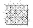
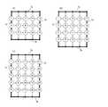
図13は、本発明の実施形態であるドットパターンを具体的に示したものであり、(a)は4×4格子、(b)は5×4格子、(c)は6×4格子分のドットパターンを示している。 FIG. 13 specifically shows a dot pattern according to an embodiment of the present invention, where (a) is a 4 × 4 lattice, (b) is a 5 × 4 lattice, and (c) is a 6 × 4 lattice. The dot pattern is shown.
同図(a)において、まず四角形を構成する縦横方向の基準格子線7a〜7dを設け、その四角形内の所定間隔毎に仮想格子点13が配置されている。 In FIG. 2A, first, vertical and horizontal
なお、基準格子線7a〜7dおよび仮想格子点13については、実際に紙面(媒体面)に印刷されるわけではなく、あくまでもコンピュータの画像メモリ上にドットパターンの配置の際、またはドットパターンの読取の際に仮想的に設定されるものである。 Note that the
次に、上下の横方向の基準格子線7a、7b上の仮想基準格子点14上に基準格子点ドット4を配置する。 Next, the reference
次に、仮想格子点13同士を結ぶ縦横方向の格子線8a、8bを想定し、この格子線8a、8b同士の交点を同じく仮想格子点13とする。 Next, assuming vertical and
次に、仮想格子点13を基準に距離と方向とを有する情報ドット3を仮想格子点13毎に1または2以上配置してドットパターンを生成する。なお、図13では仮想格子点13毎に1つの情報ドット3が配置されている。 Next, one or
以上に説明した図13(a)は格子数を縦方向に4個、横方向に4個の単位で情報ドット3を配置した場合(4×4格子)であるが、同図(b)は5×4格子、(c)は6×4格子をそれぞれ示している。 FIG. 13A described above is a case where the
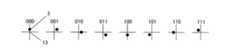
図14は情報ドット3の定義を示したものであり、仮想格子点13を中心に情報ドット3の方向で値を定義したものである。同図では仮想格子点を通過する格子線を基準に時計方向に45度ずつ8方向に情報ドットを配置することによって、合計8通り(二進法で000から111、3ビット)の情報を定義できるようになっている。 FIG. 14 shows the definition of the
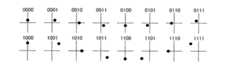
また、図15は前記方向にさらに距離を2段階にすることによって合計16通り(二進法で)、すなわち0000〜1111(4ビット)の情報を定義できるようになっている。 Further, in FIG. 15, by further dividing the distance in two directions, a total of 16 kinds of information (in binary), that is, 0000-1111 (4 bits) can be defined.
図16は、仮想格子点13を中心に同心円上に複数の情報ドット3を配置する場合であり、その位置がドットがある場合を1、ない場合を0として定義することにより、8ビットを定義でき、すなわち鉛直方向に位置するドットを1ビット目として時計回りにビット情報を定義できる。 FIG. 16 shows a case where a plurality of
図17は当該同心円を2つにしたものであり、16ビットを定義できる。このようにすることにより、1つの仮想格子点13に対して膨大な情報量を定義することが可能となる。 FIG. 17 shows two concentric circles, and 16 bits can be defined. In this way, it is possible to define an enormous amount of information for one
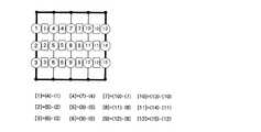
図18は、光学読取手段における情報ドット3の読取順を説明するためのものである。同図における丸付き数字は便宜的なものであり、実際には図13(a)〜(c)に示されたドットパターンとなっている。 FIG. 18 is for explaining the reading order of the
同図(a)では、まず左側縦方向の基準格子線7cに沿って縦方向に仮想格子点毎の情報ドットを読み取った後(丸付き数字(1)〜(3))、次の縦方向格子線8b上の仮想格子点13を上から順番に読み取る(丸付き数字(4)〜(6))。このようにして順次仮想格子点13毎の読取を実行する。 In FIG. 9A, after reading information dots for each virtual grid point in the vertical direction along the left-side vertical
なお、以上の説明では格子毎の読取順は縦方向の格子線8bの左から順番としたが、情報を配置・読み取る格子順は任意に設定してよいことはもちろんである。 In the above description, the reading order for each grid is the order from the left of the
図19は、基準格子線上の仮想格子点13上に、基準格子点ドット4の代わりにキードット2を配置した例である。基準格子線7aの中間位置の仮想格子点13を基準に上方向にずらした位置にキードット2を配置している。 FIG. 19 shows an example in which the
これらのキードット2により、ドットパターンの方向を定義することができる。 With these
図20は差分法を用いた情報ドット3の読取方法について説明したものである。以下では図面の四角形数字を[]、丸付き数字を()で表現する。 FIG. 20 illustrates a method for reading
すなわち、図20では、4×4格子において、(4)の情報ドットの値と(1)の情報ドットの値の差分により値[1]を表現している。 That is, in FIG. 20, in the 4 × 4 lattice, the value [1] is expressed by the difference between the information dot value (4) and the information dot value (1).
同様に、[2]は(5)と(2)の差分、[3]は(6)と(3)の差分で表現できる。[4]〜[12]も同様に表現している。 Similarly, [2] can be expressed as a difference between (5) and (2), and [3] can be expressed as a difference between (6) and (3). [4] to [12] are expressed in the same manner.
[1]〜[12]は以下の情報ドット間の差分で表現することができる。 [1] to [12] can be expressed by the following differences between information dots.
[1]=(4)−(1)
[2]=(5)−(2)
[3]=(6)−(3)
[4]=(7)−(4)
[5]=(8)−(5)
[6]=(9)−(6)
[7]=(10)−(7)
[8]=(11)−(8)
[9]=(12)−(9)
[10]=(13)−(10)
[11]=(14)−(11)
[12]=(15)−(12)
このような差分法を用いることにより、1つの真値に対して異なる複数のドットパターンを生成することができ、セキュリティを高めることができる。[1] = (4)-(1)
[2] = (5)-(2)
[3] = (6)-(3)
[4] = (7)-(4)
[5] = (8)-(5)
[6] = (9)-(6)
[7] = (10) − (7)
[8] = (11)-(8)
[9] = (12) − (9)
[10] = (13)-(10)
[11] = (14)-(11)
[12] = (15)-(12)
By using such a difference method, a plurality of different dot patterns can be generated for one true value, and security can be improved.
(GRID1におけるディレクションドットの説明)
以上の図1〜図20の説明は主として本発明者が提唱しているドットパターンの一例を説明したものである。以下の説明では、キードット2を用いることなくディレクションドットによってブロックの方向を定義する場合について詳細に説明する。(Description of direction dots in GRID1)
The above description of FIGS. 1 to 20 mainly describes an example of a dot pattern proposed by the present inventor. In the following description, the case where the direction of the block is defined by the direction dot without using the
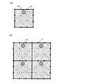
図21(a)および(b)は、図1〜図20で説明したGRID1によるドットパターンを前提にしてディレクションドット21を配置した例である。 FIGS. 21A and 21B are examples in which the
この例では、基準格子点ドット4に囲まれた領域の中心点からのずらし方によって情報を定義している。したがって、全ての格子領域に情報ドット3を配置することができるが、3×3個の中央の格子領域のみはディレクションドット21が配置されている。 In this example, information is defined by how to shift from the center point of the area surrounded by the reference
ディレクションドット21の配置領域では、ディレクションドットは中心点から縦横方向にずれた位置に配置されて方向と情報とを表している。すなわち、図21(a)では、ディレクションドット21が中心から上方にずらした位置(+Y方向)に配置されているので、当該ブロックは上向きであることがわかる。これが中心から下方にずらした位置(−Y方向)に配置されている場合は、当該ブロックは下向きであることがわかる。同様に、中心から左方向にずらした位置(−X方向)に配置されている場合は、当該ブロックは左向き、中心から右方向にずらした位置(+X方向)に配置されている場合は、当該ブロックは右向きであることがわかる。 In the area where the
また、ディレクションドット21以外の格子領域では、中心点から斜め方向にずらすことにより、情報を定義している。この定義の仕方については前述したので説明は省略する。 Further, in the lattice area other than the direction dot 21, information is defined by shifting in an oblique direction from the center point. Since this method of definition has been described above, a description thereof will be omitted.
なお、このような方向基準が他の格子領域とは異なる領域(ディレクションドット21が配置される格子領域)は、その中央に配置した場合にはディレクションドット21の方向でブロックを定義をすることになるが、この方向基準の異なる格子領域をブロックの他の領域に配置した場合(ディレクション領域)には、その配置位置によってブロックの方向を定義することができる(図40参照)。また、このような方向基準の異なる格子領域を複数設けてその配置態様によってブロックの方向を定義することもできる(図34〜図37)。これらの場合には方向基準の異なる格子領域を配置するだけでブロックの方向が定義できるため、当該格子領域に配置される情報ドット3は必ずしもブロックの方向と一致させる必要はない。この点については後で詳しく説明する。 It should be noted that such a region whose direction reference is different from other lattice regions (lattice region where the direction dot 21 is arranged) defines a block in the direction of the direction dot 21 when arranged in the center. However, when the lattice regions having different direction standards are arranged in another region of the block (direction region), the direction of the block can be defined by the arrangement position (see FIG. 40). It is also possible to provide a plurality of such lattice regions with different direction standards and define the direction of the block according to the arrangement mode (FIGS. 34 to 37). In these cases, since the direction of the block can be defined simply by arranging the grid areas having different direction references, the
このように、ディレクション領域では縦横方向、それ以外の領域では斜め方向に情報ドット3を配置することによって、キードット2のために基準格子点ドット4のいずれかをずらして基準格子点の等間隔性を犠牲にすることがないため、ドットパターンの読取アルゴリズムを簡易化できる。また、ディレクション領域にはそのまま情報ドット3を配置することができるため、情報ドット3を犠牲にすることなくブロックの方向を定義できる。さらに、ディレクションドット21を配置した場合であっても中心点からのずれ量(中心点からの長さ)で情報を定義することができ、情報ドット3とディレクションドット21とを兼用することが可能である。 In this way, by arranging the
図47は、ディレクションドットと情報ドットの判定アルゴリズムを説明するための図である。 FIG. 47 is a diagram for explaining a determination algorithm for direction dots and information dots.
ディレクションドット21と情報ドット3との判別に際して、以下のような手順を実行する。 When discriminating between the direction dot 21 and the
(1)s=|l0−l2|を算出する。(1) s = | l0 −l2 | is calculated.
(2)t=|l3−l1|を算出する。(2) t = | l3 −l1 | is calculated.
(3)s−tを算出する。 (3) Calculate st.
(4)s−tが所定値p以上であれば情報ドット、所定値p未満であればディレクションドットと判定する。 (4) If s−t is not less than the predetermined value p, it is determined as an information dot, and if it is less than the predetermined value p, it is determined as a direction dot.
具体的には、図47(a)の場合、
s−t=|l0−l2|−|l3−l1|=|l0−l2|
|l0−l2|≧pであれば情報ドットである。Specifically, in the case of FIG.
s−t = | l0 −l2 | − | l3 −l1 | = | l0 −l2 |
If | l0 −l2 | ≧ p, it is an information dot.
同図(b)の場合、
s−t=|l0−l2|−|l3−l1|=0
0<pであればディレクションドットである。In the case of FIG.
s−t = | l0 −l2 | − | l3 −l1 | = 0
If 0 <p, it is a direction dot.
なお、pの値は任意に設定できるが120pixel2程度が好ましいがこれに限定されるものではない。Although the value of p can be set arbitrarily, it is preferably about 120 pixel2, but is not limited thereto.
図21(a)は、3×3=9個の格子領域で形成されたブロックを示しており、同図(b)はこのブロックを縦横2個ずつ配置した例を示している。 FIG. 21A shows a block formed of 3 × 3 = 9 lattice regions, and FIG. 21B shows an example in which two blocks are arranged vertically and horizontally.
図22(a)および(b)は、図21(a)および(b)に対応した情報ドット3の格子領域毎の配置順を示したものである。情報ドット3の配置順はこれに限定されるものではない。 FIGS. 22A and 22B show the arrangement order of the
(GRID3:ディレクションドットの配置例)
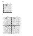
図23(a)および(b)は、ディレクションドット21を別のドットパターン(GRID3)に適用した場合の図である。(GRID3: Direction dot arrangement example)
FIGS. 23A and 23B are diagrams when the direction dot 21 is applied to another dot pattern (GRID3).
GRID1では、4点の基準格子点ドットに囲まれた領域内に情報ドット3を配置したが、GRID3では、基準格子点の位置にも情報ドット3を配置している。この例では、ブロック内で、いずれかの基準格子点に着目して、ディレクションドット21を配置することができる。 In GRID1,
図23(a)では、4×4=16個の格子領域のうち、左上の格子領域の右下に位置する基準格子点をディレクションドット21の配置場所としている。ディレクションドット21の配置場所をこのようにした場合、当該ブロックの中心24を中心に、90度ずつ開店回転させた位置(23a,23b,23c)ではディレクションドット21と同じ方向(縦横方向)に情報ドット3が配置されているとどれがディレクションドット21であるか判別できずに、ブロックの方向を定義できない可能性がある。 In FIG. 23A, the reference grid point located at the lower right of the upper left grid area among the 4 × 4 = 16 grid areas is set as the location of the
そこで、ディレクションドット21の配置場所以外の基準格子点では、情報ドットの配置は斜め方向に配置させている。これにより、ディレクションドット21の探索が容易となる。 Therefore, at the reference grid points other than the location of the
図23(a)では、ディレクションドット21のドットの位置、すなわち同図では基準格子点から上方にドットが配置されていることで当該ブロックが上向きであることを定義している。 In FIG. 23A, the position of the direction dot 21, that is, the dot is arranged above the reference lattice point in FIG.
しかし、このようにドットの位置そのものでブロックの向きを定義することに限られず、ドットを縦横方向に配置する領域を同図に示すように、ブロック中の左上に配置すること自体でブロックの方向を定義することもできる。この場合、当該領域に配置するドットは必ずしもブロックの向きと一致させる必要はなく、基準格子点から右、左、下の方向に配置してもよい。このように基準格子点からの方向が、他の情報ドット3とは異なる方向基準で情報を定義する領域(ディレクション領域21a:このディレクション領域21aでは基準格子点の縦横方向に情報ドット3が配置され、それ以外の領域の格子線の交点を基準格子点とした領域では斜め方向にドットが配置されている)をブロック内のあらかじめ定められた位置に配置することによって、ブロックの方向を定義できる。つまりディレクション領域21aが左上に配置されていれば当該ブロックは上向きである。また、当該領域(ディレクション領域21a)の配置場所だけでブロックの方向を定義できるため、当該領域(ディレクション領域21a)の情報ドット3は他の情報ドット3と異なる方向でさえあれば、基準格子点からいかなる方向に配置してもよい。 However, it is not limited to defining the direction of the block by the dot position itself, as shown in the figure, the direction of the block by arranging the dot in the upper left of the block as shown in the figure. Can also be defined. In this case, the dots arranged in the area do not necessarily coincide with the block direction, and may be arranged in the right, left, and lower directions from the reference grid point. Thus, the direction in which the direction from the reference grid point is different from the
また図23(a)では、ディレクションドット21の向き(縦横方向)で他の基準格子点に配置される情報ドット3の配置方向(斜め方向)とは区別できるようにしたが、これに限らず、図23(b)に示すように、基準格子点からの長さによってディレクションドット21を識別できるようにしてもよい。同図では、ディレクションドット21のみ基準格子点からの距離を長く設定しており、他の位置(23a,23b,23c)の情報ドット3は基準格子点からの距離を短く設定している。 In FIG. 23A, the direction of the direction dots 21 (vertical and horizontal directions) can be distinguished from the arrangement direction (diagonal direction) of the
図24は、上記で説明したGRID3によるドットパターンを縦横2個で構成した場合の図、図25(a)および(b)はこれに対応する情報ドット3の配置順を示す図である。 FIG. 24 is a diagram in the case where the dot pattern based on GRID3 described above is composed of two vertically and horizontally, and FIGS. 25A and 25B are diagrams showing the arrangement order of
図24に示す場合も、基準格子点から上下左右方向にドットを配置する領域(ディレクション領域21a)がブロックの左上に配置されていることによって、当該ブロックの向きを識別できるようになっている。 Also in the case shown in FIG. 24, an area (
図26(a)および(b)は、GRID3によるドットパターンにおいて、ディレクションドット21をブロック中心に配置した場合の例を示している。 FIGS. 26A and 26B show an example in which the direction dot 21 is arranged at the block center in the dot pattern based on GRID3.
このようにディレクションドット21をブロック中心に配置することにより、他の格子点は縦横斜め方向に自由に情報ドット3を配置することができる。 By arranging the
図27は(a)および(b)は、図26(a)および(b)に対応した図であり、情報ドット3の配置順を示している。 27A and 27B are diagrams corresponding to FIGS. 26A and 26B, and show the arrangement order of the
(GRID4:ディレクションドットの配置例)
図28〜図33は、ディレクションドットをさらに別のドットパターン(GRID4)に適用した場合の図である。(GRID4: Direction dot arrangement example)
FIG. 28 to FIG. 33 are diagrams when the direction dots are applied to still another dot pattern (GRID4).
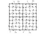
図28(a)において、このドットパターン(GRID4)では、ブロックの上下の横方向の格子線28a,28b上に基準格子点ドット4が等間隔に配置されており、それ以外の格子点を中心にそれぞれ情報ドット3が配置されている。 In FIG. 28A, in this dot pattern (GRID4), the reference
このようなドットパターンにおいて、上下の格子線28a,28bの中間に位置する中央格子線28cの1つ上の格子線上の所定の基準格子点の領域では、この基準格子点を始点として縦横方向に情報ドット3が配置されており、この領域はディレクション領域21aとなっている。 In such a dot pattern, in the region of a predetermined reference lattice point on the lattice line one above the
このディレクション領域21aでは、同一の格子線に所属する基準格子点とは情報ドット3の配置の方向基準が異なっている。すなわち、他の基準格子点の領域では基準格子点から斜め方向に情報ドット3が配置されているのに対して、ディレクション領域21aでは基準格子点から縦横方向に情報ドット3が配置されている。 In this
このように、中央格子線28cを基準にディレクション領域21aが上に配置されている場合には、当該ブロックは上向きであると識別することができる。 Thus, when the
なお、ディレクション領域21aでは、縦横方向に任意に情報ドット3を配置することもできるが、このディレクション領域21a内のドットの配置をブロックの向きと一致させたディレクションドット21としてもよいことは勿論である。 In the
また、中央格子線28c上にディレクション領域21aを設けた場合には、その中に配置されるドットはディレクションドット21としてブロックの方向を示すことになる。 When the
このようなドットパターン(GRID4)において、いずれかの格子点の位置をディレクションドット21とした場合、上下の格子線28a,28bの中間に位置する中央格子線28cを軸にして線対称位置にある格子点の情報ドット3は、ディレクションドット21とは異なるドットの配置となるようにしている。すなわち、ディレクションドット21は格子点から上下左右にずれた位置に配置するようにし、それと線対称位置にある格子点では情報ドット3は格子点から斜め方向にずらして配置するようにしている。In such a dot pattern (GRID4), when either of the position direction dot 21 of grid points, upper and
このようなドットパターン(GRID4)では、基準格子点4が等間隔に配置されているのは上下の格子線28a,28bのみであるから、これで当該ブロックの縦方向が識別できる。次に、中央の格子線28cを基準に互いの対称位置にそれぞれ斜め方向、縦方向にドットが配置されている部位を探索する。ここで探索された縦方向のドットがディレクションドット21である。 In such a dot pattern (GRID4), the reference grid points 4 are arranged at equal intervals only in the upper and
図28(b)は、このようなブロックを縦横2個並べた状態を示す図である。 FIG. 28B is a diagram showing a state in which two such blocks are arranged vertically and horizontally.
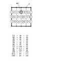
また、図29(a)は、当該ドットパターン(GRID4)の情報の配置の仕方の一例を示す説明図である。この例では、ドット毎の差分で情報を定義するようになっている。本明細書において、[1]は図面において四角形で囲まれた数字の1、(1)は図面において丸付き数字の1を意味しているものとする。ここで、たとえば、最初の情報[1]は(4)の位置にある情報ドット3の値から(1)の位置にある情報ドット3の値を減算した値で定義されている。同図に示すように、ディレクションドット21が配置された格子点のみは情報ドット3として使用していないが、このディレクションドット21にも格子点からの長さの違いで情報を意味づけてもよい。 FIG. 29A is an explanatory diagram showing an example of how the information of the dot pattern (GRID4) is arranged. In this example, information is defined by a difference for each dot. In the present specification, it is assumed that [1] means a numeral 1 surrounded by a square in the drawing, and (1) means a circled numeral 1 in the drawing. Here, for example, the first information [1] is defined by a value obtained by subtracting the value of the information dot 3 at the position (1) from the value of the information dot 3 at the position (4). As shown in the figure, only the grid point where the direction dot 21 is arranged is not used as the
また、ディレクションドット21の代わりに図28(a)で説明したように、この領域をディレクション領域21aとして情報ドット3を配置してもよいことは勿論である。 Further, as described with reference to FIG. 28A instead of the direction dot 21, it is needless to say that the information dot 3 may be arranged with this area as the
図30上図は図29に示したドットパターンのブロックを縦横2個ずつ連結したものであり、下図はその値の算出を示したものである。 The upper diagram of FIG. 30 is obtained by connecting the two dot pattern blocks shown in FIG. 29 vertically and horizontally, and the lower diagram shows the calculation of the values.
図31(a)および(b)は、GRID4によるドットパターンにおいて、ディレクションドット21をブロック中心に配置した場合の例を示している。 FIGS. 31A and 31B show an example in which the direction dot 21 is arranged at the block center in the dot pattern based on GRID4.
このようにディレクションドット21をブロック中心に配置することにより、他の格子
点は縦横斜め方向に自由に情報ドット3を配置することができる。By arranging the
図32〜図33は、図31に対応した情報の配置を示す図である。 32 to 33 are diagrams showing the arrangement of information corresponding to FIG.
(GRID1:変形パターン)
図34(a)および(b)は、GRID1のドットパターンにおいて、3×3=9個の格子領域で構成されるブロックのドットパターンにおいて、特定の格子領域(ディレクション領域)だけ情報ドット3の配置方向を他の格子領域(ディレクション領域)と変えることによって、ブロックの方向を定義している。(GRID1: deformation pattern)
FIGS. 34A and 34B show the arrangement of
すなわち、図34(a)において、左下の格子領域34a、中央の格子領域34b、左下の格子領域34cは中心から縦横方向に情報ドット3が配置され、その他の格子領域では中心から斜め方向に情報ドット3が配置されている。このように格子領域34a,34b,34cを配置することでこの格子領域を結ぶ三角形の形状、すなわち、底辺34a,34cに対する頂点34bの関係から、当該ブロックが上向きであることが認識できる。 That is, in FIG. 34A,
このように、ブロック中の情報ドット3の配置方向を変更した(中心から縦横方向に情報ドット3を配置した)格子領域34a,34b,34cの配置関係(ここでは三角形)によってブロックの方向を定義することができる。これによって、ブロック中の全ての格子領域に情報ドット3を配置することができるため、キードットのために格子領域を犠牲にすることがなく、全ての格子領域に情報ドット3を配置することができる。 In this way, the direction of the block is defined by the arrangement relationship (in this case, a triangle) of the
なお、図34(b)は、図34(a)に示したブロックを縦横方向に2個ずつ連結したものである。 Note that FIG. 34B is obtained by connecting two blocks shown in FIG. 34A in the vertical and horizontal directions.
図35(a)および(b)は、図34(a)および(b)に対応した情報ドット3の配置状態を示す図である。 FIGS. 35A and 35B are diagrams showing the arrangement state of the
図36(a)は、図34(a)の変形であり、4×4=16個の格子領域で構成されるブロックのドットパターンにおいて、特定の格子領域36a,36b,36c,36dだけ情報ドット3の配置方向を格子領域の中心から縦横方向に情報ドット3を配置し、他の格子領域(中心から斜め方向に情報ドット3を配置)と変えることによって、ブロックの方向を定義している。このブロックでは格子領域36a,36c,36dが底辺と並行に直線的に配置され、格子領域36bのみが突出している。したがって、当該ブロックはこの格子領域36bの突出方向、すなわち上向きであることがわかる。 FIG. 36 (a) is a modification of FIG. 34 (a). In a dot pattern of a block composed of 4 × 4 = 16 lattice areas, only information dots of
なお、図36(b)は、図36(a)に示したブロックを縦横方向に2個ずつ連結したものである。 Note that FIG. 36B is obtained by connecting two blocks shown in FIG. 36A in the vertical and horizontal directions.
図37(a)および(b)は、図36(a)および(b)に対応した情報ドット3の配置状態を示す図である。 FIGS. 37A and 37B are diagrams showing the arrangement state of the
このように、図34〜図37に示すように、特定の格子領域だけ情報ドット3の配置方向を他の格子領域と変えることによって、ブロックの方向を定義することでキードットによって格子領域を犠牲にすることなく、全ての格子領域に情報ドット3を配置することが可能となる。 In this way, as shown in FIGS. 34 to 37, by changing the arrangement direction of the
なお、図38および図39は、上記図34〜図37で説明した格子領域の配置を行ったとしてもブロックの方向を定義できない例を示している。 FIG. 38 and FIG. 39 show an example in which the block direction cannot be defined even if the lattice regions are arranged as described above with reference to FIGS.
すなわち、図38(a)の場合、情報ドット3を格子点の縦横方向にずらして配置する格子領域381,382,383がブロックの斜め方向に直線的に連続しており、このような特定の格子領域を結ぶ線が直線的に他のブロックにも繋がっていく場合には、ブロックの方向を定義することができない。また図38(b)も情報ドット3を格子点の縦横方向にずらして配置する格子領域384,385,386がブロックの上下方向に直線的に連続しており、ブロックの方向を定義することができない。 That is, in the case of FIG. 38A,
さらに、図38(c)の場合、情報ドット3を格子点の縦横方向にずらして配置する格子領域387,388,389が三角形を構成してはいるものの、これを180度回転した図形が395,394,389、または391,392,393のようにブロックをまたがって表れてしまうため、ブロック自体(ブロックB5を誤認識してしまう可能性がある)を定義することができなくなり、かつその方向も上下いずれであるか判別できなくなる。 Further, in the case of FIG. 38 (c), although the
図39も同様であり、情報ドット3を格子点の縦横方向にずらして配置する格子領域401,402,403を結ぶ線が三角形を構成してはいるものの、これを180度回転した図形が404,405,406のようにブロックB3,B4をまたがって表れてしまうため、本来ブロックではないブロックB5を誤認識してしまう可能性があり、正確にブロックを定義することができなくなり、かつその方向も上下いずれであるか判別できなくなる。 The same applies to FIG. 39. A line connecting
図40(a)は、図23で説明したドットパターン(GRID3)の変形例であり、ブロックの外周を構成する格子線上に等間隔の基準格子点ドット4を配置し、この基準格子点ドット4同士を縦横方向に結んだ格子線を配置し、格子線同士の交点を仮想格子点として4個の仮想格子点に囲まれた領域を格子領域としたものである。この格子領域の中心を基準に長さと方向(ベクトル)を有する情報ドット3を配置している。そして、仮想格子点も基準として情報ドット3を配置している。ここで、格子領域については、中央上の格子領域411のみ中心点から縦横方向にのみずらした情報ドット3を配置し、これ以外の格子領域は中心点から斜め方向にずらして情報ドット3を配置している。この場合、当該格子領域411の配置位置から、当該ブロックは上向きであることがわかる。 FIG. 40 (a) is a modification of the dot pattern (GRID3) described in FIG. 23, in which reference
このように特定の方向に情報ドット3を配置する格子領域411をブロックのどの位置に配置するかによって当該ブロックの方向を認識することができる。 In this way, the direction of the block can be recognized depending on the position of the
このように、格子領域411をディレクション領域として、ブロック内のその配置場所だけでブロックの方向を識別することも可能である。 As described above, it is also possible to identify the direction of the block only by the arrangement location in the block using the
すなわち、図40(a)の場合、格子領域411のみドット配置の方向基準が縦横方向となっており、当該格子領域411がディレクション領域とみることができる。 That is, in the case of FIG. 40 (a), only the
この場合、当該ディレクション領域が中央上に配置されていることによって当該ブロックは上向きであると識別できる。なお、このように格子領域411をディレクション領域とした場合には、この中に配置される情報ドット3は必ずしもブロックの向きと一致させる必要はない。そのために、当該格子領域411内では情報ドットは中心点(仮想基準点)を始点として左、右または下方向のベクトル終点に配置することも可能である。 In this case, since the direction area is arranged at the center, the block can be identified as facing upward. When the
また、この格子領域411に配置される情報ドット3をディレクションドット21としてもよいことは勿論である。この場合、当該格子領域411の中心点からの方向でブロックの向きを定義することができる。この場合、ディレクションドット21を配置する講師格子領域411はブロック中のどこに配置してもよい。 Of course, the
なお、図40(b)は、同図(a)で示したブロックを縦横2個ずつ連結した状態を示している。 Note that FIG. 40B shows a state in which the blocks shown in FIG.
図41(a)および(b)は、図40(a)および(b)に対応した情報ドット3の配置順を示したものである。 41A and 41B show the arrangement order of
図42(a)は、図40(a)で説明したドットパターンをさらに4×4=16個の格子領域からなるブロックで示したものである。図42(b)はこのブロックを縦横2個ずつ連結した状態を示している。 FIG. 42 (a) shows the dot pattern described in FIG. 40 (a) as a block composed of 4 × 4 = 16 lattice areas. FIG. 42B shows a state in which the blocks are connected two by two.
なお、図42(a)および(b)においても、前述の図40(a)と同様、格子領域411のみドット配置の方向基準が縦横方向となっているため、当該格子領域411をディレクション領域とみることができる。 42 (a) and 42 (b), as in FIG. 40 (a) described above, only the
この場合、当該ディレクション領域(格子領域411)が図42(a)に示す位置に配置されていることによって当該ブロックは上向きであると識別できる。なお、このように格子領域411をディレクション領域とした場合には、この中に配置される情報ドット3は必ずしもブロックの向きと一致させる必要はない。そのために、当該格子領域411内では情報ドット3は中心点(仮想基準点)を始点として左、右または下方向のベクトル終点に配置することも可能である。 In this case, since the direction area (lattice area 411) is arranged at the position shown in FIG. 42A, the block can be identified as facing upward. When the
図43(a)および(b)は、図42(a)および(b)に対応した情報ドット3の配置順を示したものである。 FIGS. 43A and 43B show the arrangement order of
図44(a)は、図28(a)で説明したドットパターン(GRID4)の変形例である。このドットパターンでは、所定の領域441のみ、格子点から縦横方向にずらした位置に情報ドット3を配置し、それ以外の格子点では斜め方向にずらした位置に情報ドット3を配置している。 FIG. 44 (a) is a modification of the dot pattern (GRID4) described in FIG. 28 (a). In this dot pattern, only in a
このように、当該領域441をディレクション領域として、情報ドット3を配置する方向基準(縦横方向)を他の格子点の情報ドット3(斜め方向)と異ならせることによって当該ブロックの向き(ここでは上向き)を認識することが可能となる。 In this way, by setting the
なお、当該領域441に配置される情報ドット3は縦横方向であれば任意の位置に配置することができるが、当該情報ドット3そのものをディレクションドット21としてブロックの方向を示すようにしてもよいことは勿論である。 The
図44(b)は、図44(a)で説明したブロックを縦横2個ずつ連結した状態を示している。 FIG. 44B shows a state in which the blocks described in FIG.
図45は図44(a)に対応した情報ドット3の配置状態を説明するための図、図46は図44(b)に対応した情報ドット3の配置状態を説明するための図である。 45 is a diagram for explaining the arrangement state of the
このように、GRID4によるドットパターンの場合にも、特定の格子点をキードットのために犠牲にすることなく全ての格子点を基準に情報ドット3を配置することができる。 As described above, even in the case of a dot pattern based on GRID4, the
(ディレクションドットの他の実施形態)
図48から図55では、ディレクションドットの他の実施形態について説明する。(Other Embodiments of Direction Dot)
48 to 55, other embodiments of direction dots will be described.
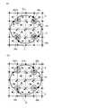
図48は、ブロックの形状が格子状以外であるブロックにおいて、方向を定義したものである。 FIG. 48 defines the direction in a block whose block shape is other than a lattice shape.
同図において、まず基準点48a〜48eが配置されている。この基準点48a〜48eを結ぶ線によってブロックの向きを示す形状(ここでは上方を向いた5角形)が定義されている。そして、この基準点に基づいて仮想基準点48f,48g,48hが配置され、この仮想基準点を視点始点として方向と長さを有するベクトル終点に情報ドット3が配置されている。このように、同図では、ブロックの向きを基準点の配置の仕方によって定義することができる。そしてブロックの向きが定義されることによって、ブロック全体の大きさも定義されることになる。 In the figure,
なお、図48においては、基準点48a〜48eと情報ドット3は全て同一形状のもので説明したが、たとえば図57に示すように、基準点48a〜48eを情報ドット3よりも大きな形状としてもよい。また、この基準点48a〜48eと情報ドット3とは識別可能であればいかなる形状としてもよく、三角形、四角形それ以上の多角形であってもよい。 In FIG. 48, the
なお、図49は、図48に示したブロックを縦横方向に2個ずつ連結したものである。 Note that FIG. 49 is obtained by connecting two blocks shown in FIG. 48 in the vertical and horizontal directions.
図50および図51は、ブロックの形状を格子状、すなわち矩形領域とはせずに、一部の基準点と仮想基準点とを一致させた場合を示したものである。 FIG. 50 and FIG. 51 show a case where some reference points and virtual reference points are made to coincide with each other without making the block shape a lattice, that is, a rectangular region.
すなわち、図48において配置されている48a,48b,48c,48d,48e,48f,48gは、基準点であると同時に仮想基準点とみることができる。そのため図50では、各点を始点としたベクトルの終点に情報ドット3を配置している。そして、48a,48b,48c,48f,48gで構成される五角形において、48cが頂点であることから、当該ブロックが上向きであることが認識できる。 That is, 48a, 48b, 48c, 48d, 48e, 48f, and 48g arranged in FIG. 48 can be considered as virtual reference points as well as reference points. Therefore, in FIG. 50, the information dot 3 is arranged at the end point of the vector starting from each point. And in the pentagon comprised of 48a, 48b, 48c, 48f, and 48g, since 48c is a vertex, it can be recognized that the block is upward.
なお、図51は、図50に示したブロックを縦横方向に2個ずつ連結したものである。 Note that FIG. 51 is obtained by connecting two blocks shown in FIG. 50 in the vertical and horizontal directions.
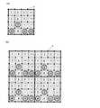
図52および図53は、他とは異なる方向基準で情報ドットを配置することにより、ブロックの方向を定義する場合を示している。 52 and 53 show a case where the direction of a block is defined by arranging information dots based on a direction reference different from others.
同図では、ブロックの四隅に基準点が配置されている。仮想基準点を中心に配置される情報ドット3のうち、ディレクション領域21aにおける情報ドット3の向きを、他の情報ドットの方向基準と異ならせることにより方向を定義する。すなわち、ディレクション領域21aのみ仮想基準点から縦横方向にずれた位置に情報ドット3を配置し、その他の領域では情報ドット3は仮想基準点から斜め方向にずれた位置に配置されている。図52では、ディレクション領域21aがブロック中心から上方にずれた位置(+Y方向)に配置されているので、当該ブロックは上向きであることがわかる。なお、このようにディレクション領域21aのブロック内の位置でブロックの方向を定義した場合には、ディレクション領域21a内の情報ドット3の配置は任意である。すなわち同図では、情報ドット3は、仮想基準点よりも右方向のベクトル終点に配置されている。 In the figure, reference points are arranged at the four corners of the block. Of the
図53は、図52に示したブロックを縦横方向に2個ずつ連結したものである。 FIG. 53 is obtained by connecting two blocks shown in FIG. 52 in the vertical and horizontal directions.
図54および図55は、複数の領域において、他とは異なる方向基準で情報ドットを配置することにより、ブロックの方向を定義する場合を示している。 54 and 55 show a case where the direction of a block is defined by arranging information dots in a plurality of areas based on a different direction reference from the others.
同図では、ブロックの四隅に基準点が配置されている。当該ブロックにおいて、仮想基準点を中心に配置される情報ドット3のうち、3カ所の情報ドット3の配置における方向基準を他の領域と異ならせることによって、この3カ所をディレクション領域21aとし、このディレクション領域21aを結ぶ線の形状でブロックの方向を定義したものである。すなわち同図では三角形の形状から当該ブロックが上向きであることが識別できる。 In the figure, reference points are arranged at the four corners of the block. In this block, among the
図55は、図54に示したブロックを縦横方向に2個ずつ連結したものである。 FIG. 55 is obtained by connecting two blocks shown in FIG. 54 in the vertical and horizontal directions.
図56は、基準点4aを格子点と一致させた場合であり、このようにブロック中心を基準に点対称とならないように基準点4aを配置した場合には、あえてディレクション領域やディレクションドットを配置することなく、そのままブロックの方向を定義することができる。 FIG. 56 shows a case where the
図57は図48に示したドットパターンの基準点48a〜48gのドットの大きさを他の情報ドット3よりも大きくしたものである。 FIG. 57 shows the dot size of the
なお、本実施形態では、情報ドット、ディレクションドット、基準ドットの各ドットは円形のものを用いて説明したが、これに限らず、非円形の三角形、四角形またはそれ以上の多角形であってもよいことはもちろんである。 In this embodiment, the information dots, the direction dots, and the reference dots have been described as being circular. However, the present invention is not limited to this, and the information dots, direction dots, and reference dots may be non-circular triangles, squares, or more polygons. Of course it is good.
なお、図58は、1カ所の基準ドット58aのみを他の基準ドット58b〜58dよりも大きなドットとすることで、この大形の基準ドット58aが配置された方向でブロックの方向を定義したものである。この基準ドット58aについても、形状や大きさを変更してもよいことは勿論である。また、基準ドット58aを配置しないことでブロックの方向を定義してもよい。また、このように大きさを変更したドットを配置してブロックの方向を定義する場合、当該ドットはかならずしも基準ドットである必要はなく、情報ドット3であってもよい。情報ドット3の大きさを変更することでブロックの方向を定義する場合には、情報ドット3の情報を犠牲にすることなくブロックの方向を定義することが可能となる。 In FIG. 58, only one
図59は、ディレクションドット21の大きさを他の情報ドット3または基準格子点ドット4よりも大きくすることで当該ドットがディレクションドット21であることを識別可能としたものである。このようにディレクションドット21の大きさを他の情報ドットと変えることによって、情報ドット3の方向基準がディレクションドット21の方向基準と同じであっても(図59では両者ともの縦横方向となっている)、ブロックの方向を定義することが可能となる。 FIG. 59 shows that the direction dot 21 can be identified as the direction dot 21 by making the size of the direction dot 21 larger than that of the
図62は、ブロックの中央上方の格子領域に情報ドットを配置しない構成を示している。このように所定の格子領域(仮想格子点上または基準点)に情報ドット3を配置しないことによってその格子領域の位置によってブロックの方向を定義することが可能となる。同図では、上向きのブロックであることがわかる。 FIG. 62 shows a configuration in which no information dot is arranged in the lattice area above the center of the block. Thus, by not arranging the
また、図63は、ブロックの中央上方の仮想格子点上に情報ドット3を配置することによってブロックの方向を定義した場合の例である。 FIG. 63 shows an example in which the direction of the block is defined by arranging the information dot 3 on the virtual lattice point above the center of the block.
図60は、格子領域内に配置される情報ドットの形状を複数の形状で表現したものである。同図に示すように、情報ドットの形状は、■、▲、●を選択的に配置しており、この形状毎に異なる情報を定義してもよい。 FIG. 60 expresses the shape of information dots arranged in the lattice area in a plurality of shapes. As shown in the figure, the shapes of information dots are selectively arranged as ■, ▲, and ●, and different information may be defined for each shape.
また、同図において、ブロックの方向は、四隅の基準格子点ドットのうちの2個を基準
格子点からずらして配置することによって定義することができる。同図ではブロックの左上と右上の基準格子点ドットを上方にずらしているため、当該ブロックは上向きであると識別できる。Also, in the same figure, the direction of the block can be defined by disposing two of the reference grid point dots at the four corners so as to be shifted from the reference grid point. In the figure, since the reference grid point dots at the upper left and upper right of the block are shifted upward, the block can be identified as facing upward.
図61は、ブロックの中央の格子領域の仮想格子点に配置される情報ドット3についてのみ他の情報ドットと形状を異ならせたものである。この仮想格子点には三角形の情報ドットが配置されており、当該三角形の形状によって、当該ブロックが上向きであることが認識できるようになっている。 In FIG. 61, only the information dot 3 arranged at the virtual lattice point in the lattice region at the center of the block is different from the other information dots in shape. Triangular information dots are arranged at the virtual lattice points, and the shape of the triangle makes it possible to recognize that the block is facing upward.
本発明は、光学センサで読み取ることによって音楽や音声を出力できる絵本、写真、カードゲーム、セキュリティシステム等に広く利用できる。 The present invention can be widely used for picture books, photographs, card games, security systems, and the like that can output music and audio by being read by an optical sensor.
1 ドットパターン
2 キードット
3 情報ドット
4 基準格子点ドット
7a〜7d 基準格子線
8a,8b 格子線
13 仮想格子点
21 ディレクションドット
28a,28b 横方向格子線
34a,34b,34c 格子領域
36a,36b,36c,36d 格子領域
387〜389,391〜393,394〜396 格子領域
401〜403,404〜406 格子領域
411 格子領域
441 格子領域1 dot
Claims (6)
Translated fromJapanese該基準点から定義される複数の仮想基準点を配置し、
前記仮想基準点からの距離と方向とで情報が定義される情報ドットを配置し、
前記少なくとも所定の位置の情報ドットを、前記仮想基準点からの方向で前記ブロックの向きを示すディレクションドットとしたドットパターン。A plurality of reference points are provided in a block area where predetermined information dots are arranged,
Arranging a plurality of virtual reference points defined from the reference points;
Arranging information dots whose information is defined by the distance and direction from the virtual reference point,
A dot pattern in which the information dots at the predetermined position are direction dots indicating the direction of the block in the direction from the virtual reference point.
前記4個の格子点の中心を前記仮想ベクトル始点とし、この仮想ベクトル始点を基準として、前記情報ドットは前記ディレクションドットを定義させるために必要な方向を除外した方向で情報が定義されている請求項1記載のドットパターン。The reference points are lattice points arranged at equal intervals in the vertical and horizontal directions within the area of the block,
The center of the four grid points is set as the virtual vector start point, and the information dot is defined in a direction excluding a direction necessary for defining the direction dot with reference to the virtual vector start point. Item 2. The dot pattern according to Item 1.
この仮想ベクトル始点を基準として、前記情報ドットが配置されているか否かで情報の意味づけがされている請求項1記載のドットパターン。The reference points are provided with vertical and horizontal reference grid lines in the area of the block, and virtual grid points provided at predetermined intervals on the vertical or horizontal reference grid lines are used as the virtual vector start points.
The dot pattern according to claim 1, wherein information is given meaning based on whether or not the information dot is arranged with reference to the virtual vector start point.
この仮想ベクトル始点を基準として、前記情報ドットは前記ディレクションドットを定義させるために必要な方向を除外した方向で情報が定義されている請求項1記載のドットパターン。The reference points are provided with vertical and horizontal reference grid lines in the block area, virtual grid points are provided at predetermined intervals on the reference grid lines, and virtual points provided on the horizontal reference grid lines are provided. place the reference grid point dot on a grid point, the reference grid point dots andthe line joining the virtual grid points to each other as a grid line, and an intersection of grid lines between the virtual vector start point,
2. The dot pattern according to claim 1, wherein the information dot is defined in a direction excluding a direction necessary for defining the direction dot with reference to the virtual vector start point.
In the block, the information dot at a predetermined position is set as a direction dot, and information dots other than the direction dot on the horizontal grid line where the direction dot is arranged and the central horizontal grid line of the block are symmetrical. 6. The dot pattern according to claim 5, wherein information dots that aresymmetrical withrespect to the direction dots as axes have information defined by directions or distances excluding directions necessary for defining the direction dots.
Priority Applications (20)
| Application Number | Priority Date | Filing Date | Title |
|---|---|---|---|
| JP2005194295AJP3771252B1 (en) | 2005-07-01 | 2005-07-01 | Dot pattern |
| TW95123589ATWI446279B (en) | 2005-07-01 | 2006-06-29 | Dot pattern |
| TW105117035ATWI618000B (en) | 2005-07-01 | 2006-06-29 | Dot pattern (3) |
| TW103119047ATWI550528B (en) | 2005-07-01 | 2006-06-29 | Dot pattern |
| MYPI20063148AMY164588A (en) | 2005-07-01 | 2006-06-30 | Dot pattern |
| AU2006266517AAU2006266517B2 (en) | 2005-07-01 | 2006-06-30 | Dot pattern |
| CN2006800235674ACN101213564B (en) | 2005-07-01 | 2006-06-30 | Dot pattern |
| RU2008102706ARU2439699C2 (en) | 2005-07-01 | 2006-06-30 | Dot structure |
| US11/993,527US8430328B2 (en) | 2005-07-01 | 2006-06-30 | Dot pattern |
| PCT/SG2006/000185WO2007004994A1 (en) | 2005-07-01 | 2006-06-30 | Dot pattern |
| BRPI0612755-0ABRPI0612755B1 (en) | 2005-07-01 | 2006-06-30 | dot pattern |
| KR1020077024724AKR100935345B1 (en) | 2005-07-01 | 2006-06-30 | Dot pattern |
| EP06748126.7AEP1899900B1 (en) | 2005-07-01 | 2006-06-30 | Dot pattern |
| EP11175120.2AEP2439677B1 (en) | 2005-07-01 | 2006-06-30 | Dot pattern reading and generating devices |
| CN201210025984.XACN102722267B (en) | 2005-07-01 | 2006-06-30 | Dot pattern |
| MX2007016474AMX352384B (en) | 2005-07-01 | 2006-06-30 | Dot pattern. |
| CA2613046ACA2613046C (en) | 2005-07-01 | 2006-06-30 | Dot pattern |
| IL188225AIL188225A (en) | 2005-07-01 | 2007-12-18 | Dot pattern |
| US13/872,555US9400951B2 (en) | 2005-07-01 | 2013-04-29 | Dot pattern |
| US15/218,841US20160335528A1 (en) | 2005-07-01 | 2016-07-25 | Dot pattern |
Applications Claiming Priority (1)
| Application Number | Priority Date | Filing Date | Title |
|---|---|---|---|
| JP2005194295AJP3771252B1 (en) | 2005-07-01 | 2005-07-01 | Dot pattern |
Related Child Applications (1)
| Application Number | Title | Priority Date | Filing Date |
|---|---|---|---|
| JP2005334219ADivisionJP4142683B2 (en) | 2005-11-18 | 2005-11-18 | Dot pattern |
Publications (2)
| Publication Number | Publication Date |
|---|---|
| JP3771252B1true JP3771252B1 (en) | 2006-04-26 |
| JP2007011890A JP2007011890A (en) | 2007-01-18 |
Family
ID=36383733
Family Applications (1)
| Application Number | Title | Priority Date | Filing Date |
|---|---|---|---|
| JP2005194295AExpired - LifetimeJP3771252B1 (en) | 2005-07-01 | 2005-07-01 | Dot pattern |
Country Status (14)
| Country | Link |
|---|---|
| US (3) | US8430328B2 (en) |
| EP (2) | EP2439677B1 (en) |
| JP (1) | JP3771252B1 (en) |
| KR (1) | KR100935345B1 (en) |
| CN (2) | CN101213564B (en) |
| AU (1) | AU2006266517B2 (en) |
| BR (1) | BRPI0612755B1 (en) |
| CA (1) | CA2613046C (en) |
| IL (1) | IL188225A (en) |
| MX (1) | MX352384B (en) |
| MY (1) | MY164588A (en) |
| RU (1) | RU2439699C2 (en) |
| TW (3) | TWI618000B (en) |
| WO (1) | WO2007004994A1 (en) |
Cited By (8)
| Publication number | Priority date | Publication date | Assignee | Title |
|---|---|---|---|---|
| JP2009540473A (en)* | 2006-06-14 | 2009-11-19 | ヒューレット−パッカード デベロップメント カンパニー エル.ピー. | Location using error correction |
| WO2010007787A1 (en) | 2008-07-15 | 2010-01-21 | Yoshida Kenji | Naked eye three-dimensional video image display system, naked eye three-dimensional video image display device, amusement game machine and parallax barrier sheet |
| JP2011053854A (en)* | 2009-09-01 | 2011-03-17 | Hong-Teng Lv | Coding method of two-dimensional optical recognition code and print product using the method |
| WO2011059002A1 (en) | 2009-11-11 | 2011-05-19 | Yoshida Kenji | Printing medium, information processing method, information processing device |
| WO2012077766A2 (en) | 2010-12-09 | 2012-06-14 | Yoshida Kenji | Display format using display device for machine-readable dot patterns |
| WO2014054647A1 (en) | 2012-10-01 | 2014-04-10 | Yoshida Kenji | Dot pattern, dot-pattern-forming medium, program for generating image data for dot pattern, dot pattern forming apparatus, optical device, optical device reader, information i/o device, dot pattern reader |
| WO2014088081A1 (en) | 2012-12-05 | 2014-06-12 | Yoshida Kenji | Facility-management-system control interface |
| JP5685677B2 (en)* | 2012-05-09 | 2015-03-18 | 株式会社アポロジャパン | Method of generating information embedding code for mobile phone, information embedding method, and reading method thereof |
Families Citing this family (44)
| Publication number | Priority date | Publication date | Assignee | Title |
|---|---|---|---|---|
| MXPA05003310A (en) | 2002-09-26 | 2005-10-18 | Yoshida Kenji | Information reproduction/i/o method using dot pattern, information reproduction device, mobile information i/o device, and electronic toy. |
| US8237983B2 (en)* | 2004-12-28 | 2012-08-07 | Kenji Yoshida | Information input output method using dot pattern |
| CA2606135C (en) | 2005-04-28 | 2015-06-30 | Kenji Yoshida | Information input/output method using dot pattern |
| JP3771252B1 (en)* | 2005-07-01 | 2006-04-26 | 健治 吉田 | Dot pattern |
| JP3830956B1 (en)* | 2005-09-14 | 2006-10-11 | 健治 吉田 | Information output device |
| EP1983412A4 (en)* | 2006-01-31 | 2011-07-20 | Kenji Yoshida | Image processing method |
| TWI370413B (en) | 2006-04-14 | 2012-08-11 | Sonix Technology Co Ltd | Graphical indicator |
| US20080252916A1 (en)* | 2007-04-13 | 2008-10-16 | Etoms Electronics Corp. | Information reproduction method and device using dot pattern and dot pattern thereof |
| CN101849243B (en)* | 2007-10-30 | 2014-05-28 | 吉田健治 | Code pattern |
| AU2007254595B2 (en)* | 2007-12-20 | 2011-04-07 | Canon Kabushiki Kaisha | Constellation detection |
| DE102008017168A1 (en)* | 2008-04-02 | 2009-10-08 | Crossmedia Solution Gmbh & Co. Kg | Method for storing and reading data |
| KR100968255B1 (en) | 2008-07-01 | 2010-07-06 | 이병진 | Contact card recognition system and recognition method using touch screen |
| TWI397013B (en)* | 2008-09-26 | 2013-05-21 | Elan Microelectronics Corp | The dot code pattern and the dot code group pattern and the image processing circuit of the density coding type |
| CN101727596B (en)* | 2008-10-13 | 2013-09-18 | 义隆电子股份有限公司 | Dot code pattern and image processing device for processing dot code pattern |
| CN101727595B (en)* | 2008-10-13 | 2012-09-26 | 义隆电子股份有限公司 | Dot code pattern and dot code group pattern and its image processing circuit |
| US9010640B2 (en) | 2009-07-13 | 2015-04-21 | Kenji Yoshida | Stream dot pattern, method of forming stream dot pattern, information input/output method using stream dot pattern, and dot pattern |
| US9749607B2 (en) | 2009-07-16 | 2017-08-29 | Digimarc Corporation | Coordinated illumination and image signal capture for enhanced signal detection |
| US8218004B2 (en)* | 2009-10-22 | 2012-07-10 | Cycling & Health Tech Industry R&D Center | Displacement sensing system |
| KR100991878B1 (en)* | 2009-10-22 | 2010-11-04 | 장효선 | Code decoding method being indicated on printed object |
| JP5277403B2 (en)* | 2010-01-06 | 2013-08-28 | 健治 吉田 | Curved body for information input, map for information input, drawing for information input |
| TWI439943B (en)* | 2010-04-27 | 2014-06-01 | Shou Te Wei | Encoding structure for dot pattern, its decoding method and electronic device |
| US9576230B2 (en)* | 2010-07-06 | 2017-02-21 | Marcelo Amaral Rezende | Dot code pattern for absolute position and other information using an optical pen, process of printing the dot code, process of reading the dot code |
| WO2013027234A1 (en)* | 2011-08-22 | 2013-02-28 | Zak株式会社 | Satellite dot type two-dimensional code and method for reading same |
| TWI489352B (en)* | 2013-08-13 | 2015-06-21 | Wistron Corp | Optical touch positioning method, system and optical touch positioner |
| US9635378B2 (en) | 2015-03-20 | 2017-04-25 | Digimarc Corporation | Sparse modulation for robust signaling and synchronization |
| US10424038B2 (en) | 2015-03-20 | 2019-09-24 | Digimarc Corporation | Signal encoding outside of guard band region surrounding text characters, including varying encoding strength |
| TWI492167B (en) | 2014-06-05 | 2015-07-11 | Sonix Technology Co Ltd | Graphical indicator |
| EP3045214A1 (en) | 2015-01-14 | 2016-07-20 | Cartamundi Turnhout N.V. | Board game with pattern recognition |
| US10783601B1 (en) | 2015-03-20 | 2020-09-22 | Digimarc Corporation | Digital watermarking and signal encoding with activable compositions |
| WO2016153936A1 (en) | 2015-03-20 | 2016-09-29 | Digimarc Corporation | Digital watermarking and data hiding with narrow-band absorption materials |
| ES2724010T3 (en)* | 2015-04-30 | 2019-09-05 | Nestle Sa | Code and system container for preparing a beverage or food |
| WO2017007483A1 (en)* | 2015-07-09 | 2017-01-12 | Hewlett-Packard Development Company, L.P. | Multi-dimensional cyclic symbols |
| TWI545504B (en) | 2015-08-31 | 2016-08-11 | 原相科技股份有限公司 | Decoding method using patterns and system thereof |
| US9600700B1 (en) | 2015-08-31 | 2017-03-21 | Pixart Imaging Inc. | Portable electronic device and operation method thereof |
| US9805239B2 (en) | 2015-08-31 | 2017-10-31 | Pixart Imagine Inc. | QR code detecting device and operation method thereof |
| CN109359657B (en) | 2015-10-19 | 2022-11-25 | 松翰科技股份有限公司 | Index structure |
| US10896307B2 (en) | 2017-11-07 | 2021-01-19 | Digimarc Corporation | Generating and reading optical codes with variable density to adapt for visual quality and reliability |
| US11062108B2 (en) | 2017-11-07 | 2021-07-13 | Digimarc Corporation | Generating and reading optical codes with variable density to adapt for visual quality and reliability |
| US10872392B2 (en) | 2017-11-07 | 2020-12-22 | Digimarc Corporation | Generating artistic designs encoded with robust, machine-readable data |
| KR102066391B1 (en)* | 2017-11-16 | 2020-01-15 | 상명대학교산학협력단 | Data embedding appratus for multidimensional symbology system based on 3-dimension and data embedding method for the symbology system |
| KR102104027B1 (en)* | 2018-08-30 | 2020-04-23 | 선문대학교 산학협력단 | Mesh structure indicating information and touch device having sensing electrode made of the mesh structure |
| US20220398769A1 (en)* | 2019-10-31 | 2022-12-15 | Hewlett-Packard Development Company, L.P. | Recovering alignment grids |
| KR102450872B1 (en)* | 2020-10-05 | 2022-10-05 | 에르미 주식회사 | Dot pattern and method for recognizing dot pattern |
| US12361248B2 (en) | 2023-05-19 | 2025-07-15 | Aires Investment Holdings Private Limited | Two-dimensional code and method and system for generating and reading thereof |
Family Cites Families (93)
| Publication number | Priority date | Publication date | Assignee | Title |
|---|---|---|---|---|
| US4263504A (en) | 1979-08-01 | 1981-04-21 | Ncr Corporation | High density matrix code |
| US4604065A (en) | 1982-10-25 | 1986-08-05 | Price/Stern/Sloan Publishers, Inc. | Teaching or amusement apparatus |
| JPS6165213A (en) | 1984-09-06 | 1986-04-03 | Canon Inc | Optical system for autofocus |
| US4627819A (en) | 1985-01-23 | 1986-12-09 | Price/Stern/Sloan Publishers, Inc. | Teaching or amusement apparatus |
| US4924078A (en) | 1987-11-25 | 1990-05-08 | Sant Anselmo Carl | Identification symbol, system and method |
| US5124536A (en) | 1988-05-05 | 1992-06-23 | International Data Matrix, Inc. | Dynamically variable machine readable binary code and method for reading and producing thereof |
| US4939354A (en) | 1988-05-05 | 1990-07-03 | Datacode International, Inc. | Dynamically variable machine readable binary code and method for reading and producing thereof |
| US5591957A (en) | 1988-08-12 | 1997-01-07 | Casio Computer Co., Ltd. | Apparatus for reading mesh pattern image data having bars along upper and lower sides of mesh pattern and a boundary line between horizontally adjacent dark and light area of mesh pattern |
| US5042079A (en) | 1988-08-12 | 1991-08-20 | Casio Computer Co., Ltd. | Method of recording/reproducing data of mesh pattern, and apparatus therefor |
| US5051736A (en) | 1989-06-28 | 1991-09-24 | International Business Machines Corporation | Optical stylus and passive digitizing tablet data input system |
| US5128528A (en)* | 1990-10-15 | 1992-07-07 | Dittler Brothers, Inc. | Matrix encoding devices and methods |
| FR2684214B1 (en) | 1991-11-22 | 1997-04-04 | Sepro Robotique | INDEXING CARD FOR GEOGRAPHIC INFORMATION SYSTEM AND SYSTEM INCLUDING APPLICATION. |
| US5852434A (en) | 1992-04-03 | 1998-12-22 | Sekendur; Oral F. | Absolute optical position determination |
| JPH10187907A (en) | 1992-09-28 | 1998-07-21 | Olympus Optical Co Ltd | Dot code |
| AU668987B2 (en) | 1992-09-28 | 1996-05-23 | Olympus Optical Co., Ltd. | Dot code and information recording/reproducing system for recording/reproducing dot code |
| US5416312A (en) | 1992-11-20 | 1995-05-16 | Cherloc | Document bearing an image or a text and provided with an indexing frame, and associated document analysis system |
| RU2126598C1 (en) | 1993-11-16 | 1999-02-20 | Кузнецов Юрий Вениаминович | Method and device for adaptive rendering of half-tone images |
| JP3277052B2 (en) | 1993-11-19 | 2002-04-22 | シャープ株式会社 | Coordinate input device and coordinate input method |
| JPH07178257A (en) | 1993-12-24 | 1995-07-18 | Casio Comput Co Ltd | Audio output device |
| JPH07296387A (en) | 1994-04-22 | 1995-11-10 | Olympus Optical Co Ltd | Information recording medium |
| JPH0837567A (en) | 1994-07-26 | 1996-02-06 | Olympus Optical Co Ltd | Information recording medium and information reproducing device |
| JP2912831B2 (en) | 1994-10-05 | 1999-06-28 | オリンパス光学工業株式会社 | Information recording medium and information reproducing apparatus |
| JP3639328B2 (en)* | 1994-10-14 | 2005-04-20 | オリンパス株式会社 | Information recording medium, two-dimensional code, information reproducing system, and information reproducing method |
| US5661506A (en) | 1994-11-10 | 1997-08-26 | Sia Technology Corporation | Pen and paper information recording system using an imaging pen |
| JP2952170B2 (en) | 1994-12-16 | 1999-09-20 | オリンパス光学工業株式会社 | Information reproduction system |
| TW331000B (en)* | 1994-12-28 | 1998-05-01 | Eten Information System Co Ltd | Method for determining crossing points of two overlapping figures |
| JP3523710B2 (en) | 1995-04-04 | 2004-04-26 | オリンパス株式会社 | Information reproduction system, recording medium, recording device, and recording method |
| GB9507098D0 (en) | 1995-04-06 | 1995-05-31 | Rolls Royce Plc | Process and apparatus for reading a dot matrix code marking of an article |
| JPH0944591A (en) | 1995-08-03 | 1997-02-14 | Olympus Optical Co Ltd | Code sheet and information reproducing device |
| JPH09114951A (en) | 1995-10-23 | 1997-05-02 | Olympus Optical Co Ltd | Information recording medium |
| JPH09185488A (en) | 1995-12-27 | 1997-07-15 | Tetsuya Fuchiguchi | Multimedia doll system |
| JP3956419B2 (en) | 1997-03-06 | 2007-08-08 | 凸版印刷株式会社 | ID card creation method, ID card and ID card information reading method |
| JPH10326331A (en)* | 1997-03-24 | 1998-12-08 | Olympus Optical Co Ltd | Recording medium with dot code, and code reader |
| JPH10326323A (en) | 1997-03-24 | 1998-12-08 | Olympus Optical Co Ltd | Code pattern image recording device |
| US6012961A (en) | 1997-05-14 | 2000-01-11 | Design Lab, Llc | Electronic toy including a reprogrammable data storage device |
| JPH10320497A (en) | 1997-05-16 | 1998-12-04 | Olympus Optical Co Ltd | Code reading and recording device |
| JP3953144B2 (en) | 1997-07-16 | 2007-08-08 | オリンパス株式会社 | Code image quality inspection system |
| EP0921675B1 (en) | 1997-12-03 | 2006-07-05 | Kabushiki Kaisha Toshiba | Method of processing image information and method of preventing forgery of certificates or the like |
| JP3959817B2 (en) | 1998-01-07 | 2007-08-15 | 富士ゼロックス株式会社 | Image forming apparatus |
| JPH11219405A (en) | 1998-02-02 | 1999-08-10 | Olympus Optical Co Ltd | Information reproducing system |
| WO1999050736A1 (en) | 1998-04-01 | 1999-10-07 | Xerox Corporation | Paper indexing of recordings |
| JP3458737B2 (en) | 1998-11-27 | 2003-10-20 | 株式会社デンソー | Reading method of two-dimensional code and recording medium |
| JP2000285225A (en) | 1999-03-30 | 2000-10-13 | Kiyoyuki Horii | Method for processing image by computer |
| RU2166207C2 (en) | 1999-04-08 | 2001-04-27 | Закрытое акционерное общество "Аби Программное обеспечение" | Method for using auxiliary data arrays in conversion and/or verification of character-expressed computer codes and respective subpictures |
| GB2349836A (en) | 1999-04-23 | 2000-11-15 | Tri State | Talking doll with bar-code optical reader |
| JP2000325668A (en) | 1999-05-14 | 2000-11-28 | T Shot:Kk | Reactive talking toy system |
| AUPQ363299A0 (en) | 1999-10-25 | 1999-11-18 | Silverbrook Research Pty Ltd | Paper based information inter face |
| US6728000B1 (en) | 1999-05-25 | 2004-04-27 | Silverbrook Research Pty Ltd | Method and system for printing a document |
| US6830196B1 (en) | 1999-05-25 | 2004-12-14 | Silverbrook Research Pty Ltd | Identity-coded surface region |
| JP4785310B2 (en) | 1999-05-28 | 2011-10-05 | アノト アクティエボラーク | Products used to record information |
| JP3764100B2 (en) | 1999-05-28 | 2006-04-05 | アノト アイ ピー リック エイチ ビー | Calendar book |
| EP1188142A1 (en) | 1999-05-28 | 2002-03-20 | Anoto AB | Recording of information |
| SE516522C2 (en) | 1999-05-28 | 2002-01-22 | Anoto Ab | Position determining product for digitization of drawings or handwritten information, obtains displacement between symbol strings along symbol rows when symbol strings are repeated on symbol rows |
| JP2001052104A (en) | 1999-08-05 | 2001-02-23 | Olympus Optical Co Ltd | Data recording method, data reproducing method and data recording medium |
| SE0000939L (en) | 2000-02-18 | 2001-08-19 | Anoto Ab | Inenhetsarrangemang |
| US6533182B1 (en)* | 1999-09-21 | 2003-03-18 | Omron Corporation | Two-dimensional dot code and reader thereof |
| SE517445C2 (en) | 1999-10-01 | 2002-06-04 | Anoto Ab | Position determination on a surface provided with a position coding pattern |
| MXPA02006340A (en) | 1999-12-23 | 2002-12-13 | Anoto Ab | General information management system. |
| US6244764B1 (en) | 2000-01-21 | 2001-06-12 | Robotic Vision Systems, Inc. | Method for data matrix print quality verification |
| WO2001059643A1 (en) | 2000-02-10 | 2001-08-16 | Sony Corporation | Automatic device, information providing device, robot device, and transaction method |
| US7050653B2 (en) | 2000-04-05 | 2006-05-23 | Anoto Ab | Identification of virtual raster pattern |
| US6586688B2 (en) | 2000-04-05 | 2003-07-01 | Anoto Ab | Information-related devices and methods |
| JP2001287330A (en) | 2000-04-10 | 2001-10-16 | Olympus Optical Co Ltd | Method and apparatus for forming image data of optically readable dots and recording medium |
| JP2001318926A (en) | 2000-05-11 | 2001-11-16 | Yazaki Corp | Information management device and information management system using the device |
| JP2002041199A (en) | 2000-05-15 | 2002-02-08 | Pasukaru:Kk | Operation processing method for computer device using shortcut symbol, and shortcut processing system |
| JP2001334012A (en) | 2000-05-29 | 2001-12-04 | Creatures Inc | Game system using game card, game card used therefor, and game information storage medium used therefor |
| JP3837999B2 (en) | 2000-06-05 | 2006-10-25 | 富士ゼロックス株式会社 | Image generation method and image generation apparatus |
| JP2002002024A (en) | 2000-06-26 | 2002-01-08 | Olympus Optical Co Ltd | Method and apparatus for printing code and recording medium |
| AU2001284468A1 (en) | 2000-09-12 | 2002-03-26 | Omron Corporation | Dot code and dot code reader |
| JP4567860B2 (en) | 2000-09-12 | 2010-10-20 | 任天堂株式会社 | Code reader, recording medium, electronic device, data transmission / reception system, and data transmission / reception method |
| JP2002205291A (en) | 2000-10-23 | 2002-07-23 | Sony Corp | Leg type robot and movement control method for leg type robot, as well as recording medium |
| JP2002149331A (en) | 2000-11-15 | 2002-05-24 | Canon Inc | Coordinate plate, coordinate input device, coordinate input / output device |
| US6633008B2 (en) | 2001-02-27 | 2003-10-14 | Weigh-Tronix, Inc. | Electronic force sensing shock resistant load cell |
| JP4763905B2 (en) | 2001-03-06 | 2011-08-31 | オリンパス株式会社 | Encoded image reader |
| US7649637B2 (en) | 2001-04-05 | 2010-01-19 | Anoto Ab | Method for printing a global position-coding pattern |
| US6732927B2 (en) | 2001-06-26 | 2004-05-11 | Anoto Ab | Method and device for data decoding |
| SE520682C2 (en) | 2001-12-06 | 2003-08-12 | Anoto Ab | Reconstruction of a virtual screen |
| TWI235926B (en) | 2002-01-11 | 2005-07-11 | Sonix Technology Co Ltd | A method for producing indicators and processing system, coordinate positioning system and electronic book system utilizing the indicators |
| MXPA05003310A (en)* | 2002-09-26 | 2005-10-18 | Yoshida Kenji | Information reproduction/i/o method using dot pattern, information reproduction device, mobile information i/o device, and electronic toy. |
| SE0203853D0 (en) | 2002-12-23 | 2002-12-23 | Anoto Ab | Data code |
| CN100361144C (en) | 2003-03-17 | 2008-01-09 | 吉田健治 | Information input/output method using dot pattern |
| JP3902163B2 (en) | 2003-07-11 | 2007-04-04 | 大日本印刷株式会社 | Related form determination system, electronic pen and program |
| JP4200106B2 (en) | 2003-07-15 | 2008-12-24 | 株式会社リコー | Image processing apparatus, image processing method, computer program, and storage medium for storing computer program |
| AU2003292817A1 (en) | 2003-12-25 | 2005-07-21 | Kenji Yoshida | Method for inputting/outputting information using dot pattern |
| US8237983B2 (en) | 2004-12-28 | 2012-08-07 | Kenji Yoshida | Information input output method using dot pattern |
| JPWO2006112021A1 (en) | 2005-04-15 | 2008-11-27 | 吉田 健治 | Information input / output method using dot pattern |
| CA2606135C (en) | 2005-04-28 | 2015-06-30 | Kenji Yoshida | Information input/output method using dot pattern |
| JP3771252B1 (en) | 2005-07-01 | 2006-04-26 | 健治 吉田 | Dot pattern |
| JP4810918B2 (en) | 2005-08-01 | 2011-11-09 | 富士ゼロックス株式会社 | Code pattern image generating apparatus and method, code pattern image reading apparatus and method, and code pattern image medium |
| AU2006252254B2 (en) | 2006-12-22 | 2009-03-05 | Canon Kabushiki Kaisha | Multiple barcode detection |
| AU2006252239B2 (en) | 2006-12-22 | 2010-04-01 | Canon Kabushiki Kaisha | Barcode pattern |
| US20080252916A1 (en) | 2007-04-13 | 2008-10-16 | Etoms Electronics Corp. | Information reproduction method and device using dot pattern and dot pattern thereof |
| TWI391862B (en)* | 2008-06-06 | 2013-04-01 | Elan Microelectronics Corp | A two-dimensional dot code, a decoding apparatus, and a method thereof |
- 2005
- 2005-07-01JPJP2005194295Apatent/JP3771252B1/ennot_activeExpired - Lifetime
- 2006
- 2006-06-29TWTW105117035Apatent/TWI618000B/ennot_activeIP Right Cessation
- 2006-06-29TWTW95123589Apatent/TWI446279B/ennot_activeIP Right Cessation
- 2006-06-29TWTW103119047Apatent/TWI550528B/ennot_activeIP Right Cessation
- 2006-06-30MYMYPI20063148Apatent/MY164588A/enunknown
- 2006-06-30MXMX2007016474Apatent/MX352384B/enactiveIP Right Grant
- 2006-06-30EPEP11175120.2Apatent/EP2439677B1/ennot_activeNot-in-force
- 2006-06-30KRKR1020077024724Apatent/KR100935345B1/ennot_activeExpired - Fee Related
- 2006-06-30CNCN2006800235674Apatent/CN101213564B/ennot_activeExpired - Fee Related
- 2006-06-30RURU2008102706Apatent/RU2439699C2/ennot_activeIP Right Cessation
- 2006-06-30WOPCT/SG2006/000185patent/WO2007004994A1/enactiveApplication Filing
- 2006-06-30CNCN201210025984.XApatent/CN102722267B/ennot_activeExpired - Fee Related
- 2006-06-30BRBRPI0612755-0Apatent/BRPI0612755B1/ennot_activeIP Right Cessation
- 2006-06-30USUS11/993,527patent/US8430328B2/ennot_activeExpired - Fee Related
- 2006-06-30EPEP06748126.7Apatent/EP1899900B1/ennot_activeRevoked
- 2006-06-30CACA2613046Apatent/CA2613046C/ennot_activeExpired - Fee Related
- 2006-06-30AUAU2006266517Apatent/AU2006266517B2/ennot_activeCeased
- 2007
- 2007-12-18ILIL188225Apatent/IL188225A/ennot_activeIP Right Cessation
- 2013
- 2013-04-29USUS13/872,555patent/US9400951B2/ennot_activeExpired - Fee Related
- 2016
- 2016-07-25USUS15/218,841patent/US20160335528A1/ennot_activeAbandoned
Cited By (10)
| Publication number | Priority date | Publication date | Assignee | Title |
|---|---|---|---|---|
| JP2009540473A (en)* | 2006-06-14 | 2009-11-19 | ヒューレット−パッカード デベロップメント カンパニー エル.ピー. | Location using error correction |
| WO2010007787A1 (en) | 2008-07-15 | 2010-01-21 | Yoshida Kenji | Naked eye three-dimensional video image display system, naked eye three-dimensional video image display device, amusement game machine and parallax barrier sheet |
| JP2011053854A (en)* | 2009-09-01 | 2011-03-17 | Hong-Teng Lv | Coding method of two-dimensional optical recognition code and print product using the method |
| WO2011059002A1 (en) | 2009-11-11 | 2011-05-19 | Yoshida Kenji | Printing medium, information processing method, information processing device |
| WO2012077766A2 (en) | 2010-12-09 | 2012-06-14 | Yoshida Kenji | Display format using display device for machine-readable dot patterns |
| KR20130143101A (en) | 2010-12-09 | 2013-12-30 | 켄지 요시다 | Display format using display device for machine-readable dot patterns |
| US9626934B2 (en) | 2010-12-09 | 2017-04-18 | Kenji Yoshida | Display format using display device for machine-readable dot patterns |
| JP5685677B2 (en)* | 2012-05-09 | 2015-03-18 | 株式会社アポロジャパン | Method of generating information embedding code for mobile phone, information embedding method, and reading method thereof |
| WO2014054647A1 (en) | 2012-10-01 | 2014-04-10 | Yoshida Kenji | Dot pattern, dot-pattern-forming medium, program for generating image data for dot pattern, dot pattern forming apparatus, optical device, optical device reader, information i/o device, dot pattern reader |
| WO2014088081A1 (en) | 2012-12-05 | 2014-06-12 | Yoshida Kenji | Facility-management-system control interface |
Also Published As
Similar Documents
| Publication | Publication Date | Title |
|---|---|---|
| JP3771252B1 (en) | Dot pattern | |
| AU2005331401B2 (en) | Information input/output method using dot pattern | |
| JP3706385B2 (en) | Information input / output method using dot pattern | |
| JP4336837B2 (en) | Dot pattern | |
| JP4142683B2 (en) | Dot pattern | |
| WO2006112021A1 (en) | Information i/o method using dot pattern | |
| JP3858051B6 (en) | Information input / output method using dot pattern | |
| HK1176418A (en) | Dot pattern | |
| CN101872411A (en) | Encoding method, decoding method, and encoding and decoding method of microcode array | |
| HK1176418B (en) | Dot pattern | |
| AU2016200846A1 (en) | Printed Material Printed with a Dot Pattern | |
| AU2012204140A1 (en) | Dot pattern |
Legal Events
| Date | Code | Title | Description |
|---|---|---|---|
| TRDD | Decision of grant or rejection written | ||
| A01 | Written decision to grant a patent or to grant a registration (utility model) | Free format text:JAPANESE INTERMEDIATE CODE: A01 Effective date:20060124 | |
| A61 | First payment of annual fees (during grant procedure) | Free format text:JAPANESE INTERMEDIATE CODE: A61 Effective date:20060208 | |
| R150 | Certificate of patent or registration of utility model | Ref document number:3771252 Country of ref document:JP Free format text:JAPANESE INTERMEDIATE CODE: R150 Free format text:JAPANESE INTERMEDIATE CODE: R150 | |
| FPAY | Renewal fee payment (event date is renewal date of database) | Free format text:PAYMENT UNTIL: 20090217 Year of fee payment:3 | |
| S201 | Request for registration of exclusive licence | Free format text:JAPANESE INTERMEDIATE CODE: R314201 | |
| FPAY | Renewal fee payment (event date is renewal date of database) | Free format text:PAYMENT UNTIL: 20090217 Year of fee payment:3 | |
| R350 | Written notification of registration of transfer | Free format text:JAPANESE INTERMEDIATE CODE: R350 | |
| FPAY | Renewal fee payment (event date is renewal date of database) | Free format text:PAYMENT UNTIL: 20090217 Year of fee payment:3 | |
| FPAY | Renewal fee payment (event date is renewal date of database) | Free format text:PAYMENT UNTIL: 20120217 Year of fee payment:6 | |
| R250 | Receipt of annual fees | Free format text:JAPANESE INTERMEDIATE CODE: R250 | |
| FPAY | Renewal fee payment (event date is renewal date of database) | Free format text:PAYMENT UNTIL: 20150217 Year of fee payment:9 | |
| R250 | Receipt of annual fees | Free format text:JAPANESE INTERMEDIATE CODE: R250 | |
| FPAY | Renewal fee payment (event date is renewal date of database) | Free format text:PAYMENT UNTIL: 20150217 Year of fee payment:9 | |
| FPAY | Renewal fee payment (event date is renewal date of database) | Free format text:PAYMENT UNTIL: 20150217 Year of fee payment:9 | |
| FPAY | Renewal fee payment (event date is renewal date of database) | Free format text:PAYMENT UNTIL: 20150217 Year of fee payment:9 | |
| S533 | Written request for registration of change of name | Free format text:JAPANESE INTERMEDIATE CODE: R314533 | |
| FPAY | Renewal fee payment (event date is renewal date of database) | Free format text:PAYMENT UNTIL: 20150217 Year of fee payment:9 | |
| R350 | Written notification of registration of transfer | Free format text:JAPANESE INTERMEDIATE CODE: R350 | |
| S111 | Request for change of ownership or part of ownership | Free format text:JAPANESE INTERMEDIATE CODE: R313113 | |
| S533 | Written request for registration of change of name | Free format text:JAPANESE INTERMEDIATE CODE: R314533 | |
| R350 | Written notification of registration of transfer | Free format text:JAPANESE INTERMEDIATE CODE: R350 | |
| R250 | Receipt of annual fees | Free format text:JAPANESE INTERMEDIATE CODE: R250 | |
| R250 | Receipt of annual fees | Free format text:JAPANESE INTERMEDIATE CODE: R250 | |
| R250 | Receipt of annual fees | Free format text:JAPANESE INTERMEDIATE CODE: R250 | |
| R250 | Receipt of annual fees | Free format text:JAPANESE INTERMEDIATE CODE: R250 | |
| S531 | Written request for registration of change of domicile | Free format text:JAPANESE INTERMEDIATE CODE: R313531 | |
| R350 | Written notification of registration of transfer | Free format text:JAPANESE INTERMEDIATE CODE: R350 | |
| R250 | Receipt of annual fees | Free format text:JAPANESE INTERMEDIATE CODE: R250 | |
| R250 | Receipt of annual fees | Free format text:JAPANESE INTERMEDIATE CODE: R250 | |
| R250 | Receipt of annual fees | Free format text:JAPANESE INTERMEDIATE CODE: R250 | |
| R250 | Receipt of annual fees | Free format text:JAPANESE INTERMEDIATE CODE: R250 | |
| R250 | Receipt of annual fees | Free format text:JAPANESE INTERMEDIATE CODE: R250 | |
| S802 | Written request for registration of partial abandonment of right | Free format text:JAPANESE INTERMEDIATE CODE: R311802 | |
| R250 | Receipt of annual fees | Free format text:JAPANESE INTERMEDIATE CODE: R250 | |
| R350 | Written notification of registration of transfer | Free format text:JAPANESE INTERMEDIATE CODE: R350 |