JP3768919B2 - Method for treating oil-adhered particles - Google Patents
Method for treating oil-adhered particlesDownload PDFInfo
- Publication number
- JP3768919B2 JP3768919B2JP2002150175AJP2002150175AJP3768919B2JP 3768919 B2JP3768919 B2JP 3768919B2JP 2002150175 AJP2002150175 AJP 2002150175AJP 2002150175 AJP2002150175 AJP 2002150175AJP 3768919 B2JP3768919 B2JP 3768919B2
- Authority
- JP
- Japan
- Prior art keywords
- oil
- slurry
- water
- particles
- adhered
- Prior art date
- Legal status (The legal status is an assumption and is not a legal conclusion. Google has not performed a legal analysis and makes no representation as to the accuracy of the status listed.)
- Expired - Fee Related
Links
Images


Classifications
- Y—GENERAL TAGGING OF NEW TECHNOLOGICAL DEVELOPMENTS; GENERAL TAGGING OF CROSS-SECTIONAL TECHNOLOGIES SPANNING OVER SEVERAL SECTIONS OF THE IPC; TECHNICAL SUBJECTS COVERED BY FORMER USPC CROSS-REFERENCE ART COLLECTIONS [XRACs] AND DIGESTS
- Y02—TECHNOLOGIES OR APPLICATIONS FOR MITIGATION OR ADAPTATION AGAINST CLIMATE CHANGE
- Y02P—CLIMATE CHANGE MITIGATION TECHNOLOGIES IN THE PRODUCTION OR PROCESSING OF GOODS
- Y02P10/00—Technologies related to metal processing
- Y02P10/20—Recycling
- Y—GENERAL TAGGING OF NEW TECHNOLOGICAL DEVELOPMENTS; GENERAL TAGGING OF CROSS-SECTIONAL TECHNOLOGIES SPANNING OVER SEVERAL SECTIONS OF THE IPC; TECHNICAL SUBJECTS COVERED BY FORMER USPC CROSS-REFERENCE ART COLLECTIONS [XRACs] AND DIGESTS
- Y02—TECHNOLOGIES OR APPLICATIONS FOR MITIGATION OR ADAPTATION AGAINST CLIMATE CHANGE
- Y02P—CLIMATE CHANGE MITIGATION TECHNOLOGIES IN THE PRODUCTION OR PROCESSING OF GOODS
- Y02P70/00—Climate change mitigation technologies in the production process for final industrial or consumer products
- Y02P70/10—Greenhouse gas [GHG] capture, material saving, heat recovery or other energy efficient measures, e.g. motor control, characterised by manufacturing processes, e.g. for rolling metal or metal working
Landscapes
- Manufacture And Refinement Of Metals (AREA)
- Auxiliary Devices For Machine Tools (AREA)
- Grinding-Machine Dressing And Accessory Apparatuses (AREA)
- Processing Of Solid Wastes (AREA)
- Centrifugal Separators (AREA)
Description
Translated fromJapanese【0001】
【発明の属する技術分野】
本発明は、製鉄業や金属加工業の圧延などの工程で発生する油と水を含んだ金属スケールや、金属の研削または研摩の工程で発生する油が付着した金属粉などの粉体の脱油および脱水処理に関するものである。
【0002】
【従来技術】
製鉄業や金属加工業では、鉄、アルミ、銅などの主成分とする金属材料の加工時に発生する切り粉や研削粉、鋼材の加熱や熱間圧延時に発生するスケール、金属表面加工の研摩材などの粉体が大量に発生している。これらの粉体は、加工時の表面潤滑や圧延時の機械潤滑に用いる油などが混合している状態となっている物がある。
【0003】
これらの油付着粉体は、種々の発生起因があるが、一般的に、粒径が2マイクロメートル〜数ミリメートルであり、表面には潤滑油等が付着している。これらの粒子に付着している油の比率は種々あるが、一般的には、1〜10質量%である。
油が付着した粒子の例としては、金属材料の加工時に発生する研摩粉や研削粉がある。例えば、金属切削の工程では、潤滑のために、金属材に鉱物油などをかけながら、ビット等で研削することから、これの粉には多量の油が付着している。研摩粉や研削粉は、0.1〜数ミリメートルの粒径であり、付着油比率は1〜10質量%程度である。なお、油の種類としては、水溶性油と水溶しない鉱物油がある。
【0004】
研摩粉や研削粉(以降、これらの粉体を削り粉と称す)を金属原料としてリサイクル利用する際に、この油が障害となることから、主として、湿式の脱油処理を行っている。まず、油が付着した削り粉に水を加え、混合スラリーを作る。この混合スラリーに、界面活性剤を添加して、これを撹拌することにより、削り粉に付着している油を水に混ぜこむ。この状態のスラリーの水を切った後に、再度、水洗することにより、付着油を除去する。この処理により、削り粉の油を除去した後に、これを電炉や転炉等の金属の溶解精錬炉でリサイクル使用している。また、加熱圧延時に発生するスケールは、高温の鋼片や金属片を機械的に加工する工程で発生する。この工程では、鉄やその他の金属の表面が酸化して形成されるスケールが発生する。例えば、鋼材の熱間圧延工程では、加熱炉で、鋼片を1100〜1200℃に加熱して、これを金属ロールにて圧延して成形することにより、薄板鋼板や形鋼などを製造している。この際には、鋼片の表面から比較的多い量のスケールが発生する。この際のスケール量は、鋼材1トン当たり20〜50kgとなる。通常は高圧水の噴射により、このスケールを鋼片から除去する。この操作をデスケーリングとよんでいる。デスケーリングで除去されたスケールは水とともにピットに集められて、ここで沈殿する。
【0005】
一方、金属の圧延工程では、機械の回転や摺動を円滑にするために、潤滑油を使用する。この潤滑油は機械部品の接合部から少量であるが漏れ出している。この漏出した潤滑油も、デスケーリングに用いられた水の排水とともにピットに集められている。
この結果、ピット内には、潤滑油とスケールの両者が流入する。ピット内では、まず、サイズが0.2〜数mm程度の粗いスケールは、まず、ピット内の上流部に沈殿する。この部分は潤滑油の滞留も少ない部分であることから、スケール油含有率は低く、0.4質量%以下である。一方、約0.2mm以下(平均粒径は2〜75ミクロン)の微粒スケールは、ピット内の下流部に沈殿する。また、潤滑油もピット内の下流部で微粒スケールとともに蓄積される。その結果、微粒スケールには4〜10質量%もの潤滑油が混在した状態となる。また、このスケールは微粒であるため、水を多く含みやすい性質を持っている。その結果、ピットから回収される際には、水分比率が40〜55質量%の状態である。この多量の水分も、油とともにリサイクル上の問題となる。
【0006】
スケールのうち、粗いスケールは油と水の含有率が低いため、リサイクル上の問題が少なく、鉱石の焼結装置を経由して高炉の原料として、または、直接的に電気炉の原料としてリサイクルされている。一方、潤滑油が混在した微粒スケール(以降、油スケールと称す)をそのまま焼結装置や電気炉でリサイクル使用することは困難である。なぜならば、混在している油がこれらの装置内で、蒸発や燃焼してしまい、排ガスの処理が困難となる問題があるためである。
そこで、油スケールから付着している油を除去することにより、これをリサイクル利用できるようにする操作が行われている。この方法としては、加熱燃焼式と湿式の2方式がある。まず、加熱燃焼式では、油スケールをロータリーキルンなどで加熱して油を燃焼させる。水と油を含んだ汚泥状の油スケールを内燃式のロータリーキルンに入れて、500〜900℃に加熱して、油スケールの付着油を燃焼して、除去する。また、従来法での湿式処理では、例えば、特開昭51−91817のスラッジの処理方法に示されるように、界面活性剤などの薬剤を添加してある水溶液を用いて湿式油分離を行う方法がある。まず、油スケールを混合槽で界面活性剤等を混合している水とともに攪拌して、混在している油を分離する。
【0007】
【発明が解決しようとする課題】
削り粉の脱油処理については、従来技術では、主として、湿式の脱油処理を行っている。まず、油が付着した削り粉に大量の水を混合して、この混合スラリーに、界面活性剤を添加して、これを撹拌することにより、削り粉に付着している油を水に混ぜていた。この操作により、削り粉に付着している油を水に溶かし、その後に、油が溶けた水を流して、分離して、更に、水で洗い流して、削り粉に付着している油分の大半を除去していた。
【0008】
この方法では、大量の水で油を洗い流して油を除去するために、粒子真の容積の10〜20倍の水が必要である。このため、油を含んだ大量の汚染水を処理しなければならない。したがって、この方法の処理では、粒子から油を除去した後に、この多量の油汚染水を処理することが原因で、多額の処理費用がかかる問題があった。また、粒子洗浄の水量が多いことから、油を分散させるための界面活性剤の必要量も多く、このための費用も多くかかる問題もあった。したがって、従来の技術での削り粉からの油除去方法は、経済的な脱油方法ではなかった。
次に、油スケールの処理についても、従来技術では、種々の問題があった。まず、油スケールを焼成する方法では、スケールの油残留率を確実に0.1質量%以下にできる。しかし、炉内で油を燃焼させるため、汚れた排ガスの処理装置が複雑となり、排ガス処理費用や装置の建設費が高い問題があった。また、特に、油スケールは50質量%程度の混合比率と水分を多量に含むことから、水分蒸発の熱量ためのエネルギー消費が大きく、このためのエネルギーコストも多額である問題があった。
【0009】
一方、湿式油部分離法、例えば、特開昭53−23830広報に記載されている含油スラッジの処理方法、においては、油スケールと界面活性剤等の薬剤入り水溶液とを混合する装置、油分離装置、水からのスケールの分離槽等の装置群を連結した構成である。しかし、この方法での処理装置の建設費は燃焼法と比較すれば安価なものの、それでも、複雑な構成の装置が必要であり、設備建設の費用が高かった。また、削り粉の脱油の場合と同様に、付着油の分離に、スケールの真容積の10〜20倍と大量の水を必要とする。この結果、大量の界面活性剤を必要とすることから、界面活性剤の費用が高価であり、処理費用が高価であった。さらに、油除去後にスケールを脱水することが必要であったものの、脱水機の処理条件も十分に研究されていなかったことから、脱水後の微粒スケール水分が高い問題もあった。
【0010】
このように、湿式油分離法は原理的に優れているものの、従来技術の装置は複雑な構成になっており、かつ、ランニングコストが高い問題があった。その結果、種々の方法が提案されているものの、現在まで、油スケールの実際の脱油処理に用いられることはほとんどなかった。特に、従来技術では処理条件が確立されていなかったので、10マイクロメートル程度以下の微細な粒子の脱水は、遠心分離装置を使っても、十分な脱油・脱水が行えていなかった。
したがって、これらの従来技術の欠点を改善して、かつ、湿式油分離法の有利な点を活かす新しい方法が求められていた。つまり、油が付着した粒子の脱油処理のために、比較的単純な装置構成で、かつ、処理費用の安価な新しい技術が求められていた。
【0011】
【課題を解決するための手段】
本発明は、(1)から(11)の通りである。
(1)油が付着している金属または金属化合物の粉体粒子と当該粉体粒子の真容積に対して350%以上の容積比率の水と混合して流動性のあるスラリーを形成して、当該スラリーを攪拌した後に、遠心分離装置内部でスラリーに作用する加速度と当該遠心分離装置内部での粉体粒子の滞在時間の積を10,000G・秒以上とすることを特徴とする油付着粒子の処理方法。
(2)鋼材の圧延工程で発生した油が付着している、平均粒径が75マイクロメートル以下のスケールを処理することを特徴とする(1)に記載の油付着粒子の処理方法。
【0012】
(3)金属を研削または研摩する工程で発生する油が付着している金属粉を処理することを特徴とする(1)に記載の油付着粒子の処理方法。
(4)平均粒子径が12マイクロメートル以下である、油が付着している金属または金属化合物の粉体粒子と水と混合して流動性のあるスラリーを形成して、当該スラリーを攪拌した後に、遠心分離装置にて、当該スラリーに重力加速度の1500倍以上の遠心力をかけて処理することを特徴とする(1)に記載の油付着粒子の処理方法。
【0013】
(5)遠心分離装置内部でスラリーに作用する加速度と当該遠心分離装置内部での粉体粒子の滞在時間の積が20,000G・秒以上であることを特徴とする(4)に記載の油付着粒子の処理方法。
(6)スラリー撹拌槽内部での、油が付着している金属または金属化合物の粉体と水との混合物であるスラリー1立方メートル当たりの撹拌動力が0.4キロワット以上であることを特徴とする(1)乃至(5)のいずれか1項に記載の油付着粒子の処理方法。
【0014】
(7)油が付着している金属または金属化合物の粉体にpH9以上の水を混合したスラリーを、攪拌した後に、遠心分離装置にて処理することを特徴とする(1)乃至(6)のいずれか1項に記載の油付着粒子の処理方法。
(8)pH9以上の水に界面活性剤を添加することを特徴とする(7)に記載の油付着粒子の処理方法。
【0015】
(9)回転軸を中心に回転する、一方の端方向に狭くなるテーパーを有する円筒型外筒と、当該円筒型外筒の内部に設置されているスクリュー式コンベア装置を有しており、かつ、当該円筒型外筒にスラリーを供給するスラリー供給口が回転軸の部分に存在している装置であり、更に、当該排出スクリュー式コンベア装置が当該円筒型外筒の回転数に対して差速を持って回転しながら、当該円筒型の外筒の内面に沈殿した粉体をテーパーの狭くなっている方向に送る機能を有する遠心分離装置を用いることを特徴とする(1)乃至(8)のいずれか1項に記載の油付着粒子の処理方法。
(10)回転軸がほぼ重力の作用方向と同じ方向を向いている遠心分離装置を用いることを特徴とする(9)に記載の油付着粒子の処理方法。
(11)油が付着している粒子と水を混合したスラリーの温度を50℃以上の状態として、遠心分離装置で処理することを特徴とする(1)乃至請求項(10)いずれか1項に記載の油付着粒子の処理方法。
【0019】
【発明の実施の形態】
本発明者らは、水と混合した状態の油が付着している金属や金属化合物の粒子(以下、簡単に粒子と称す)を脱油する方法を研究した。この研究の結果、処理条件を適正に整えれば、遠心分離装置で脱水すると同時に脱油することができることを見出し、この方法であれば、湿式処理でも、単純なプロセス構成で、かつ、安い費用で、粒子の油除去が可能であることを見出した。
本発明者らは、油付着粒子と水のスラリーを適正な条件で攪拌して、このスラリーを濾布を使用しないタイプの遠心分離装置で水と油を分離する、新しい方法を発明した。なお、本発明者らの実験は、平均粒径が2〜75マイクロメートルの鋼材圧延時の微粒スケール、平均粒径が1〜50マイクロメートルのチタンの研削粉、平均粒径が0.1〜2ミリメートルの超硬合金の研削粉、および、平均粒径が10〜100マイクロメートルの研磨材の粉に、油が付着したもの、更に、平均粒径が5〜25マイクロメートルの鉄粉と鉱物油の混合物で行った。本発明はこれらの粒子すべてで有効に機能することも確認した。
【0020】
本発明者らは、まず、粒子から油と水を効率的に除去するためには、油の付着している粒子を含むスラリーを攪拌する条件と脱水の条件が適正であることが重要であることを解明した。油の付着している粒子を含むスラリーを攪拌する条件のうち、粒子と水の比率と遠心力の強さが最も重要であり、また、スラリーの攪拌強度と、水のpHや界面活性剤の存在が重要な要件である。
まず、脱油処理の前に、油付着粒子のスラリーの攪拌状態を良くして、粒子を分散させる必要がある。粒子がスラリー内で凝集していると、その後の遠心分離装置での処理の際に脱油効率が低下する。そこで、粒子がよく分散しているスラリーを製造する。粒子分散には、水分比率を多くすることが必要である。本発明者らは、水の容積が粒子の真容積の350%以上となると、攪拌操作を適正にすることにより、油が付着している粒子を分散させることができることを解明した。したがって、本発明の処理条件としては、油が付着している粒子の真容積に対する水の容積の比率を350%以上として、スラリーを機械的に攪拌することにより、スラリー内部で粒子を分散させる。また、500容積%以上の水の比率では、やや攪拌条件が悪い状態でも、粒子が良く分散されている。したがって、粒子に対する水比率を500容積%以上とすると、更に良い。従来法の湿式脱油処理においては、粒子の真容積に対する水の容積比率は1000〜2000%であることから、本発明の方法では、スラリーに含まれる水の比率は大幅に少なくなる。なお、粒子の真容積は、単一粒子の容積の総和で定義するものである。
【0021】
また、スラリー内の粒子を分散させるのためには、スラリーの機械的攪拌の条件を整えることも重要である。スラリーの攪拌動力が大きいほど、粒子の分散が良好となる。本発明者らは、粒子に対する水の容積比率350%以上の条件では、スラリー攪拌動力をスラリー1立方メートル当たり0.4キロワット以上とすると粒子の分散状態が良好となることを見出した。
以上の方法で製造した粒子が分散されたスラリーを、遠心分離装置の内部で脱水すると同時に脱油する。遠心分離装置の内部では、スラリー全体に遠心力がかかり、水よりも比重の重い粒子は、回転軸から遠い方向に、押し付けられる。この過程で、水よりも比重の小さい油は、回転軸に近い方向に移動する。遠心分離装置では、この操作の後に、固液を分離することから、水と油の混合液体と粒子に分けられる。
【0022】
本発明者らは、遠心分離装置で、スラリーに作用する遠心力の強さが粒子の脱油率に対して影響する度合いを調査した。本発明者らが行った実験結果の例を示す。図3の遠心分離装置を用いた実験では、遠心力を重力加速度(9.8 m/s2 = 1G)の200倍(200G)から4,000倍(4,000G)まで変化させて、遠心分離装置から回収された微粒スケールの含有油分の比率を調査した。なお、図3の装置の概要は後で述べる。油を6.4%含んでいる微粒スケールを脱水かつ脱油した実験では、200Gの場合は、脱油率は55%しかなかった。また、この遠心力では、遠心分離装置内の微粒スケールの滞在時間を延長した実験でも脱油率はほとんど変化しなかった。一方、300Gの遠心力での場合は、微粒スケールの遠心分離装置内での滞留時間が20〜30秒と短い場合は脱油率が50〜60%と低いものの、滞留時間が100秒の処理では、脱油率が80%と良好であった。また、遠心力が800G以上の場合は、微粒スケールの遠心分離装置内の滞留時間が数十秒でも脱油率は70〜90%と良好であった。この現象が起きたのは、あまり弱い遠心力では、油の浮力が油と微粒スケールの親和力に打ち勝つことができず、比較的長時間でも脱油が進行しないものの、300G以上の強い遠心力の場合は、スラリーに十分な力が働き、適正な時間をかければ、粒子からの脱油が可能であることが理由である。
【0023】
このように、スラリー中粒子の遠心分離装置内の滞留時間も粒子からの脱油率に影響することから、本発明者らは、次に、スラリー中粒子の遠心分離装置内の滞留時間が脱油率に与える影響を調査した。遠心分離装置の内部には、遠心力で液体中の粒子を沈降させて、これを濃縮する部分と、堆積した粒子と液体を分離する部分が存在する。この遠心分離装置の機構から考察すると、本発明の方法の場合は、油と水の溶液の混合物中を粒子が沈降する過程で、強力な遠心力により粒子から油が剥ぎ取られる。つまり、遠心分離装置のスラリーを保持する部分で、回転軸に近い順に、油層、水層、および、粒子濃縮層と並ぶ。この時の液内の粒子沈降速度は、粒子と油に作用する力(遠心力に比例する)と時間に影響される。また、固液分離の過程では、粒子間の液体にかかる圧力が粒子間を水と油が流れる速度を決める要因であり、また、圧力は遠心力に比例する。また、この固液分離の過程では、液体分離の度合いは経過時間に比例する。したがって、本発明者らは、遠心力と粒子の遠心分離装置内部の滞在時間との積(以降、遠心力・時間積と称す)が、微粒スケールからの脱油率に対して影響する重要な物理的パラメーターであることを解明した。
【0024】
そこで、本発明者らは、遠心脱水装置を用いて、脱油に有効な遠心力の範囲である300〜3,000Gの範囲で、遠心力・時間積を変えながら、微粒スケールから脱油する際の脱油率を調査する実験を行った。この結果を図1に示す。この図1に示すように、遠心力・時間積が8,000G・秒を超えたあたりから、脱油率が良好となり、さらに、10,000G・秒以上では、80〜85%以上の脱油率が達成できた。また、遠心力・時間積が15,000G・秒以上であると、更に、良好となり、20,000〜30,000G・秒からは効果がほぼ飽和することも判った。したがって、望ましくは、遠心力・時間積を10,000G・秒以上とすることも本発明の条件の一部とした。油が付着している削り粉や研磨材粒子の脱油処理でも、遠心力・時間積が脱油条件に与える影響について、実験で確認したが、やはり、遠心力・時間積が10,000G・秒以上であれば、脱油率が良好であった。
【0025】
また、遠心力・時間積が10,000G・秒以上の条件では、遠心分離装置から排出された粒子の含有水分が低下しており、次工程での処理が容易となる利点もある。例えば、油を含む平均粒径が19マイクロメートルの微粒スケールの脱油・脱水処理では、1,000Gの遠心力で、かつ、遠心力・時間積が11,000G・秒の条件では、微粒スケールの水分が11質量%と低水分となり、その後の乾燥処理なしで、ブリケット成形装置での成形処理が行える効果も確認されている。
ただし、本発明者らは、粒子径が12マイクロメートルよりも小さい粒子から脱水・脱油する際には、強い遠心力が必要であることを見出した。粒子径が小さい場合は、比表面積が大きく、粒子表面に油が付きやすいとともに、粒子間に水を蓄えやすいことから、本発明での遠心力の弱い条件では、脱油と脱水が不十分であることも見出した。このような微細な粒子から脱水と脱油を行う場合は、1500G以上、望ましくは、2000G以上の遠心力が必要である。また、遠心力・時間積も20,000G・秒以上であることが良好な処理の条件である。
【0026】
次に、本発明者らは、粒子を分散させている水の物性などが粒子の脱油効率に与える影響を調査した。油と水の親和状態に影響する主たる要因である、水のpHの影響について調べた。この結果、スケールに付着している潤滑油などは、アルカリ性の水溶液中では、油と水の親和性が改善されて、いっそう粒子から分離しやすくなる。本発明者らは、スケールから油が分離しやすい条件を探索したところ、水のpHが8.5を超えると、油が分離しやすくなり、pHが9以上では、油分離が良好となる。なお、pHは水中の水素イオン濃度を示す値で、水素イオン濃度の常用対数の符号を逆転させたものである。
【0027】
アルカリ性の水溶液の油分離を、更に、向上する策として、 pH9以上の水に界面活性剤を添加することが良い。粒子から鉱物油を脱油する場合は、界面活性剤としてノニオン系有機化合物を添加することが有効である。なお、ノニオン系有機化合物としては、ノニル・エチレン・オキサイドやノニルフェノール・プロピレン・オキサイドなどを用いる。ノニオン系有機化合物の添加比率は、水に対して0.3質量%以上の比率で混合すると特に有効である。また、本発明の効果として、処理する水の粒子に対する比率が少ないため、たとえ、界面活性剤を使用する場合でも、従来の湿式脱油方法よりも界面活性剤の添加量が大幅に少なくなる効果がある。
また、遠心分離装置の内部で、スラリーの温度を高くすることも効果がある。これは、温度が高くなると、油の粘度が低くなり、粒子からの油分離が良くなる。また、スラリー温度が高くなると、水の粘度も低下し、粒子からの水の分離も容易になる効果もある。本発明者らは、スラリー温度が50℃以上であれば、この効果が現れることを実験で確認した。特に、脱油率を向上させたい場合は、スラリー温度を80℃以上とする。
【0028】
本発明者らは、本発明の方法を用いて、水溶性油が混在している粒子からの脱油処理を遠心分離装置で行う方法についても、研究した。水溶性油は水との親和性が良いため、粒子がよく分散されたスラリーを製造して、これを固液分離が良好に行える条件とすれば、本発明の条件で問題なく脱油できる。つまり、攪拌時の粒子に対する水の混合比を350容積%と適正にして攪拌することと、遠心分離装置での遠心力の強さを300G以上にすることにより、脱油ができる。また、遠心力・時間積を適正値である10,000G・秒以上とすれば良い。スラリーの温度を50℃以上とすることも効果がある。
次に、本発明の方法を実施する装置の例を図2に示し、本発明の油付着粒子を脱油する装置と方法を説明する。この装置は、主として、スラリー撹拌槽1、添加剤供給装置2、スラリー輸送ポンプ3、スラリー配管4、遠心分離装置5、および、水油分離装置6から構成される。
【0029】
まず、スラリー撹拌槽1の中で、1〜10質量%の比率で付着している金属または金属化合物の粒子と水のスラリーを形成する。このスラリーでは、粒子の真容積に対する水の比率は350%以上とする。また、効率的な撹拌ができない場合などは、水の比率が500容積%以上であることが、更に、望ましい。
スラリー撹拌槽1の中で、このスラリーを十分に攪拌する。この際のスラリー攪拌方法は、インペラ−による攪拌、噴出水による攪拌、スラリー撹拌槽1の底からの空気を吹き込むなどの方法があるが、いずれの方法でも良い。ただし、良好な攪拌を実施するには、スラリーの攪拌動力はスラリー1立方メートル当たり0.4キロワット以上とする。
必要があれば、添加剤供給装置2を用いて、スラリーにアルカリ源を添加する。アルカリ源がいずれのものでも良いが、ソーダ灰、珪酸ソーダ、燐酸ソーダ、メタ珪酸ソーダ、消石灰の水溶液を用いることが経済的である。アルカリ源の添加により、スラリー攪拌槽1内のスラリー水のpHを9以上とすると脱油の効果は大きくなる。また、界面活性剤を添加する場合も、添加剤供給装置2を使用する。
【0030】
スラリー撹拌槽1内で良く攪拌されたスラリーを、スラリー配管4を経由して、遠心分離装置5まで、液輸送する。液輸送の動力は、スラリー輸送ポンプ3で与える。
遠心分離装置5にて、スラリーを水と油を比較的多く含む部分と、水分と油分の比率が低下した粒子に分離する。遠心分離装置5はフィルターを用いない型式であれば、いずれのものでも良いが、発生させる遠心力は、重力加速度の300倍以上であることが必要である。フィルターを用いない装置を用いる理由は、本発明で取り扱うスラリーには油が混在しているため、フィルターが油で目詰まりする問題が生ずるためである。
【0031】
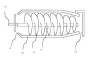
幾種類かの遠心分離装置の型式があるが、図3に示す構造の遠心分離装置が本発明に最も適したものである。当該遠心分離装置は、スラリー供給管8、スラリー供給口9、高速回転する円筒型の外筒10、および、外筒10の内部面に沈殿してきた粉体を掻き出す排出スクリュー11、分離後の液体排出部12、および、粉体排出口13から構成されている。なお、外筒10は、粉体排出口13方向に狭くなるテーパーを有している。外筒10は、毎分1,200〜4,000回転で高速回転しており、300〜3,000Gの遠心力を発生させている。また、外筒10と排出スクリュー11には回転数に差速がついている。この差速は毎分1〜30回転程度である。
上記に説明した遠心分離装置の型式のうち、図3に示される遠心分離装置において、外筒10の回転軸がほぼ鉛直方向、つまり、重力が作用する方向、を向いているものを用いると、本発明の効果が大きくなる。回転軸がほぼ鉛直方向を向いていると、スラリー供給口9からのスラリーの供給が外筒10の円周に対してほぼ均一になる。この結果、スラリーが外筒10に当たった時の粒子の分散状態が変化することを最小限に押さえられる効果がある。更に、粒子の含有水分が低くなると、縦型の遠心分離装置5の場合は、粉体排出口13からの粒子の排出が容易となる効果もある。また、この遠心分離装置では、装置が重力によってたわむ問題がないため、機械部品の設置時の寸法精度が高いことから、固液分離性能の良い装置を製作できる効果もある。なお、回転軸の向きは、重力の作用する方向との角度の差が25度程度以内であると良い。
【0032】
油付着粒子を含むスラリーは、スラリー供給管8を経由して、スラリー供給口9から、外筒10に放出される。外筒10には、遠心力がかかっていることから、スラリーは外筒10の内面に押し付けられる。一般に、本発明の方法で処理する粒子の真比重が3〜8kg/リットルと大きいため、粒子は遠心力の作用により、外筒10の内面方向に沈殿する。また、水と油は、比重が1kg/リットル前後と軽いため、外筒10の内面から離れた回転中心の方向に向かい、水・油から粒子が分離する。また、油の比重は0.9kg/リットル前後と水よりも軽いため、水層よりも外筒10から遠い位置に浮く。この水と油の混合物は、排出スクリュー11の間を図3の左方向、つまり、液体排出部12の方向に流れていく。一方、外筒10の内面に沈殿している微粒スケールは、排出スクリュー11で、図3の右方向に掻き出される。この結果、粒子は、外筒10のテーパー部で液体と分離される。その後に、粒子は粉体排出口13から排出される。
【0033】
遠心分離装置5の内部で粒子の滞在時間で10〜300秒間、液体と粒子の分離操作を受けて、粒子に付着していた油が除去される。粒子の滞在時間は、排出スクリュー11の外筒10との差速で調整する。一般に、差速が毎分1回転の場合は、約300秒の粒子滞在時間、また、差速が毎分30回転の場合は、約10秒の粒子滞在時間となる。この差速の範囲であれば、遠心力・時間積が10,000G・秒以上となる。
この処理を終えた粒子の脱油率は70〜90%であり、また、処理後の粒子が含む水分は4〜18質量%となる。一方、従来技術での湿式脱油処理で、同程度の脱油率の処理を行った場合は、処理後の粒子は20〜50質量%の水分を含むことから、本発明の方法で得られた粒子の水分は低い長所がある。したがって、本発明で得られた粒子は、この後の乾燥処理なしで、リサイクル利用が可能となる。
遠心分離装置5から分離された水と油の混合物は水油分離装置6に移されて、ここで、水から油を分離する。分離された水はアルカリ分や添加剤などの有効成分を含んでいるために、この一部をスラリー撹拌槽1に戻すこともある。また、水油分離装置6で分離された油は再利用するか、廃油として処理される。
【0034】
【実施例】
本発明の装置と方法を用いて、油スケール、チタンの削り粉、および、鋼材の削り粉の、3種類の粉体に油が付着しているものを処理した。この結果を表1に示し、また、本発明の条件を外れた処理の結果も比較例として、表1に示す。なお、これらの粒子を処理する装置の全体構成は図2、また、遠心分離装置の型式は図3に示すものである。
圧延油を6.4質量%含んでいる微粒スケールを脱水・脱油した処理操業の結果を実施例1〜3として示す。微粒スケールの平均粒径は、19ミクロンで、また、含有水分は57質量%であった。
【0035】
【表1】
【0036】
この処理後、微粒スケールの油含有率は1.6質量%であり、脱油率は75%であった。また、微粒スケールの水含有率は12質量%であった。このように、本発明の方法を用いることにより、 pH調整をしていないスラリーを処理する場合であっても、良好な脱油率と脱水率を達成できた。
実施例2の操業では、pH調整をしていない水と微粒スケールから構成されるスラリーを遠心力・時間積が10,000G・秒以上の条件で、処理する操業の例である。粒子の条件、スラリーの水比率、スラリーの攪拌条件は実施例1と同じであった。一方、遠心分離装置5の内部で、スラリーに作用する遠心力は1,000Gであり、遠心分離装置5の内部での粒子の平均滞在時間は24秒であったことから、遠心力・時間積は24,000G・秒であった。
【0037】
この処理後、微粒スケールの油含有率は1.1質量%であり、脱油率は83%であり、また、微粒スケールの水含有率は8質量%であった。この結果は、実施例1よりも良好であった。このように、本発明の方法で、遠心力と粒子の滞在時間を適正にすれば、 pH調整をしていないスラリーを処理する場合であっても、高い脱油率と脱水率を達成できた。
次に、実施例3として、ソーダ灰とメタ珪酸ソーダの混合物を用いて、油含有の微粒スケールを含むスラリーのpHを10.6に調整した操業例を示す。微粒スケールの条件は実施例1および2と同一である。スラリー攪拌槽1では、粒子の真容積に対する水の比率が450%であり、また、攪拌動力はスラリー1立方メートル当たり0.55キロワットであった。遠心分離装置5での処理条件は、遠心力が1,000Gであり、遠心分離装置5の内部での微粒スケールの平均滞在時間は22秒であった。したがって、遠心力・時間積は22,000G・秒であった。
【0038】
この結果、処理後の微粒スケールの油含有分は0.78質量%になっていて、脱油率は88%であった。また、含有水分は9質量%まで低下していた。このように、本発明の方法で、スラリーの水のpHを高くすることにより、更に良好な脱油率を達成できた。
次に、実施例3に示される油含有微粒スケールのスラリーの水に対して0.7質量%の比率で、ノニル・エチレン・オキサイドを添加したものを処理した結果を、実施例4として示す。水のpH、スラリー攪拌槽1に内部の攪拌条件、および、遠心分離装置5の処理条件は実施例1と同一であった。この結果、処理後の微粒スケールの油含有分は0.37質量%に、また、含有水分は8%まで低下していた。
【0039】
実施例1から4の処理で得られた微粒スケールを製鉄所内の鉄鉱石焼結工程で粉状の鉄鉱石に混合して使用したが、いずれも操業上の問題もなく、高炉原料用の焼結鉱として利用できた。
従来技術での粒子からの脱油処理で、微粒スケールから油を除去する処理の結果を比較例として示す。方式は、界面活性剤を用いた湿式処理である。微粒スケールは、実施例1から4で用いたものを同じである。
【0040】
この処理では、混合容器の中で、粒子真容積の1400容積%の水を混合して、スラリーを作った。粉のスラリーに、ソーダ灰とメタ珪酸ソーダの混合物を添加して、pHを11.6に調整した。更に、ノニル・エチレン・オキサイドを水に添加した。添加率は、水に対して、0.67質量%であった。このように、スラリーのpHを高く調整して、かつ、界面活性剤を添加した後に、このスラリーを攪拌した。攪拌後、このスラリーを別の容器に移し、ここでスラリーを静置して、油を浮上させた。浮上時間は、約12分であった。その後、この容器の底にたまった粒子の多い部分を抜きだして、沈殿用のシックナーで濃縮して、その後に、ピット内で沈殿脱水処理をした。
この処理後の微粒スケールの油含有率は0.9質量%であり、含水率は37質量%であった。つまり、比較例でも、技術的には実施例3とほぼ同等の脱油率までできた。ただし、脱水が不十分であったため、この処理の後に、乾燥処理が必要であった。また、脱油率は本発明の実施例と同様に高いが、この処理の用いたアルカリ源と界面活性剤の量は、実施例4の量の約3倍であり、処理費用は、実施例3の処理費用5倍、また、実施例4の2.5倍であった。このように、従来技術による粒子の油除去は、技術的には可能であるが、費用が多くかかる問題があったが、本発明の方法によれば、従来技術での処理費用の20〜40%のランニングコストで処理できた。
【0041】
実施例5に、粒子径が小さい微粒スケールを処理した例を示す。この微粒スケールの粒子径は6.8マイクロメートルであり、油含有率は9.7質量%であった。水との混合や攪拌などの条件は、実施例1とほぼ同一である。ただし、粒子系が小さいことから、300〜1500G程度の遠心力では、脱油と脱水が十分ではなかった。したがって、遠心力を2500Gとして、かつ、粒子の遠心分離装置内の滞在時間を18秒とした。この条件での遠心力・時間積は45,000G・秒であった。この処理により、微粒スケールの油含有率は1.3質量%となり、脱油率は87%であった。このような特に微粒子のスケールの場合は、遠心分離装置を用いた一般的な脱水・脱油処理での脱油率は50〜70%程度である。また、含水率も11質量%まで下がっていた。したがって、従来技術を大幅に上回る脱油率を達成できた。
油が付着しているチタンの削り粉を処理した結果を実施例6として示す。粒子の平均系は7マイクロメートルであり、潤滑油が8.8質量%付着していた。スラリー攪拌槽1の内部で、この粒子の真容積に対して、600容積%の水が混じったスラリーを作った。スラリーの攪拌条件は、スラリー1立方メートル当たり0.55キロワットの攪拌動力であった。なお、スラリーの水には、アルカリ源や界面活性剤は添加しなかった。遠心分離装置5での処理条件は、遠心力が2,000Gであり、遠心分離装置5の内部での微粒スケールの平均滞在時間は12秒であった。したがって、遠心力・時間積は24,000G・秒であった。
【0042】
この結果、処理後の微粒チタン削り粉の油含有分は1.1質量%になっていて、脱油率は88%であった。また、含有水分は7質量%まで低下していた。その後の簡単な処理で、チタン原料として使用できた。
鋼材の削り粉を処理した結果を実施例7として示す。粒子の平均系は150マイクロメートルであり、水溶性油が7.9質量%付着していた。スラリー攪拌槽1の内部で、この粒子の真容積に対して、680容積%の水が混じったスラリーを作った。スラリーの攪拌条件は、スラリー1立方メートル当たり0.92キロワットの攪拌動力であった。なお、スラリーの水には、アルカリ源や界面活性剤は添加しなかった。遠心分離装置5での処理条件は、遠心力が2,000Gであり遠心分離装置5の内部での微粒スケールの平均滞在時間は19秒であった。したがって、遠心力・時間積は38,000G・秒であった。
この結果、処理後の鋼材削り粉の油含有分は0.8質量%になっていて、脱油率は90%であった。また、含有水分は4質量%まで低下していた。回収された削り粉は、そのままの状態で、製鉄原料として、電気炉で利用された。
【0043】
【発明の効果】
本発明の方法および装置を用いることにより、油が付着している金属または金属化合物の粒子から、燃焼を行わずに、油を除去することができる。本発明の方法では、従来の脱油処理よりも、簡単な設備構成で、ランニングコストも安い、経済的な処理が行えるなど、産業上有用な著しい効果を奏する。
【図面の簡単な説明】
【図1】本発明者らが行った、遠心分離装置の遠心力と微粒スケールの機内滞在時間の積と微粒スケールの脱油率の関係を示す図である。
【図2】本発明を行う油を含む微粒スケールから油を除去する装置の全体構成を示す図である。
【図3】本発明で用いる遠心分離装置の1例を示す図である。
【符号の説明】
1 :油スケール混合槽、
2 :添加剤供給装置、
3 :スラリー輸送ポンプ、
4 :スラリー配管、
5 :遠心分離装置、
6 :水油分離装置、
7 :水添加装置、
8 :スラリー供給管、
9 :スラリー供給口、
10 :外筒、
11 :排出スクリュー、
12 :液体排出部、
13 :粉体排出口、[0001]
BACKGROUND OF THE INVENTION
The present invention relates to the removal of powders such as metal scales containing oil and water generated in rolling processes in the steel industry and metalworking industry, and metal powders to which oil generated in metal grinding or polishing processes has adhered. It relates to oil and dehydration.
[0002]
[Prior art]
In the steel industry and metalworking industry, swarf and grinding powder generated during processing of metal materials such as iron, aluminum and copper, scales generated during heating and hot rolling of steel, and abrasives for metal surface processing A large amount of powder is generated. Some of these powders are mixed with oil used for surface lubrication during processing and mechanical lubrication during rolling.
[0003]
These oil-adhered powders have various generation causes, but generally have a particle diameter of 2 micrometers to several millimeters, and a lubricating oil or the like is attached to the surface. Although there are various ratios of oil adhering to these particles, it is generally 1 to 10% by mass.
Examples of the particles to which oil adheres include abrasive powder and grinding powder generated during processing of a metal material. For example, in a metal cutting process, for lubrication, a metal material is ground with a bit or the like while applying a mineral oil or the like, so that a large amount of oil adheres to the powder. The polishing powder and the grinding powder have a particle diameter of 0.1 to several millimeters, and the adhered oil ratio is about 1 to 10% by mass. The types of oil include water-soluble oils and water-insoluble mineral oils.
[0004]
Since this oil becomes an obstacle when abrasive powder and grinding powder (hereinafter, these powders are referred to as shaving powder) are recycled as metal raw materials, wet deoiling treatment is mainly performed. First, water is added to the shavings to which oil has adhered to make a mixed slurry. A surfactant is added to the mixed slurry, and this is stirred to mix the oil adhering to the shavings into water. After draining the slurry in this state, the adhered oil is removed by washing again with water. After removing the oil from the shavings by this treatment, the oil is recycled in a metal melting and refining furnace such as an electric furnace or converter. Moreover, the scale which generate | occur | produces at the time of heat rolling generate | occur | produces in the process which processes a hot steel piece and a metal piece mechanically. In this process, a scale formed by oxidizing the surface of iron or other metal is generated. For example, in the hot rolling process of steel materials, a steel plate is heated to 1100 to 1200 ° C. in a heating furnace, and this is rolled and formed with a metal roll to produce a thin steel plate or a shaped steel. Yes. At this time, a relatively large amount of scale is generated from the surface of the steel slab. The scale amount at this time is 20 to 50 kg per ton of steel. The scale is removed from the billet, usually by jetting high pressure water. This operation is called descaling. The scale removed by descaling is collected in a pit with water and settles here.
[0005]
On the other hand, in the metal rolling process, lubricating oil is used in order to make the rotation and sliding of the machine smooth. A small amount of this lubricating oil leaks from the joint part of the machine parts. This leaked lubricating oil is also collected in the pit along with the drainage of water used for descaling.
As a result, both lubricating oil and scale flow into the pit. In the pit, first, a coarse scale having a size of about 0.2 to several mm is first precipitated in the upstream portion of the pit. Since this portion is a portion where there is little stagnation of the lubricating oil, the scale oil content is low and is 0.4 mass% or less. On the other hand, the fine particle scale of about 0.2 mm or less (average particle diameter is 2 to 75 microns) is precipitated in the downstream portion in the pit. Lubricating oil also accumulates with the fine particle scale in the downstream part of the pit. As a result, 4 to 10% by mass of lubricating oil is mixed in the fine particle scale. Moreover, since this scale is a fine particle, it has the property of easily containing a lot of water. As a result, when recovered from the pit, the moisture ratio is 40 to 55 mass%. This large amount of moisture also becomes a recycling problem with oil.
[0006]
Of the scales, the coarse scale has low oil and water content, so there are few problems with recycling, and it is recycled as raw materials for blast furnaces or directly as raw materials for electric furnaces through ore sintering equipment. ing. On the other hand, it is difficult to recycle a granular scale mixed with lubricating oil (hereinafter referred to as an oil scale) as it is in a sintering apparatus or an electric furnace. This is because the mixed oil evaporates and burns in these devices, making it difficult to treat the exhaust gas.
Then, operation which makes this recyclable by removing the oil adhering from an oil scale is performed. As this method, there are two methods, a heat combustion method and a wet method. First, in the heat combustion type, oil is burned by heating the oil scale with a rotary kiln or the like. The sludge-like oil scale containing water and oil is put into an internal combustion rotary kiln and heated to 500 to 900 ° C. to burn and remove the oil adhering to the oil scale. In addition, in the conventional wet processing, for example, as shown in the sludge processing method of JP-A-51-91817, a method of performing wet oil separation using an aqueous solution to which a chemical agent such as a surfactant is added. There is. First, an oil scale is stirred with water in which a surfactant or the like is mixed in a mixing tank, and the mixed oil is separated.
[0007]
[Problems to be solved by the invention]
As for the deoiling treatment of the shaving powder, in the prior art, wet deoiling treatment is mainly performed. First, a large amount of water is mixed with the shaving powder to which oil has adhered, and a surfactant is added to this mixed slurry, and this is stirred to mix the oil adhering to the shaving powder with water. It was. By this operation, the oil adhering to the shaving powder is dissolved in water, and then the water in which the oil is dissolved is poured, separated, and further washed with water to remove most of the oil adhering to the shaving powder. Had been removed.
[0008]
In this method, 10 to 20 times as much water as the true volume of the particles is required to wash away the oil with a large amount of water and remove the oil. For this reason, a large amount of contaminated water containing oil must be treated. Therefore, the treatment of this method has a problem that a large amount of treatment cost is required due to the treatment of this large amount of oil-contaminated water after removing the oil from the particles. In addition, since the amount of water used for particle cleaning is large, a large amount of surfactant is required to disperse the oil, resulting in a high cost. Therefore, the conventional method for removing oil from shavings has not been an economical deoiling method.
Next, the oil scale treatment also has various problems in the prior art. First, in the method of firing the oil scale, the oil residual ratio of the scale can be reliably reduced to 0.1% by mass or less. However, since the oil is burned in the furnace, the dirty exhaust gas treatment apparatus becomes complicated, and there is a problem that the exhaust gas treatment cost and the construction cost of the apparatus are high. In particular, since the oil scale contains a mixing ratio of about 50% by mass and a large amount of moisture, there is a problem that energy consumption for heat quantity of moisture evaporation is large and the energy cost for this is large.
[0009]
On the other hand, in a wet oil part separation method, for example, an oil-containing sludge treatment method described in JP-A-53-23830, an apparatus for mixing an oil scale and an aqueous solution containing a chemical agent such as a surfactant, oil separation It is the structure which connected apparatus groups, such as an apparatus and the separation tank of the scale from water. However, although the construction cost of the processing apparatus by this method is low compared with the combustion method, it still requires a complicated apparatus and the construction cost is high. Moreover, 10-20 times as large as the true volume of a scale and a large amount of water are required for separation | attachment of adhesion oil similarly to the case of deoiling of a shaving powder. As a result, since a large amount of surfactant is required, the cost of the surfactant is high, and the processing cost is high. Furthermore, although it was necessary to dehydrate the scale after removing the oil, the treatment conditions of the dehydrator were not sufficiently studied, and there was a problem that the fine scale moisture after dehydration was high.
[0010]
Thus, although the wet oil separation method is excellent in principle, the apparatus of the prior art has a complicated configuration and has a problem of high running cost. As a result, although various methods have been proposed, until now, it has hardly been used for actual deoiling treatment of oil scales. In particular, since treatment conditions have not been established in the prior art, fine dehydration of fine particles of about 10 micrometers or less has not been sufficiently deoiled / dehydrated using a centrifugal separator.
Therefore, there has been a demand for a new method that improves the drawbacks of these prior arts and that takes advantage of the advantages of the wet oil separation method. That is, there has been a demand for a new technique with a relatively simple apparatus configuration and a low processing cost for deoiling the particles to which oil has adhered.
[0011]
[Means for Solving the Problems]
The present invention starts from (1)(11).
(1) Mixing powder particles of metal or metal compound to which oil is adhered and water at a volume ratio of 350% or more with respect to the true volume of the powder particles to form a fluid slurry, After stirring the slurry,The product of the acceleration acting on the slurry inside the centrifuge and the residence time of the powder particles inside the centrifuge10,000GA method for treating oil-adhered particles, characterized in that it is at least 2 seconds.
(2) It is characterized by processing a scale having an average particle diameter of 75 micrometers or less, to which oil generated in the rolling process of the steel material is attached (1The processing method of oil adhesion particle | grains as described in).
[0012]
(3) It is characterized by processing metal powder to which oil generated in the process of grinding or polishing metal is attached (1The processing method of oil adhesion particle | grains as described in).
(4) After an average particle size of 12 micrometers or less is mixed with metal or metal compound powder particles to which oil is adhered and water to form a fluid slurry, the slurry is stirred In the centrifugal separator, the slurry is processed by applying a centrifugal force of 1500 times or more of gravitational acceleration (1The processing method of oil adhesion particle | grains as described in).
[0013]
(5) The product of the acceleration acting on the slurry inside the centrifuge and the residence time of the powder particles inside the centrifuge is 20,000 G · sec or more (4The processing method of oil adhesion particle | grains as described in).
(6) The stirring power per 1 cubic meter of slurry, which is a mixture of metal or metal compound powder to which oil adheres and water, is 0.4 kilowatt or more inside the slurry stirring tank. (Any one of 1) to (5)The processing method of oil adhesion particle | grains as described in any one of.
[0014]
(7) A slurry obtained by mixing water having a pH of 9 or more to a metal or metal compound powder to which oil is adhered is stirred and then processed by a centrifugal separator (Any one of 1) to (6)The processing method of oil adhesion particle | grains as described in any one of.
(8) A surfactant is added to water having a pH of 9 or more (7The processing method of oil adhesion particle | grains as described in).
[0015]
(9) It has a cylindrical outer cylinder that rotates around the rotation axis and has a taper that narrows in one end direction, and a screw type conveyor device installed inside the cylindrical outer cylinder, and The slurry supply port for supplying the slurry to the cylindrical outer cylinder is present in the rotating shaft portion, and the discharge screw type conveyor device has a differential speed with respect to the rotational speed of the cylindrical outer cylinder. And using a centrifuge having a function of feeding the powder precipitated on the inner surface of the cylindrical outer cylinder in a direction in which the taper is narrowed while rotating (Any one of 1) to (8)The processing method of oil adhesion particle | grains as described in any one of.
(10) It is characterized by using a centrifugal separator whose rotation axis is oriented in the same direction as the direction of gravity action (9The processing method of oil adhesion particle | grains as described in).
(11) The temperature of the slurry in which the oil-adhered particles and water are mixed is set to a state of 50 ° C. or higher and is processed by a centrifugal separator (1) to any one of claims (10)The processing method of oil adhesion particle | grains as described in any one of.
[0019]
DETAILED DESCRIPTION OF THE INVENTION
The inventors of the present invention have studied a method of deoiling metal or metal compound particles (hereinafter simply referred to as particles) to which oil mixed with water adheres. As a result of this research, it was found that if processing conditions were properly adjusted, dehydration was possible at the same time as dehydration with a centrifugal separator. With this method, even with wet processing, a simple process configuration and low cost were achieved. And found that oil removal of the particles was possible.
The inventors have invented a new method in which a slurry of oil-adhered particles and water is stirred under appropriate conditions, and the slurry is separated from water and oil by a centrifugal separator of a type that does not use a filter cloth. In addition, the experiments by the present inventors are that a fine particle scale during rolling of a steel material having an average particle diameter of 2 to 75 micrometers, titanium grinding powder having an average particle diameter of 1 to 50 micrometers, and an average particle diameter of 0.1 to 0.1 μm. 2mm cemented carbide grinding powder, abrasive powder with an average particle size of 10-100 micrometers, oil attached, and iron powder and minerals with an average particle diameter of 5-25 micrometers This was done with a mixture of oils. The present invention has also been confirmed to work effectively with all of these particles.
[0020]
First, in order to efficiently remove oil and water from the particles, it is important that the conditions for stirring the slurry containing the oil-adhered particles and the conditions for dehydration are appropriate. I clarified that. Among the conditions for stirring the slurry containing the oil-attached particles, the ratio of particles to water and the strength of the centrifugal force are the most important. Also, the stirring strength of the slurry, the pH of the water and the surfactant Existence is an important requirement.
First, before the deoiling treatment, it is necessary to improve the stirring state of the slurry of oil-adhering particles and disperse the particles. If the particles are agglomerated in the slurry, the deoiling efficiency is lowered during the subsequent processing in the centrifugal separator. Therefore, a slurry in which particles are well dispersed is produced. In order to disperse particles, it is necessary to increase the water ratio. The present inventors have clarified that when the volume of water is 350% or more of the true volume of the particles, the particles to which oil is attached can be dispersed by making the stirring operation appropriate. Accordingly, the treatment condition of the present invention is that the ratio of the volume of water to the true volume of the particles to which oil is attached is 350% or more, and the slurry is mechanically stirred to disperse the particles inside the slurry. Further, at a water ratio of 500% by volume or more, the particles are well dispersed even under slightly poor stirring conditions. Therefore, it is better if the water ratio to the particles is 500% by volume or more. In the conventional wet deoiling treatment, the volume ratio of water to the true volume of particles is 1000 to 2000%, and therefore the ratio of water contained in the slurry is greatly reduced in the method of the present invention. The true volume of particles is defined by the sum of the volumes of single particles.
[0021]
In order to disperse the particles in the slurry, it is also important to adjust the conditions for mechanical stirring of the slurry. The larger the stirring power of the slurry, the better the dispersion of the particles. The inventors of the present invention have found that when the volume ratio of water to particles is 350% or more, the dispersion state of particles is improved when the slurry stirring power is 0.4 kilowatts or more per cubic meter of slurry.
The slurry in which the particles produced by the above method are dispersed is dehydrated at the same time as dehydrating inside the centrifugal separator. Inside the centrifugal separator, centrifugal force is applied to the entire slurry, and particles having a specific gravity heavier than water are pressed away from the rotation axis. In this process, oil having a specific gravity smaller than that of water moves in a direction closer to the rotation axis. In the centrifugal separator, after this operation, the solid-liquid is separated, so that it is divided into a mixed liquid of water and oil and particles.
[0022]
The present inventors investigated the degree of influence of the centrifugal force acting on the slurry on the deoiling rate of the particles in the centrifugal separator. The example of the experimental result which the present inventors conducted is shown. In the experiment using the centrifugal separator shown in FIG. 3, the centrifugal force is reduced to the gravitational acceleration (9.8 m / s2 = 1G) was changed from 200 times (200G) to 4,000 times (4,000G), and the ratio of the oil content contained in the fine scale recovered from the centrifuge was investigated. The outline of the apparatus in FIG. 3 will be described later. In an experiment in which a fine scale containing 6.4% oil was dehydrated and deoiled, in the case of 200G, the deoiling rate was only 55%. In addition, with this centrifugal force, the oil removal rate hardly changed even in an experiment in which the residence time of the fine particle scale in the centrifugal separator was extended. On the other hand, in the case of 300G centrifugal force, when the residence time in the centrifugal separator of fine particle scale is as short as 20 to 30 seconds, the deoiling rate is as low as 50 to 60%, but the residence time is 100 seconds. Then, the deoiling rate was as good as 80%. When the centrifugal force was 800 G or more, the oil removal rate was as good as 70 to 90% even when the residence time in the fine-scale centrifugal separator was several tens of seconds. This phenomenon occurred because the buoyancy of the oil could not overcome the affinity between the oil and the fine particle scale, and the deoiling did not progress even for a relatively long time, but the strong centrifugal force of 300 G or more In this case, it is because a sufficient force acts on the slurry and deoiling from the particles is possible if an appropriate time is taken.
[0023]
Thus, since the residence time of the particles in the slurry in the centrifugal separator also affects the oil removal rate from the particles, the inventors next removed the residence time of the particles in the slurry in the centrifugal separator. The effect on oil rate was investigated. Inside the centrifugal separator, there are a part for sedimenting particles in the liquid by centrifugal force and concentrating the part, and a part for separating the deposited particles and the liquid. Considering the mechanism of the centrifugal separator, in the case of the method of the present invention, the oil is peeled off from the particles by a strong centrifugal force in the process of sedimentation of the particles in the mixture of oil and water. That is, in the part holding the slurry of the centrifugal separator, the oil layer, the water layer, and the particle concentration layer are arranged in order from the rotation axis. The particle sedimentation speed in the liquid at this time is influenced by the force (proportional to the centrifugal force) acting on the particles and oil and the time. In the solid-liquid separation process, the pressure applied to the liquid between the particles is a factor that determines the speed at which water and oil flow between the particles, and the pressure is proportional to the centrifugal force. In the solid-liquid separation process, the degree of liquid separation is proportional to the elapsed time. Accordingly, the inventors of the present invention have an important influence that the product of the centrifugal force and the residence time of the particles inside the centrifugal separator (hereinafter referred to as centrifugal force / time product) affects the oil removal rate from the fine particle scale. Clarified that it is a physical parameter.
[0024]
Therefore, the present inventors use a centrifugal dehydrator to remove oil from a fine scale while changing centrifugal force and time product in the range of 300 to 3,000 G, which is a range of centrifugal force effective for deoiling. An experiment was conducted to investigate the oil removal rate. The result is shown in FIG. As shown in FIG. 1, when the centrifugal force / time product exceeds 8,000 G · sec, the oil removal rate becomes good. Further, at 10,000 G · sec or more, the oil removal rate is 80 to 85% or more. I was able to achieve it. It was also found that when the centrifugal force / time product was 15,000 G · sec or more, the effect was further improved, and the effect was almost saturated from 20,000 to 30,000 G · sec. Therefore, it is desirable that the centrifugal force / time product is 10,000 G · second or more as a part of the conditions of the present invention. The effect of centrifugal force and time product on deoiling conditions was confirmed by experiments even in the deoiling treatment of shaving powder and abrasive particles to which oil has adhered, but the centrifugal force and time product are still 10,000 G · sec. If it was above, the deoiling rate was favorable.
[0025]
In addition, when the centrifugal force / time product is 10,000 G · second or more, the water content of the particles discharged from the centrifugal separator is reduced, and there is an advantage that the processing in the next step is easy. For example, in the case of deoiling / dehydration treatment with a fine particle scale with an oil-containing average particle size of 19 micrometers, fine-scale water content is obtained under a centrifugal force of 1,000 G and a centrifugal force / time product of 11,000 G · second. Has a moisture content as low as 11% by mass, and it has been confirmed that the briquette molding apparatus can be molded without subsequent drying.
However, the present inventors have found that a strong centrifugal force is required when dehydrating and deoiling particles having a particle size smaller than 12 micrometers. When the particle size is small, the specific surface area is large, oil is easily attached to the particle surface, and water is easily stored between the particles. Therefore, deoiling and dehydration are insufficient under the condition of weak centrifugal force in the present invention. I also found it. When dehydration and deoiling are performed from such fine particles, a centrifugal force of 1500 G or more, desirably 2000 G or more is required. In addition, the centrifugal force / time product is 20,000 G · second or more, which is a favorable treatment condition.
[0026]
Next, the present inventors investigated the influence of the physical properties of water in which particles are dispersed on the deoiling efficiency of the particles. The effect of water pH, which is the main factor affecting the affinity between oil and water, was investigated. As a result, the lubricating oil or the like adhering to the scale is more easily separated from the particles in an alkaline aqueous solution because the affinity between oil and water is improved. As a result of searching for conditions where oil can be easily separated from the scale, the inventors of the present invention can easily separate the oil when the pH of water exceeds 8.5, and when the pH is 9 or more, the oil separation is good. The pH is a value indicating the hydrogen ion concentration in water, and is obtained by reversing the sign of the common logarithm of the hydrogen ion concentration.
[0027]
As a measure for further improving the oil separation of the alkaline aqueous solution, it is preferable to add a surfactant to water having a pH of 9 or more. When demineralizing mineral oil from particles, it is effective to add a nonionic organic compound as a surfactant. As the nonionic organic compound, nonyl / ethylene / oxide, nonylphenol / propylene / oxide, or the like is used. The addition ratio of the nonionic organic compound is particularly effective when mixed at a ratio of 0.3% by mass or more with respect to water. In addition, as an effect of the present invention, since the ratio of water to be treated is small, even when a surfactant is used, the amount of the surfactant added is significantly less than that of the conventional wet deoiling method. There is.
It is also effective to increase the temperature of the slurry inside the centrifugal separator. This is because as the temperature increases, the viscosity of the oil decreases and the oil separation from the particles improves. Further, when the slurry temperature is increased, the viscosity of water is also lowered, and there is an effect that water can be easily separated from the particles. The present inventors have confirmed through experiments that this effect appears when the slurry temperature is 50 ° C. or higher. In particular, when it is desired to improve the oil removal rate, the slurry temperature is set to 80 ° C. or higher.
[0028]
The present inventors have also studied a method of performing a deoiling treatment from particles mixed with water-soluble oil using a centrifuge using the method of the present invention. Since water-soluble oil has a good affinity with water, if a slurry in which particles are well dispersed is produced and used as a condition that allows solid-liquid separation to be satisfactorily performed, the oil can be removed without any problems under the conditions of the present invention. That is, deoiling can be achieved by stirring the mixture with an appropriate mixing ratio of water to particles of 350% by volume, and by setting the strength of the centrifugal force in the centrifugal separator to 300 G or more. Further, the centrifugal force / time product may be set to an appropriate value of 10,000 G · sec or more. It is also effective to set the temperature of the slurry to 50 ° C. or higher.
Next, FIG. 2 shows an example of an apparatus for carrying out the method of the present invention, and the apparatus and method for deoiling the oil-adhered particles of the present invention will be described. This apparatus mainly includes a slurry agitation tank 1, an additive supply device 2, a slurry transport pump 3, a
[0029]
First, the slurry of the metal or metal compound particle | grains and water adhering in the ratio of 1-10 mass% in the slurry stirring tank 1 is formed. In this slurry, the ratio of water to the true volume of particles is 350% or more. Further, when efficient stirring cannot be performed, it is further desirable that the water ratio is 500% by volume or more.
The slurry is sufficiently stirred in the slurry stirring tank 1. The slurry stirring method at this time includes a method such as stirring by an impeller, stirring by jet water, and blowing air from the bottom of the slurry stirring tank 1, and any method may be used. However, in order to carry out good stirring, the stirring power of the slurry is 0.4 kilowatt or more per cubic meter of slurry.
If necessary, an alkali source is added to the slurry using the additive supply device 2. Any alkali source may be used, but it is economical to use an aqueous solution of soda ash, sodium silicate, sodium phosphate, sodium metasilicate, or slaked lime. When the pH of the slurry water in the slurry agitation tank 1 is set to 9 or more by adding an alkali source, the effect of deoiling is increased. Moreover, the additive supply apparatus 2 is used also when adding surfactant.
[0030]
The slurry well stirred in the slurry agitation tank 1 is transported to the
In the
[0031]
Although there are several types of centrifuges, the centrifuge having the structure shown in FIG. 3 is most suitable for the present invention. The centrifugal separator includes a
Among the centrifugal separator types described above, in the centrifugal separator shown in FIG. 3, when the rotation axis of the
[0032]
The slurry containing oil adhering particles is discharged from the
[0033]
In the interior of the
The oil removal rate of the particles after the treatment is 70 to 90%, and the water content of the treated particles is 4 to 18% by mass. On the other hand, when the same degree of deoiling treatment is performed by the wet deoiling treatment in the prior art, the treated particles contain 20 to 50% by mass of water, and thus are obtained by the method of the present invention. Particles have the advantage of low moisture. Therefore, the particles obtained by the present invention can be recycled without subsequent drying treatment.
The mixture of water and oil separated from the
[0034]
【Example】
Using the apparatus and method of the present invention, oils adhered to three types of powders, oil scale, titanium shavings, and steel shavings, were treated. The results are shown in Table 1, and the results of treatment that deviated from the conditions of the present invention are also shown in Table 1 as comparative examples. The overall configuration of the apparatus for treating these particles is shown in FIG. 2, and the model of the centrifuge is shown in FIG.
The result of the processing operation which spin-dry | dehydrated and deoiled the fine grain scale containing 6.4 mass% of rolling oil is shown as Examples 1-3. The average particle size of the fine particles was 19 microns, and the water content was 57% by mass.
[0035]
[Table 1]
[0036]
After this treatment, the oil content of the fine scale was 1.6% by mass and the deoiling rate was 75%. The water content of the fine scale was 12% by mass. As described above, by using the method of the present invention, it was possible to achieve good deoiling rate and dewatering rate even when the slurry not adjusted for pH was processed.
The operation of Example 2 is an example of an operation in which a slurry composed of water and a fine scale not adjusted for pH is treated under a condition of centrifugal force and time product of 10,000 G · sec or more. The particle conditions, slurry water ratio, and slurry stirring conditions were the same as in Example 1. On the other hand, the centrifugal force acting on the slurry inside the
[0037]
After this treatment, the oil content of the fine scale was 1.1% by mass, the deoiling rate was 83%, and the water content of the fine scale was 8% by mass. This result was better than Example 1. As described above, in the method of the present invention, if the centrifugal force and the residence time of the particles are made appropriate, even when a slurry not adjusted for pH is processed, a high deoiling rate and dehydration rate can be achieved. .
Next, as Example 3, an operation example in which the pH of a slurry containing an oil-containing fine particle scale is adjusted to 10.6 using a mixture of soda ash and sodium metasilicate is shown. The conditions of the fine particle scale are the same as in Examples 1 and 2. In the slurry agitation tank 1, the ratio of water to the true volume of particles was 450%, and the agitation power was 0.55 kW per cubic meter of slurry. The processing conditions in the
[0038]
As a result, the oil content of the fine scale after the treatment was 0.78% by mass, and the oil removal rate was 88%. Further, the water content was reduced to 9% by mass. Thus, in the method of the present invention, a better oil removal rate could be achieved by increasing the pH of the slurry water.
Next, a result obtained by treating the oil-containing fine particle scale slurry added with nonyl ethylene oxide at a ratio of 0.7 mass% with respect to water shown in Example 3 is shown as Example 4. The pH of water, the stirring conditions inside the slurry stirring tank 1, and the processing conditions of the
[0039]
The fine particle scales obtained in the treatments of Examples 1 to 4 were mixed with powdered iron ore in the iron ore sintering process in the ironworks, but none of them had operational problems. It was available as a ore.
The result of the process which removes oil from a fine particle scale by the deoiling process from the particle | grains by a prior art is shown as a comparative example. The system is a wet process using a surfactant. The fine particle scale is the same as that used in Examples 1 to 4.
[0040]
In this process, 1400 volume% of the true particle volume of water was mixed in a mixing vessel to form a slurry. A mixture of soda ash and sodium metasilicate was added to the powder slurry to adjust the pH to 11.6. In addition, nonyl ethylene oxide was added to the water. The addition rate was 0.67 mass% with respect to water. Thus, the slurry was stirred after adjusting the pH of the slurry to be high and adding the surfactant. After stirring, the slurry was transferred to another container where the slurry was allowed to stand and the oil was allowed to float. The ascent time was about 12 minutes. Then, the part with many particles which accumulated on the bottom of this container was extracted, it concentrated with the thickener for precipitation, and the precipitation dehydration process was carried out in the pit after that.
The oil content of the fine scale after this treatment was 0.9% by mass, and the water content was 37% by mass. That is, even in the comparative example, the deoiling rate was technically almost the same as in Example 3. However, since the dehydration was insufficient, a drying process was necessary after this process. Further, the oil removal rate is as high as in the examples of the present invention, but the amount of alkali source and surfactant used in this treatment is about three times the amount of Example 4, and the treatment cost is The processing cost of 3 was 5 times, and 2.5 times that of Example 4. As described above, the oil removal of the particles according to the prior art is technically possible, but there is a problem that the cost is high. % Running cost.
[0041]
Example 5 shows an example in which a fine particle scale having a small particle diameter is processed. The particle size of the fine scale was 6.8 micrometers, and the oil content was 9.7% by mass. Conditions such as mixing with water and stirring are substantially the same as in Example 1. However, since the particle system is small, deoiling and dehydration were not sufficient with a centrifugal force of about 300 to 1500 G. Therefore, the centrifugal force was set to 2500 G, and the residence time of the particles in the centrifugal separator was set to 18 seconds. The centrifugal force / time product under these conditions was 45,000 G · sec. By this treatment, the oil content of the fine particle scale was 1.3% by mass, and the oil removal rate was 87%. In the case of such a fine particle scale, the deoiling rate in a general dehydration / deoiling process using a centrifugal separator is about 50 to 70%. Moreover, the moisture content also fell to 11 mass%. Therefore, it was possible to achieve a deoiling rate significantly exceeding that of the prior art.
The result of treating the titanium shavings to which oil is attached is shown as Example 6. The average system of particles was 7 micrometers, and 8.8% by mass of lubricating oil was adhered. Inside the slurry agitation tank 1, a slurry was prepared in which 600% by volume of water was mixed with respect to the true volume of the particles. The slurry stirring conditions were 0.55 kilowatts of stirring power per cubic meter of slurry. Note that no alkali source or surfactant was added to the slurry water. The processing conditions in the
[0042]
As a result, the oil content of the fine titanium shavings after the treatment was 1.1% by mass, and the oil removal rate was 88%. In addition, the water content was reduced to 7% by mass. After that, it could be used as a titanium raw material by simple treatment.
The result of processing the steel shavings is shown as Example 7. The average system of particles was 150 micrometers, and 7.9% by mass of water-soluble oil was attached. In the slurry agitation tank 1, a slurry was prepared in which 680% by volume of water was mixed with respect to the true volume of the particles. The slurry stirring conditions were 0.92 kilowatts of stirring power per cubic meter of slurry. Note that no alkali source or surfactant was added to the slurry water. The processing conditions in the
As a result, the oil content of the steel scrap after treatment was 0.8% by mass, and the oil removal rate was 90%. Further, the water content was reduced to 4% by mass. The collected shavings were used in an electric furnace as an iron-making raw material as they were.
[0043]
【The invention's effect】
By using the method and apparatus of the present invention, oil can be removed from the metal or metal compound particles to which the oil is adhered without burning. In the method of the present invention, there are significant industrially useful effects such as simpler equipment configuration, lower running cost, and economical processing than conventional deoiling processing.
[Brief description of the drawings]
FIG. 1 is a graph showing the relationship between the product of centrifugal force of a centrifugal separator and the residence time of a fine particle scale in the machine and the deoiling rate of the fine particle scale performed by the present inventors.
FIG. 2 is a diagram showing an overall configuration of an apparatus for removing oil from a fine particle scale containing oil according to the present invention.
FIG. 3 is a diagram showing an example of a centrifuge used in the present invention.
[Explanation of symbols]
1: Oil scale mixing tank,
2: Additive supply device,
3: Slurry transport pump,
4: Slurry piping,
5: Centrifuge,
6: Water-oil separator
7: Water addition device,
8: slurry supply pipe,
9: slurry supply port,
10: outer cylinder,
11: discharge screw,
12: Liquid discharge part,
13: Powder outlet
Claims (11)
Translated fromJapanesePriority Applications (1)
| Application Number | Priority Date | Filing Date | Title |
|---|---|---|---|
| JP2002150175AJP3768919B2 (en) | 2001-05-30 | 2002-05-24 | Method for treating oil-adhered particles |
Applications Claiming Priority (3)
| Application Number | Priority Date | Filing Date | Title |
|---|---|---|---|
| JP2001162702 | 2001-05-30 | ||
| JP2001-162702 | 2001-05-30 | ||
| JP2002150175AJP3768919B2 (en) | 2001-05-30 | 2002-05-24 | Method for treating oil-adhered particles |
Publications (2)
| Publication Number | Publication Date |
|---|---|
| JP2003071205A JP2003071205A (en) | 2003-03-11 |
| JP3768919B2true JP3768919B2 (en) | 2006-04-19 |
Family
ID=26615984
Family Applications (1)
| Application Number | Title | Priority Date | Filing Date |
|---|---|---|---|
| JP2002150175AExpired - Fee RelatedJP3768919B2 (en) | 2001-05-30 | 2002-05-24 | Method for treating oil-adhered particles |
Country Status (1)
| Country | Link |
|---|---|
| JP (1) | JP3768919B2 (en) |
Families Citing this family (9)
| Publication number | Priority date | Publication date | Assignee | Title |
|---|---|---|---|---|
| WO2005038408A2 (en)* | 2003-10-22 | 2005-04-28 | Toyota Motor Co Ltd | Mixed liquid separator |
| JP5335289B2 (en)* | 2008-06-05 | 2013-11-06 | 花王株式会社 | Collection method of inorganic powder |
| CN102285653B (en)* | 2011-06-02 | 2013-04-10 | 江苏大阳光辅股份有限公司 | Method for removing carbon impurities in silicon carbide micropowder |
| JP2014073556A (en)* | 2012-10-04 | 2014-04-24 | Dowa Eco-System Co Ltd | Regeneration method of cerium oxide-based abrasive, and regenerated cerium oxide-based abrasive |
| CN104922940A (en)* | 2015-06-29 | 2015-09-23 | 浙江利民化工有限公司 | Waste oil collection device of compressed air storage tank |
| JP6933093B2 (en)* | 2016-11-08 | 2021-09-08 | 住友金属鉱山株式会社 | Analytical method of oil content in metal compound powder |
| JP7644333B2 (en)* | 2021-02-18 | 2025-03-12 | 日本製鉄株式会社 | Powder recovery method and powder recovery equipment |
| JP7644334B2 (en)* | 2021-02-18 | 2025-03-12 | 日本製鉄株式会社 | Powder recovery method |
| JP2023070455A (en)* | 2021-11-09 | 2023-05-19 | ユニマグテック株式会社 | Chip recovery method and chip recovery unit |
- 2002
- 2002-05-24JPJP2002150175Apatent/JP3768919B2/ennot_activeExpired - Fee Related
Also Published As
| Publication number | Publication date |
|---|---|
| JP2003071205A (en) | 2003-03-11 |
Similar Documents
| Publication | Publication Date | Title |
|---|---|---|
| CN104478122B (en) | A kind of method of Separation of Solid and Liquid of incineration of refuse flyash washing slip | |
| JP3768919B2 (en) | Method for treating oil-adhered particles | |
| US5723042A (en) | Oil sand extraction process | |
| US5047083A (en) | Process for de-oiling mill scale | |
| JP2000084567A (en) | Treatment method for wastewater containing cutting oil | |
| EP1396551A1 (en) | Device and method for treating oil-adhered particles | |
| CN106810028B (en) | Hot rolling oil sludge air floatation cleaning and deoiling system and deoiling method | |
| JPS60156523A (en) | Method of recovering pulverized coal from pipeline coal slurry | |
| CN107162000A (en) | A kind of renovation process of silicon carbide blade material | |
| US3257081A (en) | Recovery of waste grinding materials | |
| US4988391A (en) | Process, plant and/or apparatus for treating oil-contaminated debris or like materials | |
| CN106809899B (en) | A kind of hot-rolled advection pool air flotation degreasing system and degreasing method | |
| JP2001341074A (en) | Regenerative processor for inorganic abrasive waste liquid | |
| KR100975877B1 (en) | Cutting fluid for silicon ingot cutting, its manufacturing apparatus and method | |
| CN206315925U (en) | Mud | |
| CN106809936B (en) | A kind of hot-rolled advection pool air flotation cleaning and degreasing system and degreasing method | |
| CN106809912A (en) | Hot rolling oil sludge air floatation oil removal system and oil removal method | |
| JP2006212569A (en) | Method for concentrating slurry | |
| KR101020151B1 (en) | Waste Slurry Recycling Equipment and Recycling Method | |
| US3164463A (en) | Process for handling iron laden wastes in steel mills | |
| RU2221084C2 (en) | Method of cleaning greasy scale and device for realization of this method | |
| Lin | Hydrocycloning thickening: dewatering and densification of fine particulates | |
| RU2217510C2 (en) | Method of processing metalliferrous waste and device for processing the waste | |
| JP5617182B2 (en) | Method for processing iron-containing slurry | |
| WO1982002543A1 (en) | Method for reclaiming paint overspray |
Legal Events
| Date | Code | Title | Description |
|---|---|---|---|
| A131 | Notification of reasons for refusal | Free format text:JAPANESE INTERMEDIATE CODE: A131 Effective date:20051025 | |
| A521 | Request for written amendment filed | Free format text:JAPANESE INTERMEDIATE CODE: A523 Effective date:20051222 | |
| TRDD | Decision of grant or rejection written | ||
| A01 | Written decision to grant a patent or to grant a registration (utility model) | Free format text:JAPANESE INTERMEDIATE CODE: A01 Effective date:20060124 | |
| A61 | First payment of annual fees (during grant procedure) | Free format text:JAPANESE INTERMEDIATE CODE: A61 Effective date:20060202 | |
| R150 | Certificate of patent or registration of utility model | Free format text:JAPANESE INTERMEDIATE CODE: R150 | |
| FPAY | Renewal fee payment (event date is renewal date of database) | Free format text:PAYMENT UNTIL: 20100210 Year of fee payment:4 | |
| FPAY | Renewal fee payment (event date is renewal date of database) | Free format text:PAYMENT UNTIL: 20100210 Year of fee payment:4 | |
| FPAY | Renewal fee payment (event date is renewal date of database) | Free format text:PAYMENT UNTIL: 20110210 Year of fee payment:5 | |
| FPAY | Renewal fee payment (event date is renewal date of database) | Free format text:PAYMENT UNTIL: 20120210 Year of fee payment:6 | |
| FPAY | Renewal fee payment (event date is renewal date of database) | Free format text:PAYMENT UNTIL: 20130210 Year of fee payment:7 | |
| FPAY | Renewal fee payment (event date is renewal date of database) | Free format text:PAYMENT UNTIL: 20130210 Year of fee payment:7 | |
| S531 | Written request for registration of change of domicile | Free format text:JAPANESE INTERMEDIATE CODE: R313531 | |
| R350 | Written notification of registration of transfer | Free format text:JAPANESE INTERMEDIATE CODE: R350 | |
| FPAY | Renewal fee payment (event date is renewal date of database) | Free format text:PAYMENT UNTIL: 20130210 Year of fee payment:7 | |
| S533 | Written request for registration of change of name | Free format text:JAPANESE INTERMEDIATE CODE: R313533 | |
| FPAY | Renewal fee payment (event date is renewal date of database) | Free format text:PAYMENT UNTIL: 20130210 Year of fee payment:7 | |
| R350 | Written notification of registration of transfer | Free format text:JAPANESE INTERMEDIATE CODE: R350 | |
| FPAY | Renewal fee payment (event date is renewal date of database) | Free format text:PAYMENT UNTIL: 20140210 Year of fee payment:8 | |
| R250 | Receipt of annual fees | Free format text:JAPANESE INTERMEDIATE CODE: R250 | |
| R250 | Receipt of annual fees | Free format text:JAPANESE INTERMEDIATE CODE: R250 | |
| R250 | Receipt of annual fees | Free format text:JAPANESE INTERMEDIATE CODE: R250 | |
| LAPS | Cancellation because of no payment of annual fees |