JP3763645B2 - Optical fiber wiring equipment - Google Patents
Optical fiber wiring equipmentDownload PDFInfo
- Publication number
- JP3763645B2 JP3763645B2JP18259597AJP18259597AJP3763645B2JP 3763645 B2JP3763645 B2JP 3763645B2JP 18259597 AJP18259597 AJP 18259597AJP 18259597 AJP18259597 AJP 18259597AJP 3763645 B2JP3763645 B2JP 3763645B2
- Authority
- JP
- Japan
- Prior art keywords
- optical fiber
- support
- outer guide
- stage
- guide
- Prior art date
- Legal status (The legal status is an assumption and is not a legal conclusion. Google has not performed a legal analysis and makes no representation as to the accuracy of the status listed.)
- Expired - Fee Related
Links
Images


Landscapes
- Light Guides In General And Applications Therefor (AREA)
Description
Translated fromJapanese【0001】
【発明の属する技術分野】
本発明は、光ファイバの余長部を整理して収納すると共に該光ファイバを分配接続する光ファイバ配線装置に関するものである。
【0002】
【従来の技術】
図2は、従来の光ファイバ配線装置の要部を示す斜視図である。
この光ファイバ配線装置では、背面パネル11と該パネル11に固定された2つの支柱12a,12bを有している。支柱12aにより、例えば6本のアウタガイド13a〜13fの一端が支持されている。支柱12bにより、例えば6本のアウタガイド14a〜14fの一端が支持されている。各アウタガイド13a〜13fと各アウタガイド14a〜14fとは、x方向に所定間隔を持って対向し、それらがx方向に垂直なy方向に多段に配列されている。アウタガイド13aとアウタガイド14aとが一段目のアウタガイド対を形成している。同様に各アウタガイド13b〜13fとそれらに対向するアウタガイド14b〜14fとで、2〜6段目のアウタガイド対が形成されている。
各アウタガイド13a〜13fはそれぞれ筒状であり、該各アウタガイド13a〜13fの他端には、摺動自在に棒状の第1のインナガイド15a〜15fがそれぞれ嵌入されている。同様に各アウタガイド14a〜14fも、それぞれ筒状であり、該各アウタガイド14a〜14fの他端には、摺動自在に棒状の第2のインナガイド16a〜16fがそれぞれ嵌入されている。なお、各インナガイド15a〜15f,16a〜16fと各アウタガイド13a〜13f,14a〜14fとの間には、該インナガイド15a〜15f,16a〜16fが抜け落ちないように、適宜の手段が講じられている。
【0003】
簡単化のため図2では1段で示しているが、6段のアウタガイド対に対応して6段の収納トレイ17が用意されている。各収納トレイ17は、各段のアウタガイド対の方向、つまり、x,y方向に垂直なz方向に出し入れ可能にスライドするものである。収納トレイ17は矩形の底面板を有している。収納トレイ17の底面板の第1の側部であるアウタガイド13a〜13f側の側部18には、支柱12a側の側壁19aと、第1の光ファイバFを引込むために解放された引込み口19bとが配設されている。収納トレイ17の底面板の第2の側部であるアウタガイド14a〜14f側の側部20には、支柱12b側の側壁21aと、第2の光ファイバFを引込むために解放された引込み口21bが配設されている。収納トレイ17の底面板の背面パネル11側の側部には背面壁22が形成されている。収納トレイ17の背面パネル11側と対向する側部には、前面壁23が形成されている。背面壁22には背面パネル11に磁気力等で吸着する吸着部材24が取付けられている。この吸着部材24は、収納トレイ17が不本意にスライドすることを防止する機能を有している。前面壁23には、収納トレイ17を人為的に出し入れするための切欠部25a,25bが形成されている。
【0004】
収納トレイ17の底面板上には、光ファイバFの余長部を収納するための収納部26が設けられている。収納部26には、光ファイバFの余長部が許容最小曲率以上の径をもって当接可能なRガイド27と、光ファイバFの余長部を止めるため複数の心線止め治具28と、心線保持具29等が配設されている。また、収納トレイ17の底面板上には、コネクタ接続された光ファイバFの接続部を収容するためのコネクタホルダ30と、融着接続された光ファイバFの接続部を収容するためのスリーブホルダ31とが適宜搭載されている。
前面壁23の両側には、連結片32a,32bが配置されている。連結片32a,32bは、捩子33a,33bで各段のインナガイド対15a,16a、インナガイド対15b,16b、インナガイド対15c,16c、インナガイド対15d,16d、インナガイド対15e,16e、またはインナガイド対15f,16fの先端に係止されて、収納トレイ17をそれらインナガイド対に固定する機能を有している。
側壁19aの外面には、スライダ34が取付けられ、側壁21aの外面には、スライダ35が取付けられている。スライダ34は、各アウタガイド13a〜13fに対して収納トレイ17を摺動自在に支えるものであり、スライダ35は、各アウタガイド14a〜14fに対して収納トレイ17を摺動自在に支えるものである。
【0005】
以上のような構成の光ファイバ配線装置の使用方法を説明する。
光ファイバ配線装置は、光ファイバFの余長を収納トレイ17を用いて整理して収納したり、収納トレイ17上で該光ファイバFを分配して接続するものである。収納トレイ17を引出した状態で、光ファイバFを収納トレイ17に引込む。各引込み口19b,21bから引込まれる光ファイバFは、例えばアウタガイド13a,13bまたはインナガイド15a,15b、或いはアウタガイド14a,14bまたはインナガイド16a,16bに懸架される。
収納トレイ17が引出された状態であっても、スライダ34がアウタガイド13a〜13f上に、及びスライダ35がアウタガイド14a〜14f上に位置するように、該スライダ34,35は、収納トレイ17の支柱12a,12bに近い側に取付けられている。もし、支柱12a,12bから遠い位置に取付けられていると、スライダ34,35がアウタガイド対から外れ、再度収納トレイ17を支柱12a,12b側に押し込んで挿着することが困難になる。この問題を回避するために、アウタガイド13a〜13f,14a〜14fを長めに作成しておくと、収納トレイ17を挿着した状態での、光ファイバ配線装置の外形がz方向に大きくなってしまうという問題がある。
収納トレイ17に引込まれた光ファイバFは、余長部が収納部26内のRガイド27と複数の心線止め治具28とに巻回され、さらに心線保持具29に保持される。このようにして光ファイバFを把持する。ここで、光ファイバF同士を接続する場合、その接続部のコネクタ或いはスリーブが、コネクタホルダ30或いはスリーブホルダ31で保持される。光ファイバFの整理、或いは接続が終了すると、収納トレイ17を光ファイバ配線装置内に押して挿着する。このようにして、光ファイバの配線及び整理を行う。
【0006】
【発明が解決しようとする課題】
しかしながら、従来の光ファイバ配線装置には、次のような課題があった。
多数の光ファイバに対する余長の整理等を行う場合には、複数段の収納トレイ17が利用される。よって、収納トレイ17を挿着した状態では、多数条の光ファイバFが各アウタガイド13a〜13fの間、及び各アウタガイド14a〜14fの間から懸架される。このとき、任意の収納トレイ17をスライドさせて引出したり、押し戻して挿着すると、スライダ34,35に光ファイバFが引っ掛かり、光ファイバFに損傷や断線が発生する。一方、光ファイバ配線装置の外形を小さくするために、スライダ34,35を、収納トレイ17の挿着時に支柱12a,12bに当接するように配置した場合には、スライダ34,35と支柱12a,12bの間に光ファイバFが挟まれて押圧される。光ファイバFは押圧されると伝送特性が劣化する。また、その圧力が強ければ、光ファイバFに損傷や断線が発生する。
【0007】
【課題を解決するための手段】
前記課題を解決するために、本発明のうちの第1の発明は、x方向に所定間隔を持って対向する筒状の第1及び第2のアウタガイドからなるアウタガイド対の一端が該x方向に対して垂直なy方向に複数段所定間隔を持って支持体に支持された複数段のアウタガイド対と、前記各段のアウタガイド対の他端から摺動自在に対を成してそれぞれ嵌入された棒状の第1及び第2のインナガイドからなる複数段のインナガイド対と、前記x方向に所定の間隔を持って対向する第1及び第2の側部を有し、前記各段の第1のアウタガイド及び第1のインナガイドに懸架されて該第1の側部からそれぞれ引込まれた配線用の第1の光ファイバと、前記各段の第2のアウタガイド及び第2のインナガイドに懸架されて該第2の側部からそれぞれ引込まれた配線用の第2の光ファイバとを、余長を持たせて収納する複数段の収納トレイと、前記各段の収納トレイを前記各段のインナガイド対にそれぞれ固定する複数の固定手段と、前記各段の収納トレイにおける第1の側部の支持体側にそれぞれ設けられ、該収納トレイを前記第1のアウタガイドに対して摺動自在に支える複数の第1の摺動手段と、前記各段の収納トレイにおける第2の側部の支持体側にそれぞれ設けられ、該収納トレイを前記第2のアウタガイドに対して摺動自在に支える複数の第2の摺動手段とを、備えた光ファイバ配線装置において、前記各第1及び第の摺動手段を次のように構成している。
【0008】
前記各第1の摺動手段は、舌状をなす支持部をそれぞれ有し、該支持部の根元部が前記各段の収納トレイの第1の側部側に取付けられ、該支持部の先端部が前記x方向に前記第1のアウタガイドの外周面に沿って突出し、該支持部の底面全体が前記第1のアウタガイドの外周面に係合して摺接し、前記各第2の摺動手段は、舌状をなす支持部をそれぞれ有し、該支持部の根元部が前記各段の収納トレイの第2の側部側に取付けられ、該支持部の先端部が前記x方向に前記第2のアウタガイドの外周面に沿って突出し、該支持部の底面全体が前記第2のアウタガイドの外周面に係合して摺接している。
さらに、前記各第1の摺動手段の支持部の外縁には、該支持部の移動による前記第1の光ファイバの当接時に、該第1の光ファイバを前記第1のアウタガイドから離れる方向に浮揚する傾斜角をそれぞれ形成し、前記各第2の摺動手段の支持部の外縁には、該支持部の移動による前記第2の光ファイバの当接時に、該第2の光ファイバを前記第2のアウタガイドから離れる方向に浮揚する傾斜角をそれぞれ形成している。
【0009】
第2の発明は、第1の発明と同様の光ファイバ配線装置において、前記各第1の摺動手段の支持部における前記支持体側の側部には、該支持部の移動による該支持体との当接時に、該支持体との間に前記第1の光ファイバを収容する退避部をそれぞれ形成し、前記各第2の摺動手段の支持部における前記支持体側の側部には、該支持部の移動による該支持体との当接時に、該支持体との間に前記第2の光ファイバを収容する退避部をそれぞれ形成している。
【0010】
第1の発明によれば、以上のように光ファイバ配線装置を構成したので、第1及び第2の摺動手段における支持部の底面全体と第1及び第2のアウタガイドとの間の間隙がなくなり、各段の収納トレイを支える第1及び第2の摺動手段を各段のインナガイド対の摺動と共に摺動させても、第1及び第2の光ファイバの食い込みが発生しない。しかも、各段の収納トレイを支える第1及び第2の摺動手段を各段のインナガイド対の摺動と共に摺動させたとき、第1及び第2の光ファイブが第1及び第2の摺動手段の支持部に当接しても、これらの各支持部の外縁に形成された傾斜部により、該第1及び第2の光ファイバが、第1及び第2のアウタガイドまたは第1及び第2のインナガイドから離れる方向に浮揚され、第1及び第2の光ファイバが、第1及び第2の摺動手段に引っ掛かることが防止される。
【0011】
第2の発明によれば、各段の収納トレイを支える第1及び第2の摺動手段を各段のインナガイド対の摺動と共に摺動させたとき、第1及び第2の光ファイバを引掛けた状態で第1及び第2の摺動手段の支持部が支持体に当接しても、該第1及び第2の光ファイバが、退避部に収容されて押圧されない。従って、前記課題を解決できるのである。
【0012】
【発明の実施の形態】
図1は、本発明の実施形態を示す光ファイバ配線装置の要部を示す斜視図であり、従来の図2中の要素と共通する要素には、共通の符号が付されている。
この光ファイバ配線装置は、複数段の収納トレイ17に取付けられた第1及び第2の摺動手段であるスライダの構造を改良し、該収納トレイ17の引き出しと挿着による光ファイバの損傷等を防止する構成であり、スライダ以外の各部の構造は従来の光ファイバ配線装置と同様である。
この光ファイバ配線装置では、背面パネル11と該パネル11に固定された2つの支柱12a,12bとで全体を支える支持体が構成されている。支柱12aによって、y方向に並んだ第1のアウタガイド13a〜13fの一端が支持されている。支柱12bにより、y方向に並んだ6本の第2のアウタガイド14a〜14fの一端が支持されている。各アウタガイド13a〜〜13fと各アウタガイド14a〜14fは、x方向に一定間隔を持って対向している。
対向するアウタガイド13aとアウタガイド14aとが、一段目のアウタガイド対を形成している。同様に各アウタガイド13b〜13fとそれらに対向するアウタガイド14b〜14fとで、2〜6段目のアウタガイド対が形成されている。各アウタガイド13a〜13fの他端に、摺動自在に棒状の第1のインナガイド15a〜15fがそれぞれ嵌入され、各アウタガイド14a〜14fの他端に、摺動自在に棒状の第2のインナガイド16a〜16fがそれぞれ嵌入されている。各インナガイド15a〜15fと各インナガイド16a〜16fとが、各段のインナガイド対を構成している。各インナガイド15a〜15f,16a〜16fと各アウタガイド13a〜13f,14a〜14fとの間には、該インナガイド15a〜15f,16a〜16fが抜け落ちないように、適宜の手段が講じられている。
【0013】
6段のアウタガイド対に対応して図2と同様の構成の6段の収納トレイ17が用意されている。収納トレイ17の矩形の底面板の第1の側部であるアウタガイド13a〜13f側の側部18に設けられた支柱12a側の側壁19aに、この実施形態の特徴である第1の摺動手段のスライダ40aが取付けられ、第2の側部であるアウタガイド14a〜14f側の側部20に設けられた支柱12b側の側壁21aに、第2の摺動手段のスライダ40bが取付けられている。前面壁23の両側に設けられた固定手段である連結片32a,32bによって、各段のインナガイド対15a,16a、インナガイド対15b,16b、インナガイド対15c,16c、インナガイド対15d,16d、インナガイド対15e,16e、またはインナガイド対15f,16fに、各段の収納トレイ17が固定されている。
図3(a),(b)は、図1中のスライダ40a,40bの形状を示す構造図であり、同図(a)は正面図、同図(b)は側面図を示している。
【0014】
スライダ40a,40bは同様の構造であり、取付け部41と支持部42とが一体になって構成されている。取付け部41は板状であり、各スライダ40a,40bを図1中の側壁19a,21aに捩子で係止するための取付け穴41a,41bが、開孔されている。支持部42は舌状をなし、この舌状の根元部42aが取付け部41に接し、該舌状の先端部がアウタガイド13a〜13fまたは14a〜14fの軸方向(z方向)に垂直なx方向に該アウタガイド13a〜13fまたは14a〜14fの外周面に沿って突出している。支持部42の底部42bの全体には、アウタガイド13a〜13fまたは14a〜14fの外周面に係合して摺接する曲面42cを有している。曲面42cの先端部は、x方向においてアウタガイド13a〜13fまたは14a〜14fの外径直径より短く形成されている。
支持部42の側部42dから頭部42eにかけての支持部42の外縁42fには、円弧状の丸み42gが形成されている。この丸み42gは、テンションフリーの光ファイバFが当接したときに、その接点において当接した光ファイバFに対して接線方向の傾斜角を形成し、該光ファイバFを接線に沿って移動させる機能を有している。即ち、丸み42gは、光ファイバFをアウタガイド13a〜13fまたは14a〜14fから離れる方向に浮揚する機能を有している。さらに、この丸み42gは、支柱12a,12bに支持部42が当接した場合に、光ファイバFを収容する退避部42hを形成することにもなる。
【0015】
図4は、図3の摺動状態を示す図である。
スライダ40a,40bは、支持部42の底部42bがアウタガイド13a〜13fまたは14a〜14eに係合され、該アウタガイド13a〜13fまたは14a〜14eの方向に沿って、つまり、z方向に摺動する。
次に、図1の光ファイバ配線装置の使用方法を説明する。
この光ファイバ配線装置も、光ファイバFの余長を収納トレイ17を用いて整理して収納したり、収納トレイ17上で該光ファイバFを分配して接続するものである。装置の導入或いはメンテナンスに際し、収納トレイ17をスライドさせて引出した状態で、光ファイバFを収納トレイ17に引込む。引込まれた光ファイバFは、各アウタガイド13a〜13bの間、各アウタガイド14a〜14bの間、各インナガイド15a〜15bの間、または各インナガイド15a〜15bの間に懸架される。収納トレイ17に引込まれた光ファイバFは、従来と同様に余長部等が収納されて整理される。整理や接続を終了すると、収納トレイ17を光ファイバ配線装置内に押して挿着する。収納トレイ17が挿着されると、該収納トレイ17は、吸着部材24によって背面パネル11に軽く固定され、以後の不本意なスライドが防止される。
【0016】
図5は、光ファイバの食込みを示す図である。
各段の収納トレイ17を引出したり挿着する場合、アウタガイド13a〜13fまたは14a〜14f上をスライダ40a,40bが、図4のように摺動することになる。従来の光ファイバ配線装置では、図5のようにスライダ34,35の支持部34a,35aがx方向に突出し、この先端部34b,35bがアウタガイド13a〜13fまたは14a〜14fの外周面に沿って下方向(y方向)
に屈曲して、該アウタガイド13a〜13fまたは14a〜14fのz方向の中心軸よりも下方向に延びている。そのため、スライダ34,35の支持部34a,35aの先端部34b,35bと、各アウタガイド13a〜13fまたは14a〜14fの外周面(図5の左下外周面)との間に間隔が生じ、スライダ34,35の摺動時に光ファイバFが該間隔に食い込み、更なるスライダ34,35の摺動で光ファイバFに断線等の損傷を起たすことがあった。
ところが、本実施形態のスライダ40a,40bでは、支持部42の底部全体の曲面42cをアウタガイド13a〜13fまたは14a〜14fの外周面に係合して摺接する構造にしたことで、支持部42の先端部とアウタガイド13a〜13fまたは14a〜14fとの間に間隔を生ずることを防ぐことができることから、光ファイバFを引掛けることがなくなり、さらに、光ファイバFの食い込みも発生しない。
【0017】
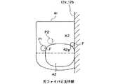
図6は、光ファイバと支持部42の関係を示す図である。
各段の収納トレイ17を引出したり挿着する際、アウタガイド13a〜13fまたは14a〜14f上をスライダ40a,40bが摺動し、既に懸架されている光ファイバFが、移動する支持部42に当接することがある。例えば、図6の位置P1で当接した光ファイバFは、丸み42gの接線方向に浮揚されて位置P2に移動する。つまり、テンションフリーに懸架された光ファイバFは、アウタガイド13a〜13fまたは14a〜14f側から離れる方向に浮揚され、支持部42での引っ掛かりが発生しない。
また、各段の収納トレイ17を挿着する際、スライダ40a,40bの支持部42が支柱12a,12bに当接すると、丸み42gは、支柱12a,12bとの間に間隙K2を作る。この間隙K2は、光ファイバFの退避部42hであり、スライダ40a,40bの摺動で該スライダ40a,40bに押された光ファイバFは退避部42hに収容され、支柱12a,12bとの間で押圧されることはない。
以上のように、本実施形態の光ファイバ配線装置は、従来では得られない次の(1)〜(3)のような利点を有している。
【0018】
(1) スライダ40a,40bにおける支持部42の底部全体の曲面42cを、アウタガイド13a〜13fまたは14a〜14fの外周面に係合して摺接する構造にしたので、支持部42の先端部とアウタガイド13a〜13fまたは14a〜14fとの間に間隔を生じることを防ぐことができることから、光ファイバFを引掛けることがなくなり、さらに、光ファイバFの食込みによる事故も防止できる。よって光ファイバ配線装置のメンテナンス等が合理化できる。
(2) 各スライダ40a,40bの支持部42の外縁42fに、丸み42gを形成したので、当接した光ファイバFが浮揚され、スライダ40a,40bの移動で引掛けて、光ファイバFを損傷したり断線させることがなくなる。
(3) 各スライダ40a,40bの支持部42の外縁42fに、退避部42hを作る丸み42gを形成したので、支持部42が支柱12a,12bに当接する場合でも、光ファイバFが押圧されず、光ファイバFの特性劣化が防止できると共に、光ファイバFの損傷と断線を防止できる。
なお、本発明は、上記実施形態に限定されず種々の変形が可能である。その変形例としては、例えば次のようなものがある。
【0019】
(i) 収納トレイ17に搭載する各治具の種類及び配置は、図1及び図2に限定されず、収納する光ファイバFの種類に応じて変更することが可能である。
(ii) 支持部40の外縁42fに、丸み42gを形成して実質的な傾斜角と退避部42hを作成しているが、丸み42gに限定されず、例えば、外縁42fにテーパーを形成しても同様に、実質的な傾斜角と退避部42hを作成できる。
(iii) 各スライダ40a,40bは取付け部41を有し、該取付け部41で側壁19a,21aに取付けられる構成であるが、支持部42を側壁19a,21aと一体に構成すれば、取付け部41は省略できる。
(iv) 図7は、スライダの変形例を示す側面図である。
各スライダ40a,40bは、それぞれ一つの支持部42を有し、片持ちでアウタガイド13a〜13f,14a〜14bに対して収納トレイ17を支えているが、図7のように、支持部42と同一形状を有する支持部43を対向させて設け、各アウタガイド13a〜13f,14a〜14bを両持ちにする構成でもよい。
【0020】
【発明の効果】
以上詳細に説明したように、第1の発明によれば、各第1、第2の摺動手段における支持部の底面全体を、第1、第2のアウタガイドの外周面に係合して摺接する構造にしたので、第1、第2の光ファイバの食込みが防止されて損傷がなくなる。よって、メンテナンス等の合理化が可能になる。しかも、各第1、第2の摺動手段の支持部の外縁に、第1、第2の光ファイバを浮揚する傾斜角をそれぞれ形成したので、該第1、第2の摺動手段が摺動しても、第1、第2の光ファイブが引掛からなくなり、それらの損傷と断線とが防止され、メンテナンス等の作業効率が改善される。
第2の発明によれば、各第1、第2の摺動手段の支持部における支持体側の側部に、退避部をそれぞれ形成したので、摺動手段の支持部が支持体に当接しても、光ファイバが押圧されず、損傷と断線とが防止され、メンテナンス等の作業効率が改善できる。
【図面の簡単な説明】
【図1】本発明の実施形態を示す光ファイバ配線装置の要部を示す斜視図である。
【図2】従来の光ファイバ配線装置の要部を示す斜視図である。
【図3】図1中のスライダ40a,40bの形状を示す構造図である。
【図4】図3の摺動状態を示す図である。
【図5】 光ファイバの食込みを示す図である。
【図6】光ファイバと支持部42の関係を示す図である。
【図7】スライダの変形例を示す側面図である。
【符号の説明】
12a,12b 支柱(支持体)
13a〜13f,14a〜14f 第1及び第2のアウタガイド
15a〜15f,16a〜16f 第1及び第2のインナガイド
17 収納トレイ
32a,32b 連結片(固定手段)
40a,40b スライダ(第1及び第2の摺動手段)
41 取付け部
42 支持部
42b 支持部の底部
42c 摺接面
42d 支持部の側部
42f 外縁
42g 支持部に形成された丸み(傾斜角)
42h 退避部
F 光ファイバ[0001]
BACKGROUND OF THE INVENTION
The present invention relates toan optical fiber wiring apparatus for distributing connecting theoptical fiber as well as accommodating to organize extra-length portion of theoptical fiber.
[0002]
[Prior art]
FIG. 2 is a perspective view showing a main part of a conventional optical fiber wiring device.
This optical fiber wiring device has a back panel 11 and two
The
[0003]
For simplicity, FIG. 2 shows one stage, but six stages of
[0004]
On the bottom plate of the
On both sides of the
A
[0005]
A method of using the optical fiber wiring apparatus having the above configuration will be described.
The optical fiber wiring device arranges and stores the extra length of the optical fiber F using the
Even in the state in which the
The extra length of the optical fiber F drawn into the
[0006]
[Problems to be solved by the invention]
However, the conventional optical fiber wiring device has the following problems.
When rearranging extra lengths for a large number of optical fibers, etc., a plurality of
[0007]
[Means for Solving the Problems]
In order to solve the above-mentioned problems, a first invention of the present invention is characterized in that one end of an outer guide pair consisting of cylindrical first and second outer guides facing each other at a predetermined interval in the x direction is the x. A plurality of stages of outer guide pairs supported by the support body at predetermined intervals in the y direction perpendicular to the direction, and a pair slidable from the other end of each stage of the outer guide pair. A plurality of inner guide pairs each having a rod-shaped first and second inner guide inserted therein, and first and second sides facing each other with a predetermined interval in the x direction, A first optical fiber for wiring suspended from the first outer guide and the first inner guide of the stage and drawn from the first side, respectively, and the second outer guide and the second of each stage Suspended from the inner guide and retracted from the second side. A plurality of storage trays for storing the second optical fiber for wire with an extra length, and a plurality of fixing means for fixing the storage trays of the respective stages to the inner guide pairs of the respective stages, A plurality of first sliding means provided on the support side of the first side portion of each of the storage trays of each stage, and slidably supporting the storage tray with respect to the first outer guide; A plurality of second sliding means provided on the support side of the second side portion of the stepped storage tray and slidably supporting the storage tray with respect to the second outer guide. In the fiber wiring device, each of the first and first sliding means is configuredas follows.
[0008]
Each of the first sliding means has a tongue-shaped support part, and the base part of the support part is attached to the first side part side of the storage tray of each stage, and the tip of the support part Projecting in the x direction along the outer peripheral surface of the first outer guide, and the entire bottom surface of the support portion is engaged and slidably contacted with the outer peripheral surface of the first outer guide. Each of the moving means has a tongue-shaped support portion, and a base portion of the support portion is attached to the second side portion side of the storage tray of each stage, and a tip end portion of the support portion is arranged in the x direction. It protrudes along the outer peripheral surface of the second outer guide, and the entire bottom surface of the support portion engages with and is in sliding contact with the outer peripheral surface of the second outer guide.
Further, the first optical fiber is separated from the first outer guide at the outer edge of the support portion of each of the first sliding means when the first optical fiber comes into contact with the movement of the support portion. An inclination angle that floats in the direction is formed, and the second optical fiber is in contact with the outer edge of the support portion of each second sliding means when the second optical fiber comes into contact with the movement of the support portion. Are inclined to float in a direction away from the second outer guide.
[0009]
According to a second aspect of the present invention , in the optical fiber wiring apparatussimilar to the first aspect of the present invention, the side of the supporting portion of each first sliding means on the side of the supporting member is provided with A retracting portion for accommodating the first optical fiber is formed between the supporting member and the supporting member of each of the second sliding means. A retracting portion for accommodating the second optical fiber is formed between the support and the support when the support is in contact with the support.
[0010]
According to the first invention, since the optical fiber wiring device is configured as described above, the gap between theentire bottom surface of the support portion and the first and second outer guides in the first and second sliding means. Even if the first and second sliding means supporting the storage tray of each stage are slid together with the sliding of the inner guide pair of each stage, the first and second optical fibers are not bite.In addition, when the first and second sliding means for supporting the storage trays of the respective stages are slid together with the sliding of the inner guide pairs of the respective stages, the first and second optical fives are the first and second optical fives. Even if the first and second optical fibers are brought into contact with the support portions of the sliding means, the first and second outer guides or the first and second outer guides are formed by the inclined portions formed on the outer edges of the respective support portions. It is levitated away from the second inner guide, and the first and second optical fibers are prevented from being caught by the first and second sliding means.
[0011]
According tothe second invention, when the first and second sliding means for supporting the storage trays at each stage are slid together with the sliding of the inner guide pair at each stage, the first and second optical fibers are Even if the support portions of the first and second sliding means come into contact with the support in the hooked state, the first and second optical fibers are accommodated in the retracting portion and are not pressed. Therefore, the problem can be solved.
[0012]
DETAILED DESCRIPTION OF THE INVENTION
FIG. 1 is a perspective view showing a main part of an optical fiber wiring device showing an embodiment of the present invention. Elements common to those in the conventional FIG. 2 are denoted by common reference numerals.
This optical fiber wiring device is improved in the structure of a slider which is a first and second sliding means attached to a plurality of stages of
In this optical fiber wiring device, a support body that supports the whole is constituted by the back panel 11 and the two
The
[0013]
Corresponding to the six-stage outer guide pair, a six-
3A and 3B are structural views showing the shapes of the
[0014]
The
An
[0015]
FIG. 4 is a diagram showing the sliding state of FIG.
The
Next, a method of using the optical fiber wiring device of FIG. 1 will be described.
This optical fiber wiring apparatus also arranges and stores the extra length of the optical fiber F using the
[0016]
FIG. 5 is a diagram illustrating the biting of the optical fiber.
When the
The outer guides 13a to 13f or 14a to 14f extend downward from the center axis in the z direction. Therefore, a space is generated between the
However, in the
[0017]
FIG. 6 is a diagram illustrating the relationship between the optical fiber and the
When the
Further, when the
As described above, the optical fiber wiring device of the present embodiment has the following advantages (1) to (3) that cannot be obtained in the past.
[0018]
(1) Sincethe
(2) Since the
(3) Since the round 42g for forming the retracting
In addition, this invention is not limited to the said embodiment, A various deformation | transformation is possible. Examples of such modifications include the following.
[0019]
(I) The type and arrangement of each jig mounted on the
(Ii) Although a
(Iii) each
(Iv) FIG. 7 is a side view showing a modification of the slider.
Each of the
[0020]
【The invention's effect】
As described above in detail, according to the first invention, the first,the entire bottom surface of the support portion in the second slidingmeans, first, engage the outer circumferential surface of the second outer guidesince the structure of the slidingcontact, the first damage is prevented biting ofthe second optical fiber is eliminated. Therefore, it is possible to rationalize maintenance and the like.In addition, the first and second sliding means are slid on the outer edges of the support portions of the first and second sliding means because the first and second optical fibers are inclined to float. Even if it moves, the first and second optical fives are not caught, and their damage and disconnection are prevented, and work efficiency such as maintenance is improved.
According tothe second invention , since the retracting portions are respectively formed on the support-side sides of the support portions of the first and second sliding means, the support portions of the sliding means are in contact with the support body. However, the optical fiber is not pressed, damage and disconnection are prevented, and work efficiency such as maintenance can be improved.
[Brief description of the drawings]
FIG. 1 is a perspective view showing a main part of an optical fiber wiring device showing an embodiment of the present invention.
FIG. 2 is a perspective view showing a main part of a conventional optical fiber wiring device.
3 is a structural diagram showing the shape of
4 is a diagram showing a sliding state of FIG. 3;
FIG. 5 is a diagram showingbiting of an optical fiber.
6 is a diagram showing a relationship between an optical fiber and a
FIG. 7 is a side view showing a modified example of the slider.
[Explanation of symbols]
12a, 12b Prop (support)
13a to 13f, 14a to 14f First and second
40a, 40b slider (first and second sliding means)
41
42h Retraction part F Optical fiber
Claims (2)
Translated fromJapanese前記各段のアウタガイド対の他端から摺動自在に対を成してそれぞれ嵌入された棒状の第1及び第2のインナガイドからなる複数段のインナガイド対と、
前記x方向に所定の間隔を持って対向する第1及び第2の側部を有し、前記各段の第1のアウタガイド及び第1のインナガイドに懸架されて該第1の側部からそれぞれ引込まれた配線用の第1の光ファイバと、前記各段の第2のアウタガイド及び第2のインナガイドに懸架されて該第2の側部からそれぞれ引込まれた配線用の第2の光ファイバとを、余長を持たせて収納する複数段の収納トレイと、
前記各段の収納トレイを前記各段のインナガイド対にそれぞれ固定する複数の固定手段と、
前記各段の収納トレイにおける第1の側部の支持体側にそれぞれ設けられ、該収納トレイを前記第1のアウタガイドに対して摺動自在に支える複数の第1の摺動手段と、
前記各段の収納トレイにおける第2の側部の支持体側にそれぞれ設けられ、該収納トレイを前記第2のアウタガイドに対して摺動自在に支える複数の第2の摺動手段とを、
備えた光ファイバ配線装置において、
前記各第1の摺動手段は、舌状をなす支持部をそれぞれ有し、該支持部の根元部が前記各段の収納トレイの第1の側部側に取付けられ、該支持部の先端部が前記x方向に前記第1のアウタガイドの外周面に沿って突出し、該支持部の底面全体が前記第1のアウタガイドの外周面に係合して摺接し、
前記各第2の摺動手段は、舌状をなす支持部をそれぞれ有し、該支持部の根元部が前記各段の収納トレイの第2の側部側に取付けられ、該支持部の先端部が前記x方向に前記第2のアウタガイドの外周面に沿って突出し、該支持部の底面全体が前記第2のアウタガイドの外周面に係合して摺接し、
前記各第1の摺動手段の支持部の外縁には、該支持部の移動による前記第1の光ファイバの当接時に、該第1の光ファイバを前記第1のアウタガイドから離れる方向に浮揚する傾斜角をそれぞれ形成し、
前記各第2の摺動手段の支持部の外縁には、該支持部の移動による前記第2の光ファイバの当接時に、該第2の光ファイバを前記第2のアウタガイドから離れる方向に浮揚する傾斜角をそれぞれ形成したことを特徴とする光ファイバ配線装置。One end of an outer guide pair consisting of cylindrical first and second outer guides facing each other with a predetermined interval in the x direction is provided on the support with a plurality of predetermined intervals in the y direction perpendicular to the x direction. A supported multi-stage outer guide pair;
A plurality of stages of inner guide pairs comprising rod-like first and second inner guides slidably fitted in pairs from the other ends of the respective stages of outer guide pairs;
First and second side portions facing each other at a predetermined interval in the x direction, suspended from the first outer guide and the first inner guide of each stage, from the first side portion A first optical fiber for wiring drawn in, and a second optical fiber suspended from the second side and suspended from the second outer guide and the second inner guide in each stage. A plurality of storage trays for storing optical fibers with extra length; and
A plurality of fixing means for fixing the storage trays of the respective stages to the inner guide pairs of the respective stages;
A plurality of first sliding means provided on the support side of the first side portion of each stage of the storage tray, and slidably supporting the storage tray with respect to the first outer guide;
A plurality of second sliding means provided on the support side of the second side portion of each stage of the storage trays, and slidably supporting the storage tray with respect to the second outer guide;
In the provided optical fiber wiring device,
Each of the first sliding means has atongue-shaped support part, and the base part of the support part is attached to the first side part side of the storage tray of each stage, and the tip of the support part A portion projects in the x direction along the outer peripheral surface of the first outer guide, and the entire bottom surface of the support portion engages and slides on the outer peripheral surface of the first outer guide;
Each of the second sliding means has atongue-shaped support part, and the base part of the support part is attached to the second side part side of the storage tray of each stage, and the tip of the support part A portion projects in the x direction along the outer peripheral surface of the second outer guide, and the entire bottom surface of the support portion engages and slides on the outer peripheral surface of the second outer guide;
At the outer edge of the support portion of each first sliding means, when the first optical fiber comes into contact with the movement of the support portion, the first optical fiber is moved away from the first outer guide. Each of which forms a levitation angle,
At the outer edge of the support portion of each second sliding means, the second optical fiber is moved away from the second outer guide when the second optical fiber comes into contact with the movement of the support portion. An optical fiber wiring device in which an inclination angle for floating is formed.
前記各段のアウタガイド対の他端から摺動自在に対を成してそれぞれ嵌入された棒状の第1及び第2のインナガイドからなる複数段のインナガイド対と、 A plurality of stages of inner guide pairs comprising rod-like first and second inner guides slidably fitted in pairs from the other ends of the respective stages of outer guide pairs;
前記x方向に所定の間隔を持って対向する第1及び第2の側部を有し、前記各段の第1のアウタガイド及び第1のインナガイドに懸架されて該第1の側部からそれぞれ引込まれた配線用の第1の光ファイバと、前記各段の第2のアウタガイド及び第2のインナガイドに懸架されて該第2の側部からそれぞれ引込まれた配線用の第2の光ファイバとを、余長を持たせて収納する複数段の収納トレイと、 First and second side portions facing each other at a predetermined interval in the x direction, suspended from the first outer guide and the first inner guide of each stage, from the first side portion A first optical fiber for wiring drawn in, and a second optical fiber suspended from the second side and suspended from the second outer guide and the second inner guide in each stage. A plurality of storage trays for storing optical fibers with extra length, and
前記各段の収納トレイを前記各段のインナガイド対にそれぞれ固定する複数の固定手段と、 A plurality of fixing means for fixing the storage trays of the respective stages to the inner guide pairs of the respective stages;
前記各段の収納トレイにおける第1の側部の支持体側にそれぞれ設けられ、該収納トレイを前記第1のアウタガイドに対して摺動自在に支える複数の第1の摺動手段と、 A plurality of first sliding means provided on the support side of the first side portion of each stage of the storage tray, and slidably supporting the storage tray with respect to the first outer guide;
前記各段の収納トレイにおける第2の側部の支持体側にそれぞれ設けられ、該収納トレイを前記第2のアウタガイドに対して摺動自在に支える複数の第2の摺動手段とを、 A plurality of second sliding means provided on the support side of the second side portion of each stage of the storage trays, and slidably supporting the storage tray with respect to the second outer guide;
備えた光ファイバ配線装置において、 In the provided optical fiber wiring device,
前記各第1の摺動手段は、舌状をなす支持部をそれぞれ有し、該支持部の根元部が前記各段の収納トレイの第1の側部側に取付けられ、該支持部の先端部が前記x方向に前記第1のアウタガイドの外周面に沿って突出し、該支持部の底面全体が前記第1のアウタガイドの外周面に係合して摺接し、 Each of the first sliding means has a tongue-shaped support part, and the base part of the support part is attached to the first side part side of the storage tray of each stage, and the tip of the support part A portion projects in the x direction along the outer peripheral surface of the first outer guide, and the entire bottom surface of the support portion engages and slides on the outer peripheral surface of the first outer guide;
前記各第2の摺動手段は、舌状をなす支持部をそれぞれ有し、該支持部の根元部が前記各段の収納トレイの第2の側部側に取付けられ、該支持部の先端部が前記x方向に前記第2のアウタガイドの外周面に沿って突出し、該支持部の底面全体が前記第2のアウタガイドの外周面に係合して摺接し、 Each of the second sliding means has a tongue-shaped support part, and the base part of the support part is attached to the second side part side of the storage tray of each stage, and the tip of the support part A portion projects in the x direction along the outer peripheral surface of the second outer guide, and the entire bottom surface of the support portion engages and slides on the outer peripheral surface of the second outer guide;
前記各第1の摺動手段の支持部における前記支持体側の側部には、該支持部の移動による該支持体との当接時に、該支持体との間に前記第1の光ファイバを収容する退避部をそれぞれ形成し、 The first optical fiber is placed between the support portions of the first sliding means and the side portions on the support side when the first sliding means is in contact with the support due to the movement of the support portions. Each retracting part to be accommodated is formed,
前記各第2の摺動手段の支持部における前記支持体側の側部には、該支持部の移動による該支持体との当接時に、該支持体との間に前記第2の光ファイバを収容する退避部をそれぞれ形成したことを特徴とする光ファイバ配線装置。 The second optical fiber is placed between the support portion of each of the second sliding means and the side of the support body at the time of contact with the support body by movement of the support portion. An optical fiber wiring device, wherein a retracting portion to be accommodated is formed.
Priority Applications (1)
| Application Number | Priority Date | Filing Date | Title |
|---|---|---|---|
| JP18259597AJP3763645B2 (en) | 1997-07-08 | 1997-07-08 | Optical fiber wiring equipment |
Applications Claiming Priority (1)
| Application Number | Priority Date | Filing Date | Title |
|---|---|---|---|
| JP18259597AJP3763645B2 (en) | 1997-07-08 | 1997-07-08 | Optical fiber wiring equipment |
Publications (2)
| Publication Number | Publication Date |
|---|---|
| JPH1123858A JPH1123858A (en) | 1999-01-29 |
| JP3763645B2true JP3763645B2 (en) | 2006-04-05 |
Family
ID=16121041
Family Applications (1)
| Application Number | Title | Priority Date | Filing Date |
|---|---|---|---|
| JP18259597AExpired - Fee RelatedJP3763645B2 (en) | 1997-07-08 | 1997-07-08 | Optical fiber wiring equipment |
Country Status (1)
| Country | Link |
|---|---|
| JP (1) | JP3763645B2 (en) |
Cited By (35)
| Publication number | Priority date | Publication date | Assignee | Title |
|---|---|---|---|---|
| US8184938B2 (en) | 2008-08-29 | 2012-05-22 | Corning Cable Systems Llc | Rear-installable fiber optic modules and equipment |
| US8280216B2 (en) | 2009-05-21 | 2012-10-02 | Corning Cable Systems Llc | Fiber optic equipment supporting moveable fiber optic equipment tray(s) and module(s), and related equipment and methods |
| US8433171B2 (en) | 2009-06-19 | 2013-04-30 | Corning Cable Systems Llc | High fiber optic cable packing density apparatus |
| US8452148B2 (en) | 2008-08-29 | 2013-05-28 | Corning Cable Systems Llc | Independently translatable modules and fiber optic equipment trays in fiber optic equipment |
| US8542973B2 (en) | 2010-04-23 | 2013-09-24 | Ccs Technology, Inc. | Fiber optic distribution device |
| US8593828B2 (en) | 2010-02-04 | 2013-11-26 | Corning Cable Systems Llc | Communications equipment housings, assemblies, and related alignment features and methods |
| US8625950B2 (en) | 2009-12-18 | 2014-01-07 | Corning Cable Systems Llc | Rotary locking apparatus for fiber optic equipment trays and related methods |
| US8660397B2 (en) | 2010-04-30 | 2014-02-25 | Corning Cable Systems Llc | Multi-layer module |
| US8662760B2 (en) | 2010-10-29 | 2014-03-04 | Corning Cable Systems Llc | Fiber optic connector employing optical fiber guide member |
| US8699838B2 (en) | 2009-05-14 | 2014-04-15 | Ccs Technology, Inc. | Fiber optic furcation module |
| US8705926B2 (en) | 2010-04-30 | 2014-04-22 | Corning Optical Communications LLC | Fiber optic housings having a removable top, and related components and methods |
| US8712206B2 (en) | 2009-06-19 | 2014-04-29 | Corning Cable Systems Llc | High-density fiber optic modules and module housings and related equipment |
| US8718436B2 (en) | 2010-08-30 | 2014-05-06 | Corning Cable Systems Llc | Methods, apparatuses for providing secure fiber optic connections |
| US8879881B2 (en) | 2010-04-30 | 2014-11-04 | Corning Cable Systems Llc | Rotatable routing guide and assembly |
| US8913866B2 (en) | 2010-03-26 | 2014-12-16 | Corning Cable Systems Llc | Movable adapter panel |
| US8953924B2 (en) | 2011-09-02 | 2015-02-10 | Corning Cable Systems Llc | Removable strain relief brackets for securing fiber optic cables and/or optical fibers to fiber optic equipment, and related assemblies and methods |
| US8989547B2 (en) | 2011-06-30 | 2015-03-24 | Corning Cable Systems Llc | Fiber optic equipment assemblies employing non-U-width-sized housings and related methods |
| US8985862B2 (en) | 2013-02-28 | 2015-03-24 | Corning Cable Systems Llc | High-density multi-fiber adapter housings |
| US8995812B2 (en) | 2012-10-26 | 2015-03-31 | Ccs Technology, Inc. | Fiber optic management unit and fiber optic distribution device |
| US9008485B2 (en) | 2011-05-09 | 2015-04-14 | Corning Cable Systems Llc | Attachment mechanisms employed to attach a rear housing section to a fiber optic housing, and related assemblies and methods |
| US9020320B2 (en) | 2008-08-29 | 2015-04-28 | Corning Cable Systems Llc | High density and bandwidth fiber optic apparatuses and related equipment and methods |
| US9022814B2 (en) | 2010-04-16 | 2015-05-05 | Ccs Technology, Inc. | Sealing and strain relief device for data cables |
| US9038832B2 (en) | 2011-11-30 | 2015-05-26 | Corning Cable Systems Llc | Adapter panel support assembly |
| US9059578B2 (en) | 2009-02-24 | 2015-06-16 | Ccs Technology, Inc. | Holding device for a cable or an assembly for use with a cable |
| US9075216B2 (en) | 2009-05-21 | 2015-07-07 | Corning Cable Systems Llc | Fiber optic housings configured to accommodate fiber optic modules/cassettes and fiber optic panels, and related components and methods |
| US9075217B2 (en) | 2010-04-30 | 2015-07-07 | Corning Cable Systems Llc | Apparatuses and related components and methods for expanding capacity of fiber optic housings |
| US9116324B2 (en) | 2010-10-29 | 2015-08-25 | Corning Cable Systems Llc | Stacked fiber optic modules and fiber optic equipment configured to support stacked fiber optic modules |
| US9213161B2 (en) | 2010-11-05 | 2015-12-15 | Corning Cable Systems Llc | Fiber body holder and strain relief device |
| US9250409B2 (en) | 2012-07-02 | 2016-02-02 | Corning Cable Systems Llc | Fiber-optic-module trays and drawers for fiber-optic equipment |
| US9279951B2 (en) | 2010-10-27 | 2016-03-08 | Corning Cable Systems Llc | Fiber optic module for limited space applications having a partially sealed module sub-assembly |
| US9519118B2 (en) | 2010-04-30 | 2016-12-13 | Corning Optical Communications LLC | Removable fiber management sections for fiber optic housings, and related components and methods |
| US9632270B2 (en) | 2010-04-30 | 2017-04-25 | Corning Optical Communications LLC | Fiber optic housings configured for tool-less assembly, and related components and methods |
| US9645317B2 (en) | 2011-02-02 | 2017-05-09 | Corning Optical Communications LLC | Optical backplane extension modules, and related assemblies suitable for establishing optical connections to information processing modules disposed in equipment racks |
| US9720195B2 (en) | 2010-04-30 | 2017-08-01 | Corning Optical Communications LLC | Apparatuses and related components and methods for attachment and release of fiber optic housings to and from an equipment rack |
| US11294135B2 (en) | 2008-08-29 | 2022-04-05 | Corning Optical Communications LLC | High density and bandwidth fiber optic apparatuses and related equipment and methods |
Families Citing this family (2)
| Publication number | Priority date | Publication date | Assignee | Title |
|---|---|---|---|---|
| JPS6299763A (en)* | 1985-10-28 | 1987-05-09 | Canon Inc | magnetic toner |
| US9042702B2 (en) | 2012-09-18 | 2015-05-26 | Corning Cable Systems Llc | Platforms and systems for fiber optic cable attachment |
- 1997
- 1997-07-08JPJP18259597Apatent/JP3763645B2/ennot_activeExpired - Fee Related
Cited By (56)
| Publication number | Priority date | Publication date | Assignee | Title |
|---|---|---|---|---|
| US11294135B2 (en) | 2008-08-29 | 2022-04-05 | Corning Optical Communications LLC | High density and bandwidth fiber optic apparatuses and related equipment and methods |
| US11092767B2 (en) | 2008-08-29 | 2021-08-17 | Corning Optical Communications LLC | High density and bandwidth fiber optic apparatuses and related equipment and methods |
| US10094996B2 (en) | 2008-08-29 | 2018-10-09 | Corning Optical Communications, Llc | Independently translatable modules and fiber optic equipment trays in fiber optic equipment |
| US8452148B2 (en) | 2008-08-29 | 2013-05-28 | Corning Cable Systems Llc | Independently translatable modules and fiber optic equipment trays in fiber optic equipment |
| US10120153B2 (en) | 2008-08-29 | 2018-11-06 | Corning Optical Communications, Llc | Independently translatable modules and fiber optic equipment trays in fiber optic equipment |
| US10126514B2 (en) | 2008-08-29 | 2018-11-13 | Corning Optical Communications, Llc | Independently translatable modules and fiber optic equipment trays in fiber optic equipment |
| US10222570B2 (en) | 2008-08-29 | 2019-03-05 | Corning Optical Communications LLC | Independently translatable modules and fiber optic equipment trays in fiber optic equipment |
| US10416405B2 (en) | 2008-08-29 | 2019-09-17 | Corning Optical Communications LLC | Independently translatable modules and fiber optic equipment trays in fiber optic equipment |
| US12072545B2 (en) | 2008-08-29 | 2024-08-27 | Corning Optical Communications LLC | High density and bandwidth fiber optic apparatuses and related equipment and methods |
| US11754796B2 (en) | 2008-08-29 | 2023-09-12 | Corning Optical Communications LLC | Independently translatable modules and fiber optic equipment trays in fiber optic equipment |
| US10422971B2 (en) | 2008-08-29 | 2019-09-24 | Corning Optical Communicatinos LLC | High density and bandwidth fiber optic apparatuses and related equipment and methods |
| US11609396B2 (en) | 2008-08-29 | 2023-03-21 | Corning Optical Communications LLC | High density and bandwidth fiber optic apparatuses and related equipment and methods |
| US10444456B2 (en) | 2008-08-29 | 2019-10-15 | Corning Optical Communications LLC | High density and bandwidth fiber optic apparatuses and related equipment and methods |
| US11294136B2 (en) | 2008-08-29 | 2022-04-05 | Corning Optical Communications LLC | High density and bandwidth fiber optic apparatuses and related equipment and methods |
| US8184938B2 (en) | 2008-08-29 | 2012-05-22 | Corning Cable Systems Llc | Rear-installable fiber optic modules and equipment |
| US10459184B2 (en) | 2008-08-29 | 2019-10-29 | Corning Optical Communications LLC | High density and bandwidth fiber optic apparatuses and related equipment and methods |
| US10564378B2 (en) | 2008-08-29 | 2020-02-18 | Corning Optical Communications LLC | High density and bandwidth fiber optic apparatuses and related equipment and methods |
| US9910236B2 (en) | 2008-08-29 | 2018-03-06 | Corning Optical Communications LLC | High density and bandwidth fiber optic apparatuses and related equipment and methods |
| US11086089B2 (en) | 2008-08-29 | 2021-08-10 | Corning Optical Communications LLC | High density and bandwidth fiber optic apparatuses and related equipment and methods |
| US10852499B2 (en) | 2008-08-29 | 2020-12-01 | Corning Optical Communications LLC | High density and bandwidth fiber optic apparatuses and related equipment and methods |
| US9020320B2 (en) | 2008-08-29 | 2015-04-28 | Corning Cable Systems Llc | High density and bandwidth fiber optic apparatuses and related equipment and methods |
| US10606014B2 (en) | 2008-08-29 | 2020-03-31 | Corning Optical Communications LLC | Independently translatable modules and fiber optic equipment trays in fiber optic equipment |
| US9059578B2 (en) | 2009-02-24 | 2015-06-16 | Ccs Technology, Inc. | Holding device for a cable or an assembly for use with a cable |
| US8699838B2 (en) | 2009-05-14 | 2014-04-15 | Ccs Technology, Inc. | Fiber optic furcation module |
| US8538226B2 (en) | 2009-05-21 | 2013-09-17 | Corning Cable Systems Llc | Fiber optic equipment guides and rails configured with stopping position(s), and related equipment and methods |
| US8280216B2 (en) | 2009-05-21 | 2012-10-02 | Corning Cable Systems Llc | Fiber optic equipment supporting moveable fiber optic equipment tray(s) and module(s), and related equipment and methods |
| US9075216B2 (en) | 2009-05-21 | 2015-07-07 | Corning Cable Systems Llc | Fiber optic housings configured to accommodate fiber optic modules/cassettes and fiber optic panels, and related components and methods |
| US8712206B2 (en) | 2009-06-19 | 2014-04-29 | Corning Cable Systems Llc | High-density fiber optic modules and module housings and related equipment |
| US8433171B2 (en) | 2009-06-19 | 2013-04-30 | Corning Cable Systems Llc | High fiber optic cable packing density apparatus |
| US8625950B2 (en) | 2009-12-18 | 2014-01-07 | Corning Cable Systems Llc | Rotary locking apparatus for fiber optic equipment trays and related methods |
| US8992099B2 (en) | 2010-02-04 | 2015-03-31 | Corning Cable Systems Llc | Optical interface cards, assemblies, and related methods, suited for installation and use in antenna system equipment |
| US8593828B2 (en) | 2010-02-04 | 2013-11-26 | Corning Cable Systems Llc | Communications equipment housings, assemblies, and related alignment features and methods |
| US8913866B2 (en) | 2010-03-26 | 2014-12-16 | Corning Cable Systems Llc | Movable adapter panel |
| US9022814B2 (en) | 2010-04-16 | 2015-05-05 | Ccs Technology, Inc. | Sealing and strain relief device for data cables |
| US8542973B2 (en) | 2010-04-23 | 2013-09-24 | Ccs Technology, Inc. | Fiber optic distribution device |
| US8879881B2 (en) | 2010-04-30 | 2014-11-04 | Corning Cable Systems Llc | Rotatable routing guide and assembly |
| US9075217B2 (en) | 2010-04-30 | 2015-07-07 | Corning Cable Systems Llc | Apparatuses and related components and methods for expanding capacity of fiber optic housings |
| US8705926B2 (en) | 2010-04-30 | 2014-04-22 | Corning Optical Communications LLC | Fiber optic housings having a removable top, and related components and methods |
| US9632270B2 (en) | 2010-04-30 | 2017-04-25 | Corning Optical Communications LLC | Fiber optic housings configured for tool-less assembly, and related components and methods |
| US9519118B2 (en) | 2010-04-30 | 2016-12-13 | Corning Optical Communications LLC | Removable fiber management sections for fiber optic housings, and related components and methods |
| US8660397B2 (en) | 2010-04-30 | 2014-02-25 | Corning Cable Systems Llc | Multi-layer module |
| US9720195B2 (en) | 2010-04-30 | 2017-08-01 | Corning Optical Communications LLC | Apparatuses and related components and methods for attachment and release of fiber optic housings to and from an equipment rack |
| US8718436B2 (en) | 2010-08-30 | 2014-05-06 | Corning Cable Systems Llc | Methods, apparatuses for providing secure fiber optic connections |
| US9279951B2 (en) | 2010-10-27 | 2016-03-08 | Corning Cable Systems Llc | Fiber optic module for limited space applications having a partially sealed module sub-assembly |
| US9116324B2 (en) | 2010-10-29 | 2015-08-25 | Corning Cable Systems Llc | Stacked fiber optic modules and fiber optic equipment configured to support stacked fiber optic modules |
| US8662760B2 (en) | 2010-10-29 | 2014-03-04 | Corning Cable Systems Llc | Fiber optic connector employing optical fiber guide member |
| US9213161B2 (en) | 2010-11-05 | 2015-12-15 | Corning Cable Systems Llc | Fiber body holder and strain relief device |
| US10481335B2 (en) | 2011-02-02 | 2019-11-19 | Corning Optical Communications, Llc | Dense shuttered fiber optic connectors and assemblies suitable for establishing optical connections for optical backplanes in equipment racks |
| US9645317B2 (en) | 2011-02-02 | 2017-05-09 | Corning Optical Communications LLC | Optical backplane extension modules, and related assemblies suitable for establishing optical connections to information processing modules disposed in equipment racks |
| US9008485B2 (en) | 2011-05-09 | 2015-04-14 | Corning Cable Systems Llc | Attachment mechanisms employed to attach a rear housing section to a fiber optic housing, and related assemblies and methods |
| US8989547B2 (en) | 2011-06-30 | 2015-03-24 | Corning Cable Systems Llc | Fiber optic equipment assemblies employing non-U-width-sized housings and related methods |
| US8953924B2 (en) | 2011-09-02 | 2015-02-10 | Corning Cable Systems Llc | Removable strain relief brackets for securing fiber optic cables and/or optical fibers to fiber optic equipment, and related assemblies and methods |
| US9038832B2 (en) | 2011-11-30 | 2015-05-26 | Corning Cable Systems Llc | Adapter panel support assembly |
| US9250409B2 (en) | 2012-07-02 | 2016-02-02 | Corning Cable Systems Llc | Fiber-optic-module trays and drawers for fiber-optic equipment |
| US8995812B2 (en) | 2012-10-26 | 2015-03-31 | Ccs Technology, Inc. | Fiber optic management unit and fiber optic distribution device |
| US8985862B2 (en) | 2013-02-28 | 2015-03-24 | Corning Cable Systems Llc | High-density multi-fiber adapter housings |
Also Published As
| Publication number | Publication date |
|---|---|
| JPH1123858A (en) | 1999-01-29 |
Similar Documents
| Publication | Publication Date | Title |
|---|---|---|
| JP3763645B2 (en) | Optical fiber wiring equipment | |
| JP3516765B2 (en) | Optical distribution frame | |
| JP3173962B2 (en) | Optical distribution frame | |
| JP2001154030A (en) | Optical wiring unit | |
| US20100284661A1 (en) | Splice tray clip | |
| JP4159977B2 (en) | Optical module | |
| JP3602558B2 (en) | Thread holding device for transport gripper in gripper type loom | |
| JPH0533102U (en) | Splice actuator | |
| JP2581527Y2 (en) | Optical fiber wiring device | |
| JPS61295510A (en) | Storage part for excessive length of optical fiber | |
| US8520998B2 (en) | Raceway with media retaining offset slots | |
| JP3173885B2 (en) | Optical distribution frame | |
| CN219411247U (en) | Rod-shaped body support capable of being spliced and expanded | |
| CN222878071U (en) | Optical fiber ceramic ferrule coating supporting device | |
| CN223022432U (en) | High-density drawing type optical fiber wiring device | |
| JP2018185508A (en) | Optical wiring unit, optical fiber tray and optical fiber cord wiring guide | |
| JP2921929B2 (en) | Optical fiber cable connection box | |
| JP2002258065A (en) | Optical fiber extra storage box | |
| JPS6173907A (en) | Optical cable connection box | |
| JPH04137304U (en) | Optical fiber cord holder | |
| JP2940727B2 (en) | Optical wiring switching device | |
| JP4209376B2 (en) | Optical module and optical distribution board | |
| JPH1123855A (en) | Optical fiber wiring method | |
| EP1111422A2 (en) | Optical fibre connection unit | |
| JPH0746164B2 (en) | Extra length accommodation device for optical fiber connection |
Legal Events
| Date | Code | Title | Description |
|---|---|---|---|
| A977 | Report on retrieval | Free format text:JAPANESE INTERMEDIATE CODE: A971007 Effective date:20040708 | |
| A131 | Notification of reasons for refusal | Free format text:JAPANESE INTERMEDIATE CODE: A131 Effective date:20040720 | |
| A521 | Written amendment | Free format text:JAPANESE INTERMEDIATE CODE: A523 Effective date:20040907 | |
| A131 | Notification of reasons for refusal | Free format text:JAPANESE INTERMEDIATE CODE: A131 Effective date:20051018 | |
| A521 | Written amendment | Free format text:JAPANESE INTERMEDIATE CODE: A523 Effective date:20051214 | |
| TRDD | Decision of grant or rejection written | ||
| A01 | Written decision to grant a patent or to grant a registration (utility model) | Free format text:JAPANESE INTERMEDIATE CODE: A01 Effective date:20060117 | |
| A61 | First payment of annual fees (during grant procedure) | Free format text:JAPANESE INTERMEDIATE CODE: A61 Effective date:20060117 | |
| R150 | Certificate of patent (=grant) or registration of utility model | Free format text:JAPANESE INTERMEDIATE CODE: R150 | |
| LAPS | Cancellation because of no payment of annual fees |