JP3763570B2 - Speaker system, portable terminal device, and electronic device - Google Patents
Speaker system, portable terminal device, and electronic deviceDownload PDFInfo
- Publication number
- JP3763570B2 JP3763570B2JP2002186939AJP2002186939AJP3763570B2JP 3763570 B2JP3763570 B2JP 3763570B2JP 2002186939 AJP2002186939 AJP 2002186939AJP 2002186939 AJP2002186939 AJP 2002186939AJP 3763570 B2JP3763570 B2JP 3763570B2
- Authority
- JP
- Japan
- Prior art keywords
- sound
- transparent panel
- panel
- speaker system
- display panel
- Prior art date
- Legal status (The legal status is an assumption and is not a legal conclusion. Google has not performed a legal analysis and makes no representation as to the accuracy of the status listed.)
- Expired - Lifetime
Links
Images


Landscapes
- Piezo-Electric Transducers For Audible Bands (AREA)
- Diaphragms For Electromechanical Transducers (AREA)
- Details Of Audible-Bandwidth Transducers (AREA)
- Telephone Set Structure (AREA)
- Mobile Radio Communication Systems (AREA)
- Telephone Function (AREA)
Description
Translated fromJapanese【0001】
【発明の属する技術分野】
本発明は、スピーカシステムおよびスピーカシステムを備えた携帯端末装置および電子機器に関する。
【0002】
【従来の技術】
図27を参照して、従来の携帯電話機15について説明する。携帯電話機の筐体に直接ドライバーを取付けて、筐体を振動させて振動や音を発生させるスピーカシステムが特開平8−275293号に開示される。
【0003】
携帯電話機15は、筐体10と、アンテナ11と、周辺部の背面が肉薄となるように形成されたサウンドボード12と、サウンドボード12の背面に設けられたドライバー13と、筐体10の前面でサウンドボード12に隣接して設けられた文字表示パネル14とを備える。
【0004】
次に、携帯電話機15の動作を説明する。ドライバー13に電気信号が印加されると、筐体10に形成されたサウンドボード12にドライバー13の振動が直接伝達されて、サウンドボード12が振動して、音が発生する。サウンドボード12は、周辺部背面を薄肉として、振動しやすいように形成されている。
【0005】
【発明が解決しようとする課題】
このような携帯電話機15では、サウンドボード12が邪魔をして電話番号等を表示する文字表示パネル14の大きさは限定され、文字表示パネル14はサウンドボード12下部の狭い空スペースに設けざるを得ない。従って、電子メール等の文字情報やインターネットで受信できる画像情報を表示するための表示パネル14の大型化は困難であった。
【0006】
また、従来の電子機器および携帯端末装置では、表示パネルとスピーカとが別々の位置に配置されていた。このため、画像が表示される位置と音が放射される位置とが異なることによる違和感を使用者に与えていた。例えば、電子機器および携帯端末装置をテレビ電話として使用する場合、使用者は話し相手を示す画像の位置と異なる位置から話し相手の声が聞こえてくることに違和感を感じる。使用者から見て、画像が表示される位置と音が放射される位置とが同じであるほうが自然であり、また、望ましい。
【0007】
従って、本発明は、使用者から見た画像が表示される位置と音が放射される位置とが同じであるスピーカシステムを提供することを目的とする。
【0008】
また、本発明はさらに、電子機器および携帯端末装置内での配置の自由度が大きいスピーカシステムを提供することを目的とする。
【0009】
【課題を解決するための手段】
本発明のスピーカシステムは、画像を表示する表示パネルと、表示パネルに表示された画像が透けて見えるように配置された透明パネルと、電気信号に応じて振動板を振動させることにより音を放射する電気機械音響変換器と、表示パネルと透明パネルとの間に形成された空間に電気機械音響変換器から放射された音を伝達する音響伝達部材とを備え、音孔或は開口部を有する音響伝達部材とを備え、前記透明パネルと対向して位置する前記音響伝達部材の前記音孔或は前記開口部の端面を前記表示パネルの表示面と同一平面上或いは前記表示パネルの表示面よりも前記透明パネル側に近づけて配置し、透明パネルは、音響伝達部材により電気機械音響変換器から空間に伝達された音によって振動可能なように構成されていることを特徴とし、この構成により上記目的が達成される。
【0010】
音響伝達部材は、前記透明パネルを支持する筐体に形成された音孔であることを特徴としてもよい。
【0011】
透明パネルの周辺部の下面と筐体との間に、透明パネルの周辺部を支持する弾性体をさらに備えてもよい。
【0012】
音響伝達部材は音響管であってもよい。
【0013】
透明パネルの周辺部の厚さは、透明パネルの中央部の厚さより薄くてもよい。
【0014】
透明パネルはフィルムであり、その周辺部は筐体に固着された構成であってもよい。
【0015】
電気機械音響変換器は、機械振動を発生する機械振動部を備えてもよい。
【0016】
複数の電気機械音響変換器と、複数の音響伝達部材とを備え、複数の電気機械音響変換器のそれぞれは、振動板を有し、電気信号に応じて振動板を振動させることにより音を放射し、複数の音響伝達部材のそれぞれは、複数の電気機械音響変換器のそれぞれから放射される音を空間に伝達し、複数の音響伝達部材は、それぞれ空間の異なる位置に結合されていてもよい。
【0017】
音響伝達部材には音を伝達する音孔が形成されており、音孔の方向は、表示パネルと平行であってもよい。
【0018】
電気機械音響変換器は、振動板を囲む筐体をさらに備え、筐体には、振動板の振動方向と垂直な方向に開口部が形成されており、開口部は音響伝達部材と接続されてもよい。
【0019】
本発明の携帯端末装置は、スピーカシステムと、スピーカシステムを支持する筐体と、を備える携帯端末装置であって、スピーカシステムは、画像を表示する表示パネルと、表示パネルに表示された画像が透けて見えるように配置された透明パネルと、振動板を有し電気信号に応じて振動板を振動させることにより音を放射する電気機械音響変換器と、表示パネルと透明パネルとの間に形成された空間に電気機械音響変換器から放射された音を伝達する音孔或は開口部を有する音響伝達部材とを備え、前記透明パネルと対向して位置する前記音響伝達部材の前記音孔或は開口面を前記表示パネルの表示面と同一平面上或いは前記表示パネルの表示面よりも前記透明パネル側に近づけて配置し、透明パネルは、音響伝達部材により電気機械音響変換器から空間に伝達された音によって振動可能なように構成されており、携帯端末装置は、無線信号を受信するアンテナと、受信した無線信号に基づいて電気信号を電気機械音響変換器へ出力する信号出力部とをさらに備え、電気信号は、受話音、着信音、音楽および音声の内の少なくとも1つを示すことを特徴とし、この構成により上記目的が達成される。
【0020】
電気信号が受話音を示す場合は、透明パネルはレシーバとして動作してもよい。
【0021】
電気信号が着信音、音楽および音声の内の少なくとも1つを示す場合は、透明パネルは拡声器として動作してもよい。
【0022】
電気機械音響変換器は振動板を2つ有し、筐体には音孔が形成され、一方の振動板は、音響伝達部材に対向するように設けられ、他方の振動板は、音孔に対向するように設けられてもよい。
【0023】
本発明の電子機器は、スピーカシステムと、スピーカシステムを支持する筐体と、を備える電子機器であって、スピーカシステムは、画像を表示する表示パネルと、表示パネルに表示された画像が透けて見えるように配置された透明パネルと、振動板を有し電気信号に応じて振動板を振動させることにより音を放射する電気機械音響変換器と、表示パネルと透明パネルとの間に形成された空間に電気機械音響変換器から放射された音を伝達する音孔或は開口部を有する音響伝達部材とを備え、前記透明パネルと対向して位置する前記音響伝達部材の前記音孔或は開口部の端面を前記基板と同一平面上或いは前記表示パネルの表示面よりも前記透明パネル側に近づけて配置し、透明パネルは、音響伝達部材により電気機械音響変換器から空間に伝達された音によって振動可能なように構成されており、この構成により上記目的が達成される。
【0024】
電子機器の動作を制御する制御部をさらに備え、透明パネルは、表示パネルに表示された操作メニューアイコンに関連する透明パネルの位置への接触手段の接触を検出するタッチパネルを兼用し、制御部は、接触手段が接触した透明パネルの位置に関連する操作メニューアイコンに応じて電子機器を動作させてもよい。
【0025】
タッチパネルは、静電容量方式のタッチパネル、光学方式のタッチパネル、電磁誘導方式のタッチパネルおよび超音波方式のタッチパネルの内の1つであってもよい。
【0026】
本発明のスピーカシステムは、画像を表示する表示パネルと、表示パネルに表示された画像が透けて見えるように配置された透明パネルと、表示パネルと透明パネルとの間に画像が透けて見えるように配置された基板と、振動板を有し、電気信号に応じて振動板を振動させることにより音を放射する電気機械音響変換器と、透明パネルと基板との間に形成された空間に電気機械音響変換器から放射された音を伝達する音孔或は開口部を有する音響伝達部材とを備え、前記透明パネルと対向して位置する前記音響伝達部材の前記音孔或は開口部の端面を前記基板と同一平面上に配置し、透明パネルは、音響伝達部材により電気機械音響変換器から空間に伝達された音によって振動可能なように構成されていることを特徴とし、この構成により上記目的が達成される。
【0027】
前記音響伝達部材は前記基板に形成された音孔としてもよい。
【0028】
空間は、透明パネルの周辺部と基板の周辺部とを接続するスペーサと、透明パネルと、基板との間に形成されてもよい。
【0029】
透明パネルはフィルムであり、その周辺部は筐体に固着された構成であってもよい。
【0030】
音響伝達部材は音響管であってもよい。
【0031】
複数の電気機械音響変換器と、複数の音響伝達部材とを備え、複数の電気機械音響変換器のそれぞれは、振動板を有し、電気信号に応じて振動板を振動させることにより音を放射し、複数の音響伝達部材のそれぞれは、複数の電気機械音響変換器のそれぞれから放射される音を空間に伝達し、複数の音響伝達部材は、それぞれ空間の異なる位置に結合されていてもよい。
【0032】
本発明の携帯端末装置は、スピーカシステムと、スピーカシステムを支持する筐体と、を備える携帯端末装置であって、スピーカシステムは、画像を表示する表示パネルと、表示パネルに表示された画像が透けて見えるように配置された透明パネルと、表示パネルと透明パネルとの間に画像が透けて見えるように配置された基板と、振動板を有し電気信号に応じて振動板を振動させることにより音を放射する電気機械音響変換器と、透明パネルと基板との間に形成された空間に電気機械音響変換器から放射された音を伝達する音孔或は開口部を有する音響伝達部材とを備え、前記透明パネルと対向して位置する前記音響伝達部材の前記音孔或は開口部の端面を前記基板と同一平面上に配置し、透明パネルは、音響伝達部材により電気機械音響変換器から空間に伝達された音によって振動可能なように構成されており、携帯端末装置は、無線信号を受信するアンテナと、受信した無線信号に基づいて電気信号を電気機械音響変換器へ出力する信号出力部とをさらに備え、電気信号は、受話音、着信音、音楽および音声の内の少なくとも1つを示すことを特徴とし、この構成により上記目的が達成される。
【0033】
電気信号が受話音を示す場合は、透明パネルはレシーバとして動作してもよい。
【0034】
電気信号が着信音、音楽および音声の内の少なくとも1つを示す場合は、透明パネルは拡声器として動作してもよい。
【0035】
電気機械音響変換器は振動板を2つ有し、筐体には音孔が形成され、一方の振動板は、音響伝達部材に対向するように設けられ、他方の振動板は、音孔に対向するように設けられてもよい。
【0036】
本発明の電子機器は、スピーカシステムと、スピーカシステムを支持する筐体と、を備える電子機器であって、スピーカシステムは、画像を表示する表示パネルと、表示パネルに表示された画像が透けて見えるように配置された透明パネルと、表示パネルと透明パネルとの間に画像が透けて見えるように配置された基板と、振動板を有し電気信号に応じて振動板を振動させることにより音を放射する電気機械音響変換器と、透明パネルと基板との間に形成された空間に電気機械音響変換器から放射された音を伝達する音孔或は開口部を有する音響伝達部材とを備え、前記透明パネルと対向して位置する前記音響伝達部材の前記音孔或は開口部の端面を前記基板と同一平面上に配置し、透明パネルは、音響伝達部材により電気機械音響変換器から空間に伝達された音によって振動可能なように構成されていることを特徴とし、この構成により上記目的が達成される。
【0037】
電子機器の動作を制御する制御部をさらに備え、透明パネルは、表示パネルに表示された操作メニューアイコンに関連する透明パネルの位置への接触手段の接触を検出するタッチパネルを兼用し、制御部は、接触手段が接触した透明パネルの位置に関連する操作メニューアイコンに応じて電子機器を動作させてもよい。
【0038】
透明パネルの基板に対向する面に設けられた電気抵抗を有する第1透明電極と、基板の透明パネルに対向する面に設けられた電気抵抗を有する第2透明電極とをさらに備えてもよい。
【0039】
本発明の電子機器は、スピーカシステムと、前記スピーカシステムを支持する筐体と、を備える電子機器であって、前記スピーカシステムは、画像を表示する表示パネルと、前記表示パネルに表示された前記画像が透けて見えるように配置された透明パネルと、振動板を有し電気信号に応じて前記振動板を振動させることにより音を放射する電気機械音響変換器と、前記パネルと前記筐体との間に形成された空間に前記電気機械音響変換器から放射された音を伝達する音孔或は開口部を有する音響伝達部材とを備え、前記透明パネルと対向して位置する前記音響伝達部材の前記音孔或は開口部の端面を前記基板と同一平面上或いは前記表示パネルの表示面よりも前記透明パネル側に近づけて配置し、前記透明パネルは、前記音響伝達部材により前記電気機械音響変換器から前記空間に伝達された音によって振動可能なように構成されており、前記電子機器は、前記電子機器の動作を制御する制御部をさらに備え、前記透明パネルは、前記表示パネルの操作メニューが示された位置への接触手段の接触を検出するタッチパネルを兼用し、前記制御部は、前記接触手段が接触した位置に示される前記操作メニューに応じて前記電子機器を動作させてもよい。
【0040】
本発明の電子機器は、スピーカシステムと、スピーカシステムを支持する筐体と、を備える電子機器であって、スピーカシステムは、画像を表示する表示パネルと、前記表示パネルに表示された前記画像が透けて見えるように配置された透明パネルと、パネルに対向して配置された基板と、振動板を有し電気信号に応じて振動板を振動させることにより音を放射する電気機械音響変換器と、パネルと基板との間に形成された空間に電気機械音響変換器から放射された音を伝達する音孔或は開口部を有する音響伝達部材とを備え、前記透明パネルと対向して位置する前記音響伝達部材の前記音孔或は開口部の端面を前記基板と同一平面上に配置し、前記透明パネルは、音響伝達部材により電気機械音響変換器から空間に伝達された音によって振動可能なように構成されており、電子機器の動作を制御する制御部をさらに備え、前記透明パネルは、前記表示パネルの操作メニューが示された位置への接触手段の接触を検出するタッチパネルを兼用し、制御部は、接触手段が接触した位置に示される操作メニューに応じて電子機器を動作させてもよい。
【0041】
本発明のスピーカシステムにおいて、電気信号は、受話音、着信音、複数チャネルのオーディオ情報の内の少なくとも1つを示し、電気信号が受話音および着信音の内の少なくとも一方を示す場合は、複数の電気機械音響変換器に電気信号が入力され、電気信号が複数チャネルのオーディオ情報を示す場合は、複数の電気機械音響変換器にはそれぞれ異なるチャネルのオーディオ情報を示す電気信号が入力されてもよい。
【0042】
本発明の携帯端末装置において、スピーカシステムは、複数の電気機械音響変換器と、複数の音響伝達部材とを備え、複数の電気機械音響変換器のそれぞれは、振動板を有し、電気信号に応じて振動板を振動させることにより音を放射し、複数の音響伝達部材のそれぞれは、複数の電気機械音響変換器のそれぞれから放射される音を空間に伝達し、複数の音響伝達部材は、それぞれ空間の異なる位置に結合されており、電気信号が受話音および着信音の内の少なくとも一方を示す場合は、複数の電気機械音響変換器に電気信号が入力され、電気信号が複数チャネルのオーディオ情報を示す場合は、複数の電気機械音響変換器にはそれぞれ異なるチャネルのオーディオ情報を示す電気信号が入力されてもよい。
また、本発明のスピーカシステムにおいて、前記音響伝達部材は、前記透明パネルを支持する筐体に形成された音孔であり、前記筐体は透明パネルを取り付ける位置に設けた第1の凹部と第1の底部に設けた第2の凹部とを備え、前記音孔は前記第1の凹部の底部に設けられ、前記表示パネルを前記第2の凹部に取り付けたときに前記表示パネルの表示面と前記第1の凹部の底部とが同一平面上に位置するように構成してもよい。
また、本発明の携帯端末装置において、前記音響伝達部材は、前記透明パネルを支持する筐体に形成された音孔であり、前記筐体は透明パネルを取り付ける位置に設けた第1の凹部と第1の底部に設けた第2の凹部とを備え、前記音孔は前記第1の凹部の底部に設けられ、前記表示パネルを前記第2の凹部に取り付けたときに前記表示パネルの表示面と前記第1の凹部の底部とが同一平面上に位置するように構成してもよい。
また、本発明の電子機器において、前記音響伝達部材は、前記透明パネルを支持する筐体に形成された音孔であり、前記筐体は透明パネルを取り付ける位置に設けた第1の凹部と第1の底部に設けた第2の凹部とを備え、前記音孔は前記第1の凹部の底部に設けられ、前記表示パネルを前記第2の凹部に取り付けたときに前記表示パネルの表示面と前記第1の凹部の底部とが同一平面上に位置するように構成してもよい。
【0043】
【発明の実施の形態】
以下、本発明の実施の形態について、図面を参照しながら説明する。
【0044】
(実施の形態1)
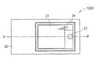
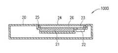
本発明の実施の形態1におけるスピーカシステム1000を、図1A、図1Bおよび図2を参照して説明する。図1Aはスピーカシステム1000の平面図であり、図1Bは図1Aに示す一点鎖線A−Bに沿ったスピーカシステム1000の断面図である。
【0045】
スピーカシステム1000は、画像を表示する表示パネル21と、表示パネル21に表示された画像が透けて見えるように配置された透明パネル24と、振動板45(図2)を有し電気信号に応じて振動板45を振動させることにより音を放射する電気機械音響変換器22と、透明パネル24の周辺部に接続された弾性体25と、透明パネル24および表示パネル21を支持する筐体20とを備える。
【0046】
スピーカシステム1000において、表示パネル21と透明パネル24との間には空間26が形成されている。空間26は閉空間であることが望ましい。筐体20には音孔23が形成されている。筐体20は、電気機械音響変換器22から放射された音を空間26に伝達する音響伝達部材として機能する。透明パネル24の周辺部は弾性体25で支持されており、透明パネル24は、音孔23を介して電気機械音響変換器22から空間26に伝達された音によって振動することができる。スピーカシステム1000では、筐体20は弾性体25を介して透明パネル24を支持する。透明パネル24の面積は、振動板45の面積より大きい。表示パネル21は例えば液晶ディスプレイである。透明パネル24は、可視光を透過する材料であるガラス、アクリル等から形成される。
【0047】
図2は、電気機械音響変換器22の断面図である。本実施の形態の電気機械音響変換器22は動電形スピーカである。
【0048】
電気機械音響変換器22は、壺型のヨーク40と、ヨーク40の中央部に設けられたマグネット41と、マグネット41の上面に設けられたプレート42と、ヨーク40とプレート42との間の磁気空隙43に挿入されたボイスコイル44と、ボイスコイル44に接続された振動板45と、振動板45の周辺部を支持する筐体46とを備える。ヨーク40は筐体46の中央部に設けられている。筐体46は、振動板45と音孔23とが対向するように、筐体20に接続される。
【0049】
次に、スピーカシステム1000の動作について説明する。
【0050】
磁気空隙43に挿入されたボイスコイル44に電気信号が印加されると、ボイスコイル44に駆動力が発生し、ボイスコイル44に接続された振動板45が振動して音が発生する。振動板45から発生した音は音孔23を介して空間26に伝えられる。外周部を弾性体25で支持された透明パネル24は、空間26に伝えられた音の圧力により駆動されて振動し、音を発生する。
【0051】
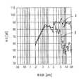
図3は、スピーカシステム1000の音圧−周波数特性の測定結果を示す。測定においては、電気機械音響変換器22として口径φ18mmの動電形スピーカを、透明パネル24としてサイズが長さ60mm、幅35mm、厚さ1.7mmの透明アクリル板を用いた。スピーカシステム1000から0.1m離れた位置にマイクを設置し、電気機械音響変換器22に0.1Wの電力を印加して測定した。
【0052】
図3に示す特性Iは、透明パネル24がない状態で、電気機械音響変換器22単独から放射される音の特性を示す。特性IIは、透明パネル24がある状態で、透明パネル24から放射される音の特性を示す。特性IIは、特性Iと比較して3kHz以上の高音域で音圧レベルが低下している。
【0053】
しかし、この音圧レベルの低下は、空間26の音響容積を調整することにより改善することができる。また、この音圧レベルの低下は、振動パネル24の重量を調整することによっても改善することができる。即ち、空間26の表示パネル21と透明パネル24との間の幅を狭くすれば音響容積が小さくなって高音域の音圧レベルを上昇させることが可能である。また、透明パネル24の重量を軽くすることによっても高音域の音圧レベルを上昇させることが可能である。透明パネル24として比重の小さな材料を用いたり、透明パネル24の材厚を調整することにより、高音域特性を制御することが可能である。必要とする再生帯域幅に応じて空間26の幅および透明パネル24の重量は調整される。
【0054】
また、電気機械音響変換器22として用いた口径φ18mmの動電形スピーカの振動板45として、厚さ20μm、重量約6mgのアクリル材料を用いた。また、ボイスコイル44として線径φ0.055mm、重量25mgの銅線を用い、ボイスコイル44は口径φ8mmであった。
【0055】
透明パネル24(長さ60mm、幅35mm、厚さ1.7mmの透明アクリル材料)の重量は約4200mgであった。透明パネル24の重量と振動板45およびボイスコイル44の合計重量との比は4200mg/(6mg+25mg)=約135倍となる。透明パネル24の重量は振動板45およびボイスコイル44の合計重量の135倍であるので、ボイスコイルを透明パネル24に接続して、ボイスコイルで透明パネル24を直接振動させようとしても、透明パネル24をほとんど振動させることができない。その結果、ボイスコイルで透明パネル24を直接振動させようとしても、透明パネル24からはほとんど音が発生しない。
【0056】
一方、本発明のスピーカシステム1000では、重量の大きい透明パネル24を小さい力で十分に振動させることができる。スピーカシステム1000において、ボイスコイル44が振動板45を駆動することにより振動板45が空間26に圧力を加えると、空間26に加えられた圧力が透明パネル24に伝わることにより透明パネル24は駆動する。ここで、振動板45の有効振動面積をS1、透明パネル24の振動面積をS2、透明パネル24の重量をM2としたとき、音響変成器の効果により、ボイスコイル44からみた透明パネル24の等価重量はM2/(S2/S1)2となる。
【0057】
上記の例では、振動板45の有効振動面積S1=98.5mm、透明パネル24の振動面積S2=2100mm2となる(振動板45のエッジ部のほぼ中央までを振動の有効半径とすると、振動板45の外形はφ18mmであるが有効半径は5.6mmとなる)。ボイスコイル44からみた透明パネル24の等価重量は、4200mg/(2100mm2/98.5mm2)2=9.2mgとなる。振動板45とボイスコイル44と透明パネル24の等価重量との合計重量は、6mg+25mg+9.2mg=40.2mgとなる。従って、ボイスコイル44は、40.2mgの物体(すなわち、振動板45、ボイスコイル44、透明パネル24)を振動させる力を発生させれば、透明パネル24を振動させることができる。合計重量40.2mgは、振動板45およびボイスコイル44の合計重量31mgの1.3倍程度であるので、ボイスコイル44で発生する力で十分に透明パネル24を振動させることができる。
【0058】
このように、電気機械音響変換器22が空間26を介して透明パネル24を振動させることにより、小さな力で、大きな面積且つ重い重量である透明パネル24を音響再生の振動板として振動させるスピーカシステム1000が実現できる。
【0059】
また、透明パネル24は可視光を透過するため、透明パネル24は、表示パネル21に表示される画像を遮ることなく音響再生を行うことができる。表示パネル21に表示される画像が透けて見えるように透明パネル24が配置されているので、使用者から見た画像が表示される位置と音が放射される位置とを同じにすることができる。使用者から見た画像が表示される位置と音が放射される位置とを同じにすることにより、画像が表示される位置と音が放射される位置とが異なることによる違和感を使用者は感じることがない。このようなスピーカシステム1000は、画像や音の信号処理回路を搭載した電子機器および携帯端末装置(パーソナルコンピュータ、テレビ、ゲーム機、携帯電話機等)に搭載される。
【0060】
また、透明パネル24を弾性体で支持することにより、透明パネル24の全面が電気機械音響変換器22で発生した音の圧力で振動するため、再生音量および再生周波数帯域等の音響特性を向上させることができる。特に低音域の再生周波数帯域を広げることができる。
【0061】
なお、実施の形態1では、透明パネル24の周辺部を支持する弾性体25は透明パネル24の下面に設けていたが、弾性体25は透明パネル24の周辺部の側面を覆うように設けられても良い。また、透明パネル24、表示パネル21、弾性体25、筐体20および電気機械音響変換器22とに囲まれた空間26は、電気機械音響変換器22の振動板45から放射された音が漏れないように高い気密性を保つことが望ましい。
【0062】
また、実施の形態1では、電気機械音響変換器22として動電形スピーカを用いたが、電磁形スピーカ、圧電形スピーカ、静電形スピーカ等、振動板から音を放射するスピーカであればどのようなスピーカを用いても、同様な効果が得られる。また、電気機械音響変換器22の外形形状は丸型であってもよいが、楕円あるいは長方形として表示パネル21の搭載スペースを広く確保することで表示パネル21を大きくすることが出来る。
【0063】
(実施の形態2)
本発明の実施の形態2におけるスピーカシステム1100を、図4および図5を参照して説明する。図4はスピーカシステム1100の平面図であり、図5は図4に示す一点鎖線C−Dに沿ったスピーカシステム1100の断面図である。
【0064】
スピーカシステム1100は、画像を表示する表示パネル21と、表示パネル21に表示された画像が透けて見えるように配置された透明パネル224と、表示パネル21と透明パネル224との間に画像が透けて見えるように配置された基板227と、振動板45(図2)を有し電気信号に応じて振動板45を振動させることにより音を放射する電気機械音響変換器22と、透明パネル224の周辺部と基板227の周辺部とを接続するスペーサ225と、基板227を支持する筐体220とを備える。
【0065】
スピーカシステム1100において、基板227と透明パネル224との間には空間226が形成されている。空間226は閉空間であることが望ましい。基板227には音孔223が形成されている。基板227は、電気機械音響変換器22から放射された音を空間226に伝達する音響伝達部材として機能する。透明パネル224は、音孔223を介して電気機械音響変換器22から空間226に伝達された音によって振動することができる。基板227はスペーサ225を介して透明パネル224を支持する。透明パネル224の面積は、振動板45の面積より大きい。本実施の形態では、透明パネル224はフィルムであり、例えば可視光を透過する樹脂材料であるPET(ポリエチレンテレフタレート)、アクリル等から形成される。
【0066】
電気機械音響変換器22の構成要素については実施の形態1で説明したとおりである。本実施の形態において、筐体46は、振動板45と音孔223とが対向するように、基板227に接続される。
【0067】
次に、スピーカシステム1100の動作について説明する。
【0068】
磁気空隙43に挿入されたボイスコイル44に電気信号が印加されると、ボイスコイル44に駆動力が発生し、ボイスコイル44に接続された振動板45が振動して音が発生する。振動板45から発生した音は音孔223を介して空間226に伝えられる。周辺部をスペーサ225で支持された透明パネル224は、空間226に伝えられた音の圧力により駆動されて振動し、音を発生する。
【0069】
図6は、スピーカシステム1100の音圧−周波数特性の測定結果を示す。測定においては、電気機械音響変換器22として口径φ18mmの動電形スピーカを、透明パネル224としてサイズが長さ90mm、幅60mm、厚さ0.1mmの透明PET(ポリエチレンテレフタレート)樹脂板を用いた。スピーカシステム1100から0.1m離れた位置にマイクを設置し、電気機械音響変換器22に0.1Wの電力を印加して測定した。
【0070】
図6に示す特性IIIは、透明パネル224がない状態で、電気機械音響変換器22単独から放射される音の特性を示す。特性IVは、透明パネル224がある状態で、透明パネル224から放射される音の特性を示す。
【0071】
また、電気機械音響変換器22として用いた口径φ18mmの動電形スピーカの振動板45として、厚さ20μm、重量約6mgのアクリル材料を用いた。また、ボイスコイル44として線径φ0.055mm、重量25mgの銅線を用い、ボイスコイル44は口径φ8mmであった。
【0072】
透明パネル224(長さ90mm、幅60mm、厚さ0.1mmの透明PET材料)の重量は約700mgであった。透明パネル224の重量と振動板45およびボイスコイル44の合計重量との比は700mg/(6mg+25mg)=約22.6倍となる。透明パネル224の重量は振動板45およびボイスコイル44の合計重量の22.6倍であるので、ボイスコイルを透明パネル224に接続して、ボイスコイルで透明パネル224を直接振動させようとしても、透明パネル224をほとんど振動させることができない。その結果、ボイスコイルで透明パネル224を直接振動させようとしても、透明パネル224からはほとんど音が発生しない。
【0073】
一方、本発明のスピーカシステム1100では、重量の大きい透明パネル224を小さい力で十分に振動させることができる。スピーカシステム1100において、ボイスコイル44が振動板45を駆動することにより振動板45が空間226に圧力を加えると、空間226に加えられた圧力が透明パネル224に伝わることにより透明パネル224は駆動する。実施の形態1で説明したように、振動板45の有効振動面積をS1、透明パネル224の振動面積をS2、透明パネル224の重量をM2としたとき、音響変成器の効果により、ボイスコイル44からみた透明パネル224の等価重量はM2/(S2/S1)2となる。
【0074】
上記の例では、振動板45の有効振動面積S1=98.5mm、透明パネル224の振動面積S2=5400mm2となる(実施の形態1で説明したように振動板45の振動有効半径は5.6mmとなる)。ボイスコイル44からみた透明パネル224の等価重量は、700mg/(5400mm2/98.5mm2)2=0.2mgとなる。振動板45およびボイスコイル44の重量と透明パネル224の等価重量との合計重量は、6mg+25mg+0.2mg=31.2mgとなる。合計重量31.2mgは、振動板45およびボイスコイル44の合計重量31mgとほぼ同じであるので、ボイスコイル44で発生する力で十分に透明パネル224を振動させることができる。
【0075】
このように、電気機械音響変換器22が空間226を介して透明パネル224を振動させることにより、小さな力で、大きな面積且つ重い重量である透明パネル224を音響再生の振動板として振動させるスピーカシステム1100が実現できる。
【0076】
また、透明パネル224および透明な基板227は可視光を透過するため、透明パネル224は、表示パネル21に表示される画像を遮ることなく音響再生を行うことができる。表示パネル21に表示される画像が透けて見えるように透明パネル224が配置されているので、使用者から見た画像が表示される位置と音が放射される位置とを同じにすることができる。使用者から見た画像が表示される位置と音が放射される位置とを同じにすることにより、画像が表示される位置と音が放射される位置とが異なることによる違和感を使用者は感じることがない。このようなスピーカシステム1100は、画像や音の信号処理回路を搭載した電子機器および携帯端末装置(パーソナルコンピュータ、テレビ、ゲーム機、携帯電話機等)に搭載される。
【0077】
また、スピーカシステム1100では、表示パネル21と透明パネル224との間に基板227が配置される。表示パネル21を外部衝撃から保護する機能を基板227が果たすことで、透明パネル224を薄くすることができ、透明パネル224の再生音量および再生周波数帯域等の音響特性を向上させることができる。特に低音域の再生周波数帯域を広げることができる。
【0078】
さらに、スピーカシステム1100の製造工程において、透明パネル224と基板227とを用いて空間226を予め形成しておくことにより、空間226を形成するための透明パネル224および基板227と表示パネル21との間の精密な位置合わせが不要となる。このことは、スピーカシステム1100を電子機器および携帯端末装置への搭載する際の製造工程の簡略化につながる。
【0079】
また、透明パネル224、基板227、スペーサ225および電気機械音響変換器22とに囲まれた空間226は、電気機械音響変換器22の振動板45から放射された音が漏れないように高い気密性を保つことが望ましい。高い気密性を保つために、例えば透明パネル224、基板227、スペーサ225および電気機械音響変換器22は互いに接着される。
【0080】
なお、実施の形態2では、電気機械音響変換器22として動電形スピーカを用いたが、電磁形スピーカ、圧電形スピーカ、静電形スピーカ等、振動板から音を放射するスピーカであればどのようなスピーカを用いても、同様な効果が得られる。また、電気機械音響変換器22の外形形状は丸型であってもよいが、楕円あるいは長方形として表示パネル21の搭載スペースを広く確保することで表示パネル21を大きくすることが出来る。
【0081】
(実施の形態3)
本発明の実施の形態3におけるスピーカシステム1200を、図7A、図7Bおよび図8を参照して説明する。図7Aはスピーカシステム1200の平面図であり、図7Bは図7Aに示す一点鎖線E−Fに沿ったスピーカシステム1200の断面図である。
【0082】
スピーカシステム1200は、画像を表示する表示パネル21と、表示パネル21に表示された画像が透けて見えるように配置された透明パネル34と、振動板52(図8)を有し電気信号に応じて振動板52を振動させることにより音を放射する電気機械音響変換器32と、電気機械音響変換器32に接続された音響管33と、透明パネル34および表示パネル21を支持する筐体20とを備える。
【0083】
スピーカシステム1200において、表示パネル21と透明パネル34との間には空間37が形成されている。空間37は閉空間であることが望ましい。筐体20には音響管33の開口部36が接続される。音響管33は、電気機械音響変換器32から放射された音を空間37に伝達する音響伝達部材として機能する。透明パネル34の周辺部35は、透明パネル34の中央部よりも薄い。周辺部35は筐体20で支持されており、透明パネル34は、音響管33を介して電気機械音響変換器32から空間37に伝達された音によって振動することができる。透明パネル34の面積は、振動板52の面積より大きい。透明パネル34は、可視光を透過する材料であるガラス、アクリル等から形成される。
【0084】
図8は電気機械音響変換器32の断面図である。本実施の形態の電気機械音響変換器32は圧電形スピーカである。電気機械音響変換器32を圧電形スピーカとすることで、電気機械音響変換器32を薄型にすることができる。
【0085】
電気機械音響変換器32は、圧電素子50、51と、圧電素子50、51を両面に貼り付けた振動板52と、入力端子57および振動板52に接続された電気入力のリード線53と、入力端子56および圧電素子51に接続されたリード線54と、入力端子56および圧電素子50に接続されたリード線55と、
振動板52の周辺部を支持する筐体58とを備える。振動板52は、リン青銅、ステンレス等の導電材料を含み、中間電極として機能する。筐体58は音響管33に接続されている。
【0086】
次に、スピーカシステム1200の動作について説明する。
【0087】
入力端子56、57に電気信号が印加されると、振動板52の両面に接合された圧電素子50、51に屈曲振動が生じて、振動板52および圧電素子50、51から音が発生する。この音は音響管33を通過してその開口部36から空間37に伝達される。周辺部35を筐体20に支持された透明パネル34は、空間37に伝達された音の圧力により駆動されて振動し、音を発生する。このような透明パネル34が音を発生する動作は、実施の形態1の透明パネル24が音を発生する動作とほぼ同様である。
【0088】
実施の形態1のスピーカシステム1000と異なる点として、本実施の形態のスピーカシステム1200においては、電気機械音響変換器32から放射された音を空間37に伝達する音響伝達部材として音響管33が用いられる。これにより、電気機械音響変換器32を表示パネル21の背面側に配置可能となる。電気機械音響変換器32を表示パネル21の背面側に配置することにより、表示パネル21の設置スペースを広くすることができ、表示パネル21の大きさを大きくすることができる。また、音響管33の開口部36を長方形形状として、開口部36に隣接する表示パネル21の1辺と開口部36の長手方向とを平行にすることにより、表示パネル21のさらなる大型化が可能となる。
【0089】
なお、透明パネル34の周辺部35は、透明パネル34の中央部と同じ材料で一体形成されてもよいし、透明パネル34の中央部と異なる材料で形成されて透明パネル34の中央部に固着されてもよい。
【0090】
さらに、透明パネル34は周辺部35だけでなく全面をフィルムとしても良く、この場合、電気機械音響変換器32から放射される音によりフィルムの透明パネル34全体が駆動される。
【0091】
なお、本実施の形態では、電気機械音響変換器32として圧電形スピーカを用いたが、電磁形スピーカ、動電形スピーカ、静電形スピーカ等、振動板から音を放射するスピーカであればどのようなスピーカを用いても、同様な効果が得られる。
【0092】
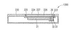
次に、本発明の実施の形態2のスピーカシステム1100の改変例であるスピーカシステム1300を、図9A、図9Bを参照して説明する。図9Aはスピーカシステム1300の平面図であり、図9Bは図9Aに示す一点鎖線G−Hに沿ったスピーカシステム1300の断面図である。
【0093】
スピーカシステム1300は、電気機械音響変換器22の代わりに、上述した電気機械音響変換器32と、電気機械音響変換器32に接続された音響管33とを備える。基板227の音孔223に音響管33の開口部36が接続される。音響管33は、電気機械音響変換器32から放射された音を空間37に伝達する音響伝達部材として機能する。
【0094】
次に、スピーカシステム1300の動作について説明する。
【0095】
図8、図9Aおよび図9Bを参照して、入力端子56、57に電気信号が印加されると、振動板52の両面に接合された圧電素子50、51に屈曲振動が生じて、振動板52および圧電素子50、51から音が発生する。この音は音響管33を通過してその開口部36から空間226に伝達される。透明パネル224は、空間226に伝達された音の圧力により駆動されて振動し、音を発生する。
【0096】
スピーカシステム1300においては、電気機械音響変換器32から放射された音を空間226に伝達する音響伝達部材として音響管33が用いられる。これにより、電気機械音響変換器32を表示パネル21の背面側に配置可能となる。電気機械音響変換器32を表示パネル21の平面方向以外の位置に配置することにより、表示パネル21の設置スペースを広くすることができ、表示パネル21の大きさを大きくすることができる。また、音響管33の開口部36を長方形形状として、開口部36に隣接する表示パネル21の1辺と開口部36の長手方向とを平行にすることにより、表示パネル21のさらなる大型化が可能となる。
【0097】
なお、電気機械音響変換器32として圧電形スピーカを用いたが、上述したように、電磁形スピーカ、動電形スピーカ、静電形スピーカ等、振動板から音を放射するスピーカであればどのようなスピーカを用いても、同様な効果が得られる。
【0098】
(実施の形態4)
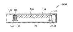
本発明の実施の形態4におけるスピーカシステム1400を、図10A、図10Bを参照して説明する。図10Aはスピーカシステム1400の平面図であり、図10Bは図10Aに示す一点鎖線I−Jに沿ったスピーカシステム1400の断面図である。スピーカシステム1400は、基本的には実施の形態3のスピーカシステム1200に複数の電気機械音響変換器を設けた構成である。
【0099】
スピーカシステム1400は、画像を表示する表示パネル21と、表示パネル21に表示された画像が透けて見えるように配置された透明パネル138と、振動板52(図8)をそれぞれ有し電気信号に応じて振動板52を振動させることにより音を放射する電気機械音響変換器32および132と、電気機械音響変換器32にそれぞれ接続された音響管33および133と、透明パネル138および表示パネル21を支持する筐体130とを備える。
【0100】
表示パネル21と透明パネル138との間には空間139が形成されている。空間139は閉空間であることが望ましい。筐体130には音響管33および133それぞれの開口部36および136が接続される。音響管33および133はそれぞれ、電気機械音響変換器32および132から放射された音を空間139に伝達する音響伝達部材として機能する。透明パネル138の周辺部は筐体130で支持されており、透明パネル138は、音響管33および133を介して電気機械音響変換器32および132から空間139に伝達された音によって振動することができる。透明パネル138の面積は、振動板52の面積より大きい。透明パネル138はフィルムであり、可視光を透過するPET(ポリエチレンテレフタレート)等から形成される。
【0101】
次に、スピーカシステム1400の動作ついて説明する。
【0102】
実施の形態3のスピーカシステム1200と異なる点として、本実施の形態ではスピーカシステム1400は、複数の電気機械音響変換器32および132と複数の音響管33および133を備える。また、透明パネル138の全面がフィルムである。
【0103】
電気機械音響変換器132の構成要素は電気機械音響変換器32の構成要素と同じである。電気機械音響変換器32の動作は実施の形態3で説明したとおりであり、電気機械音響変換器132も同様に動作する。音響管33および133はそれぞれ電気機械音響変換器32および132に接続される。音響管33および133の開口部は、それぞれ空間139の異なる位置に結合されている。電気機械音響変換器132から放射された音は音響管133を介して空間139に伝達される。透明パネル138は空間139に伝達された音の圧力により振動して音を発生する。
【0104】
例えば、電気機械音響変換器32に右チャンネルのオーディオ情報を示す電気信号を入力し、電気機械音響変換器132に左チャンネルのオーディオ情報を示す電気信号を入力するならば、開口部36からは右チャンネルの音が空間139に伝達され、開口部136からは左チャンネルの音が空間139に伝達される。透明パネル138を左右両チャンネルの合成音圧で振動させることにより、ステレオ再生が実現できる。特に、透明パネル138をフィルムとすることで、音の波長が短く指向性の狭い高音域の音により透明パネル138の開口部36および136の真上の部分が振動する。また、波長が長く指向性の広い低音域の音により透明パネル138全体が振動する。このため、空間139内で左右両チャンネルの音が合成されても、音像の広がりに寄与する高音域の音が放出される位置が透明パネル138上で左右に分離されるので、1枚の透明パネル138でありながら、効果的なステレオ再生が可能となる。
【0105】
スピーカシステム1400を、PDA(Personal Digital Assistant)等の比較的大きな表示パネルを備える携帯端末装置に搭載するならば、2つの音響管33および133の開口部36および136が表示パネル21の両端の距離の離れた位置に配置されるため、表示パネル21から放射される音の音像が広くなり、より効果的なステレオ効果が得られる。
【0106】
本実施の形態のスピーカシステム1400は、2つの電気機械音響変換器32および132と2つの音響管33および133とを備えたが、電気機械音響変換器および音響管を3つ以上備えてもよい。複数の電気機械音響変換器それぞれに複数の音響管が接続される。複数の音響管の開口部は、それぞれ空間139の異なる位置に結合される。この場合、複数の電気機械音響変換器からの音により透明パネル138が振動するため、より大きな音量の音が透明パネル138より放射される。
【0107】
さらに、表示パネル21の上下左右方向にそれぞれ開口部を形成してもよい。この場合、例えばマルチチャネルの内の1チャネルのオーディオ情報を示す電気信号が入力された電気機械音響変換器から放射された音を伝達する開口部を上下方向に形成することにより、より臨場感のある再生音が得られる。
【0108】
また、電気信号がモノラル信号である場合は、複数の電気機械音響変換器に同じ電気信号が入力されてもよいし、1つの電気機械音響変換器のみに電気信号が入力されてもよい。
【0109】
また、電気機械音響変換器32の代わりに図11に示す電気機械音響変換器232が用いられてもよい。電気機械音響変換器232は、周辺部に錘部141を有する壺型のヨーク140と、ヨーク140の中央部に設けられたマグネット41と、マグネット41の上面に設けられたプレート42と、ヨーク140とプレート42との間の磁気空隙144に挿入されたボイスコイル44と、ボイスコイル44に接続された振動板45と、振動板45の周辺部を支持する筐体147および247と、ヨーク140の周辺部と筐体147の下面とに接続されたサスペンション148とを備える。筐体247には音響管33が接続される。ヨーク140とマグネット41とプレート42とから磁気回路部142が形成される。電気機械音響変換器232では、磁気回路部142がサスペンション148で支持されているので、音響再生と同時にまたは独立して磁気回路部142を振動させて機械振動を発生させることができる。
【0110】
振動板45から音を放射する動作は、実施の形態1において図2を参照して説明したとおりである。
【0111】
磁気回路部142が機械振動する動作について説明する。電気機械音響変換器の振動機能に関しては特開平10−215499号等で開示されているため、ここでは詳細な説明を省略する。ボイスコイル44に電気信号が印加されると、磁気回路部142にボイスコイル44に発生する力と反対方向に力が発生する。磁気回路部142はサスペンション148を介して筐体147に支持されており、磁気回路142の質量とサスペンション148のスティフネスとから機械共振系を構成する。ボイスコイル44に印加する電気信号の周波数が機械共振系の共振周波数とほぼ一致すると磁気回路部142は大きく振動する。この振動はサスペンション148を介して筐体147に伝達される。筐体147は筐体247および音響管33を介して筐体130と機械的に結合されているため、磁気回路部142の振動は筐体130に伝達され、筐体130を振動させる。
【0112】
このように、電気機械音響変換器232は音響再生と機械振動発生の2機能を有する。例えば、本発明のスピーカシステム1400を、受信機能を有する携帯電話等の携帯端末装置に用いるならば、着信をメロディー音等の音響信号で知らせるスピーカとしての機能と、着信を振動の体感で知らせるバイブレータとしての機能を1つのユニットで行うことのできる携帯端末装置が実現できる。
【0113】
また、電気機械音響変換器232を含むスピーカシステム1400が搭載された電子機器を用いてゲーム等を行う場合、臨場感のある効果音と共に振動機能により体感上の効果がさらに加わり、迫力のあるゲームが楽しめる。
【0114】
また、上述したように電気信号がモノラル信号の場合でも、透明パネル138からの音響再生のみでなく機械振動機能による体感作用が得られる。
【0115】
また、電気機械音響変換器132の代わりに電気機械音響変換器232が用いられてもよい。また、実施の形態1〜3における電気機械音響変換器22および32の代わりに電気機械音響変換器232が用いられてもよい。
【0116】
次に実施の形態1のスピーカシステム1100の改変例であるスピーカシステム1500を図12を参照して説明する。
【0117】
スピーカシステム1500は、スピーカシステム1100の構成要素に加えて、図9Bに示す電気機械音響変換器32および音響管33をさらに備える。基板227の代わりに設けられた基板127には音孔123および音孔323が形成されている。音孔123には電気機械音響変換器22が接続され、音孔323には音響管33の開口部36が接続されている。音響管33は電気機械音響変換器32に接続されている。本実施の形態において、透明パネル224はフィルムである。基板127と透明パネル224との間には空間126が形成されている。空間126は閉空間であることが望ましい。
【0118】
次に、スピーカシステム1500の動作について説明する。
【0119】
電気機械音響変換器22および32の動作は実施の形態1および3で説明したとおりである。電気機械音響変換器22から放射された音は音孔123を介して空間126に伝達される。電気機械音響変換器32から放射された音は音響管33を介して空間126に伝達される。透明パネル224は空間126に伝達された音の圧力により振動して音を発生する。
【0120】
例えば、電気機械音響変換器22に右チャンネルのオーディオ情報を示す電気信号を入力し、電気機械音響変換器32に左チャンネルのオーディオ情報を示す電気信号を入力するならば、電気機械音響変換器22からは右チャンネルの音が空間126に伝達され、電気機械音響変換器32からは左チャンネルの音が空間126に伝達される。透明パネル224を左右両チャンネルの合成音圧で振動させることにより、ステレオ再生が実現できる。透明パネル224はフィルムであるので、音の波長が短く指向性の狭い高音域の音により透明パネル224の開口部123および323の真上の部分が振動する。また、波長が長く指向性の広い低音域の音により透明パネル224全体が振動する。このため、空間126内で左右両チャンネルの音が合成されても、音像の広がりに寄与する高音域の音が放出される位置が透明パネル224上で左右に分離されるので、1枚の透明パネル224でありながら、効果的なステレオ再生が可能となる。
【0121】
また、音響管33を電気機械音響変換器32の中心から外れた位置に接続することで、筐体220内の空きスペースに電気機械音響変換器32を効率よく設置することが可能となる。また、筐体220内の空きスペースをより効率よく形成することが可能となり、この空きスペースには受信回路等の電気回路を設けることができる。
【0122】
なお、電気機械音響変換器22および32は両方とも動電形スピーカであってもよいし、両方とも圧電形スピーカであってもよい。
【0123】
また、電気機械音響変換器22および32の代わりにそれぞれ電気機械音響変換器232が用いられてもよい。
【0124】
また、電気機械音響変換器22と音孔123との間に音響管が設けられてもよい。また、音響管33を省略し、電気機械音響変換器32が基板127に直接接続されてもよい。
【0125】
また、本実施の形態のスピーカシステム1500は、2つの電気機械音響変換器22および32と1つの音響管33とを備えたが、電気機械音響変換器および音響管を3つ以上備えてもよい。
【0126】
また、電気機械音響変換器22、32および132として、動電形スピーカ、電磁形スピーカ、圧電形スピーカ、静電形スピーカ等、振動板から音を放射するスピーカであればどのようなスピーカが用いられてもよい。
【0127】
スピーカシステム1400および1500において、電気信号は、受話音、着信音、複数チャネルのオーディオ情報の内の少なくとも1つを示し、電気信号が受話音および着信音の内の少なくとも一方を示す場合は、複数の電気機械音響変換器22、32、132に電気信号が入力され、電気信号が複数チャネルのオーディオ情報を示す場合は、複数の電気機械音響変換器22、32、132にはそれぞれ異なるチャネルのオーディオ情報を示す電気信号が入力される。
【0128】
(実施の形態5)
本発明の実施の形態5における携帯端末装置2000を図13および図14を参照して説明する。図13は、携帯端末装置2000の一部切り欠き図である。図14は、携帯端末装置2000の内部を示すブロック図である。
【0129】
本実施の形態では、携帯端末装置2000が携帯電話機であるとして説明するが、携帯端末装置2000は携帯電話機に限定されない。携帯端末装置2000は、例えばPDA(Personal Digital Assistant)、ポケットベルおよび腕時計等であってもよい。
【0130】
携帯端末装置2000は、第1の筐体100と、受信回路等を内蔵する第2の筐体101と、第2の筐体101に取付けられた受信用アンテナ102と、スピーカシステム1201とを備える。第1の筐体100は電気回路やコネクター等(図示せず)を内蔵する。スピーカシステム1201は、実施の形態3で示したスピーカシステム1200の改変例である。スピーカシステム1201は、表示パネル21の代わりに表示パネル221を備える。表示パネル221は例えば液晶ディスプレイであり、表示パネル21と同様の機能を有する。スピーカシステム1201では、表示パネル221および透明パネル34の周辺部35は第2の筐体101に支持される。表示パネル221と透明パネル34との間には空間237が形成されている。空間237は閉空間であることが望ましい。表示パネル221は、表示パネル221に表示される画像を外部から見ることができるように第2の筐体101に支持される。
【0131】
次に、携帯端末装置2000の動作について説明する。
【0132】
スピーカシステム1201の動作は、実施の形態3で説明したスピーカシステム1200の動作と同様である。
【0133】
電気機械音響変換器32(図14)に受話音を示す電気信号を印加すると透明パネル34から受話音が再生される。この場合、スピーカシステム1201は受話音再生用のスピーカであるレシーバとしての機能を果たす。
【0134】
また、電気機械音響変換器32に着信を知らせる着信音、音楽、音声またはゲームの効果音等を示す電気信号を印加するならば、透明パネル34から着信音、音楽、音声または効果音等が再生される。この場合、スピーカシステム1201は、拡声用のスピーカとして機能する。
【0135】
また、携帯端末装置2000が例えばテレビ電話の機能を有する電話機であるならば、画像信号を表示パネル221に印加することにより話し相手の顔が表示パネル221に再生され、同時に、音声信号が示す話し相手の声が透明パネル34から再生される。
【0136】
実施の形態1での説明と同様に、本発明のスピーカシステム1201は、小さな力で大きな面積且つ重い重量である透明パネル34を十分に振動させることができる。このため、携帯端末装置2000が大型の表示パネル221を搭載し、透明パネル34の面積が広くなっても、透明パネル34を十分に振動させることができる。また、音の放射面が表示パネルと同じ面であるため、使用者から見た画像が表示される位置と音が放射される位置とを同じにすることができるので、よりリアルな音響再生が可能となる。このため、音と映像の同時再生に最適な携帯端末装置が実現できる。
【0137】
また、透明パネル34を受話音再生用レシーバの振動板として動作させた場合、受話音は透明パネル34全面から再生されているため、使用者の耳が面積の広い透明パネル34のどの位置に接触しても受聴が可能である。このため、使用者の耳の位置を一点に一致させる必要がないので、使用者の耳が音の発生源からずれてしまうことはない。特に高齢者には受話音の聴き取りが容易な携帯端末装置を実現できる。
【0138】
次に、図14を参照して、携帯端末装置2000の動作についてさらに説明する。
【0139】
携帯端末装置2000は、アンテナ102が受信した無線信号に基づいて電気信号を出力する信号出力部120を備える。信号出力部120は、無線信号処理部121と電気信号増幅部122とを備える。
【0140】
アンテナ102は、外部(例えば携帯電話の中継局)から送られてきた無線信号を受信する。この無線信号は、着信、受話音、音楽および画像等を示す。
【0141】
まず、アンテナ102が着信を示す無線信号を受信すると、使用者に着信を知らせるために、無線信号処理部121は着信を示す着信音信号を出力する。着信音信号は電気信号増幅部122で増幅されて電気機械音響変換器32に印加され、透明パネル34は着信音を再生する。着信音信号は予め設定された呼び出し音を示す信号やデータ配信等により得られたオーディオ信号であり得る。受信者が着信を知り携帯端末装置2000を受話可能状態にすると、無線信号処理部121は受話音(送信者の話し声)を示す受話音信号を出力する。受話音信号は電気信号増幅部122で増幅されて電気機械音響変換器32に印加され、透明パネル34は受話音を再生する。
【0142】
この場合、使用者は、携帯端末装置2000を通常の携帯電話機のように透明パネル34に耳を付けて使用する方法と、電気信号増幅部122の増幅率を上げて、再生音量を大きくして携帯端末装置2000から離れた位置で会話を行うハンズフリー電話機として使用する方法とが選択できる。後者のハンズフリー電話機として使用する場合、双方の電話機がカメラを搭載し、テレビ電話の機能を有するならば、画像信号が入力された表示パネル221に映し出される相手の顔を見ながら会話をすることができる。画像信号は、動画、静止画、文字情報等の画像を示す。アンテナ102が画像を示す無線信号を受信し、信号出力部120が画像信号を表示パネル221へ出力することにより、表示パネル221に画像が映し出される。携帯端末装置2000をハンズフリー電話機として使用する場合、スピーカシステム1201は拡声用のスピーカとして機能する。また、スピーカシステム1201を拡声用のスピーカとして機能させることで、例えばインターネットでダウンロードした音楽信号の再生が可能となる。
【0143】
また、画像と音の同時再生での応用としては、楽曲のプロモーションビデオの再生やゲーム機としての使用が挙げられる。
【0144】
なお、携帯端末装置2000はスピーカシステム1201の代わりに実施の形態1のスピーカシステム1000を備えてもよい。
【0145】
(実施の形態6)
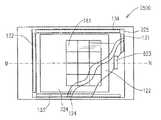
本発明の実施の形態6における携帯端末装置2100を図15および図16を参照して説明する。図15は、携帯端末装置2100の一部切り欠き図である。図16は、携帯端末装置2100の内部を示すブロック図である。
【0146】
本実施の形態では、携帯端末装置2100が携帯電話機であるとして説明するが、携帯端末装置2100は携帯電話機に限定されない。
【0147】
携帯端末装置2100は、第1の筐体100と、受信回路等を内蔵する第2の筐体101と、第2の筐体101に取付けられた受信用アンテナ102と、スピーカシステム1301とを備える。第1の筐体100は電気回路やコネクター等(図示せず)を内蔵する。スピーカシステム1301は、実施の形態3で示したスピーカシステム1300の改変例である。スピーカシステム1301は、表示パネル21の代わりに表示パネル221を備える。スピーカシステム1301では、表示パネル221および基板227は第2の筐体101に支持される。表示パネル221は、表示パネル221に表示される画像を外部から見ることができるように第2の筐体101に支持される。
【0148】
次に、携帯端末装置2100の動作について説明する。本実施の形態の携帯端末装置2100と実施の形態5に示す携帯端末装置2000との差異は、携帯端末装置2100はスピーカシステム1201の代わりにスピーカシステム1301を備える点である。端末装置2100と携帯端末装置2000とは、スピーカシステムが異なる点以外は同様の構成であり、端末装置2100の動作は上述した携帯端末装置2000の動作と同様である。スピーカシステム1301は基板227を備える。基板227から得られる効果は実施の形態2で説明したとおりである。スピーカシステム1301の動作は、実施の形態3で説明したスピーカシステム1300の動作と同様である。
【0149】
電気機械音響変換器32(図16)に受話音を示す電気信号を印加すると透明パネル224から受話音が再生される。この場合、スピーカシステム1301は受話音再生用のスピーカであるレシーバとしての機能を果たす。
【0150】
また、電気機械音響変換器32に着信を知らせる着信音、音楽、音声またはゲームの効果音等を示す電気信号を印加するならば、透明パネル224から着信音、音楽、音声または効果音等が再生される。この場合、スピーカシステム1301は、拡声用のスピーカとして機能する。
【0151】
また、携帯端末装置2100が例えばテレビ電話の機能を有する電話機であるならば、画像信号を表示パネル221に印加することにより話し相手の顔が表示パネル221に再生され、同時に、音声信号が示す話し相手の声が透明パネル224から再生される。
【0152】
図16に示すように携帯端末装置2100は、アンテナ102が受信した無線信号に基づいて電気信号を出力する信号出力部120を備える。信号出力部120は、無線信号処理部121と電気信号増幅部122とを備える。携帯端末装置2100が無線信号を受信してスピーカシステム1301を駆動する動作は、上述した携帯端末装置2000の動作と同様である。
【0153】
なお、携帯端末装置2100はスピーカシステム1301の代わりに実施の形態1のスピーカシステム1000を備えてもよい。
【0154】
なお、本実施の形態では発明のスピーカシステムを搭載した携帯端末装置を開示したが、本発明のスピーカシステムは表示パネルを有する電子機器であるテレビ、パソコン、ゲーム機、カーナビゲーションシステム等のスピーカシステムとして用いることができる。
【0155】
(実施の形態7)
本発明の実施の形態7における携帯端末装置2200を図17および図18を参照して説明する。図17は、携帯端末装置2200の一部切り欠き図である。図18は、携帯端末装置2200の内部を示すブロック図である。
【0156】
本実施の形態では、携帯端末装置2200が携帯電話機であるとして説明するが、携帯端末装置2200は携帯電話機に限定されない。
【0157】
携帯端末装置2200は、第1の筐体100と、受信回路等を内蔵する第2の筐体101と、第2の筐体101に取付けられた受信用アンテナ102と、スピーカシステム1501とを備える。第1の筐体100は電気回路やコネクター等(図示せず)を内蔵する。スピーカシステム1501は、実施の形態4で示したスピーカシステム1500の改変例である。スピーカシステム1501は、表示パネル21の代わりに表示パネル221を備える。スピーカシステム1501では、表示パネル221および基板227は第2の筐体101に支持される。表示パネル221は、表示パネル221に表示される画像を外部から見ることができるように第2の筐体101に支持される。
【0158】
次に、携帯端末装置2200の動作について説明する。
【0159】
スピーカシステム1501の動作は、実施の形態4で説明したスピーカシステム1500の動作と同様である。
【0160】
電気機械音響変換器22および32(図18)の内の少なくも一方に受話音を示す電気信号を印加すると透明パネル224から受話音が再生される。この場合、スピーカシステム1501は受話音再生用のスピーカであるレシーバとしての機能を果たす。
【0161】
また、電気機械音響変換器22および32の内の少なくとも一方に着信を知らせる着信音、音楽、音声またはゲームの効果音等を示す電気信号を印加するならば、透明パネル224から着信音、音楽、音声または効果音等が再生される。この場合、スピーカシステム1501は、拡声用のスピーカとして機能する。
【0162】
また、電気機械音響変換器22および32に同じ電気信号を印加するならば、電気機械音響変換器を1つのみ備えるスピーカシステムと比較して、消費電力が同じであっても、音圧レベルを向上させることができる。また、上述したように、スピーカシステム1501は複数チャンネルのオーディオ信号を再生することができる。例えば、ステレオ音楽を示すオーディオ信号を再生する場合、電気機械音響変換器22には右チャンネル、電気機械音響変換器32には左チャンネルの音楽信号を印加すると、透明パネル224からはステレオ音楽が再生される。
【0163】
また、携帯端末装置2200が例えばテレビ電話の機能を有する電話機であるならば、画像信号を表示パネル221に印加することにより話し相手の顔が表示パネル221に再生され、同時に、音声信号が示す話し相手の声が透明パネル224から再生される。
【0164】
実施の形態1での説明と同様に、本発明のスピーカシステム1501は、小さな力で大きな面積且つ重い重量である透明パネル224を十分に振動させることができる。このため、携帯端末装置2200が大型の表示パネル221を搭載し、透明パネル224の面積が広くなっても、透明パネル224を十分に振動させることができる。また、音の放射面が表示パネルと同じ面であるため、使用者から見た画像が表示される位置と音が放射される位置とを同じにすることができるので、よりリアルな音響再生が可能となる。
【0165】
次に、図18を参照して、携帯端末装置2200の動作についてさらに説明する。
【0166】
携帯端末装置2200は、アンテナ102が受信した無線信号に基づいて電気信号を出力する信号出力部320を備える。信号出力部320は、無線信号処理部121と電気信号増幅部122および222とを備える。
【0167】
アンテナ102は、外部(例えば携帯電話の中継局)から送られてきた無線信号を受信する。この無線信号は、着信、受話音、音楽および画像等を示す。
【0168】
まず、アンテナ102が着信を示す無線信号を受信すると、使用者に着信を知らせるために、無線信号処理部121は着信を示す着信音信号を出力する。着信音信号は電気信号増幅部122および222の内の少なくとも一方で増幅されて電気機械音響変換器22および32の内の少なくとも一方に印加され、透明パネル224は着信音を再生する。着信音信号は予め設定された呼び出し音を示す信号やデータ配信等により得られたオーディオ信号であり得る。着信音信号がステレオオーディオ信号である場合は、右チャンネルのオーディオ信号は電気信号増幅部122で増幅されて電気機械音響変換器22に印加され、左チャンネルのオーディオ信号は電気信号増幅部222で増幅されて電気機械音響変換器32に印加され、透明パネル224からはステレオ音が再生される。受信者が着信を知り携帯端末装置2200を受話可能状態にすると、無線信号処理部121は受話音(送信者の話し声)を示す受話音信号を出力する。受話音信号は電気信号増幅部122および222の内の少なくとも一方で増幅されて電気機械音響変換器22および32の内の少なくとも一方に印加され、透明パネル224は受話音を再生する。
【0169】
この場合、使用者は、携帯端末装置2200を通常の携帯電話機のように透明パネル224に耳を付けて使用する方法と、電気信号増幅部122および222の増幅率を上げて、再生音量を大きくして携帯端末装置2200から離れた位置で会話を行うハンズフリー電話機として使用する方法とが選択できる。後者のハンズフリー電話機として使用する場合、双方の電話機がカメラを搭載し、テレビ電話の機能を有するならば、画像信号が入力された表示パネル221に映し出される相手の顔を見ながら会話をすることができる。画像信号は、動画、静止画、文字情報等の画像を示す。アンテナ102が画像を示す無線信号を受信し、信号出力部320が画像信号を表示パネル221へ出力することにより、表示パネル221に画像が映し出される。
【0170】
携帯端末装置2200をハンズフリー電話機として使用する場合、スピーカシステム1501は拡声用のスピーカとして機能する。また、スピーカシステム1501を拡声用のスピーカとして機能させることで、例えばインターネットでダウンロードした音楽信号の再生が可能となる。
【0171】
また、画像と音の同時再生での応用としては、楽曲のプロモーションビデオの再生やゲーム機としての使用が挙げられる。
【0172】
携帯端末装置2200において、電気信号は、受話音、着信音、複数チャネルのオーディオ情報の内の少なくとも1つを示し、電気信号が受話音および着信音の内の少なくとも一方を示す場合は、複数の電気機械音響変換器22、32に電気信号が入力され、電気信号が複数チャネルのオーディオ情報を示す場合は、複数の電気機械音響変換器22、32にはそれぞれ異なるチャネルのオーディオ情報を示す電気信号が入力される。
【0173】
なお、携帯端末装置2200はスピーカシステム1501の代わりに実施の形態4のスピーカシステム1400を備えてもよく、この場合のスピーカシステム1400の動作はスピーカシステム1501の動作と同様である。
【0174】
なお、本実施の形態では発明のスピーカシステムを搭載した携帯端末装置を開示したが、本発明のスピーカシステムは表示パネルを有する電子機器であるテレビ、パソコン、ゲーム機、カーナビゲーションシステム等のスピーカシステムとして用いることができる。
【0175】
(実施の形態8)
本発明の実施の形態8における携帯端末装置2300を図19A、図19B図19Cおよび図20を参照して説明する。図19Aは携帯端末装置2300の上面図であり、図19Bは携帯端末装置2300の部分断面図であり、図19Cは携帯端末装置2300の下面図である。
【0176】
本実施の形態では、携帯端末装置2300が携帯電話機であるとして説明するが、携帯端末装置2300は携帯電話機に限定されない。
【0177】
携帯端末装置2300は、第1の筐体100と、第2の筐体201と、第2の筐体201に取り付けられた受信用のアンテナ102と、スピーカシステム1600とを備える。スピーカシステム1600は、実施の形態3で示したスピーカシステム1300の改変例である。スピーカシステム1600は、電気機械音響変換器32の代わりに電気機械音響変換器322を備える。スピーカシステム1600では、基板227および表示パネル221は、第2の筐体201に支持される。第2の筐体201には音孔423が形成されている。第2の筐体201は、受信回路等の電気回路やコネクタ等(図示せず)を内蔵する。
【0178】
電気機械音響変換器322を、図20を参照して説明する。電気機械音響変換器322は、円柱状の第1のマグネット520と、第1のマグネット520を囲むように設けられた環状の第2のマグネット521と、第1のマグネット520と第2のマグネット521とを連結するヨーク522と、第1のマグネット520とヨーク522との間の第1の磁気空隙525に設けられた第1のボイスコイル527と、第2のマグネット521とヨーク522との間の第2の磁気空隙526に設けられた第2のボイスコイル528と、第1のボイスコイル527に接続された第1の振動板529と、第1のマグネット520の第1の振動板529とは反対側に設けられ、第2のボイスコイル528に接続された第2の振動板530と、第1の振動板529と第1のマグネット520との間に設けられた円板状の第1の磁性板523と、第2の振動板530と第2のマグネット521との間に設けられた環状の第2の磁性板524と、第1の振動板529、第2の振動板530および第2のマグネット521を支持する第1の筐体531と、第1の振動板529の第1のマグネット520とは反対側に設けられた第1の振動板529を覆う第2の筐体532とを備える。第2の筐体532に音響管33が接続される。
【0179】
次に、電気機械音響変換器322の動作について説明する。
【0180】
第1の磁気空隙525に挿入された第1のボイスコイル527に電気信号が印加されると、第1のボイスコイル527に駆動力が発生し、第1のボイスコイル527に接続された第1の振動板529が振動して音が発生する。同様に、第2の磁気空隙526に挿入された第2のボイスコイル528に電気信号が印加されると、第2のボイスコイル528に駆動力が発生し、第2のボイスコイル528に接続された第2の振動板530が振動して音が発生する。
【0181】
第1の振動板529から放射された音は音響管33を介して空間226に伝達され、透明パネル224から音が放射される。第2の振動板530から放射された音は音孔423(図19B)を介して外部に放射される。
【0182】
電気機械音響変換器322では、第1の磁気空隙525に挿入された第1のボイスコイル527は第1のマグネット520を用いて駆動され、第2の磁気空隙526に挿入された第2のボイスコイル528は第2のマグネット521を用いて駆動される。第1および第2のボイスコイル527および28をそれぞれ別々のマグネットを用いて駆動するため、第1および第2のボイスコイル527および28に発生する駆動力を大きくすることができる。このため、電気機械音響変換器322は、大きな音を発生させることができる。
【0183】
第1のボイスコイル527および第2のボイスコイル528は互いに独立に駆動可能である。第1の振動板529から放射された着信音および受話音は音響管33を介して空間226に伝達され、透明パネル224から着信音および受話音が放射される。第1の筐体100および第2の筐体101はそれらの接続部200で折り曲げることができるようになっている。第1の筐体100および第2の筐体101が互いに開いているときは、透明パネル224が放射する着信音を使用者は明瞭に聞くことができる。しかし、第1の筐体100および第2の筐体101が互いに閉じているとき(携帯端末機2300を折りたたんだ状態)は、透明パネル224が放射する着信音は第1の筐体100で遮られるので、使用者は着信音を明瞭に聞くことが困難となる。そこで、第1の筐体100および第2の筐体101が互いに閉じているときは、第2の振動板530から着信音を放射することにより、使用者は着信音を明瞭に聞くことができる。折りたたみ式の携帯端末装置においては、折りたたんだ状態での外部への音の放出用と開いた状態での通話用との2つの電気機械音響変換器を備えることが望ましく、電気機械音響変換器の設置スペースは大きかった。本実施の形態の携帯端末機2300では、折りたたんだ状態での外部への音の放出機能と開いた状態での通話機能とを1つの電気機械音響変換器で果たすことができるので、電気機械音響変換器の設置スペースを小さくすることができる。
【0184】
なお、電気機械音響変換器32の代わりに電気機械音響変換器322を備える実施の形態3のスピーカシステム1200がスピーカシステム1600の代わりに用いられてもよい。
【0185】
(実施の形態9)
本発明の実施の形態9における電子機器2400を図21Aおよび図21Bを参照して説明する。図21Aは、電子機器2400の平面図であり、図21Bは図21Aに示す一点鎖線K−Lに沿った電子機器2400の断面図である。
【0186】
本実施の形態では、電子機器2400が携帯端末装置であるPDAであるとして説明するが、電子機器2400はPDA等の携帯端末装置に限定されず、設置型の電子機器であってもよい。
【0187】
電子機器2400は、筐体150と、スピーカシステム1700とを備える。スピーカシステム1700は、実施の形態3のスピーカシステム1200(図7Aおよび図7B)の改変例である。スピーカシステム1700は、表示パネル21および透明パネル34の代わりに表示パネル321および透明パネル234を備える。表示パネル321は表示パネル21と同様の機能を有する。透明パネル234はフィルムであり、透明な樹脂材料であるPET(ポリエチレンテレフタレート)、アクリル等から形成される。表示パネル321と透明パネル234との間には空間337が形成される。空間337は閉空間であることが望ましい。スピーカシステム1700では、表示パネル321および透明パネル234は筐体150に支持される。表示パネル321は、表示パネル321に表示される画像を外部から見ることができるように筐体150に支持される。
【0188】
透明パネル234の表面には導電膜160がコーティングされている。導電膜160は、透明パネル234の表面の抵抗率が均一となるように透明パネル234の表面にコーティングされる。透明パネル234は透明導電体として機能する。導電膜160がコーティングされた透明パネル234の表面の4辺に沿って電極156、157、158および159が設けられる。電子機器2400は、画像信号、音響信号を処理する制御部155をさらに備える。表示パネル321は制御部155により駆動され、操作メニューアイコン161等を表示する。制御部155は、電極156、157、158および159に電圧を印加する。透明パネル234は、タッチパネルとして機能する。
【0189】
次に、電子機器2400の動作を説明する。スピーカシステム1700の動作は、実施の形態3のスピーカシステム1200と同様である。
【0190】
使用者は、表示パネル321に表示される操作メニューアイコン161の1つの位置に対応する透明パネル234の位置を、接触手段であるアイコンクリック専用入力ペン162または使用者の指で接触して加圧する。アイコンクリック専用入力ペン162または使用者の指が透明パネル234に接触すると入力ペン162または使用者の指の静電容量により各電極156、157、158、159から入力ペン162に電流が流れ込む。各電極156、157、158、159の電流の流れによりアイコンクリック専用入力ペン162の透明パネル234への接触が検出される。制御部155は、入力ペン162または使用者の指が接触した透明パネル234上の位置の座標値を、電極156、157、158、159を流れる電流の値から算出する。制御部155は、検出された座標値に対応するメニューアイコン161の内容にしたがって、電子機器2400を予め決められた機能(例えば電子メールの送受信)で動作させる。
【0191】
一般的なタッチパネルの動作は例えば特開平9−265341号に開示される。本発明では、透明パネル234は静電容量方式のタッチパネルとして機能する。即ち、透明パネル234はタッチパネルと音響再生用の透明パネルとを兼用する。タッチパネルを有する電子機器の表示パネルとタッチパネルとの間に空間を形成し、形成した空間に電気機械音響変換器から放射された音を伝達することにより、タッチパネルから音を放射することができる。
【0192】
このように、タッチパネルと音響再生用の透明パネルとを兼用することにより、タッチパネルより音が再生される電子機器が実現され、音響再生のための構成要素を簡略化することができるので、本発明のスピーカシステムの実現が容易となる。タッチパネルは透明で可視光線を透過するので、表示パネルに表示される画像を遮ることはない。
【0193】
なお、本実施の形態では、透明パネル234は静電容量方式のタッチパネルと兼用したが、複数の発光素子と複数の受光素子を備え、発光素子から出射した光が対応する受光素子にまで達することなく遮断されたことを感知して接触手段が接触した透明パネル234の位置を検出する光学方式のタッチパネルと兼用されてもよい。また、透明パネル234は、共振回路を備える接触手段が接触した透明パネル234の位置をループアンテナを用いて検出する電磁誘導方式のタッチパネル、超音波振動子を備えた接触手段が接触した透明パネル234の位置を振動センサを用いて検出する超音波方式のタッチパネル等の他の方式のタッチパネルと兼用しても同様の効果が得られる。いずれの方式の場合にもタッチパネルと振動パネルとを兼用したスピーカシステムを実現することが可能であり、タッチパネルの検出方式はこれらに限定されない。
【0194】
また、スピーカシステム1700の代わりに実施の形態3のスピーカシステム1300が用いられてもよい。
【0195】
(実施の形態10)
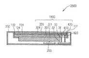
本発明の実施の形態10における電子機器2500を図22Aおよび図22Bを参照して説明する。図22Aは、電子機器2500の平面図であり、図22Bは図22Aに示す一点鎖線M−Nに沿った電子機器2500の断面図である。
【0196】
本実施の形態では、電子機器2500が携帯端末装置であるPDAであるとして説明するが、電子機器2500はPDA等の携帯端末装置に限定されず、設置型の電子機器であってもよい。
【0197】
電子機器2500は、筐体250と、スピーカシステム1800とを備える。スピーカシステム1800は、実施の形態3のスピーカシステム1300(図9Aおよび図9B)の改変例である。スピーカシステム1800は、表示パネル21、透明パネル224および基板227の代わりに表示パネル321、透明パネル324および基板327を備える。透明パネル324はフィルムであり、透明な樹脂材料であるPET(ポリエチレンテレフタレート)、アクリル等から形成される。基板327はポリカーボネイト等の透明な材料から形成される。スピーカシステム1800では表示パネル321は筐体250に支持される。表示パネル321は、表示パネル321に表示される画像を外部から見ることができるように筐体250に支持される。基板327には音孔613が形成され、音孔613には音響管33の開口部36が接続される。
【0198】
基板327の上面に電気抵抗値を有する透明電極114が設けられる。透明パネル324の下面に電気抵抗値を有する透明電極124が設けられる。スペーサ625の短辺側の上面に電気抵抗値検出用の電極131および132が設けられる。電極131および132は透明電極124と接触している。スペーサ625の長辺側の下面に電気抵抗値検出用の電極133および134が設けられる。電極133および134は透明電極114と接触している。透明電極114が設けられた基板327と透明電極124が設けられた透明パネル324との間に空間326が形成される。透明パネル324と基板327とはスペーサ625を用いて接続される。空間326は閉空間であることが望ましい。電子機器2500は、画像信号、音響信号を処理する制御部255をさらに備える。表示パネル321は制御部255により駆動され、操作メニューアイコン161等を表示する。制御部255は、電極131、132、133および134に電圧を印加する。透明パネル324および基板327は、タッチパネルとして機能する。透明電極114には長方形の音孔623が形成されている。
【0199】
次に、電子機器2500の動作を説明する。スピーカシステム1800の動作は、実施の形態3のスピーカシステム1300と同様である。
【0200】
制御部155は、電極156、157、158および159に電圧を印加する。使用者は、表示パネル321に表示される操作メニューアイコン161の1つの位置に対応する透明パネル324の位置を、接触手段であるアイコンクリック専用入力ペン162(図21A)または使用者の指で接触して加圧する。この加圧により透明電極114と透明電極124とが接触して電極131、132、133および134それぞれに電流が流れ、この電流の流れによりアイコンクリック専用入力ペン162の透明パネル324への接触が検出される。制御部255は、電極131、132、133および134それぞれに流れる電流値を検出し、電極131、132、133および134それぞれの間の電気抵抗値を算出する。制御部255は、算出した電気抵抗値から、透明電極114と透明電極124とが接触した位置の座標値を算出する。制御部255は、検出された座標値に対応するメニューアイコン161の内容にしたがって、電子機器2500を予め決められ機能で動作させる。
【0201】
本実施の形態では、透明パネル324は抵抗膜方式のタッチパネルとして機能する。即ち、透明パネル324はタッチパネルと音響再生用の透明パネルとを兼用する。タッチパネルを有する電子機器の表示パネルまたは基板とタッチパネルとの間に予め形成された空間に音響管を接合し、電気機械音響変換器から放射された音を空間に伝達することにより、タッチパネルからの音の放射を容易に実現することができる。抵抗膜方式では、タッチパネルと表示パネルまたは基板との間には必ず隙間が形成されるので、空間の形成は容易である。
【0202】
このように、タッチパネルと音響再生用の透明パネルとを兼用することにより、タッチパネルより音が再生される電子機器が実現され、音響再生のための構成要素を簡略化することができ、スピーカシステムの実現が容易となる。タッチパネルは透明で可視光線を透過するので、表示パネルに表示される画像を遮ることはない。
【0203】
なお、スペーサ625は基板327と透明パネル324との間に音が伝わる空間326を形成するために設けられるが、スペーサ625は接着剤または接着フィルムであってもよい。
【0204】
また、基板327を省略して、表示パネル321上に透明電極114が設けられてもよい。基板327を省略することにより、電子機器2500の構成がさらに簡略化される。スピーカシステム1800の代わりに実施の形態3のスピーカシステム1200が用いられてもよい。
【0205】
なお、本実施の形態では、透明パネル324は抵抗膜方式のタッチパネルと兼用したが、静電容量方式、光学方式、電磁誘導方式、超音波方式等の他の方式のタッチパネルと兼用しても同様の効果が得られる。
【0206】
また、スピーカシステム1800の代わりに実施の形態4のスピーカシステム1400または1500が用いられてもよい。この場合、再生音の音圧レベルは向上して、騒音下でも大きな音量で音声等を再生する電子機器が実現される。
【0207】
(実施の形態11)
実施の形態9および10で説明した電子機器2400および2500では表示パネル321に表示された画像が透けて見えるように透明パネル234および324が用いられたが、タッチパネルを兼用する音響再生用のパネルは、透明でなくてもタッチパネルとして動作することができる。この場合、パネルの背面部から表示パネルは省略されるが、パネルの背面部に電気機械音響変換器からの音を伝達する空間を形成することによりパネルから音を発生させることができる。このような不透明なパネルを用いる本発明の実施の形態について説明する。
【0208】
本実施の形態における電子機器2401を図23Aおよび図23Bを参照して説明する。図23Aは、電子機器2401の平面図であり、図23Bは図23Aに示す一点鎖線K1−L1に沿った電子機器2401の断面図である。
【0209】
電子機器2401は、スピーカシステム1701と、スピーカシステム1701を支持する筐体650とを備える。スピーカシステム1701は、パネル634と、電気機械音響変換器32と、パネル634と筐体650との間に形成された空間637に電気機械音響変換器32から放射された音を伝達する音響管33とを備える。音響管33は、電気機械音響変換器32から放射された音を空間637に伝達する音響伝達部材として機能する。パネル634の周辺部は筐体650に支持され、パネル634は音響管33により電気機械音響変換器32から空間637に伝達された音によって振動する。空間637は閉空間であることが望ましい。
【0210】
スピーカシステム1701は、スピーカシステム1700(図21B)から表示パネル321を省略した構成であり、パネル634は不透明である。電気機械音響変換器32から発生した音によりパネル634が振動してパネル634から音が発生する動作は、スピーカシステム1700において電気機械音響変換器32から発生した音によりパネル234が振動してパネル234から音が発生する動作と同様である。
【0211】
パネル634表面には操作メニュー661が示されている。操作メニュー661は例えばパネル634上面に印刷される。操作メニュー661が示されたパネル634の表面には導電膜660がコーティングされている。導電膜660は、パネル634の表面の抵抗率が均一となるようにパネル634の表面にコーティングされる。パネル634は導電体として機能する。導電膜660がコーティングされたパネル634の表面の4辺に電極656、657、658および659が設けられる。電子機器2401は、音響信号を処理する制御部655をさらに備える。制御部655は、電極656、657、658および659に電圧を印加する。パネル634は実施の形態9に示す透明パネル234と同様にタッチパネルとして機能する。
【0212】
使用者は、操作メニュー661の内の1つが示されたパネル634の位置を、接触手段であるアイコンクリック専用入力ペン662または使用者の指で接触して加圧する。アイコンクリック専用入力ペン662または使用者の指が接触したパネル634の位置を検出する動作は、実施の形態9で説明した動作と同様である。制御部655は、検出された位置に示される操作メニュー661の内容にしたがって、電子機器2401を予め決められた機能で動作させる。
【0213】
本実施の形態では、パネル634はタッチパネルと音響再生用のパネルとを兼用する。このように、タッチパネルと音響再生用のパネルとを兼用することにより、タッチパネルより音が再生される電子機器が実現される。
【0214】
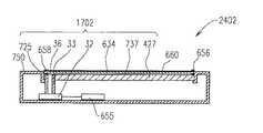
また、スピーカシステム1701が基板をさらに有し、基板とパネル634との間に空間を形成してもよい。このような基板427を有するスピーカシステム1702を備える電子機器2402を図24Aおよび図24Bに示す。
【0215】
図24Aは、電子機器2402の平面図であり、図24Bは図24Aに示す一点鎖線K2−L2に沿った電子機器2402の断面図である。基板427はパネル634に対向して配置され、基板427とパネル634との間に空間737が形成される。電子機器2402は基板427を支持する筐体750を備える。パネル634と基板427とはスペーサ725を用いて接続される。空間737は閉空間であることが望ましい。電子機器2402におけるパネル634から音が発生する動作およびパネル634のタッチパネルとしての動作は電子機器2401と同様である。
【0216】
本実施の形態では、パネル634は静電容量方式のタッチパネルと兼用したが、パネル634、筐体650および基板427に実施の形態10において説明したような電極を設け、パネル634を抵抗膜方式のタッチパネルと兼用しても同様の効果が得られる。また、パネル634を光学方式、電磁誘導方式、超音波方式等の他の方式のタッチパネルと兼用しても同様の効果が得られる。
【0217】
(実施の形態12)
本発明の実施の形態12における電子機器2600を図25および図26を参照して説明する。図25は、電子機器2600の斜視図であり、図26は図25に示す一点鎖線O−Pに沿った電子機器2600の断面図である。
【0218】
本実施の形態では、電子機器2600が携帯端末装置であるノート型パーソナルコンピュータであるとして説明するが、電子機器2600はノート型パーソナルコンピュータ等の携帯端末装置に限定されず、設置型の電子機器であってもよい。
【0219】
電子機器2600は、CPUおよびメモリ等(図示せず)を内蔵する筐体170と、スピーカシステム1900とを備える。
【0220】
スピーカシステム1900は、画像を表示する表示パネル421と、表示パネル421に表示された画像が透けて見えるように配置された透明パネル172と、振動板45(図26)を有し電気信号に応じて振動板45を振動させることにより音を放射する電気機械音響変換器422と、透明パネル172および表示パネル421を支持する筐体173とを備える。
【0221】
スピーカシステム1900において、表示パネル421と透明パネル172との間には空間189が形成されている。空間189は閉空間であることが望ましい。筐体173には音孔288が形成されている。筐体173は、電気機械音響変換器422から放射された音を空間189に伝達する音響伝達部材として機能する。透明パネル172は、音孔288を介して電気機械音響変換器422から空間189に伝達された音によって振動する。透明パネル172の面積は、振動板45の面積より大きい。表示パネル421は液晶ディスプレイであり得る。透明パネル172は、可視光を透過する材料であるPET、ガラス、アクリル等から形成される。電気機械音響変換器422は矩形形状である。
【0222】
電気機械音響変換器422は図2に示す電気機械音響変換器22の改変例であり、電気機械音響変換器422は筐体186を備える。本実施の形態において、振動板45は矩形形状である。図26には振動板45の短辺側が示される。筐体186は振動板45の上面および側面を覆って空室部187を形成する。筐体186にはスリット状の開口部188が形成されている。開口部188に筐体173の音孔288が接続される。
【0223】
スピーカシステム1900の動作は、電気機械音響変換器22を備える実施の形態1のスピーカシステム1000と同様である。電気機械音響変換器422の振動板45から放射された音は、空室部187、開口部188および音孔288を介して空間189に伝達される。透明パネル172は、空間189に伝達された音の圧力により駆動されて振動し、音を発生する。なお、スピーカシステム1900は電気機械音響変換器522をさらに備えてもよい。電気機械音響変換器522の構成要素は電気機械音響変換器422と同様である。この場合は、スピーカシステム1900の動作は、実施の形態4のスピーカシステム1400と同様であり、スピーカシステム1900はステレオ再生が可能となる。
【0224】
筐体186の開口部188は振動板45の振動方向と垂直な方向に形成されている。また、開口部188に接続される筐体173の音孔288の方向は、表示パネル421と平行である。これにより、電気機械音響変換器422は表示パネル421に隣接して同一平面上で配置することができ、薄型のスピーカシステム1900が実現できる。電気機械音響変換器422の振動板45から放射された音は、表示パネル421と平行に伝達される。スピーカシステム1900が電気機械音響変換器522を備える場合も同様に、電気機械音響変換器522は表示パネル421に隣接して同一平面上で配置することができるので、薄型のスピーカシステム1900が実現できる。
【0225】
また、表示パネル421に表示された画像が透けて見えるように透明パネル172を配置しているので、使用者から見た画像が表示される位置と音が放射される位置とが同じであるパーソナルコンピュータが実現できる。
【0226】
なお、本発明のスピーカシステムは表示パネルを有する電子機器であるテレビ、ゲーム機、カーナビゲーション等にも容易に適用可能である。また、本発明のスピーカシステムの電子機器への適用においては、透明パネルは音のみを放射する振動板として動作してもよいし、さらに透明パネルがタッチパネルを兼用してもよい。
【0227】
また、本発明の電気機械音響変換器が音響再生機能だけでなく上述したような機械振動機能を有する場合は、音響再生と機械振動の2つの機能が目的に応じて使い分けられる。
【0228】
【発明の効果】
本発明によれば、表示パネルに表示された画像が透けて見えるように透明パネルを配置し、透明パネルが振動可能なように構成されたスピーカシステムが提供される。これにより、使用者から見た画像が表示される位置と音が放射される位置とを同じにすることができる。
【0229】
また、本発明によれば、面積が小さい振動板から放射した音が空間に伝達され、空間に伝達された音により面積が大きい透明パネルが振動する。これにより、透明パネルの重量が大きくても、振動板を振動させるための小さな力で透明パネルを振動させることができ、十分な大きさの音を発生させることができる。
【0230】
また、本発明によれば、表示パネルと透明パネルとの間に基板が配置される。表示パネルを外部衝撃から保護する機能を基板が果たすことで、透明パネルを薄くすることができ、透明パネルの音響特性を向上させることができる。
【0231】
また、本発明によれば、電気機械音響変換器から放射された音を空間に伝達する音響伝達部材を音響管とすることにより、スピーカシステムの電子機器および携帯端末装置内での配置の自由度を大きくすることができる。また、電気機械音響変換器を表示パネルに隣接して設置する必要がなくなるので、表示パネルの設置スペースを拡大することができ、表示パネルを大型化することができる。
【0232】
また、本発明のスピーカシステムを携帯端末装置(例えば携帯電話機)に搭載するならば、透明パネルを受話音再生用レシーバの振動板として動作させることが可能となる。この場合、受話音は透明パネル全面から再生されているため、使用者の耳が面積の広い透明パネルのどの位置に接触しても受聴が可能である。このため、使用者の耳の位置を一点に一致させる必要がないので、使用者の耳が音の発生源からずれてしまうことはない。特に高齢者には受話音の聴き取りが容易な携帯電話機を実現できる。さらに、スピーカシステムに印加する電気入力を大きくすると、スピーカシステムは携帯端末装置の本体から離れても大きな音の受聴が可能な拡声スピーカとして動作する。この場合、テレビ電話のように画像を見ながらの会話が可能で、使用者から見た画像が表示される位置と音が放射される位置とが同じであるのでリアルな音響再生が可能となる。このため、音と映像の同時再生に最適な携帯端末装置が実現できる。
【0233】
さらに、本発明のスピーカシステムが複数の電気音響変換器を備えることで、ステレオ再生等のマルチチャネル再生が可能となる。
【0234】
また、本発明の電気機械音響変換器が音響再生機能に加えて機械振動機能を有する場合は、音響再生と機械振動の2機能を同時に実施可能なスピーカシステムが実現できる。
【0235】
また、タッチパネルを備える電子機器において、タッチパネルを本発明のスピーカシステムの透明パネルと兼用することで、本発明のスピーカシステムを簡単に構成できる電子機器を実現できる。
【図面の簡単な説明】
【図1A】本発明の実施の形態1におけるスピーカシステムを示す図
【図1B】本発明の実施の形態1におけるスピーカシステムを示す図
【図2】本発明の実施の形態1における電気機械音響変換器を示す図
【図3】本発明の実施の形態1におけるスピーカシステムの音圧−周波数特性を示す図
【図4】本発明の実施の形態2におけるスピーカシステムを示す図
【図5】本発明の実施の形態2におけるスピーカシステムを示す図
【図6】本発明の実施の形態2におけるスピーカシステムの音圧−周波数特性を示す図
【図7A】本発明の実施の形態3におけるスピーカシステムを示す図
【図7B】本発明の実施の形態3におけるスピーカシステムを示す図
【図8】本発明の実施の形態3における電気機械音響変換器を示す図
【図9A】本発明の実施の形態3におけるスピーカシステムを示す図
【図9B】本発明の実施の形態3におけるスピーカシステムを示す図
【図10A】本発明の実施の形態4におけるスピーカシステムを示す図
【図10B】本発明の実施の形態4におけるスピーカシステムを示す図
【図11】本発明の実施の形態4における電気機械音響変換器を示す図
【図12】本発明の実施の形態4におけるスピーカシステムを示す図
【図13】本発明の実施の形態5における携帯端末装置を示す図
【図14】本発明の実施の形態5における携帯端末装置を示す図
【図15】本発明の実施の形態6における携帯端末装置を示す図
【図16】本発明の実施の形態6における携帯端末装置を示す図
【図17】本発明の実施の形態7における携帯端末装置を示す図
【図18】本発明の実施の形態7における携帯端末装置を示す図
【図19A】本発明の実施の形態8における携帯端末装置を示す図
【図19B】本発明の実施の形態8における携帯端末装置を示す図
【図19C】本発明の実施の形態8における携帯端末装置を示す図
【図20】本発明の実施の形態8における電気機械音響変換器を示す図
【図21A】本発明の実施の形態9における電子機器を示す図
【図21B】本発明の実施の形態9における電子機器を示す図
【図22A】本発明の実施の形態10における電子機器を示す図
【図22B】本発明の実施の形態10における電子機器を示す図
【図23A】本発明の実施の形態11における電子機器を示す図
【図23B】本発明の実施の形態11における電子機器を示す図
【図24A】本発明の実施の形態11における電子機器を示す図
【図24B】本発明の実施の形態11における電子機器を示す図
【図25】本発明の実施の形態12における電子機器を示す図
【図26】本発明の実施の形態12におけるスピーカシステムを示す図
【図27】従来のスピーカシステムを示す図
【符号の説明】
20 筐体
21 表示パネル
22 電気機械音響変換器
23 音孔
24 透明パネル
25 弾性体
26 空間[0001]
BACKGROUND OF THE INVENTION
The present invention relates to a speaker system and a portable terminal device and an electronic apparatus that include the speaker system.
[0002]
[Prior art]
A conventional
[0003]
The
[0004]
Next, the operation of the
[0005]
[Problems to be solved by the invention]
In such a
[0006]
Moreover, in the conventional electronic device and portable terminal device, the display panel and the speaker are arranged at different positions. For this reason, the user feels uncomfortable because the position where the image is displayed and the position where the sound is emitted are different. For example, when an electronic device and a mobile terminal device are used as a videophone, the user feels uncomfortable that the voice of the other party is heard from a position different from the position of the image showing the other party. From the viewpoint of the user, it is natural and desirable that the position where the image is displayed and the position where the sound is emitted are the same.
[0007]
Therefore, an object of the present invention is to provide a speaker system in which the position where an image viewed from the user is displayed and the position where sound is emitted are the same.
[0008]
It is another object of the present invention to provide a speaker system having a high degree of freedom in arrangement in electronic devices and portable terminal devices.
[0009]
[Means for Solving the Problems]
The speaker system of the present invention radiates sound by vibrating a diaphragm according to an electric signal, a display panel that displays an image, a transparent panel that is arranged so that the image displayed on the display panel can be seen through. An electromechanical acoustic transducer, and an acoustic transmission member that transmits sound radiated from the electromechanical acoustic transducer to a space formed between the display panel and the transparent panel,A sound transmission member having a sound hole or an opening, and an end surface of the sound transmission member or the opening of the sound transmission member located opposite to the transparent panel is flush with a display surface of the display panel. Alternatively, it is arranged closer to the transparent panel side than the display surface of the display panel,The transparent panel is configured to be vibrated by sound transmitted from the electromechanical acoustic transducer to the space by the acoustic transmission member.It is characterized by,In this configurationThus, the above object is achieved.
[0010]
The sound transmission member is attached to the casing that supports the transparent panel.It is a formed sound holeMay be.
[0011]
Transparent panelBetween the lower surface of the periphery and the housing, the transparent panelYou may further provide the elastic body which supports a peripheral part.
[0012]
The acoustic transmission member may be an acoustic tube.
[0013]
The thickness of the peripheral part of the transparent panel may be thinner than the thickness of the central part of the transparent panel.
[0014]
The transparent panel is a filmThe peripheral part is fixed to the housing.May be.
[0015]
The electromechanical acoustic transducer may include a mechanical vibration unit that generates mechanical vibration.
[0016]
A plurality of electromechanical acoustic transducers and a plurality of acoustic transmission members are provided. Each of the plurality of electromechanical acoustic transducers has a diaphragm, and radiates sound by vibrating the diaphragm according to an electric signal. Each of the plurality of acoustic transmission members may transmit sound radiated from each of the plurality of electromechanical acoustic transducers to the space, and the plurality of acoustic transmission members may be coupled to different positions in the space, respectively. .
[0017]
A sound hole for transmitting sound is formed in the acoustic transmission member, and the direction of the sound hole may be parallel to the display panel.
[0018]
The electromechanical acoustic transducer further includes a casing surrounding the diaphragm, and the casing has an opening formed in a direction perpendicular to the vibration direction of the diaphragm, and the opening is connected to the acoustic transmission member. Also good.
[0019]
A portable terminal device of the present invention is a portable terminal device that includes a speaker system and a housing that supports the speaker system, and the speaker system includes a display panel that displays an image, and an image displayed on the display panel. Formed between a display panel and a transparent panel, a transparent panel arranged so that it can be seen through, an electromechanical acoustic transducer that has a diaphragm and emits sound by vibrating the diaphragm according to an electrical signal The sound radiated from the electromechanical acoustic transducer to the generated spaceA sound transmission member having a sound hole or an opening, and the sound hole or opening surface of the sound transmission member located opposite to the transparent panel is on the same plane as the display surface of the display panel or the display Arranged closer to the transparent panel side than the display surface of the panel,The transparent panel is configured to be vibrated by sound transmitted to the space from the electromechanical acoustic transducer by the acoustic transmission member, and the mobile terminal device is based on the antenna that receives the radio signal and the received radio signal. And an electric signal output unit for outputting the electric signal to the electromechanical acoustic transducer, wherein the electric signal indicates at least one of a received sound, a ringtone, music and voice.This configuration is characterized byThis achieves the above object.
[0020]
When the electrical signal indicates a received sound, the transparent panel may operate as a receiver.
[0021]
If the electrical signal indicates at least one of ringtone, music and voice, the transparent panel may operate as a loudspeaker.
[0022]
The electromechanical acoustic transducer has two diaphragms, a sound hole is formed in the housing, one diaphragm is provided to face the acoustic transmission member, and the other diaphragm is in the sound hole. You may provide so that it may oppose.
[0023]
An electronic device of the present invention is an electronic device including a speaker system and a housing that supports the speaker system, and the speaker system is configured to display a display panel that displays an image and an image displayed on the display panel. Formed between a display panel and a transparent panel, a transparent panel arranged to be visible, an electromechanical acoustic transducer having a diaphragm and emitting sound by vibrating the diaphragm in response to an electrical signal Transmits sound radiated from electromechanical acoustic transducer to spaceA sound transmission member having a sound hole or an opening, and an end face of the sound transmission member or the opening of the sound transmission member positioned opposite to the transparent panel is on the same plane as the substrate or of the display panel Place it closer to the transparent panel than the display surface,The transparent panel is configured to be vibrated by sound transmitted from the electromechanical acoustic transducer to the space by the acoustic transmission member,This configurationThis achieves the above object.
[0024]
The control unit further controls the operation of the electronic device, and the transparent panel also serves as a touch panel that detects contact of the contact means to the position of the transparent panel related to the operation menu icon displayed on the display panel. The electronic device may be operated in accordance with an operation menu icon related to the position of the transparent panel touched by the contact means.
[0025]
The touch panel may be one of a capacitive touch panel, an optical touch panel, an electromagnetic induction touch panel, and an ultrasonic touch panel.
[0026]
The speaker system of the present invention has a display panel for displaying an image, a transparent panel arranged so that the image displayed on the display panel can be seen through, and an image seen through between the display panel and the transparent panel. An electromechanical acoustic transducer that has a substrate disposed on the substrate and a diaphragm, and radiates sound by vibrating the diaphragm in response to an electrical signal, and a space formed between the transparent panel and the substrate. Transmits sound radiated from a mechanical acoustic transducerAn acoustic transmission member having a sound hole or an opening, and an end surface of the sound hole or the opening of the acoustic transmission member located opposite to the transparent panel is arranged on the same plane as the substrate,The transparent panel is configured to be vibrated by sound transmitted from the electromechanical acoustic transducer to the space by the acoustic transmission member.This configuration is characterized byThis achieves the above object.
[0027]
SaidThe acoustic transmission member is formed on the substrate.Sound holeIt is good.
[0028]
The space may be formed between the spacer that connects the peripheral portion of the transparent panel and the peripheral portion of the substrate, the transparent panel, and the substrate.
[0029]
The transparent panel is a filmThe peripheral part is fixed to the housing.May be.
[0030]
The acoustic transmission member may be an acoustic tube.
[0031]
A plurality of electromechanical acoustic transducers and a plurality of acoustic transmission members are provided. Each of the plurality of electromechanical acoustic transducers has a diaphragm, and radiates sound by vibrating the diaphragm according to an electric signal. Each of the plurality of acoustic transmission members may transmit sound radiated from each of the plurality of electromechanical acoustic transducers to the space, and the plurality of acoustic transmission members may be coupled to different positions in the space, respectively. .
[0032]
A portable terminal device of the present invention is a portable terminal device that includes a speaker system and a housing that supports the speaker system, and the speaker system includes a display panel that displays an image, and an image displayed on the display panel. A transparent panel arranged to show through, a substrate arranged so that an image can be seen through between the display panel and the transparent panel, and a diaphragm, and the diaphragm is vibrated according to an electric signal. Transmits sound emitted from the electromechanical acoustic transducer to the space formed between the transparent panel and the substrate, and the electromechanical acoustic transducer that emits sound byAn acoustic transmission member having a sound hole or an opening, and an end surface of the sound hole or the opening of the acoustic transmission member located opposite to the transparent panel is arranged on the same plane as the substrate,The transparent panel is configured to be vibrated by sound transmitted to the space from the electromechanical acoustic transducer by the acoustic transmission member, and the mobile terminal device is based on the antenna that receives the radio signal and the received radio signal. And an electric signal output unit for outputting the electric signal to the electromechanical acoustic transducer, wherein the electric signal indicates at least one of a received sound, a ringtone, music and voice.This configuration is characterized byThis achieves the above object.
[0033]
When the electrical signal indicates a received sound, the transparent panel may operate as a receiver.
[0034]
If the electrical signal indicates at least one of ringtone, music and voice, the transparent panel may operate as a loudspeaker.
[0035]
The electromechanical acoustic transducer has two diaphragms, a sound hole is formed in the housing, one diaphragm is provided to face the acoustic transmission member, and the other diaphragm is in the sound hole. You may provide so that it may oppose.
[0036]
An electronic device of the present invention is an electronic device including a speaker system and a housing that supports the speaker system, and the speaker system is configured to display a display panel that displays an image and an image displayed on the display panel. A transparent panel arranged so that it can be seen, a board arranged so that an image can be seen through between the display panel and the transparent panel, and a diaphragm that vibrates in response to an electrical signal. The sound radiated from the electromechanical acoustic transducer is transmitted to the space formed between the transparent panel and the substrate.An acoustic transmission member having a sound hole or an opening, and an end surface of the sound hole or the opening of the acoustic transmission member located opposite to the transparent panel is arranged on the same plane as the substrate,The transparent panel is configured to be vibrated by sound transmitted from the electromechanical acoustic transducer to the space by the acoustic transmission member.This configuration is characterized byThis achieves the above object.
[0037]
The control unit further controls the operation of the electronic device, and the transparent panel also serves as a touch panel that detects contact of the contact means to the position of the transparent panel related to the operation menu icon displayed on the display panel. The electronic device may be operated in accordance with an operation menu icon related to the position of the transparent panel touched by the contact means.
[0038]
You may further provide the 1st transparent electrode which has the electrical resistance provided in the surface facing the board | substrate of a transparent panel, and the 2nd transparent electrode which has the electrical resistance provided in the surface facing the transparent panel of a board | substrate.
[0039]
An electronic apparatus of the present invention includes a speaker system,SaidAn electronic device comprising a housing for supporting a speaker system,SaidThe speaker systemA display panel for displaying an image, a transparent panel arranged so that the image displayed on the display panel can be seen through,An electromechanical acoustic transducer that has a diaphragm and radiates sound by vibrating the diaphragm in response to an electrical signal;SaidPanel andSaidIn the space formed between the housingSaidTransmits sound emitted from electromechanical acoustic transducersA sound transmission member having a sound hole or an opening, and an end face of the sound transmission member or the opening of the sound transmission member positioned opposite to the transparent panel is on the same plane as the substrate or of the display panel Arranged closer to the transparent panel than the display surface, the transparentPanel isSaidFrom the electromechanical acoustic transducer by an acoustic transmission memberSaidIt is configured to be able to vibrate by sound transmitted to space,The electronic device isA control unit for controlling the operation of the electronic device;TransparentPanel isThe displayIt also serves as a touch panel that detects the contact of the contact means to the position indicated by the panel operation menu,SaidThe control unitSaidThe contact means is shown in the contacted positionSaidDepending on the operation menuSaidAn electronic device may be operated.
[0040]
An electronic device of the present invention is an electronic device including a speaker system and a housing that supports the speaker system, and the speaker system includes:A display panel for displaying an image, a transparent panel arranged so that the image displayed on the display panel can be seen through,A space formed between the substrate disposed opposite to the panel, an electromechanical acoustic transducer that has a diaphragm and emits sound by vibrating the diaphragm in response to an electrical signal, and the panel and the substrate Transmits sound radiated from electromechanical acoustic transducer toAn acoustic transmission member having a sound hole or an opening, and an end surface of the sound hole or the opening of the acoustic transmission member located opposite to the transparent panel is disposed on the same plane as the substrate, TransparentThe panel is configured to be vibrated by sound transmitted from the electromechanical acoustic transducer to the space by the acoustic transmission member, and further includes a control unit that controls the operation of the electronic device,TransparentPanel isThe displayThe control unit may also operate the electronic device in accordance with the operation menu indicated at the position where the contact means is in contact with the touch panel that detects contact of the contact means with the position indicated on the panel operation menu.
[0041]
In the speaker system of the present invention, the electrical signal indicates at least one of a received sound, a ring tone, and audio information of a plurality of channels, and when the electrical signal indicates at least one of the received sound and the ring tone, a plurality of When an electric signal is input to the electromechanical acoustic transducer and the electric signal indicates audio information of a plurality of channels, an electric signal indicating audio information of a different channel is input to the plurality of electromechanical acoustic transducers. Good.
[0042]
In the mobile terminal device of the present invention, the speaker system includes a plurality of electromechanical acoustic transducers and a plurality of acoustic transmission members, and each of the plurality of electromechanical acoustic transducers includes a diaphragm, In response, the diaphragm is vibrated to emit sound, each of the plurality of acoustic transmission members transmits sound radiated from each of the plurality of electromechanical acoustic transducers to the space, and the plurality of acoustic transmission members are When coupled to different positions in the space and the electrical signal indicates at least one of the incoming and incoming sounds, the electrical signal is input to a plurality of electromechanical acoustic transducers and the electrical signal is a multi-channel audio. In the case of indicating information, an electric signal indicating audio information of a different channel may be input to each of the plurality of electromechanical acoustic transducers.
In the speaker system of the present invention, the acoustic transmission member is a sound hole formed in a casing that supports the transparent panel, and the casing has a first recess and a first recess provided at a position where the transparent panel is attached. A second recess provided at the bottom of the first recess, the sound hole being provided at the bottom of the first recess, and a display surface of the display panel when the display panel is attached to the second recess. You may comprise so that the bottom part of a said 1st recessed part may be located on the same plane.
In the mobile terminal device of the present invention, the acoustic transmission member is a sound hole formed in a casing that supports the transparent panel, and the casing includes a first recess provided at a position where the transparent panel is attached. A second concave portion provided in the first bottom portion, the sound hole being provided in the bottom portion of the first concave portion, and the display surface of the display panel when the display panel is attached to the second concave portion And the bottom of the first concave portion may be located on the same plane.
In the electronic device according to the aspect of the invention, the acoustic transmission member may be a sound hole formed in a casing that supports the transparent panel, and the casing may include a first recess provided at a position where the transparent panel is attached and a first recess. A second recess provided at the bottom of the first recess, the sound hole being provided at the bottom of the first recess, and a display surface of the display panel when the display panel is attached to the second recess. You may comprise so that the bottom part of a said 1st recessed part may be located on the same plane.
[0043]
DETAILED DESCRIPTION OF THE INVENTION
Hereinafter, embodiments of the present invention will be described with reference to the drawings.
[0044]
(Embodiment 1)
A
[0045]
The
[0046]
In the
[0047]
FIG. 2 is a cross-sectional view of the electromechanical
[0048]
The electromechanical
[0049]
Next, the operation of the
[0050]
When an electrical signal is applied to the
[0051]
FIG. 3 shows the measurement result of the sound pressure-frequency characteristics of the
[0052]
A characteristic I shown in FIG. 3 indicates a characteristic of sound radiated from the electromechanical
[0053]
However, this decrease in sound pressure level can be improved by adjusting the acoustic volume of the
[0054]
Further, an acrylic material having a thickness of 20 μm and a weight of about 6 mg was used as the
[0055]
The weight of the transparent panel 24 (a transparent acrylic material having a length of 60 mm, a width of 35 mm, and a thickness of 1.7 mm) was about 4200 mg. The ratio of the weight of the
[0056]
On the other hand, in the
[0057]
In the above example, the effective vibration area S of the diaphragm 45.1= 98.5 mm, vibration area S of
[0058]
As described above, the electromechanical
[0059]
Further, since the
[0060]
Further, by supporting the
[0061]
In the first embodiment, the
[0062]
In the first embodiment, an electrodynamic speaker is used as the electromechanical
[0063]
(Embodiment 2)
A
[0064]
The
[0065]
In the
[0066]
The components of the electromechanical
[0067]
Next, the operation of the
[0068]
When an electrical signal is applied to the
[0069]
FIG. 6 shows the measurement result of the sound pressure-frequency characteristic of the
[0070]
A characteristic III shown in FIG. 6 indicates a characteristic of sound radiated from the electromechanical
[0071]
Further, an acrylic material having a thickness of 20 μm and a weight of about 6 mg was used as the
[0072]
The weight of the transparent panel 224 (a transparent PET material having a length of 90 mm, a width of 60 mm, and a thickness of 0.1 mm) was about 700 mg. The ratio of the weight of the
[0073]
On the other hand, in the
[0074]
In the above example, the effective vibration area S of the diaphragm 45.1= 98.5 mm, vibration area S of
[0075]
As described above, the electromechanical
[0076]
Further, since the
[0077]
In the
[0078]
Further, in the manufacturing process of the
[0079]
The
[0080]
In the second embodiment, an electrodynamic speaker is used as the electromechanical
[0081]
(Embodiment 3)
A
[0082]
The
[0083]
In the
[0084]
FIG. 8 is a cross-sectional view of the electromechanical
[0085]
The electromechanical
And a
[0086]
Next, the operation of the
[0087]
When an electric signal is applied to the
[0088]
As a difference from the
[0089]
The
[0090]
Further, the entire surface of the
[0091]
In this embodiment, a piezoelectric speaker is used as the electromechanical
[0092]
Next, a
[0093]
The
[0094]
Next, the operation of the
[0095]
Referring to FIGS. 8, 9A and 9B, when an electric signal is applied to input
[0096]
In the
[0097]
Although a piezoelectric speaker is used as the electromechanical
[0098]
(Embodiment 4)
A
[0099]
The
[0100]
A
[0101]
Next, the operation of the
[0102]
As a difference from the
[0103]
The components of the electromechanical
[0104]
For example, when an electrical signal indicating right channel audio information is input to the electromechanical
[0105]
If the
[0106]
The
[0107]
Furthermore, you may form an opening part in the up-down and left-right direction of the
[0108]
When the electrical signal is a monaural signal, the same electrical signal may be input to a plurality of electromechanical acoustic transducers, or the electrical signal may be input to only one electromechanical acoustic transducer.
[0109]
Further, instead of the electromechanical
[0110]
The operation of radiating sound from
[0111]
An operation in which the
[0112]
Thus, the electromechanical
[0113]
In addition, when a game or the like is performed using an electronic device in which the
[0114]
Further, as described above, even when the electrical signal is a monaural signal, not only the sound reproduction from the
[0115]
Further, instead of the electromechanical
[0116]
Next, a
[0117]
In addition to the components of the
[0118]
Next, the operation of the
[0119]
The operations of the electromechanical
[0120]
For example, when an electrical signal indicating right channel audio information is input to the electromechanical
[0121]
Further, by connecting the
[0122]
Both electromechanical
[0123]
Further, instead of the electromechanical
[0124]
An acoustic tube may be provided between the electromechanical
[0125]
The
[0126]
As the electromechanical
[0127]
In
[0128]
(Embodiment 5)
A
[0129]
Although the
[0130]
The
[0131]
Next, the operation of the
[0132]
The operation of the
[0133]
When an electrical signal indicating a received sound is applied to the electromechanical acoustic transducer 32 (FIG. 14), the received sound is reproduced from the
[0134]
In addition, if an electric signal indicating a ring tone, music, voice or game sound effect for notifying the incoming call is applied to the electromechanical
[0135]
If the
[0136]
Similar to the description in the first embodiment, the
[0137]
In addition, when the
[0138]
Next, the operation of the
[0139]
The
[0140]
The
[0141]
First, when the
[0142]
In this case, the user increases the reproduction volume by increasing the amplification factor of the electric
[0143]
Also, applications for simultaneous playback of images and sounds include playback of music promotion videos and use as game machines.
[0144]
Note that the
[0145]
(Embodiment 6)
A
[0146]
Although the
[0147]
The
[0148]
Next, the operation of the
[0149]
When an electric signal indicating the received sound is applied to the electromechanical acoustic transducer 32 (FIG. 16), the received sound is reproduced from the
[0150]
In addition, if an electric signal indicating a ring tone, music, voice, or a game sound effect for notifying an incoming call is applied to the electromechanical
[0151]
If the
[0152]
As illustrated in FIG. 16, the
[0153]
Note that the
[0154]
In the present embodiment, the portable terminal device equipped with the speaker system of the invention is disclosed. However, the speaker system of the present invention is an electronic device having a display panel, such as a television system, a personal computer, a game machine, or a car navigation system. Can be used as
[0155]
(Embodiment 7)
A
[0156]
Although the
[0157]
A
[0158]
Next, the operation of the
[0159]
The operation of the
[0160]
When an electric signal indicating the received sound is applied to at least one of the electromechanical
[0161]
Further, if an electric signal indicating an incoming sound, music, voice, or sound effect of a game is applied to at least one of the electromechanical
[0162]
Further, if the same electrical signal is applied to the electromechanical
[0163]
Further, if the
[0164]
Similar to the description in
[0165]
Next, the operation of the
[0166]
The
[0167]
The
[0168]
First, when the
[0169]
In this case, the user increases the reproduction volume by increasing the amplification factor of the electric
[0170]
When the
[0171]
Also, applications for simultaneous playback of images and sounds include playback of music promotion videos and use as game machines.
[0172]
In the
[0173]
Note that the
[0174]
In the present embodiment, the portable terminal device equipped with the speaker system of the invention is disclosed. However, the speaker system of the present invention is an electronic device having a display panel, such as a television system, a personal computer, a game machine, or a car navigation system. Can be used as
[0175]
(Embodiment 8)
A
[0176]
Although the
[0177]
The
[0178]
The electromechanical
[0179]
Next, the operation of the electromechanical
[0180]
When an electrical signal is applied to the
[0181]
Sound radiated from the
[0182]
In the electromechanical
[0183]
The
[0184]
Note that the
[0185]
(Embodiment 9)
[0186]
In this embodiment, the
[0187]
[0188]
A
[0189]
Next, the operation of the
[0190]
The user presses and presses the position of the
[0191]
A general touch panel operation is disclosed in, for example, Japanese Patent Laid-Open No. 9-265341. In the present invention, the
[0192]
Thus, by combining the touch panel and the transparent panel for sound reproduction, an electronic device that reproduces sound from the touch panel is realized, and the components for sound reproduction can be simplified. The speaker system can be easily realized. Since the touch panel is transparent and transmits visible light, the image displayed on the display panel is not blocked.
[0193]
In this embodiment, the
[0194]
Further, the
[0195]
(Embodiment 10)
[0196]
In this embodiment, the
[0197]
[0198]
A
[0199]
Next, the operation of the
[0200]
The
[0201]
In this embodiment, the
[0202]
Thus, by combining the touch panel and the transparent panel for sound reproduction, an electronic device that reproduces sound from the touch panel can be realized, and the components for sound reproduction can be simplified. Realization is easy. Since the touch panel is transparent and transmits visible light, the image displayed on the display panel is not blocked.
[0203]
The
[0204]
Further, the
[0205]
In this embodiment, the
[0206]
Further, the
[0207]
(Embodiment 11)
In the
[0208]
[0209]
The
[0210]
The
[0211]
An
[0212]
The user presses and presses the position of the
[0213]
In the present embodiment,
[0214]
The
[0215]
24A is a plan view of the
[0216]
In this embodiment mode, the
[0217]
(Embodiment 12)
[0218]
In this embodiment, description is made assuming that
[0219]
[0220]
The
[0221]
In the
[0222]
The electromechanical
[0223]
The operation of the
[0224]
The
[0225]
In addition, since the
[0226]
Note that the speaker system of the present invention can be easily applied to televisions, game machines, car navigations, and the like, which are electronic devices having a display panel. Moreover, in the application of the speaker system of the present invention to an electronic device, the transparent panel may operate as a diaphragm that emits only sound, or the transparent panel may also serve as a touch panel.
[0227]
Further, when the electromechanical acoustic transducer of the present invention has not only the sound reproduction function but also the mechanical vibration function as described above, the two functions of sound reproduction and mechanical vibration are properly used according to the purpose.
[0228]
【The invention's effect】
ADVANTAGE OF THE INVENTION According to this invention, the speaker system comprised so that a transparent panel can be arrange | positioned so that the image displayed on the display panel can be seen through, and a transparent panel can vibrate is provided. Thereby, the position where the image seen from the user is displayed and the position where the sound is emitted can be made the same.
[0229]
Further, according to the present invention, the sound radiated from the diaphragm having a small area is transmitted to the space, and the transparent panel having the large area is vibrated by the sound transmitted to the space. Thereby, even if the weight of the transparent panel is large, the transparent panel can be vibrated with a small force for vibrating the diaphragm, and a sufficiently large sound can be generated.
[0230]
Moreover, according to this invention, a board | substrate is arrange | positioned between a display panel and a transparent panel. Since the substrate functions to protect the display panel from external impact, the transparent panel can be thinned, and the acoustic characteristics of the transparent panel can be improved.
[0231]
In addition, according to the present invention, the acoustic transmission member that transmits the sound radiated from the electromechanical acoustic transducer to the space is an acoustic tube, so that the degree of freedom of arrangement of the speaker system in the electronic device and the portable terminal device is increased. Can be increased. Further, since it is not necessary to install the electromechanical acoustic transducer adjacent to the display panel, the installation space for the display panel can be expanded, and the display panel can be enlarged.
[0232]
Further, if the speaker system of the present invention is mounted on a mobile terminal device (for example, a mobile phone), the transparent panel can be operated as a diaphragm for a receiver for reproducing received sound. In this case, since the received sound is reproduced from the entire surface of the transparent panel, it can be heard regardless of the position of the user's ear touching the transparent panel having a large area. For this reason, it is not necessary to match the position of the user's ear to a single point, so that the user's ear is not displaced from the sound source. In particular, it is possible to realize a mobile phone in which elderly people can easily listen to the received sound. Furthermore, when the electric input applied to the speaker system is increased, the speaker system operates as a loudspeaker capable of listening to a loud sound even when it is separated from the main body of the mobile terminal device. In this case, it is possible to have a conversation while looking at the image like a videophone, and since the position where the image viewed from the user is displayed and the position where the sound is emitted are the same, realistic sound reproduction is possible. . For this reason, the portable terminal device optimal for simultaneous reproduction of sound and video can be realized.
[0233]
Furthermore, since the speaker system of the present invention includes a plurality of electroacoustic transducers, multi-channel reproduction such as stereo reproduction becomes possible.
[0234]
In addition, when the electromechanical acoustic transducer of the present invention has a mechanical vibration function in addition to a sound reproduction function, a speaker system capable of simultaneously performing two functions of sound reproduction and mechanical vibration can be realized.
[0235]
Moreover, in an electronic device including a touch panel, an electronic device that can easily configure the speaker system of the present invention can be realized by using the touch panel also as a transparent panel of the speaker system of the present invention.
[Brief description of the drawings]
FIG. 1A is a diagram showing a speaker system according to
FIG. 1B is a diagram showing a speaker system according to
FIG. 2 is a diagram showing an electromechanical acoustic transducer according to
FIG. 3 is a diagram showing sound pressure-frequency characteristics of the speaker system according to
FIG. 4 shows a speaker system according to
FIG. 5 is a diagram showing a speaker system according to
FIG. 6 is a diagram showing sound pressure-frequency characteristics of the speaker system according to
FIG. 7A is a diagram showing a speaker system according to Embodiment 3 of the present invention.
FIG. 7B is a diagram showing a speaker system according to Embodiment 3 of the present invention.
FIG. 8 is a diagram showing an electromechanical acoustic transducer according to a third embodiment of the present invention.
FIG. 9A shows a speaker system according to Embodiment 3 of the present invention.
FIG. 9B is a diagram showing a speaker system according to Embodiment 3 of the present invention.
FIG. 10A is a diagram showing a speaker system according to Embodiment 4 of the present invention.
FIG. 10B is a diagram showing a speaker system according to Embodiment 4 of the present invention.
FIG. 11 is a diagram showing an electromechanical acoustic transducer according to a fourth embodiment of the present invention.
FIG. 12 is a diagram showing a speaker system according to Embodiment 4 of the present invention.
FIG. 13 is a diagram showing a portable terminal device according to a fifth embodiment of the present invention.
FIG. 14 is a diagram showing a mobile terminal device according to a fifth embodiment of the present invention.
FIG. 15 is a diagram showing a mobile terminal device according to a sixth embodiment of the present invention.
FIG. 16 is a diagram showing a mobile terminal device according to a sixth embodiment of the present invention.
FIG. 17 shows a mobile terminal device according to a seventh embodiment of the present invention.
FIG. 18 is a diagram showing a mobile terminal device according to a seventh embodiment of the present invention.
FIG. 19A is a diagram showing a mobile terminal device according to Embodiment 8 of the present invention;
FIG. 19B is a diagram showing a mobile terminal device according to Embodiment 8 of the present invention;
FIG. 19C is a diagram showing a mobile terminal device according to Embodiment 8 of the present invention;
FIG. 20 is a diagram showing an electromechanical acoustic transducer according to an eighth embodiment of the present invention.
FIG. 21A shows an electronic device according to a ninth embodiment of the present invention.
FIG. 21B shows an electronic device according to Embodiment 9 of the present invention.
22A is a diagram showing an electronic device in
22B is a diagram showing an electronic device in
FIG. 23A is a diagram showing an electronic device in
FIG. 23B shows an electronic device according to
FIG. 24A is a diagram showing an electronic device according to
FIG. 24B is a diagram showing an electronic device in
FIG 25 illustrates an electronic device according to a twelfth embodiment of the present invention.
FIG. 26 is a diagram showing a speaker system according to a twelfth embodiment of the present invention.
FIG. 27 shows a conventional speaker system.
[Explanation of symbols]
20 housing
21 Display panel
22 Electromechanical acoustic transducer
23 sound hole
24 Transparent panel
25 Elastic body
26 space
Claims (38)
Translated fromJapanese前記表示パネルに表示された前記画像が透けて見えるように配置された透明パネルと、
振動板を有し、電気信号に応じて前記振動板を振動させることにより音を放射する電気機械音響変換器と、
前記表示パネルと前記透明パネルとの間に形成された空間に前記電気機械音響変換器から放射された音を伝達する音孔或は開口部を有する音響伝達部材とを備え、
前記透明パネルと対向して位置する前記音響伝達部材の前記音孔或は前記開口部の端面を前記表示パネルの表示面と同一平面上或いは前記表示パネルの表示面よりも前記透明パネル側に近づけて配置し、
前記透明パネルは、前記音響伝達部材により前記電気機械音響変換器から前記空間に伝達された音によって振動可能なように構成されていることを特徴とするスピーカシステム。A display panel for displaying images,
A transparent panel arranged so that the image displayed on the display panel can be seen through;
An electromechanical acoustic transducer that has a diaphragm and emits sound by vibrating the diaphragm in response to an electrical signal;
An acoustic transmission member having asound hole or an opening for transmitting sound radiated from the electromechanical acoustic transducer in a space formed between the display panel and the transparent panel;
An end surface of the sound hole or the opening of the acoustic transmission member positioned facing the transparent panel is on the same plane as the display surface of the display panel or closer to the transparent panel side than the display surface of the display panel. And place
The speaker systemis configured so that the transparent panel can be vibrated by sound transmitted from the electromechanical acoustic transducer to the space by the acoustic transmission member.
前記フィルムの周辺部は、前記筐体に固着された構成であることを特徴とする請求項1に記載のスピーカシステム。The transparent panel is a film;
The speaker system accordingto claim 1, wherein a peripheral portion of the film is fixed to the housing .
複数の電気機械音響変換器と、
複数の音響伝達部材とを備え、
前記複数の電気機械音響変換器のそれぞれは、振動板を有し、電気信号に応じて前記振動板を振動させることにより音を放射し、
前記複数の音響伝達部材のそれぞれは、前記複数の電気機械音響変換器のそれぞれから放射される音を前記空間に伝達し、
前記複数の音響伝達部材は、それぞれ前記空間の異なる位置に結合されていることを特徴とする請求項1に記載のスピーカシステム。The speaker system includes:
A plurality of electromechanical acoustic transducers;
A plurality of acoustic transmission members,
Each of the plurality of electromechanical acoustic transducers has a diaphragm, and radiates sound by vibrating the diaphragm according to an electric signal,
Each of the plurality of acoustic transmission members transmits sound radiated from each of the plurality of electromechanical acoustic transducers to the space,
The speaker system accordingto claim 1, wherein the plurality of acoustic transmission members are respectively coupled to different positions in the space.
前記音孔の方向は、前記表示パネルと平行であることを特徴とする請求項1に記載のスピーカシステム。A sound hole for transmitting the sound is formed in the acoustic transmission member,
The speaker system accordingto claim 1, wherein a direction of the sound hole is parallel to the display panel.
前記筐体には、前記振動板の振動方向と垂直な方向に開口部が形成されており、
前記開口部は前記音響伝達部材と接続されることを特徴とする請求項1に記載のスピーカシステム。The electromechanical acoustic transducer further includes a housing surrounding the diaphragm,
The housing has an opening formed in a direction perpendicular to the vibration direction of the diaphragm,
The speaker system accordingto claim 1, wherein the opening is connected to the acoustic transmission member.
前記スピーカシステムは、画像を表示する表示パネルと、
前記表示パネルに表示された前記画像が透けて見えるように配置された透明パネルと、
振動板を有し、電気信号に応じて前記振動板を振動させることにより音を放射する電気機械音響変換器と、
前記表示パネルと前記透明パネルとの間に形成された空間に前記電気機械音響変換器から放射された音を伝達する音孔或は開口部を有する音響伝達部材とを備え、
前記透明パネルと対向して位置する前記音響伝達部材の前記音孔或は開口面を前記表示パネルの表示面と同一平面上或いは前記表示パネルの表示面よりも前記透明パネル側に近づけて配置し、
前記透明パネルは、前記音響伝達部材により前記電気機械音響変換器から前記空間に伝達された音によって振動可能なように構成されており、
前記携帯端末装置は、無線信号を受信するアンテナと、前記受信した無線信号に基づいて電気信号を前記電気機械音響変換器へ出力する信号出力部とをさらに備え、
前記電気信号は、受話音、着信音、音楽および音声の内の少なくとも1つを示すことを特徴とする携帯端末装置。A portable terminal device comprising a speaker system and a housing that supports the speaker system,
The speaker system includes a display panel that displays an image;
A transparent panel arranged so that the image displayed on the display panel can be seen through;
An electromechanical acoustic transducer that has a diaphragm and emits sound by vibrating the diaphragm in response to an electrical signal;
An acoustic transmission member having asound hole or an opening for transmitting sound radiated from the electromechanical acoustic transducer in a space formed between the display panel and the transparent panel;
The sound hole or opening surface of the acoustic transmission member located opposite to the transparent panel is arranged on the same plane as the display surface of the display panel or closer to the transparent panel side than the display surface of the display panel. ,
The transparent panel is configured to be vibrated by sound transmitted from the electromechanical acoustic transducer to the space by the acoustic transmission member,
The portable terminal device further includes an antenna that receives a radio signal, and a signal output unit that outputs an electric signal to the electromechanical acoustic transducer based on the received radio signal,
The electrical signal is reception sound, ringtones, mobile terminaland wherein the indicating at least one of music and speech.
前記筐体には音孔が形成され、
一方の前記振動板は、前記音響伝達部材に対向するように設けられ、
他方の前記振動板は、前記音孔に対向するように設けられることを特徴とする請求項11に記載の携帯端末装置。The electromechanical acoustic transducer has two of the diaphragms,
A sound hole is formed in the housing,
One of the diaphragms is provided to face the acoustic transmission member,
The mobile terminal device accordingto claim 11, wherein the other diaphragm is provided to face the sound hole.
前記スピーカシステムは、画像を表示する表示パネルと、
前記表示パネルに表示された前記画像が透けて見えるように配置された透明パネルと、
振動板を有し電気信号に応じて前記振動板を振動させることにより音を放射する電気機械音響変換器と、
前記表示パネルと前記透明パネルとの間に形成された空間に前記電気機械音響変換器から放射された音を伝達する音孔或は開口部を有する音響伝達部材とを備え、
前記透明パネルと対向して位置する前記音響伝達部材の前記音孔或は開口部の端面を前記基板と同一平面上或いは前記表示パネルの表示面よりも前記透明パネル側に近づけて配置し、
前記透明パネルは、前記音響伝達部材により前記電気機械音響変換器から前記空間に伝達された音によって振動可能なように構成されていることを特徴とする電子機器。An electronic device comprising a speaker system and a casing that supports the speaker system,
The speaker system includes a display panel that displays an image;
A transparent panel arranged so that the image displayed on the display panel can be seen through;
An electromechanical acoustic transducer that has a diaphragm and emits sound by vibrating the diaphragm in response to an electrical signal;
An acoustic transmission member having asound hole or an opening for transmitting sound radiated from the electromechanical acoustic transducer in a space formed between the display panel and the transparent panel;
An end face of the sound hole or opening of the acoustic transmission member positioned facing the transparent panel is arranged on the same plane as the substrate or closer to the transparent panel side than the display surface of the display panel,
The said transparent panel is comprised so that it can vibrate with the sound transmitted to the said space from the said electromechanical acoustic transducer by the said acoustic transmission member, The electronic devicecharacterized by the above-mentioned .
前記透明パネルは、前記表示パネルに表示された操作メニューアイコンに関連する前記透明パネルの位置への接触手段の接触を検出するタッチパネルを兼用し、
前記制御部は、前記接触手段が接触した前記透明パネルの位置に関連する前記操作メニューアイコンに応じて前記電子機器を動作させることを特徴とする請求項15に記載の電子機器。The electronic device further includes a control unit that controls the operation of the electronic device,
The transparent panel also serves as a touch panel that detects contact of the contact means to the position of the transparent panel related to the operation menu icon displayed on the display panel,
The electronic device accordingto claim 15, wherein the control unit operates the electronic device in accordance with the operation menu icon related to a position of the transparent panel with which the contact unit is in contact.
前記表示パネルに表示された前記画像が透けて見えるように配置された透明パネルと、
前記表示パネルと前記透明パネルとの間に前記画像が透けて見えるように配置された基板と、
振動板を有し電気信号に応じて前記振動板を振動させることにより音を放射する電気機械音響変換器と、
前記透明パネルと前記基板との間に形成された空間に前記電気機械音響変換器から放射された音を伝達する音孔或は開口部を有する音響伝達部材とを備え、
前記透明パネルと対向して位置する前記音響伝達部材の前記音孔或は開口部の端面を前記基板と同一平面上に配置し、
前記透明パネルは、前記音響伝達部材により前記電気機械音響変換器から前記空間に伝達された音によって振動可能なように構成されていることを特徴とするスピーカシステム。A display panel for displaying images,
A transparent panel arranged so that the image displayed on the display panel can be seen through;
A substrate disposed so that the image can be seen through between the display panel and the transparent panel;
An electromechanical acoustic transducer that has a diaphragm and emits sound by vibrating the diaphragm in response to an electrical signal;
An acoustic transmission member having asound hole or an opening for transmitting sound radiated from the electromechanical acoustic transducer to a space formed between the transparent panel and the substrate;
An end face of the sound hole or opening of the acoustic transmission member located facing the transparent panel is disposed on the same plane as the substrate ,
The transparent panel speakersystem characterized by being configured to be vibrated by sounds transmitted to the space from the electromechanical acoustic transducer by the acoustic transfer member.
前記フィルムの周辺部は、前記筐体に固着された構成であることを特徴とする請求項18に記載のスピーカシステム。The transparent panel isRi filmDer,
The speaker system accordingto claim 18, wherein a peripheral portion of the film is fixed to the housing .
複数の音響伝達部材とを備え、
前記複数の電気機械音響変換器のそれぞれは、振動板を有し、電気信号に応じて前記振動板を振動させることにより音を放射し、
前記複数の音響伝達部材のそれぞれは、前記複数の電気機械音響変換器のそれぞれから放射される音を前記空間に伝達し、
前記複数の音響伝達部材は、それぞれ空間の異なる位置に結合されていることを特徴とする請求項18に記載のスピーカシステム。A plurality of electromechanical acoustic transducers;
A plurality of acoustic transmission members,
Each of the plurality of electromechanical acoustic transducers has a diaphragm, and radiates sound by vibrating the diaphragm according to an electric signal,
Each of the plurality of acoustic transmission members transmits sound radiated from each of the plurality of electromechanical acoustic transducers to the space,
The speaker system accordingto claim 18, wherein the plurality of sound transmission members are respectively coupled to different positions in the space.
前記スピーカシステムは、画像を表示する表示パネルと、前記表示パネルに表示された前記画像が透けて見えるように配置された透明パネルと、前記表示パネルと前記透明パネルとの間に前記画像が透けて見えるように配置された基板と、振動板を有し電気信号に応じて前記振動板を振動させることにより音を放射する電気機械音響変換器と、前記透明パネルと前記基板との間に形成された空間に前記電気機械音響変換器から放射された音を伝達する音孔或は開口部を有する音響伝達部材とを備え、前記透明パネルと対向して位置する前記音響伝達部材の前記音孔或は開口部の端面を前記基板と同一平面上に配置し、前記透明パネルは、前記音響伝達部材により前記電気機械音響変換器から前記空間に伝達された音によって振動可能なように構成されており、
前記携帯端末装置は、無線信号を受信するアンテナと、前記受信した無線信号に基づいて電気信号を前記電気機械音響変換器へ出力する信号出力部とをさらに備え、
前記電気信号は、受話音、着信音、音楽および音声の内の少なくとも1つを示すことを特徴とする携帯端末装置。A portable terminal device comprising a speaker system and a housing that supports the speaker system,
The speaker system includes a display panel that displays an image, a transparent panel that is arranged so that the image displayed on the display panel can be seen through, and the image is transparent between the display panel and the transparent panel. A substrate disposed so as to be visible, an electromechanical acoustic transducer that has a diaphragm and emits sound by vibrating the diaphragm in response to an electrical signal, and formed between the transparent panel and the substrate Asound hole or a sound transmission member having an opening for transmitting thesound radiated from the electromechanical acoustic transducer in the formed space, and thesound hole of the sound transmission member located opposite to the transparent panel or placing the end surface of the opening portion on the substrate and coplanar, the transparent panel, so as to be vibrated by the sound transferred to the space from the electromechanical acoustic transducer by the acoustic transmission member Made which are,
The portable terminal device further includes an antenna that receives a radio signal, and a signal output unit that outputs an electric signal to the electromechanical acoustic transducer based on the received radio signal,
The electrical signal is reception sound, ringtones, mobile terminaland wherein the indicating at least one of music and speech.
前記筐体には音孔が形成され、
一方の前記振動板は、前記音響伝達部材に対向するように設けられ、
他方の前記振動板は、前記音孔に対向するように設けられることを特徴とする請求項24に記載の携帯端末装置。The electromechanical acoustic transducer has two of the diaphragms,
A sound hole is formed in the housing,
One of the diaphragms is provided to face the acoustic transmission member,
25. The portable terminal device accordingto claim 24, wherein the other diaphragm is provided to face the sound hole.
前記スピーカシステムは、画像を表示する表示パネルと、前記表示パネルに表示された前記画像が透けて見えるように配置された透明パネルと、前記表示パネルと前記透明パネルとの間に前記画像が透けて見えるように配置された基板と、振動板を有し電気信号に応じて前記振動板を振動させることにより音を放射する電気機械音響変換器と、前記透明パネルと前記基板との間に形成された空間に前記電気機械音響変換器から放射された音を伝達する音孔或は開口部を有する音響伝達部材とを備え、前記透明パネルと対向して位置する前記音響伝達部材の前記音孔或は開口部の端面を前記基板と同一平面上に配置し、前記透明パネルは、前記音響伝達部材により前記電気機械音響変換器から前記空間に伝達された音によって振動可能なように構成されていることを特徴とする電子機器。An electronic device comprising a speaker system and a casing that supports the speaker system,
The speaker system includes a display panel that displays an image, a transparent panel that is arranged so that the image displayed on the display panel can be seen through, and the image is transparent between the display panel and the transparent panel. A substrate disposed so as to be visible, an electromechanical acoustic transducer that has a diaphragm and emits sound by vibrating the diaphragm in response to an electrical signal, and formed between the transparent panel and the substrate Asound hole or a sound transmission member having an opening for transmitting thesound radiated from the electromechanical acoustic transducer in the formed space, and thesound hole of the sound transmission member located opposite to the transparent panel or placing the end surface of the opening portion on the substrate and coplanar, the transparent panel, so as to be vibrated by the sound transferred to the space from the electromechanical acoustic transducer by the acoustic transmission member Electronicapparatus, characterized by being made.
前記透明パネルは、前記表示パネルに表示された操作メニューアイコンに関連する前記透明パネルの位置への接触手段の接触を検出するタッチパネルを兼用し、
前記制御部は、前記接触手段が接触した前記透明パネルの位置に関連する前記操作メニューアイコンに応じて前記電子機器を動作させることを特徴とする請求項28に記載の電子機器。The electronic device further includes a control unit that controls the operation of the electronic device,
The transparent panel also serves as a touch panel that detects contact of the contact means to the position of the transparent panel related to the operation menu icon displayed on the display panel,
29. The electronic device accordingto claim 28, wherein the control unit operates the electronic device in accordance with the operation menu icon related to the position of the transparent panel touched by the contact means.
前記基板の前記透明パネルに対向する面に設けられた電気抵抗を有する第2透明電極と
をさらに備えることを特徴とする請求項29に記載の電子機器。The electronic device includes a first transparent electrode having an electrical resistance provided on a surface of the transparent panel facing the substrate;
30. The electronic device accordingto claim 29, further comprising: a second transparent electrode having an electrical resistance provided on a surface of the substrate facing the transparent panel.
前記スピーカシステムは、画像を表示する表示パネルと、前記表示パネルに表示された前記画像が透けて見えるように配置された透明パネルと、振動板を有し電気信号に応じて前記振動板を振動させることにより音を放射する電気機械音響変換器と、前記パネルと前記筐体との間に形成された空間に前記電気機械音響変換器から放射された音を伝達する音孔或は開口部を有する音響伝達部材とを備え、前記透明パネルと対向して位置する前記音響伝達部材の前記音孔或は開口部の端面を前記基板と同一平面上或いは前記表示パネルの表示面よりも前記透明パネル側に近づけて配置し、前記透明パネルは、前記音響伝達部材により前記電気機械音響変換器から前記空間に伝達された音によって振動可能なように構成されており、
前記電子機器は、前記電子機器の動作を制御する制御部をさらに備え、
前記透明パネルは、前記表示パネルの操作メニューが示された位置への接触手段の接触を検出するタッチパネルを兼用し、
前記制御部は、前記接触手段が接触した位置に示される前記操作メニューに応じて前記電子機器を動作させることを特徴とする電子機器。An electronic device comprising a speaker system and a casing that supports the speaker system,
The speaker system includesa display panel that displays an image, a transparent panel that is arranged so that the image displayed on the display panel can be seen through, and a diaphragm that vibrates the diaphragm according to an electrical signal. An electromechanical acoustic transducer that radiates sound, and asound hole or an opening that transmits thesound radiated from the electromechanical acoustic transducer to a space formed between the panel and the casing.An end face of the sound hole or opening of the sound transmission member positioned opposite to the transparent panel is flush with the substrate or more transparent than the display surface of the display panel. Arranged close to the side, thetransparent panel is configured to be vibrated by sound transmitted from the electromechanical acoustic transducer to the space by the acoustic transmission member,
The electronic device further includes a control unit that controls the operation of the electronic device,
Thetransparent panel also serves as a touch panel that detects the contact of the contact means to the position where the operation menu of thedisplay panel is indicated,
The said control part operates the said electronic device according to the said operation menu shown in the position where the said contact means contacted, The electronic devicecharacterized by the above-mentioned.
前記スピーカシステムは、画像を表示する表示パネルと、前記表示パネルに表示された前記画像が透けて見えるように配置された透明パネルと、前記パネルに対向して配置された基板と、振動板を有し電気信号に応じて前記振動板を振動させることにより音を放射する電気機械音響変換器と、前記パネルと前記基板との間に形成された空間に前記電気機械音響変換器から放射された音を伝達する音孔或は開口部を有する音響伝達部材とを備え、前記透明パネルと対向して位置する前記音響伝達部材の前記音孔或は開口部の端面を前記基板と同一平面上に配置し、前記透明パネルは、前記音響伝達部材により前記電気機械音響変換器から前記空間に伝達された音によって振動可能なように構成されており、
前記電子機器は、前記電子機器の動作を制御する制御部をさらに備え、
前記透明パネルは、前記表示パネルの操作メニューが示された位置への接触手段の接触を検出するタッチパネルを兼用し、
前記制御部は、前記接触手段が接触した位置に示される前記操作メニューに応じて前記電子機器を動作させることを特徴とする電子機器。An electronic device comprising a speaker system and a casing that supports the speaker system,
The speaker system includesa display panel for displaying an image, a transparent panel disposed so that the image displayed on the display panel can be seen through, a substrate disposed opposite to the panel, and a diaphragm. An electromechanical acoustic transducer that radiates sound by vibrating the diaphragm according to an electrical signal; and is radiated from the electromechanical acoustic transducer into a space formed between the panel and the substrate Anda sound transmission member having asound hole or an opening for transmitting sound, andan end surface of the sound hole or the opening of the sound transmission member located opposite to the transparent panel is flush with the substrate. Thetransparent panel is configured to be vibrated by sound transmitted from the electromechanical acoustic transducer to the space by the acoustic transmission member;
The electronic device further includes a control unit that controls the operation of the electronic device,
Thetransparent panel also serves as a touch panel that detects the contact of the contact means to the position where the operation menu of thedisplay panel is indicated,
The said control part operates the said electronic device according to the said operation menu shown in the position where the said contact means contacted, The electronic devicecharacterized by the above-mentioned.
前記電気信号が前記受話音および前記着信音の内の少なくとも一方を示す場合は、前記複数の電気機械音響変換器に前記電気信号が入力され、
前記電気信号が前記複数チャネルのオーディオ情報を示す場合は、前記複数の電気機械音響変換器にはそれぞれ異なるチャネルのオーディオ情報を示す電気信号が入力されることを特徴とする請求項8に記載のスピーカシステム。The electrical signal indicates at least one of a reception sound, a ring tone, and multi-channel audio information;
When the electrical signal indicates at least one of the received sound and the ringtone, the electrical signal is input to the plurality of electromechanical acoustic transducers,
If the electrical signal indicates the audio information of the plurality of channels is according to claim 8 wherein the plurality of the electromechanical transducer electrical signal indicative of the audio information of different channels, respectively,characterized in that the input Speaker system.
複数の電気機械音響変換器と、複数の音響伝達部材とを備え、
前記複数の電気機械音響変換器のそれぞれは、振動板を有し、電気信号に応じて前記振動板を振動させることにより音を放射し、
前記複数の音響伝達部材のそれぞれは、前記複数の電気機械音響変換器のそれぞれから放射される音を前記空間に伝達し、
前記複数の音響伝達部材は、それぞれ前記空間の異なる位置に結合されており、
前記電気信号が前記受話音および前記着信音の内の少なくとも一方を示す場合は、前記複数の電気機械音響変換器に前記電気信号が入力され、
前記電気信号が複数チャネルのオーディオ情報を示す場合は、前記複数の電気機械音響変換器にはそれぞれ異なるチャネルのオーディオ情報を示す電気信号が入力されることを特徴とする請求項11に記載の携帯端末装置。The speaker system includes:
A plurality of electromechanical acoustic transducers and a plurality of acoustic transmission members;
Each of the plurality of electromechanical acoustic transducers has a diaphragm, and radiates sound by vibrating the diaphragm according to an electric signal,
Each of the plurality of acoustic transmission members transmits sound radiated from each of the plurality of electromechanical acoustic transducers to the space,
The plurality of acoustic transmission members are respectively coupled to different positions in the space;
When the electrical signal indicates at least one of the received sound and the ringtone, the electrical signal is input to the plurality of electromechanical acoustic transducers,
12. The mobile phone accordingto claim 11, wherein when the electrical signal indicates audio information of a plurality of channels, an electrical signal indicating audio information of a different channel is input to each of the plurality of electromechanical acoustic transducers. Terminal device.
前記電気信号が前記受話音および前記着信音の内の少なくとも一方を示す場合は、前記複数の電気機械音響変換器に前記電気信号が入力され、
前記電気信号が前記複数チャネルのオーディオ情報を示す場合は、前記複数の電気機械音響変換器にはそれぞれ異なるチャネルのオーディオ情報を示す電気信号が入力される、請求項23に記載のスピーカシステム。The electrical signal indicates at least one of a reception sound, a ring tone, and multi-channel audio information;
When the electrical signal indicates at least one of the received sound and the ringtone, the electrical signal is input to the plurality of electromechanical acoustic transducers,
24. The speaker system according to claim 23, wherein when the electrical signal indicates audio information of the plurality of channels, electrical signals indicating audio information of different channels are input to the plurality of electromechanical acoustic transducers.
前記筐体は透明パネルを取り付ける位置に設けた第1の凹部と第1の底部に設けた第2の凹部とを備え、前記音孔は前記第1の凹部の底部に設られ、前記表示パネルを前記第2の凹部に取り付けたときに前記表示パネルの表示面と前記第1の凹部の底部とが同一平面上に位置するように構成されている請求項1記載のスピーカシステム。The housing includes a first recess provided at a position where the transparent panel is attached and a second recess provided at a first bottom, and the sound hole is provided at a bottom of the first recess, and the display panel 2. The speaker system according to claim 1, wherein a display surface of the display panel and a bottom portion of the first recess are positioned on the same plane when the is attached to the second recess.
前記筐体は透明パネルを取り付ける位置に設けた第1の凹部と第1の底部に設けた第2の凹部とを備え、前記音孔は前記第1の凹部の底部に設られ、前記表示パネルを前記第2の凹部に取り付けたときに前記表示パネルの表示面と前記第1の凹部の底部とが同一平面上に位置するように構成されている請求項11記載の携帯端末装置。The housing includes a first recess provided at a position where the transparent panel is attached and a second recess provided at a first bottom, and the sound hole is provided at a bottom of the first recess, and the display panel The mobile terminal device according to claim 11, wherein the display surface of the display panel and the bottom of the first recess are positioned on the same plane when the is attached to the second recess.
前記筐体は透明パネルを取り付ける位置に設けた第1の凹部と第1の底部に設けた第2の凹部とを備え、前記音孔は前記第1の凹部の底部に設られており、前記表示パネルを前記第2の凹部に取り付けたときに前記表示パネルの表示面と前記第1の凹部の底部とが同一平面上に位置するように構成されている請求項15記載の電子機器。The housing includes a first recess provided at a position where the transparent panel is attached and a second recess provided at the first bottom, and the sound hole is provided at a bottom of the first recess, 16. The electronic apparatus according to claim 15, wherein when the display panel is attached to the second recess, the display surface of the display panel and the bottom of the first recess are positioned on the same plane.
Priority Applications (1)
| Application Number | Priority Date | Filing Date | Title |
|---|---|---|---|
| JP2002186939AJP3763570B2 (en) | 2001-06-28 | 2002-06-26 | Speaker system, portable terminal device, and electronic device |
Applications Claiming Priority (7)
| Application Number | Priority Date | Filing Date | Title |
|---|---|---|---|
| JP2001196033 | 2001-06-28 | ||
| JP2001-196033 | 2001-06-28 | ||
| JP2001-219370 | 2001-07-19 | ||
| JP2001219370 | 2001-07-19 | ||
| JP2001306145 | 2001-10-02 | ||
| JP2001-306145 | 2001-10-02 | ||
| JP2002186939AJP3763570B2 (en) | 2001-06-28 | 2002-06-26 | Speaker system, portable terminal device, and electronic device |
Publications (2)
| Publication Number | Publication Date |
|---|---|
| JP2003179988A JP2003179988A (en) | 2003-06-27 |
| JP3763570B2true JP3763570B2 (en) | 2006-04-05 |
Family
ID=27482379
Family Applications (1)
| Application Number | Title | Priority Date | Filing Date |
|---|---|---|---|
| JP2002186939AExpired - LifetimeJP3763570B2 (en) | 2001-06-28 | 2002-06-26 | Speaker system, portable terminal device, and electronic device |
Country Status (1)
| Country | Link |
|---|---|
| JP (1) | JP3763570B2 (en) |
Families Citing this family (50)
| Publication number | Priority date | Publication date | Assignee | Title |
|---|---|---|---|---|
| JP2005110216A (en)* | 2003-07-31 | 2005-04-21 | Matsushita Electric Ind Co Ltd | Sound reproduction device and portable terminal device |
| JP4196096B2 (en)* | 2003-10-03 | 2008-12-17 | パナソニック株式会社 | Speaker module, electronic apparatus using the same, and apparatus using the speaker module |
| JP4196097B2 (en) | 2003-10-06 | 2008-12-17 | パナソニック株式会社 | Speaker, speaker module and electronic device using the same |
| EP1551203A4 (en) | 2003-10-16 | 2009-11-04 | Panasonic Corp | SPEAKER, SPEAKER MODULE, AND ELECTRONIC APPARATUS USING THE SPEAKER MODULE |
| FI20040093A7 (en)* | 2004-01-22 | 2005-07-23 | Oy North Wave Ltd | Speaker |
| KR100698256B1 (en)* | 2004-07-16 | 2007-03-22 | 엘지전자 주식회사 | Speaker device using display window |
| JP3966318B2 (en) | 2004-09-09 | 2007-08-29 | セイコーエプソン株式会社 | Electro-optical device and electronic apparatus |
| JP3966320B2 (en) | 2004-09-28 | 2007-08-29 | セイコーエプソン株式会社 | Electro-optical device and electronic apparatus |
| JP4604902B2 (en)* | 2005-07-29 | 2011-01-05 | ソニー株式会社 | INPUT / OUTPUT DEVICE AND ELECTRONIC DEVICE HAVING INPUT / OUTPUT DEVICE |
| WO2007063626A1 (en) | 2005-11-30 | 2007-06-07 | Sharp Kabushiki Kaisha | Liquid crystal module, audio function-equipped liquid crystal module, mobile communication device, and mobile information processing device |
| JP2007300578A (en)* | 2006-05-08 | 2007-11-15 | Goto Denshi Kk | Display device and electronic device |
| JP5116269B2 (en) | 2006-08-25 | 2013-01-09 | 株式会社ジャパンディスプレイイースト | Image display device |
| JP4708294B2 (en)* | 2006-09-28 | 2011-06-22 | 京セラ株式会社 | Portable electronic devices |
| JP2008167268A (en)* | 2006-12-28 | 2008-07-17 | Mitsubishi Electric Engineering Co Ltd | Speaker apparatus |
| JP4959349B2 (en)* | 2007-01-18 | 2012-06-20 | 三菱電機エンジニアリング株式会社 | Speaker device |
| JP2009246705A (en)* | 2008-03-31 | 2009-10-22 | Panasonic Corp | Information terminal unit |
| JP5401898B2 (en)* | 2008-09-30 | 2014-01-29 | パナソニック株式会社 | Information terminal equipment |
| KR20110004764U (en)* | 2009-11-06 | 2011-05-13 | 주식회사 비에스이 | Micro speaker |
| US20110176196A1 (en)* | 2010-01-15 | 2011-07-21 | Qualcomm Mems Technologies, Inc. | Methods and devices for pressure detection |
| JP5837368B2 (en)* | 2011-09-02 | 2015-12-24 | 株式会社ファインウェル | mobile phone |
| JP5848510B2 (en)* | 2011-03-23 | 2016-01-27 | 株式会社ファインウェル | Mobile phone and sound signal output device |
| KR101604521B1 (en) | 2010-12-27 | 2016-03-17 | 로무 가부시키가이샤 | Transmitter/receiver unit and receiver unit |
| US9313306B2 (en) | 2010-12-27 | 2016-04-12 | Rohm Co., Ltd. | Mobile telephone cartilage conduction unit for making contact with the ear cartilage |
| JP5783352B2 (en) | 2011-02-25 | 2015-09-24 | 株式会社ファインウェル | Conversation system, conversation system ring, mobile phone ring, ring-type mobile phone, and voice listening method |
| US8934228B2 (en) | 2011-03-21 | 2015-01-13 | Apple Inc. | Display-based speaker structures for electronic devices |
| US9178970B2 (en) | 2011-03-21 | 2015-11-03 | Apple Inc. | Electronic devices with convex displays |
| US8816977B2 (en) | 2011-03-21 | 2014-08-26 | Apple Inc. | Electronic devices with flexible displays |
| US9866660B2 (en) | 2011-03-21 | 2018-01-09 | Apple Inc. | Electronic devices with concave displays |
| JP5738105B2 (en)* | 2011-07-12 | 2015-06-17 | 太陽誘電株式会社 | Touch panel device and electronic device |
| US9400576B2 (en) | 2011-07-19 | 2016-07-26 | Apple Inc. | Touch sensor arrangements for organic light-emitting diode displays |
| US8929085B2 (en) | 2011-09-30 | 2015-01-06 | Apple Inc. | Flexible electronic devices |
| TWI660618B (en) | 2012-01-20 | 2019-05-21 | 日商精良股份有限公司 | Mobile phone |
| JP5865774B2 (en)* | 2012-05-02 | 2016-02-17 | 京セラ株式会社 | Electronic device, control method, and control program |
| TWI724317B (en) | 2012-06-29 | 2021-04-11 | 日商精良股份有限公司 | Headphones and stereo headphones |
| CN108551507A (en) | 2013-08-23 | 2018-09-18 | 罗姆股份有限公司 | Exhalation/incoming call communication, receiver, earphone, business card, non-contact IC card, mobile phone and its application method |
| EP3062491B1 (en) | 2013-10-24 | 2019-02-20 | FINEWELL Co., Ltd. | Bracelet-type transmission/reception device and bracelet-type notification device |
| JP5883483B1 (en)* | 2014-08-19 | 2016-03-15 | 株式会社日本トリム | Electrical equipment |
| JP6551919B2 (en) | 2014-08-20 | 2019-07-31 | 株式会社ファインウェル | Watch system, watch detection device and watch notification device |
| CA2959734C (en)* | 2014-09-08 | 2023-03-14 | Reald Inc. | Screen vibration for reducing speckle |
| JP6432260B2 (en)* | 2014-09-30 | 2018-12-05 | 富士通株式会社 | Vibration detection component, acoustic apparatus and information device using the same |
| CN107113481B (en) | 2014-12-18 | 2019-06-28 | 株式会社精好 | Cartilage conduction hearing device using electromagnetic vibration unit and electromagnetic vibration unit |
| EP3323567B1 (en) | 2015-07-15 | 2020-02-12 | FINEWELL Co., Ltd. | Robot and robot system |
| JP6551929B2 (en) | 2015-09-16 | 2019-07-31 | 株式会社ファインウェル | Watch with earpiece function |
| US10778824B2 (en) | 2016-01-19 | 2020-09-15 | Finewell Co., Ltd. | Pen-type handset |
| JP6186029B1 (en)* | 2016-03-10 | 2017-08-23 | 株式会社日本トリム | Electrolyzed water generator |
| JP6873824B2 (en)* | 2017-05-29 | 2021-05-19 | 京セラ株式会社 | Communication equipment and control method |
| JP2020053948A (en) | 2018-09-28 | 2020-04-02 | 株式会社ファインウェル | Hearing device |
| CN113497845B (en)* | 2020-04-02 | 2022-07-19 | 华为技术有限公司 | Electronic equipment |
| CN113542472B (en)* | 2020-04-15 | 2022-09-16 | 华为技术有限公司 | an electronic device |
| WO2023226763A1 (en)* | 2022-05-25 | 2023-11-30 | 苏州清听声学科技有限公司 | Touch sound production display unit and device |
- 2002
- 2002-06-26JPJP2002186939Apatent/JP3763570B2/ennot_activeExpired - Lifetime
Also Published As
| Publication number | Publication date |
|---|---|
| JP2003179988A (en) | 2003-06-27 |
Similar Documents
| Publication | Publication Date | Title |
|---|---|---|
| JP3763570B2 (en) | Speaker system, portable terminal device, and electronic device | |
| CN100397852C (en) | Speaker systems, mobile terminal equipment, and electronic equipment | |
| KR101051237B1 (en) | Sound reproducing device and portable terminal device | |
| CN100459617C (en) | Sound reproducing apparatus | |
| CN1327622C (en) | Electronic device | |
| JP5949557B2 (en) | Electronics | |
| US20040087346A1 (en) | Mobile handset and assembly having multi-loudspeaker system | |
| JP2005110216A (en) | Sound reproduction device and portable terminal device | |
| JP2005159479A (en) | Acoustic device | |
| JP2002232542A (en) | Portable communication equipment | |
| CN110572759B (en) | Electronic equipment | |
| CN212278462U (en) | Audio Modules and Terminals | |
| CN107979671A (en) | Mobile terminal | |
| US6856691B2 (en) | Electronic apparatus including loudspeaker system | |
| CN207460268U (en) | Mobile terminal | |
| JP3775682B2 (en) | Sound playback device | |
| JP2004110800A (en) | Electronic equipment with speaker system | |
| JP3994714B2 (en) | Panel switch and electronic device using the same | |
| CN112203192A (en) | a sound device | |
| CN114071337A (en) | Audio module, terminal and control method | |
| JP4242188B2 (en) | Flip type mobile terminal |
Legal Events
| Date | Code | Title | Description |
|---|---|---|---|
| A977 | Report on retrieval | Free format text:JAPANESE INTERMEDIATE CODE: A971007 Effective date:20041101 | |
| A131 | Notification of reasons for refusal | Free format text:JAPANESE INTERMEDIATE CODE: A131 Effective date:20041104 | |
| A521 | Request for written amendment filed | Free format text:JAPANESE INTERMEDIATE CODE: A523 Effective date:20041228 | |
| TRDD | Decision of grant or rejection written | ||
| A01 | Written decision to grant a patent or to grant a registration (utility model) | Free format text:JAPANESE INTERMEDIATE CODE: A01 Effective date:20060116 | |
| A61 | First payment of annual fees (during grant procedure) | Free format text:JAPANESE INTERMEDIATE CODE: A61 Effective date:20060116 | |
| R150 | Certificate of patent or registration of utility model | Free format text:JAPANESE INTERMEDIATE CODE: R150 Ref document number:3763570 Country of ref document:JP Free format text:JAPANESE INTERMEDIATE CODE: R150 | |
| FPAY | Renewal fee payment (event date is renewal date of database) | Free format text:PAYMENT UNTIL: 20090127 Year of fee payment:3 | |
| FPAY | Renewal fee payment (event date is renewal date of database) | Free format text:PAYMENT UNTIL: 20100127 Year of fee payment:4 | |
| FPAY | Renewal fee payment (event date is renewal date of database) | Free format text:PAYMENT UNTIL: 20110127 Year of fee payment:5 | |
| FPAY | Renewal fee payment (event date is renewal date of database) | Free format text:PAYMENT UNTIL: 20110127 Year of fee payment:5 | |
| FPAY | Renewal fee payment (event date is renewal date of database) | Free format text:PAYMENT UNTIL: 20120127 Year of fee payment:6 | |
| FPAY | Renewal fee payment (event date is renewal date of database) | Free format text:PAYMENT UNTIL: 20130127 Year of fee payment:7 | |
| FPAY | Renewal fee payment (event date is renewal date of database) | Free format text:PAYMENT UNTIL: 20130127 Year of fee payment:7 | |
| EXPY | Cancellation because of completion of term |